

Wildgame Innovations VTX-D User Manual
Timer
Op era ti ng
Instructions
DIGITAL TIMER
Model# VTX- D
Model # VTX-D

Timer Operating Instructions
Product Line:
TM
Model#: VTX-D
General Specications
Digital Timer Unit
Daily Feed Times: 6
Run Time Duration:
Programmable from 1 to 30 seconds per feeding
Battery Charge Level Indicator: Real-time
2

Introduction
The Game Winner® Model # VTX-D boasts our exclusive
third-generation digital timer technology.
The new and improved design features a much larger LCD
to allow for easier viewing during unit programming, it also
comes loaded with a robust set of new functionality (i.e.
a real-time battery charge level indicator, large silicone
rubber buttons, motor and battery wire leads molded into
the housing gasket).
Academy strives to provide you with the highest quality,
best value feeder products available. We feel that you will
come to depend on and enjoy our new generation of digital
timers.
Thank you for your purchase!
Note: If using the Game Winner Timer #VTX-D as a replacement timer, it will work with either 6 or 12 volt motors.
Game Winner motors are 6 volt.
3

Installation
Replacement Timer
Remove old timer by disconnecting the motor lead wires
from the motor terminals and the power supply wires
(typically red and black in color) from the battery terminals.
Now proceed to “New” timer installation instructions.
New Timer
Connect Motor Wires
Identify the blue and white wires extending from the right
hand side of the timer unit. Once located, install the blue
wire to the red wire from the motor. Install the white wire to
the black wire from the motor. If wires are reversed, it only
changes direction of spinner plate and does not damage
the unit.
Install Battery
The Model# VTX-D is designed for 6 -Volt battery operation
(For peak per formance, we recommend that you use the
Model# VTX-D digital timer with a rechargable battery).
Identify the two (2) power supply wires extending from the
4
right hand side of the timer unit (red and black in color).
Once located, connect the red wire to the positive terminal
on the battery, as marked “+”. Next connect the black wire
to the negative terminal on the battery, as marked “-“.
To insure that the user has hooked up the proper voltage
battery, the digital timer unit now comes equipped with an
auto “battery-type” detection indicator. Once the timer is
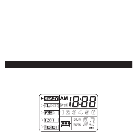
hooked up to a 6-Volt battery, the battery icon will appear
on the LCD.
Operati ng Instructions
Set Time
First, make sure that the timer unit is properly connected to
the bat ter y.
5
 Loading...