

Page 1
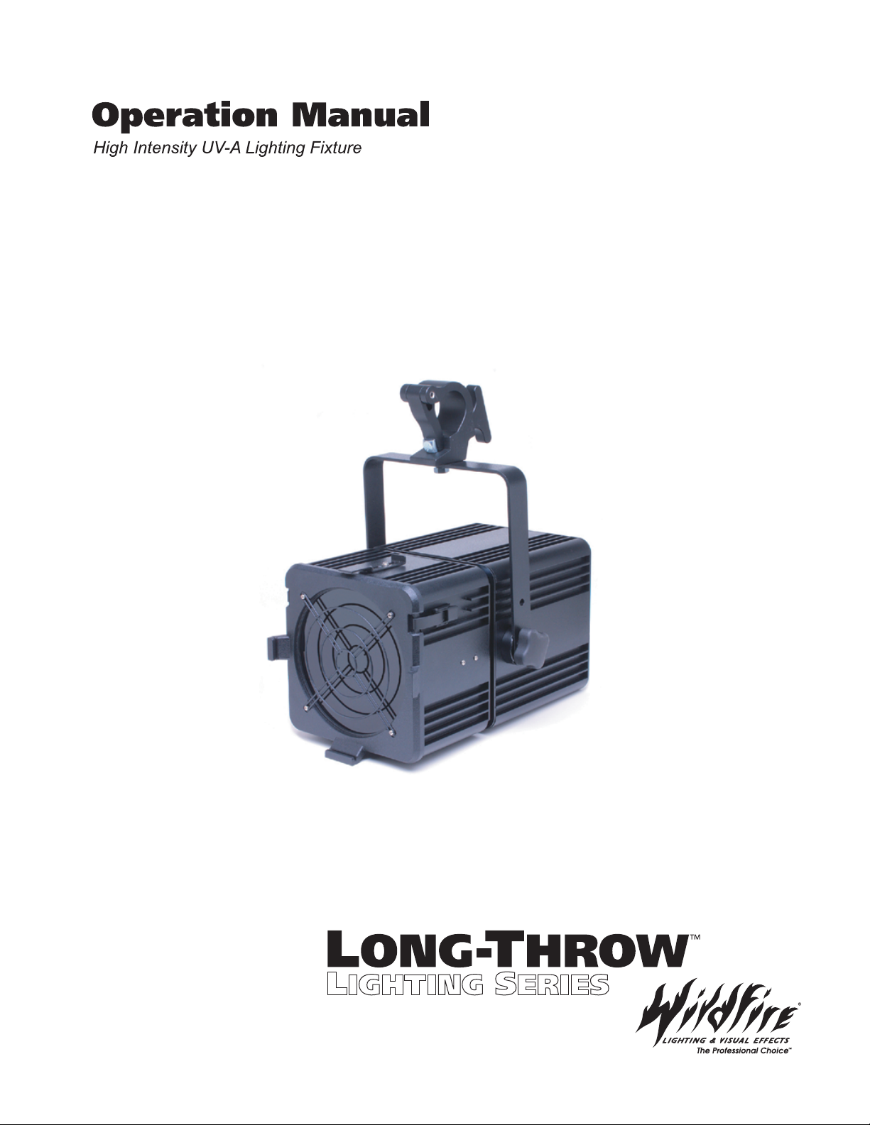
WF-402FF
WF-402FG
WF-402FH
WF-402FI
WF-402F1
WF-402F2
Page 2

Table of Contents
Introduction 3
Safety Statements 3
Specifications 4
Setup & Operation 5
Unpacking 5
Installation 5
Operation Electronic Ballast 5
Operation Magnetic Ballast 6
Maintenance & Troubleshooting 6
Lamp Replacement 6
Cleaning 6
Troubleshooting 6
Diagrams 7
Line View 7
Exploded View (Magnetic) 8
Part List (Magnetic) 9
Exploded View (Electronic) 10
Part List (Electronic) 11
Schematic (Magnetic) 12
Schematic (Electronic) 13
Schematic (Electronic DMX Option) 14
Spectral Transmission Graph & Photometrics Chart 15
2
Page 3

Introduction
Congratulations on your purchase of a Wildfire 402F Long-Throw UV -A Lighting Fixture. Designed to powerfully
illuminate fluorescent objects across a 90° field the Wildfire 400 watt flood has become the first choice for
lighting professionals around the world. Please take a moment to read this manual thoroughly before attempting
to operate this fixture. Improper set-up, use or servicing may cause damage to the fixture and/or lamp and void
the unit’s warranty.
Safety Statements
CAUTION – RISK OF EXPOSURE TO ULTRAVIOLET (UV) RADIATION DO NOT OPERATE WITHOUT
COMPLETE LAMP ENCLOSURE IN PLACE, OR IF FILTER GLASS LENS IS DAMAGED
DANGER – INTENSE HEAT AVOID CONTACT BY PERSONS AND MATERIAL.
CAUTION – RISK OF ELECTRICAL SHOCK AND FIRE DISCONNECT FIXTURE BEFORE RELA MPING. USE
WITH MAX 400W LAMP TYPE M59 (WILDFIRE IRONARC MODEL LMP-400D). DRY LOCATIONS ONLY.
NOT FOR RESIDENTIAL USE.
WARNING – THIS FIXTURE CONTAINS A HIGH INTENSITY UV METAL HALIDE LAMP, WHICH IS SAFELY
CONTAINED WITHIN AN INTERLOCKING HOUSING. WHEN TH IS FIXTURE IS USED IN ACCORDANCE
WITH THE MANUFACTURERS OPERATING INSTRUCTIONS, NO HAZARDS EXIST TO MOST PEOPLE
STANDING WITHIN THE BEAM OF THE FIXTURE. HOWEVER INDIVIDUALS SUFFERING FROM A RANGE
OF SUNLIGHT EXPOSURE DISORDERS, APHAKIC AND PSEUDOAPHIKIC, OR THOSE INDIVIDUALS
RECEIVING PHOTOSENSITIVE MEDICATION MAY RECEIVE DISCOMFORT IF EXPOSED TO
ULTRAVIOLET LIGHT.
3
Page 4

WF-402F Specifications
Ballast:
Magnetic
Electronic Power Factor >92%
Rating:
120VAC / 60Hz. / 5 Amps Max / 400W (Mag.)
100-120VAC / 50-60Hz. / 4 Amps Max / 400W (Elec.)
220VAC / 50-60Hz. / 2 Amps Max / 400W (Elec.)
Electronic Ballast Features:
Flicker & Noise Free
Automatic Lamp Failure Shutdown
Automatic High Temperature Shut Down
Automatic Hot Re-strike Prevention
Optional Magnetic Ballast Electrical Configurations:
100VAC / 50Hz.
100VAC / 60Hz.
120VAC / 50Hz.
Circuit Protection:
7 Amp Magnetic Over-current Breaker Switch
Lamp:
Wildfire IronArc® 400-Watt Metal Halide Model LMP-400D (1000 Hr. Rated)
Beam:
90° Flood
Reflector:
Specular Hammertone Aluminum
Lens:
8” UV -A Transmission Filter Glass
8” Clear Boro Float Front Glass (Optional)
Peak Spectral Transmission:
350-365nm
Optimum Operating Temperature:
+50°F to +120°F
Weight:
35.25Lbs. / 16.00Kg. (Mag.)
23.70Lbs. / 10.80Kg.(Elec.)
Dimensions:
10.18”/25.85cm High x 10.61”/26.94cm Wide x 16.38”/44.14cm Long
Accessory Bracket:
10” / 25.4cm Bracket Assembly
Standard Equipment:
Lamp (LMP-400D)
Pipe Mounting Clamp (ACC-0026)
Safety Cable (ACC-0027)
Specifications subject to change without notice
4
Page 5

Setup & Operation
Unpacking
Unpack the fixture and carefully inspect for any signs of physical damage. Report any damage to Wildfire or
your local distributor immediately. Included with each unit should be the following items:
1. Pipe mounting clamp, designed to attach the fixture to a 11/2” to 2” pipe truss
2. Safety Cable, Provided to secure the fixture when mounted on a pipe truss
3. Wildfire IronArc Lamp, Model LMP-400D
Before mounting the fixture you will need to install the lamp refer to Lamp Replacement on page 6 for correct
installation.
Installation
After installing the lamp place the fixture in desired location the fixture is equipped with a yoke assembly for
mounting. The yoke may be fitted with either a pipe clamp (included) for mounting on a pipe truss or a baby bail
block or junior pin for mounting on a light stand.
If the fixture is mounted on a pipe truss be sure to use the included safety cable looping it through the yoke
assembly and around the pipe truss this will prevent the fixture from falling and possibly causing injury in the
event that the pipe clamp was not securely tightened.
To adjust the angle of the fixture loosen the knobs on either side of the unit slightly, rotate to desired angle and
tighten. Care should be taken to support the front of the fixture while loosening the knobs to prevent the fixture
from rotating forward and possibly causing injury.
The fixture comes standard with a 10” Bracket assembly for attaching dowsers and scrollers such as Wybron’s
Eclipse or Coloram Series as well as barndoors and other accessories. When using accessories with this fixture
be sure to attach the safety cable provided by the accessory manufacturer to the fixtures yoke assembly.
Plug the fixture into the appropriate power source. If you are controlling the unit with a lighting control board you
will need to make sure it is plugged into a non-dim circuit if the fixture is plugged into a dimmable circuit it will
not operate.
Operation Electronic Ballast
To strike the fixture push the power/breaker switch to the on position Allow at least 2 minutes for the lamp to get
to full brightness. Once the fixture has been powered up and the lamp has ignited if you shut it off and try to turn
it back on the hot re-strike prevention circuitry in the ballast will prevent the lamp from striking until it is
completely cooled (approximately 5 minutes). If the power/breaker switch is left in the on position during this
cool down period the ballast will simply wait until the lamp is cool then strike automatically. The ballast is also
equipped with automatic lamp failure protection circuitry that shuts the fixture down if the lamp should fail for any
reason, preventing any damage to the components. In addition the ballast is equipped with high temperature
protection circuitry that shuts the fixture down if the ballast case temperature exceeds 85 C when the fixture
cools it will strike again automatically. If your fixture is equipped with DMX control you can switch the fixture on
or off via a DMX 512 signal by setting the DMX address switch on the back of the fixture to the desired address
(001 to 512). Once the fixture receives a DMX 512 data signal above 50% (127-255) the lamp will ignite. If the
data signal falls below 50% (0-126) the lamp will extinguish. Setting the DMX address on the fixture to 601
bypasses the DMX control and allows you to switch the fixture on or off manually. The DMX input connector pin
configuration is: Common Pin 1, Data Minus Pin 2, and Data Plus Pin 3. The lamp timer on the fixture counts the
number of hours the fixture is on. The timer will only operate when the fixtures power switch is in the on position.
This is used to determine when the lamp needs replacing. Wildfire recommends replacing the lamp every 1000
hours for maximum effect. The timer will automatically reset to zero upon reaching 9999:59:59. To reset it
manually depress the small button on the timer.
5
Page 6

Operation Magnetic Ballast
To strike the fixture turn the power/breaker switch to the on position Allow at least 2 minutes for the lamp to get
to full brightness. Once the fixture has been powered up and the lamp has ignited if you shut it off you will need
to wait approximately 5 minutes to allow the lamp to cool before the fixture can re-strike. If the power/breaker
switch is left in the on position during this cool down period the fixture will simply wait until it is cool then strike
automatically. This is not recommended however since it is hard on the ignitor.
The fixture is equipped with a lamp timer that counts the number of hours the fixture is on. The timer will only
operate when the fixtures power switch is turned on. This is used to determine when the lamp needs replacing.
Wildfire recommends replacing the lamp every 1000 hours for maximum effect. The timer will automatically
reset to zero upon reaching 9999:59:59. If you need to reset it manually depress the small button on the timer.
Maintenance and Troubleshooting
Lamp Replacement
Unplug the fixture. Remove any accessories from the front. Make sure the fixture is cool to the touch before
opening the front lens assembly cover. Unhook the clasps on either side of the fixture allowing the front lens
assembly cover to swing down. Grasp the lamp in the center remove it by pushing it gently to one side sliding
the other end forward. Reverse this procedure to install the new lamp. After installing gently rock the new lamp
back and forth to insure the depressions on the ends of the lamp are firmly seated on the posts of the sockets. If
the lamp is not firmly seated arcing could occur melting both the socket and lamp. Care should be taken not to
touch the new lamp directly use a cloth or glove when handling if you have touched the lamp it must be cleaned
with alcohol to remove any oils and fingerprints prior to striking. For maximum UV -A output always use Wildfire
IronArc™ lamps, and change the lamp in your fixture every 1000 hours.
Cleaning
For best performance, the reflector, lamp and filter lens should be kept free of dirt and dust. At no time should
any cleaning chemicals or abrasives be used to clean any part of the fixture. Do not spray or apply any liquid
directly to any part of the fixture. Always unplug the unit before cleaning. For normal cleaning, a dry soft cloth
should be used to wipe any surface free from dust and light dirt. Cleaning the reflector will require that the lamp
be removed. Remove the lamp by following the instructions listed under lamp replacement above. Once the
lamp has been removed, gently wipe off the reflector using a soft dry cloth. In the event the reflector is heavily
soiled, lightly dampen the cloth with a mild window cleaning agent and wipe clean. The filter lens can be cleaned
in the same manner. The lamp should be cleaned with alcohol only.
Troubleshooting
Other than the lamp, there are no user serviceable parts in the fixture.
The fixture will not light – Check to make sure there is power to the unit. Make sure the power/breaker switch
on the back of the fixture has not been tripped. Unplug the unit. Open the front lens cover and check to see if
the unit has a lamp installed and that it is seated properly in the sockets (see lamp replacement above). Check
to see if the safety cutoff switch is making contact by closing the lens cover and listening for a clicking sound. If
the unit still is not lighting try replacing the lamp. If you have checked all of the above and the fixture still won’t
light contact Wildfire or your local distributor.
The fixture turns on and off – Check to see that the lamp is seated properly in the sockets (see lamp
replacement above). If the lamp is seated properly and the fixture is still turning on and off the lamp may be bad
try replacing the lamp. If the fixture is still not working properly contact Wildfire or your local distributor.
The effect is not working anymore – Try changing the lamp. The lamp in your Wildfire fixture is rated at 1000
hours. This does not necessarily mean that the lamp will “burn out” or not light after 1000 hours it may continue
to burn for much longer period of time however the amount of UV it produces will be reduced considerably
causing the effect to appear as though it isn’t working. Wildfire recommends for maximum effect to change the
lamp every 1000 hours.
6
Page 7
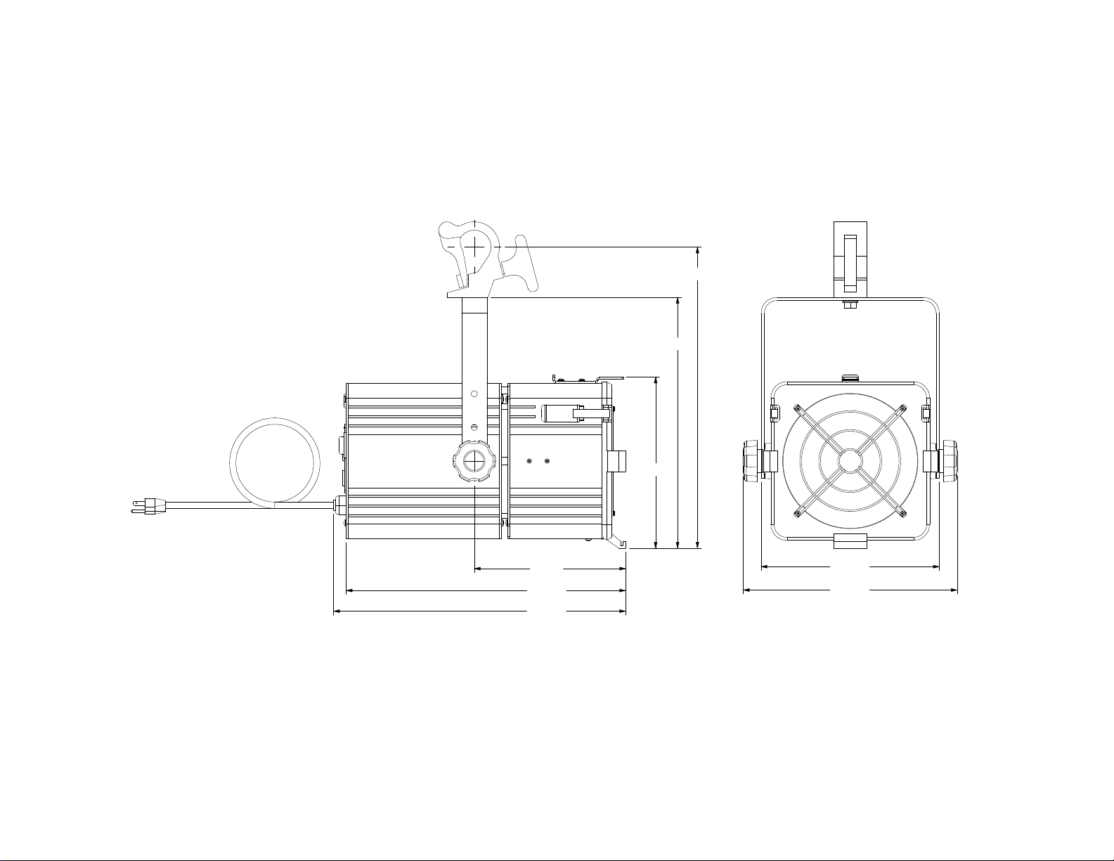
Line View
Diagrams
17.92
14.92
10.18
9.01
16.63
17.38
10.61
12.74
7
Page 8
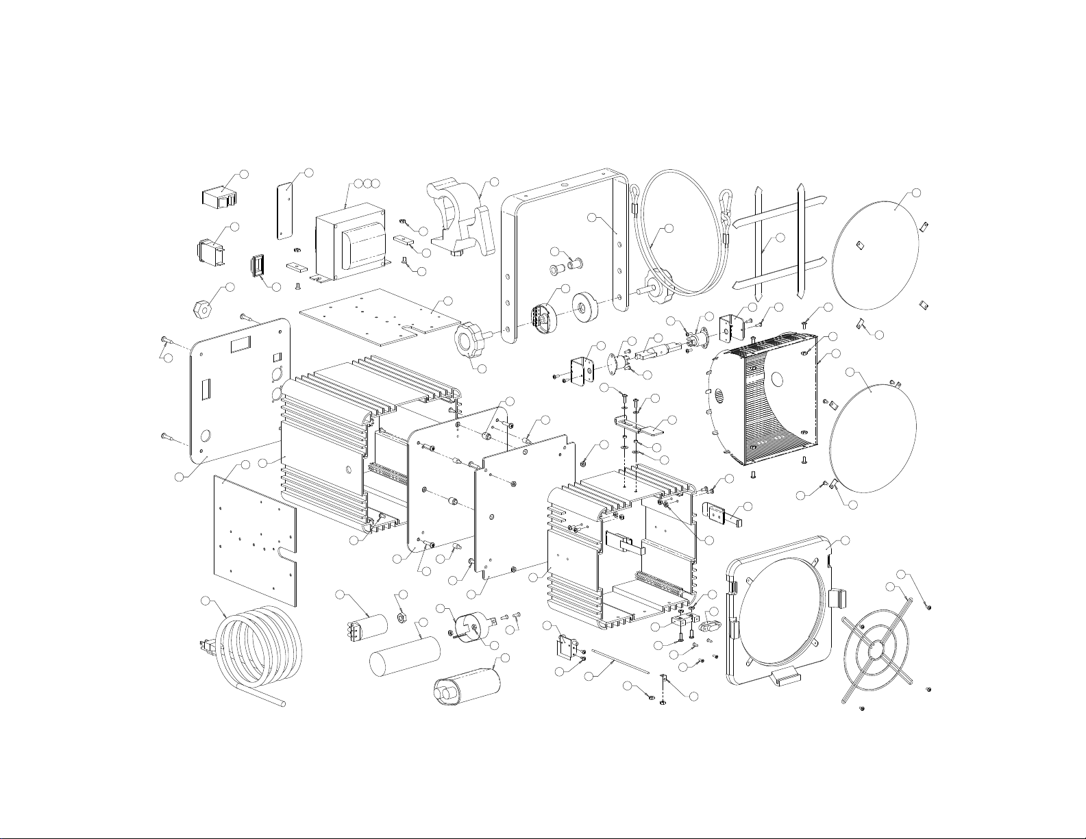
Exploded View (Magnetic Ballast)
5
2
7
49
31
19
12
9
16
1
55 56 57
45
51
50
12
42
22
3
39
49
49
4
27
58
25
20
36
26
17
28
40
11
39
43
32
21
6
44
43
59
54
18
43
30
8
41
35
8
41
46
15
48
38
42
43
53
24
10
40
37
37
47
17 41
29
23
42
43
60
33
54
52
13
34
52
54
14
8
Page 9

Part List (Magnetic Ballast)
# QTY. PART # PART NAME
1 1 ELE-0005 APM Hexseal, Breaker Switch
2 1 ELE-0009 Breaker, Switch, Carling, 5 amp
3 1 ELE-0012 Ignitor, 12 Amp
4 1 Included w/ Ignitor Nut, 3/8-16
5 1 ELE-0015 Timer, Lamp
6 1 ELE-0016 Switch, Honeywell, 2AC59
7 1 ELE-0021 Strain Relief, Power Cord
8 2 ELE-0024 Socket, Lamp, B&W 976, (252)(402)(402S/F)
9 1 ELE-0038 Power Cord, 120V
10 1 FAB-0002-A Bracket, Hinge, Soss
11 3 FAB-0006-A Bushing, Wire & Switch Routing
12 2 FAB-0007-D Component Plate, 9", 402
13 1 FAB-0011-E Lens Door, 8" Round
14 1 FAB-0013-A Safety Screen, 401
15 1 FAB-0016-A Slide Lock, Accessory
16 1 FAB-0020-C Cover Plate, DMX
17 2 FAB-0022-A Bracket, Socket, B&W 946, 401, (F)
18 1 FAB-0026-A Rod, Switch, 402F
19 1 FAB-0073-C Back Plate, 400
20 1 FAB-0074-E Yoke, 401 / 600
21 1 FAB-0121-B Divider Plate, Lamp, 400
22 1 FAB-0122-B Divider Plate, Ballast, 400
23 4 GKT-0002 Gasket, Lens Door, 401/600
24 1 HAR-0017 Hinge, Soss, #101, Chrome
25 1 HAR-0019 Pipe Clamp, Mega Claw
26 2 HAR-0020-A Spacer, Casting, Yoke
27 1 HAR-0023 Bracket, Capacitor
28 2 HAR-0050 Knob, Yoke Adjustment
29 2 HAR-0076 Latch, Draw
30 1 HAR-2000 Cable, Safety, 1/8"
# QTY. PART # PART NAME
31 1 HSG-400B-A Housing, Ballast, 400
32 1 HSG-400LF-D Housing, Lamp, 400, (F)
33 1 LEN-0005 Lens, 8" Round, Mug 2
34 1 LEN-0015 Lens, 8" Round, Boro Float
35 1 LMP-400D Lamp, Wildfire, Iron Arc, UV, 400W
36 2 MFG-0001 Nut, Blind Rivet
37 4 MFG-0006 MS, FH, PHL, 5-40, .375", 18-8 SS
38 2 MFG-0015 Spring, Belleville Disc
39 4 MFG-0022 Standoff, 5/16 OD, 8-32, M-F
40 4 MFG-0031 MS, PH, PHL, 8-32, .500", 18-8 SS
41 8 MFG-0034 MS, PH, PHL, 6-32, .375", 18-8 SS
42 12 MFG-0035 MS, PH, PHL, 8-32, .375", 18-8 SS
43 16 MFG-0041 Nut, 8-32, 18-8 SS, w/ Tooth Washer
44 2 MFG-0043 MS, FH, PHL, 8-32, .500", 18-8 SS
45 2 MFG-0044 Nut, 10-32, 18-8 SS, Nylok
46 2 MFG-0051 Washer, 3/8 OD, 11/64 ID, .032 Thk, 18-8 SS
47 1 MFG-0053 Bracket, Keystone
48 2 MFG-0054 Standoff, 1/4 OD, 1/8 Tall, #8, Alum
49 12 MFG-0055 SS, PH, PHL, #10, 1", 18-8 SS
50 2 MFG-0056 MS, FH, PHL, 10-32, .375", 18-8 SS
51 2 MFG-0063 Washer Rectangular
52 8 MFG-0067 Clip, Lens Retaining
53 2 MFG-0076 Nut, 8-32, Hex, Small Pattern
54 10 MFG-0078 MS, PH, PHL, 6-32, .250", 18-8 SS
55 1 PS-MH-400F Ballast, 400W, 100-200V, 50HZ
56 1 PS-MH-400G Ballast, 400W, 100-200V, 60HZ
57 1 PS-MH-400IK Ballast, 400W, 120-277V, 60HZ
58 1 Included w/Ballast Capacitor, Dry
59 1 Included w/Ballast Capacitor, Oil
60 1 RFL-004 Reflector Assy. WF-402F
9
Page 10
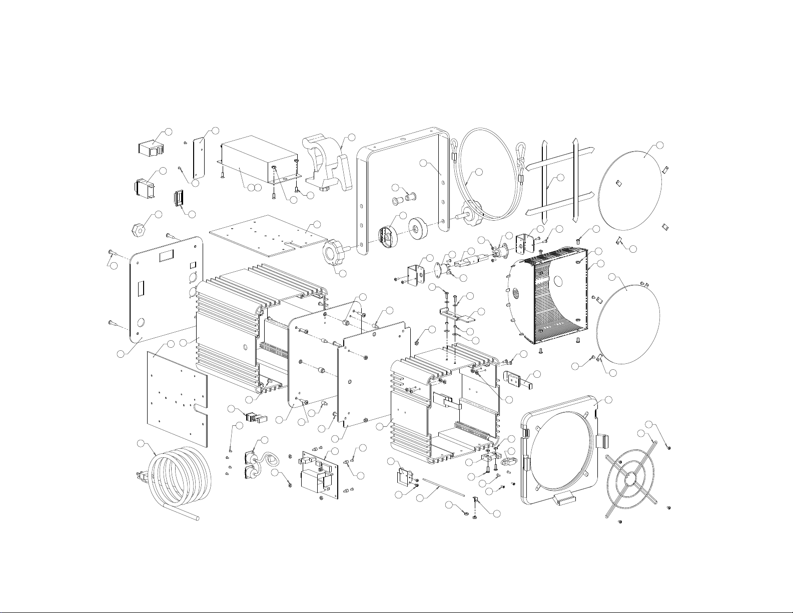
Exploded View (Electronic Ballast)
3
2
5
49
29
11
18
8
15
38
1
54 55
41
7
38
21
7
42
44
43
11
37
49
49
24
19
34
25
16
26
39
10
37
43
30
20
50
7
4
46
53
17
43
28
40
33
6
40
45
14
48
36
9
39
6
41
43
52
23
35
35
47
16 40
27
22
41
43
56
31
53
51
12
32
51
53
13
10
Page 11

Part List
# QTY. PART # PART NAME
1 1 ELE-0005 APM Hexseal, Breaker Switch
2 1 ELE-0009 Breaker, Switch, Carling, 5 amp
3 1 ELE-0015 Timer, Lamp
4 1 ELE-0016 Switch, Honeywell, 2AC59
5 1 ELE-0021 Strain Relief, Power Cord
6 2 ELE-0024 Socket, Lamp, B&W 976, (252)(402)(402S/F)
7 1 ELE-0029 DMX Board, Socket & Switch
8 1 ELE-0038 Power Cord, 120V
9 1 FAB-0002-A Bracket, Hinge, Soss
10 3 FAB-0006-A Bushing, Wire & Switch Routing
11 2 FAB-0007-D Component Plate, 9", 402
12 1 FAB-0011-E Lens Door, 8" Round
13 1 FAB-0013-A Safety Screen, 402
14 1 FAB-0016-A Slide Lock, Accessory
15 1 FAB-0020-C Cover Plate, DMX
16 2 FAB-0022-A Bracket, Socket, B&W 946, 402, (F)
17 1 FAB-0026-A Rod, Switch, 402F
18 1 FAB-0073-C Back Plate, 400
19 1 FAB-0074-E Yoke, 402
20 1 FAB-0121-B Divider Plate, Lamp, 400
21 1 FAB-0122-B Divider Plate, Ballast, 400
22 4 GKT-0002 Gasket, Lens Door, 402
23 1 HAR-0017 Hinge, Soss, #101, Chrome
24 1 HAR-0019 Pipe Clamp, Mega Claw
25 2 HAR-0020-A Spacer, Casting, Yoke
26 2 HAR-0050 Knob, Yoke Adjustment
27 2 HAR-0076 Latch, Draw
28 1 HAR-2000 Cable, Safety, 1/8"
# QTY. PART # PART NAME
29 1 HSG-400B-A Housing, Ballast, 400
30 1 HSG-400LF-D Housing, Lamp, 400, (F)
31 1 LEN-0005 Lens, 8" Round, Mug 2
32 1 LEN-0015 Lens, 8" Round, Boro Float
33 1 LMP-400D Lamp, Wildfire, Iron Arc, UV, 400W
34 2 MFG-0001 Nut, Blind Rivet
35 4 MFG-0006 MS, FH, PHL, 5-40, .375", 18-8 SS
36 2 MFG-0015 Spring, Belleville Disc
37 4 MFG-0022 Standoff, 5/16 OD, 8-32, M-F
38 4 MFG-0028 MS, FH, PHL, M3, 8mm, 18-8 SS
39 4 MFG-0031 MS, PH, PHL, 8-32, .500", 18-8 SS
40 8 MFG-0034 MS, PH, PHL, 6-32, .375", 18-8 SS
41 12 MFG-0035 MS, PH, PHL, 8-32, .375", 18-8 SS
42 4 MFG-0040 Nut, 6-32, 18-8 SS, w/ Tooth Washer
43 18 MFG-0041 Nut, 8-32, 18-8 SS, w/ Tooth Washer
44 4 MFG-0043 MS, FH, PHL, 8-32, .500", 18-8 SS
45 2 MFG-0051 Washer, 3/8 OD, 11/64 ID, .032 Thk, 18-8 SS
46 4 MFG-0052 Standoff, 1/4 OD, 1/4 Tall, 6-32, M-F
47 1 MFG-0053 Bracket, Keystone
48 2 MFG-0054 Standoff, 1/4 OD, 1/8 Tall, #8, Alum
49 12 MFG-0055 SS, PH, PHL, #10, 1", 18-8 SS
50 4 MFG-0060 MS, FH, PHL, 6-32, .250", 18-8 SS
51 8 MFG-0067 Clip, Lens Retaining
52 2 MFG-0076 Nut, 8-32, Hex, Small Pattern
53 10 MFG-0078 MS, PH, PHL, 6-32, .250", 18-8 SS
54 1 PS-MH-400L1 Ballast, Electronic, 120V, 50-60HZ, 400W
55 1 PS-MH-400L2 Ballast, Electronic, 220V, 50-60HZ, 400W
56 1 RFL-004 Reflector Assy. WF-402F
11
Page 12
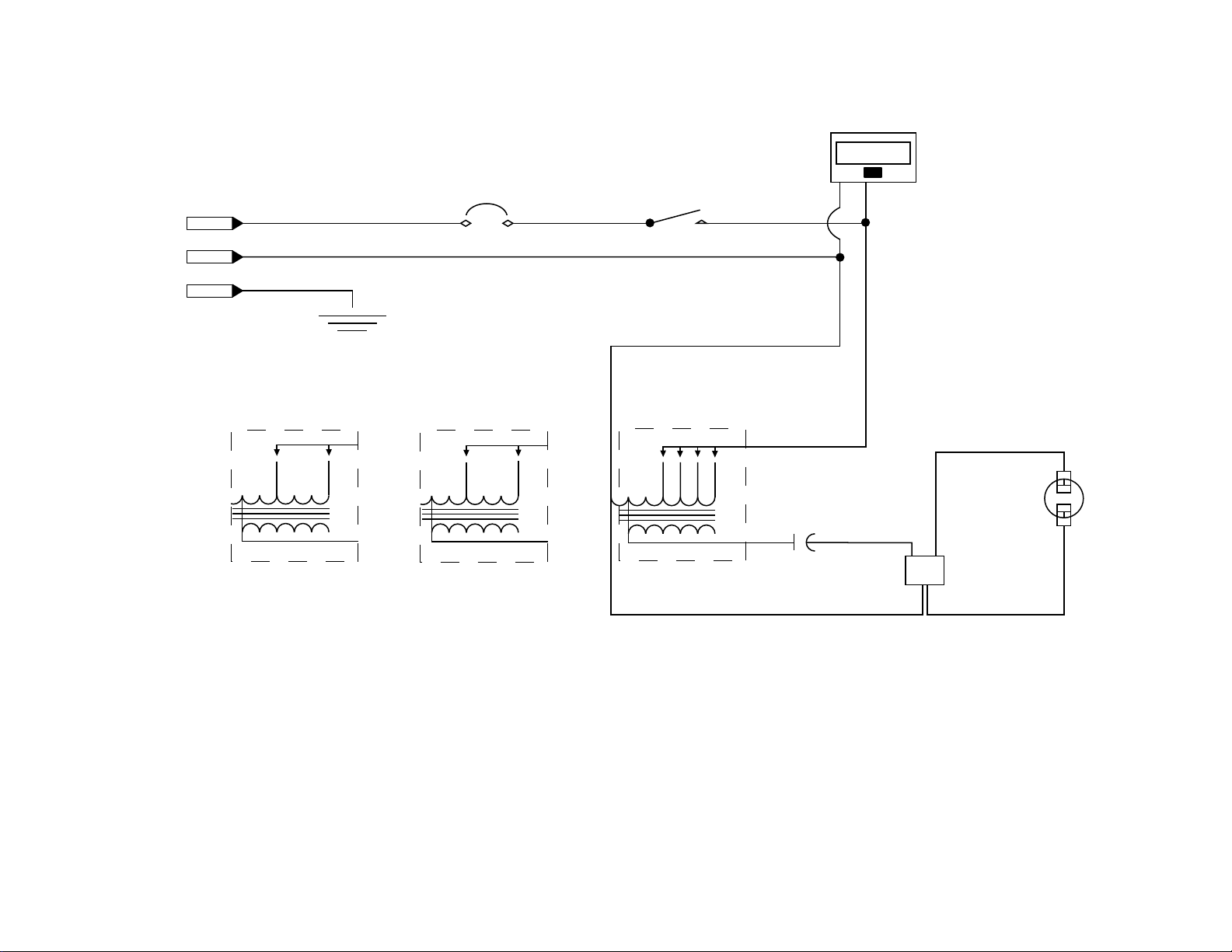
Schematic (Magnetic Ballast)
LAMP TIMER
100/277V
COM
GRND
PS-MH400F Ballast
100V
200V
POWER SWITCH
7 AMP CIRCUIT BREAKER
PS-MH400G Ballast
100 or 200VAC / 60Hz.100 or 200VAC / 50Hz.
&
100V
200V
SAFETY SWITCH
PS-MH400IK Ballast
120V
COM COM
120-277VAC / 60Hz.
9999:59:59
208V
240V
277V
CAPACITOR
B LP
N
IGNITOR
LAMP
400W
12
Page 13
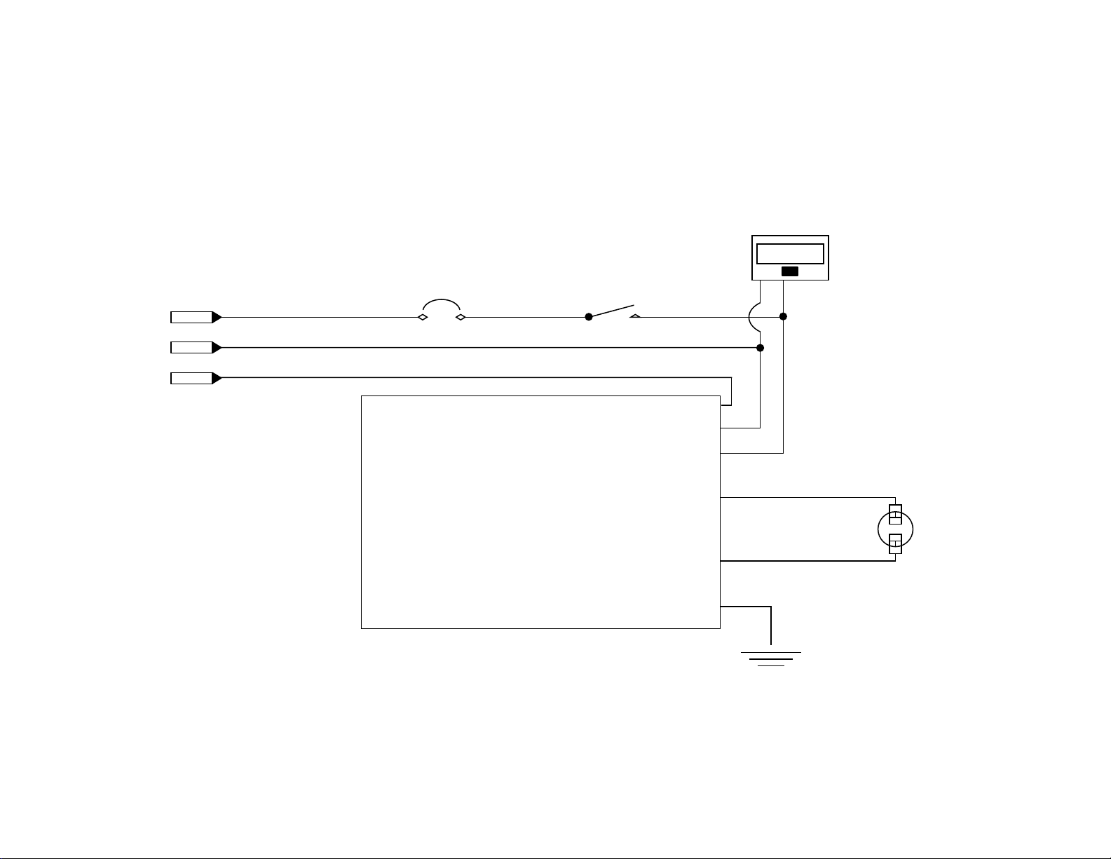
Schematic (Electronic)
LAMP TIMER
220V
COM
GRND
POWER SWITCH
7 AMP CIRCUIT BREAKER
&
SAFETY SWITCH
400W ELECTRONIC BALLAST
9999:59:59
G
N
L
LAMP
LAMPGROUND
400W
13
Page 14
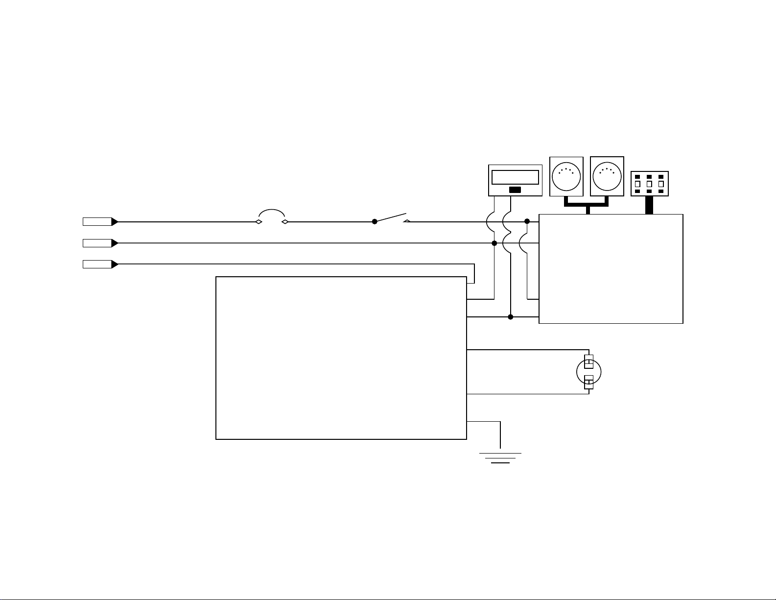
Schematic (Electronic DMX Option)
220V
COM
GRND
POWER SWITCH
&
7 AMP CIRCUIT BREAKER
400W ELECTRONIC BALLAST
SAFETY SWITCH
LAMP TIMER
9999:59:59
DMX IN DMX OUT
L
N
DMX ADDRESS
6
1
0
DMX CONTROL BOARD
G
N
L
LAMP
COM
NO
LAMP
400W
GROUND
14
Page 15
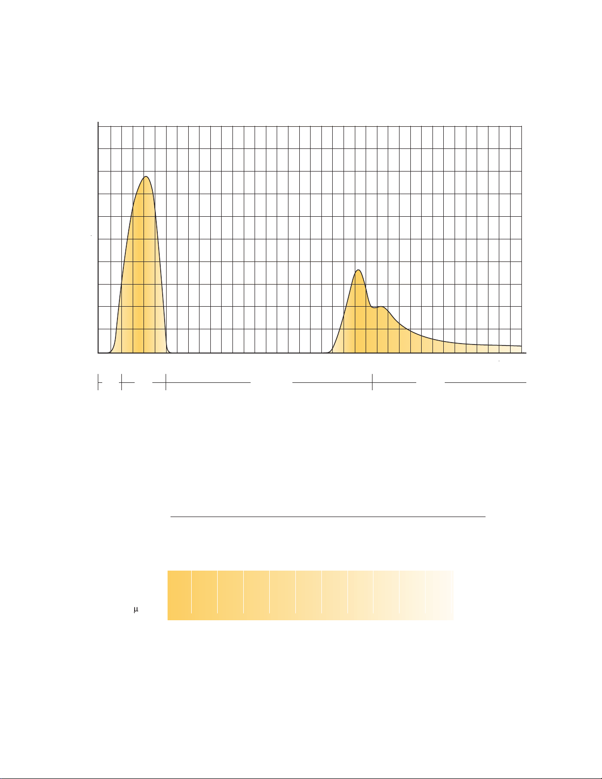
Spectral Transmission Graph
100
90
80
70
60
50
40
TRANSMISSION /%
30
20
10
0
280
300
320
340
UV-B UV-A
400
360
380
420
440
480
460
500
520
540
560
580
600
620
640
660
680
700
720
740
760
VISIBLE LIGHT
820
780
800
840
860
INFRARED
900
880
940
920
960
980
1100
1000
1200
Photometrics Chart
Beam Diameter Feet
Beam Diameter Meters
Peak UV-A Intensity W/cm
90° Flood
Distance in Feet/Meters
5
6.10
/
30
60
18.29
14.1
9.14
/
3.0
/
10
20
20
40
12.19
6.10
2
116
31
40
80
24.38
7.9
WAVELENGTH /NM
19
12.
15.24
/
/
50
100
30.48
36.57
5.1
120
3.6
60
18.29
/
70
140
42.67
2.6
21
/
.33
160
48.77
1.9
80
24.38
/
90
180
54.86
1.6
27.4
/
3
10
200
60.96
1.3
0
30.48
/
11
220
67.05
1
0
33.53
/
15
Page 16

5200 West 83rd Street, Los Angeles, CA 90045
310-645-7787 800-937-8065 Fax: 310-645-9009
www.wildfirefx.com [email protected]
Wildfire and its symbol are registered trademarks of Wildfire, Inc. Los Angeles, CA
The Professional Choice Long Throw and IronArc are trademarks of Wildfire, Inc. Los Angeles, CA
c
2003 Wildfire, Inc.
 Loading...