

Wildfire VS-60, VS-120 Operation Manual
Operation Manual
365nm Ultraviolet LED Lighting Fixtures
VS-60
VS-120
English

Table of Contents
Introduction 3
Safety Information 3
Specifications 4
Setup & Operation 5
Unpacking 5
Optional Accessories 5
Installation 5
Local Contr ol Source Operation 5
Effects (Local) 5
DMX512 Contr ol Sourc e Operation 6
Effects (DMX512) 6
RDM Functions 6
Graphical Menu Tree 7
DMX Chart 10
Maintenance 11
Optic Change/Replacement 11
Software Updates 11
Cleaning 11
Troubleshooting 11
Diagrams 12
Isometric & Line Views VS-60 12
Isometric & Line Views VS-120 13
Exploded View VS-60 14
Part List VS-60 15
Exploded View VS-120 16
Part List VS-120 17
Schematic VS-60 18
Schematic VS-120 19
Spectral Output & Photometrics VS-60 20
Spectral Output & Photometrics VS-120 21
Limited Warranty 22
2

Introduction
Congratulations on your purchase of a Wildfire VioStorm Series UV-A Lighting Fixture. VioStorm fixtures
combine true 365nm Long Throw performance, with the control and efficiency of LED's. Featuring Wildfire’s
intuitive new Trias DMX/RDM Control System and versatile interchang eab le opt ics , VioStorm UV lighting is just
the right combination of power performance and control for a perfect black light storm. Please take a moment to
read this manual thoroughly before attempting to operate the fixture. Improper set-up, use or servicing may
cause damage to the fixture and void the unit’s warranty.
Safety Information
RISK GROUP 3 - WARNING - THIS FIXTURE EMITS ULTRAVIOLET RADIATION (UV) AT A PRIMARY
WAVELENGTH OF 365NM, AVOID EYE AND SKIN EXPOSURE AT DISTANCES SHORTER THAN 3.3’ (1m).
DO NOT LOOK INTO THE BEAM DIRECTLY AT DISTANCES SHORTER THAN 11’ (3.3m) OR VIEW THE
BEAM DIRECTLY WITH OPTICAL INSTRUMENTS THAT MAY CONCENTRATE THE LIGHT/RADIATION
OUTPUT.
CAUTION – WHEN USED IN ACCORDANCE WITH THE MANUFACTURERS OPERATING INSTRUCTIONS,
NO HAZARDS EXIST TO MOST PEOPLE AT DISTANCES GREATER THAN 11’ (3.3m) FROM THE FIXTURE.
HOWEVER, INDIVIDUALS SUFFERING FROM A RANGE OF SUNLIGHT EXPOSURE DISORDERS,
APHAKIC AND PSEUDOAPHIKIC, OR THOSE INDIVIDUALS RECEIVING PHOTOSENSITIVE MEDICATION
MAY RECEIVE DISCOMFORT IF EXPOSED TO ULTRAVIOLET LIGHT.
CAUTION – NOT FOR RESIDENTIAL USE. DRY LOCATIONS ONLY.
3

Housing:
5052 aluminum with stainless steel hardware
Finish:
Flat black powder coat
Mounting:
Fully adjustable yoke with three height positions and integrated removable floor stand
UV Light Source:
VS-60: Six 10W 365nm UV LED emitters
VS-120: Twelve 10W 365nm UV LED emitters
Radiant Power:
VS-60: 12,240 mW
VS-120: 24,480 mW
LED Life:
20,000Hr. at 25° C
Optics:
Molded Silicone 10°, 24° or 40°
Operating Temperature:
-10° to 115° F / -20° to 45° C
Humidity:
0-95% non-condensing
Power Connections:
Neutrik PowerCON 1 Input and Output
Power Linking:
VS-60: Eight units at 120VAC
VS-120: Four units at 120VAC
Power Cord:
9’ 14/3 SOW with PowerCON 1 and male Edison
DMX Connections:
Neutrik Gold, 5-pin XLR Male, 5-pin XLR Female
DMX Channels:
Three (2 Dimming, 1 Effects)
Control Modes:
Two (DMX 512 and Local)
Operation Modes:
Three (1 Channel, 2 Channel, 3 Channel)
USB Connection:
Amphenol Rugged Mini-B USB Female
Input Voltage:
100-240 VAC
Input Current
VS-60: 0.88 Amps Max
VS-120: 1.73 Amps Max
Frequency:
50-60Hz.
Power Factor:
0.97
Power Consumption:
VS-60: 86 Watts
VS-120: 170 Watts
Circuit Protection:
7 Amp hydraulic magnetic breaker switch
Accessory Frame:
7.5” / 19.05cm
10” / 25.4cm
Weight:
VS-60: 10.35 lbs. / 4.69 kg.
VS-120: 13.35 lbs. / 6.05 kg
Protection Rating:
IP-20
Safety Listing:
ETL #5004307
Specifications
4

Setup & Operation
Unpacking
Unpack the fixture and carefully inspect for any signs of physical damage. Report any damage to Wildfire or
your local distributor immediately. Included with each unit should be the following items:
1. Twenty clamp, designed to attach the fixture to a 11/2” to 2” pipe truss
2. Safety Cable, provided to secure the fixture when mounted on a pipe truss
3. 9’ Power Cable
5. 3’ USB Cable
6. PowerCON 1 Power-Out Cable Connector
7. Operation Manual and Warranty Registration Card
Optional Accessories
Contact Wildfire or your local distributor for pricing on the following opt ional ac c ess or ies:
1. 7.5” and 10” Barn Doors
2. 10° Spot Optic Set
3. 24° Spot Optic Set
4. 40° Spot Optic Set
Installation
The fixture is equipped with a yoke assembly for mounting. The yoke may be fitted with either a pipe clamp
(included) for mounting on a pipe truss or a baby bail block or junior pin for mounting on a light stand.
If the fixture is mounted on a pipe truss, be sure to use the included safety cable, looping it through the yoke
assembly and around the pipe truss. This will prevent the fixture from falling and possibly causing injury in the
event that the pipe clamp was not securely tightened.
To adjust the angle of the fixture, loosen the knobs on either side of the unit slightly, rotate to desired angle and
tighten. Care should be taken to support the front of the fixture while loosening the knobs to prevent the fixture
from rotating forward possibly causing inj ur y.
The fixture comes standard with a 7.5” (VS-60) or 10” (VS-120) bracket assembly for attaching barn doors and
other accessories. When using accessories, be sure to attach the safety cable provided by the accessory
manufacturer to the fixture yoke assembly.
Plug the fixture into the appropriate power source. If you are controlling the fixture with a lighting control board,
you will need to make sure it is plugged into a non-dim circuit. If the fixture is plugged into a dimmable circuit, it
will not operate.
Local Control Source
To operate the fixture in local control, turn the fixture ON by pushing the power/breaker switch to the ON
position. Set the Control Source menu selection to “Local.” Set the Dimmer menu selection to the desired output
level (0 – 100%). Set the Effect menu selection to the effect you want.
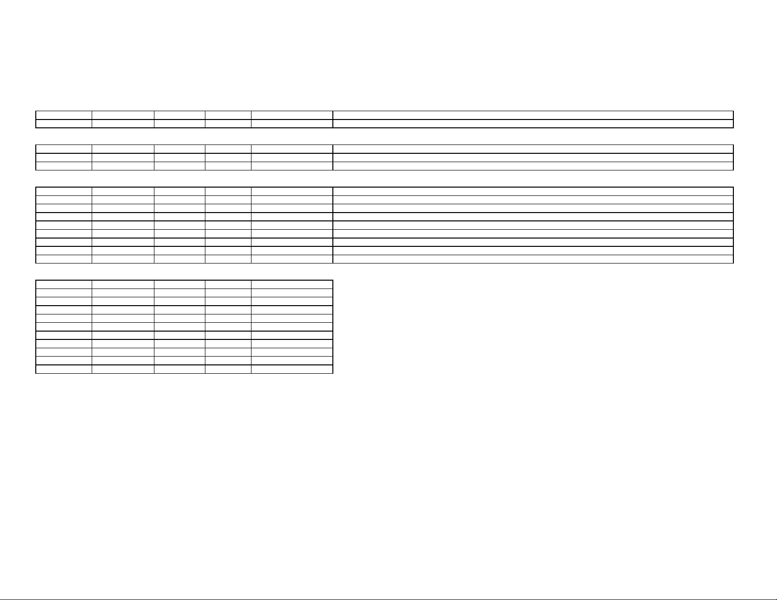
Effects (Local)
To utilize one of the fixtures preprogramed effects in local control, set the Eff ec ts menu selec tion to the desired
effect. There are six different adjustable effects to choose from
Setting Function Description
OFF No Effects All LED's static at the brightness set on the Dimmer sett ing
Strobe 1-60 Strobe Adjustable strobe of all LED's at the brightne ss set on the Dimmer setting
Flash 1-60 Flash Adjustable flash of all LED's at the bright ness set on the Dimmer setting
Pulse 1-60 Pulse Adjustable pulse of all LED's at the brightness set on the Dimmer setting
Random 1-60 Random Adjustable random strobe of all LED's at the brightness set on the Dimmer setting
Slow Fade 1-10 Fade Adjustable fade sequence of all LED's at the brightness set on the Dimmer setting
5

DMX512 Control Source
To operate the fixture with a DMX 512 control source, connect the fixture to a DMX control device such as a
lighting control board or lighting control software. Turn the fixture ON by pushing the power/breaker switch to the
ON position. Set the Control Source menu selection to “DMX512”. If the fixture is receiving valid DMX data, you
will see three dots flashing in lower the right-hand corner of the display. Next from the DMX Mode menu
selection set the total number of channels you want to use. There are three different DMX Modes to choose
from:
1 Channel Mode
Dimming Coarse
2 Channel Mode
Dimming Coarse
Dimming Fine
3 Channel Mode
Effects
Dimming Coarse
Dimming Fine
Next from the DMX Address menu selection set the starting DMX address you want to use. The total number of
addresses available to choose from depends on the DMX Mode you have selected. 1 Channel (001-512), 2
Channel (001-511), 3 Channel (001-510). Subsequent addresses will be in numer ical order.
Effects (DMX512)
To utilize one of the fixtures preprogramed effects in DMX512 control, set the effects channel DMX address to
the desired effect setting. There are six different adjustable effects to choose from:
Data Value Function Description
0-9 No Effects All LED's static at the brightness set on the dimmer channels
10-59 Strobe Adjustable Strobe of all LED's at the output set on the dimmer channels
60-109 Flash Adjustable Flash of all LED's at the output set on the dimmer channels
110-159 Pulse Adjustable Pulse of all LED's at the output set on the dimmer channels
160-209 Random Adjustable Random Strobe of all LED's at the output set on the dimmer channels
210-255 Slow Fade Adjustable fade sequence of all LED's at the brightness set on the dimmer channels
RDM
Remote Device Management is a protocol enhancement to DMX512 that allows bidirectional communication
between a system controller and attached RDM-compliant devices over a standard DMX line. This allows for
remote configuration, status monitoring, and management of the connected RDM devices. VioStorm fixtures are
compliant with RDM protocol and support monitoring and setting of the following parameters:
Fixture Model Displays the fixture model followed by the current optic setting
Fixture Label Display and remotely set fixture label
Manufacturer Displays the fixture manufacturers name
Software Version Displays the fixtures current software version
DMX Address Display and remotely set DMX starting address.
Lamp Hours Displays the total hours that the fixture has been on
Lamp State Displays the current LED state, OFF or ON
Temperature Displays the current LED module temperature with over temperature warning at 55C
Fan RPM Displays the current RPM for fans A & B with fan failure warnings at 0 RPM
Device ID Display fixtures unique device ID
In both DMX and Local control if no buttons are pressed for 60 seconds the display will go dark. To reactivate
the display, press any button.
The LED Hours function records the total number of hours the fixture has been on. To reset this, select the LED
Hours menu selection and then pr es s and ho ld the UP or DOWN button for 6 seconds.
VioStorm fixtures are equipped with automatic high temperature protection circuitry that shuts the LED’s off if
the temperature exceeds 70° C. Once it cools to 65° C the LED’s will turn back on.
6
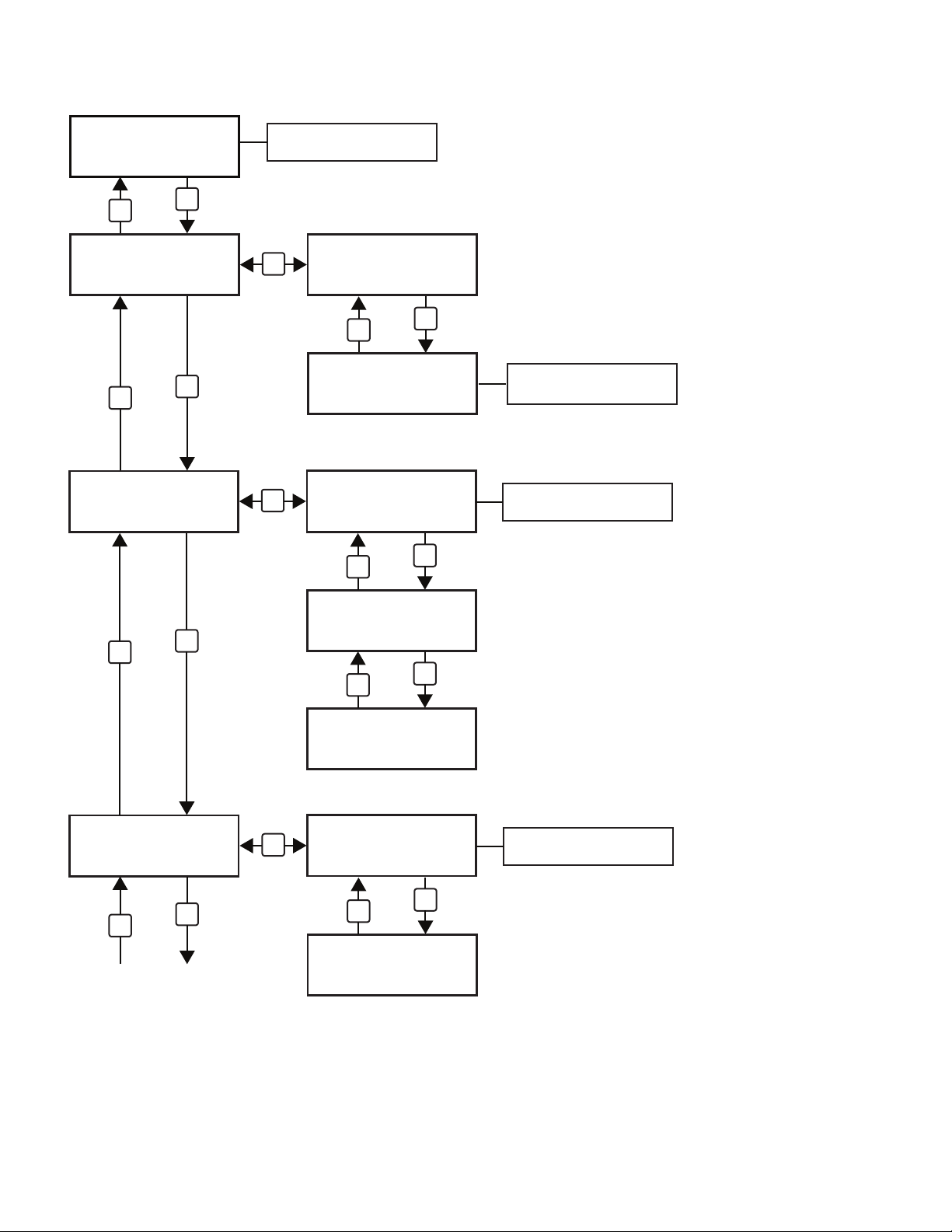
Graphical Menu Tree
Home Menu
VioStorm VS-60
Revision 1.2
DOWN
Control Source
>
UP
Local
DOWN
>
DMX Mode
UP
1 Channel
RDM: Display Fixure Model
and Software Revision
SELECT
Control Source
Local>
DOWN
Control Source
DMX512 ...>
SELECT
DMX Mode
1 Channel ...>
DOWN
UP
When DMX Signal is present
3 dots flash on display
RDM: Display DMX Mode
UP
DOWN
DMX Address
>
509
DOWN
Next Page
DMX Mode
UP
2 Channel ...>
DOWN
UP
DMX Mode
3 Channel ...>
SELECT
DMX Address
509 ...>
UP
DOWN
UP
RDM: Display and set DMX
address
DMX Address
510 ...>
7
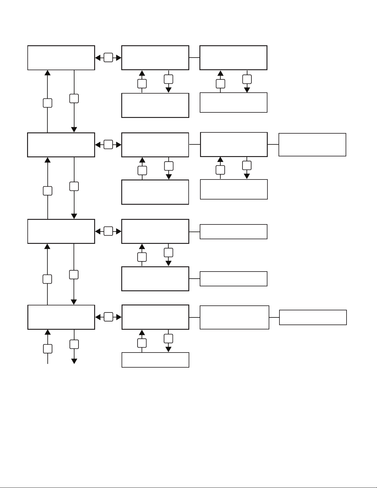
Graphical Menu Tree
Local Control Source DMX512 Control Source
Dimmer
>
7%
DOWN
>
Effect
Off
DOWN
>
LED Hours
25
SELECT
Dimmer
7%>
DOWN
UP
Dimmer
UP
8%>
SELECT
Effect
Off>
DOWN
UP
Effect
UP
Strobe 1>
SELECT
LED Hours
Dimmer
7%>
DOWN
Pressing UP or DOWN has no
function when Control Source
is set to DMX
UP
Effect
Off>
DOWN
Pressing UP or DOWN has no
function when Control Source
is set to DMX512
RDM: Displays Lamp Hours
UP
Effects Selections are:
Off, Strobe 1-60, Flash 1-60,
Pulse 1-60, Random 1-60 and
Slow Fade 1-10
25>
DOWN
>
Temperature
25C
DOWN
Next Page
DOWN
UP
LED Hours
0>
SELECT
Temperature
25C>
UP
DOWN
Pressing UP or DOWN has no
function.
UP
Pressing UP or DOWN for 6
seconds resets the LED hours
When the temperature exceeds
70C the LED’s will will shut off.
Once it cools to 65C the LED’s
will turn back on
UP
RDM: Display temperature
and overtemp warning at 55C
8
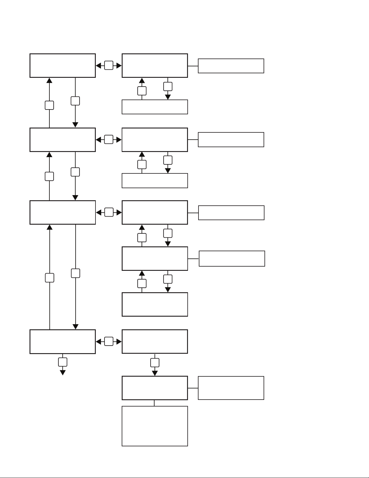
Graphical Menu Tree
Fan RPM
>
A-4000 B-4000
DOWN
Device ID
>
0X57466E228870
DOWN
>
Optic Type
0°
Flood
4
SELECT
Fan RPM
A-4000 B-4000>
DOWN
UP
SELECT
Pressing UP or DOWN has no
function.
Devive ID
UP
RDM: Display fan RPM and
a warning at 0 RPM.
RDM: Display Device ID
0X57466E228870>
DOWN
UP
Pressing UP or DOWN has no
function.
SELECT
Optic Type
0°
Flood>
4
DOWN
UP
RDM: Display Optic Type
UP
DOWN
>
Program Update
Confirm
UP
Returns to Home Menu
Optic Type
0°
Spot>
1
UP
DOWN
UP
Pressing UP or DOWN for 6
seconds unlocks the Optic Type
Optic Type
SELECT
° Wide
24
Program Update
Spot>
Confirm>
UP
Bootloader Mode
waiting for file
Once the Bootloader Mode
is invoked the fixture will
turn the LED’s off and wait
for the update. When the
installation is complete it
will return to the home menu
and resume normal operation
To exit Bootloader Mode
without updating the
software turn the fixture
power switch OFF
9
Wildfire Trias® Lighting Control System Sof t war e Rev. 1.3
VioStorm VS-60 and VS-120 DMX Channel Assignment
1 Channel Mode
DMX Channel Channel Label
Channel 1 Dimming Coarse 1 0-255
2 Channel Mode
DMX Channel Channel Label DMX Address Data Value Control Function Description
Channel 1 Dimming Coarse
Channel 2 Dimming Fine 2 0-255 Dimming (0-100%) Fine adjustment of the brightness level of all UV LED's 0 to 100%
3 Channel Mode
DMX Channel Channel Label DMX Address Data Value Control Function Description
Channel 1 Effects 1 0-9 Effects Off All LED's static at the brightness level set on channels 2 and 3
Channel 2 Dimming Coarse 2 0-255 Dimming (0-100%) Coarse adjustment of the brightness level of all UV LED's 0 to 100%
Channel 3 Dimming Fine 3 0-255 Dimming (0-100%) Fine adjustment of the brightness level of all UV LED's 0 to 100%
Slow Fade Effect Sequence
Setting Total Time ON Time Fade Time OFF Time
1m 2:10 1:00 :10 1:00
2m 4:10 2:00 :10 2:00
3m 6:30 3:00 :30 3:00
4m 8:30 4:00 :30 4:00
5m 10:30 5:00 :30 5:00
6m 12:30 6:00 :30 6:00
7m 14:30 7:00 :30 7:00
8m 16:30 8:00 :30 8:00
9m 18:30 9:00 :30 9:00
10m 20:30 10:00 :30 10:00
DMX Address
1 0-255 Dimming (0-100%) Coarse adjustment of the brightness level of all UV LED's 0 to 100%
Data Value Control Function Description
10-59 Strobe Strobes all LED's at the brightness level set on channels 2 and 3 at a rate adjustable from 2-12FPS
60-109 Flash
110-159 Pulse Pulses all LED's at at the brightness level set on channels 2 and 3 at rate adjustable from 5 sec. long pulse to 4 pulse/sec.
160-209 Random Randomly strobes all LED's at the brightness level set on channels 2 and 3 at an adjustable rate
210-255 Slow Fade Slowly fades all LED's ON and OFF at the brightness level set on channels 2 and 3 at a sequence setting from 1min to 10min
Dimming (0-100%) Adjustment of the brightness level of all UV LED's 0 to 100%
Flashes all LED's at the brightness level set on channels 2 and 3 at a rate adjustable from 1-12FPS
10
Maintenance & Troubleshooting
Optic Change/Replacement
To change the optics, unplug the fixture. Remove any accessories from the front. Position the fixture on the
yoke stand so that it is pointed up. Remove the optic bezel from the front of the fixture, exposing the optics.
Remove the 16 (VS-60) or 32 (VS-120) small screws holding the optic plates to the LED module(s). Lift the
optics and plate’s straight up and off of the module. To replace reverse these steps. The following optic sets are
available for the VioStorm series fixtures. Contact Wildfire or your local distributor for pricing
Part # Description VS-60 VS-120
124-030 10° Spot Optic Set 1 Set 2 Sets
124-031 24° Spot Optic Set 1 Set 2 Sets
124-032 40° Spot Optic Set 1 Set 2 Sets
Once the optics have been changed, set the Optic Type menu selection to the new optic configuration by
pressing and holding the UP or DOWN buttons for 6 seconds which unlocks the menu selection and allows you
to change optic configuration displayed. Navigating out of the Optic Type menu selection locks in the new optic
configuration you have selected.
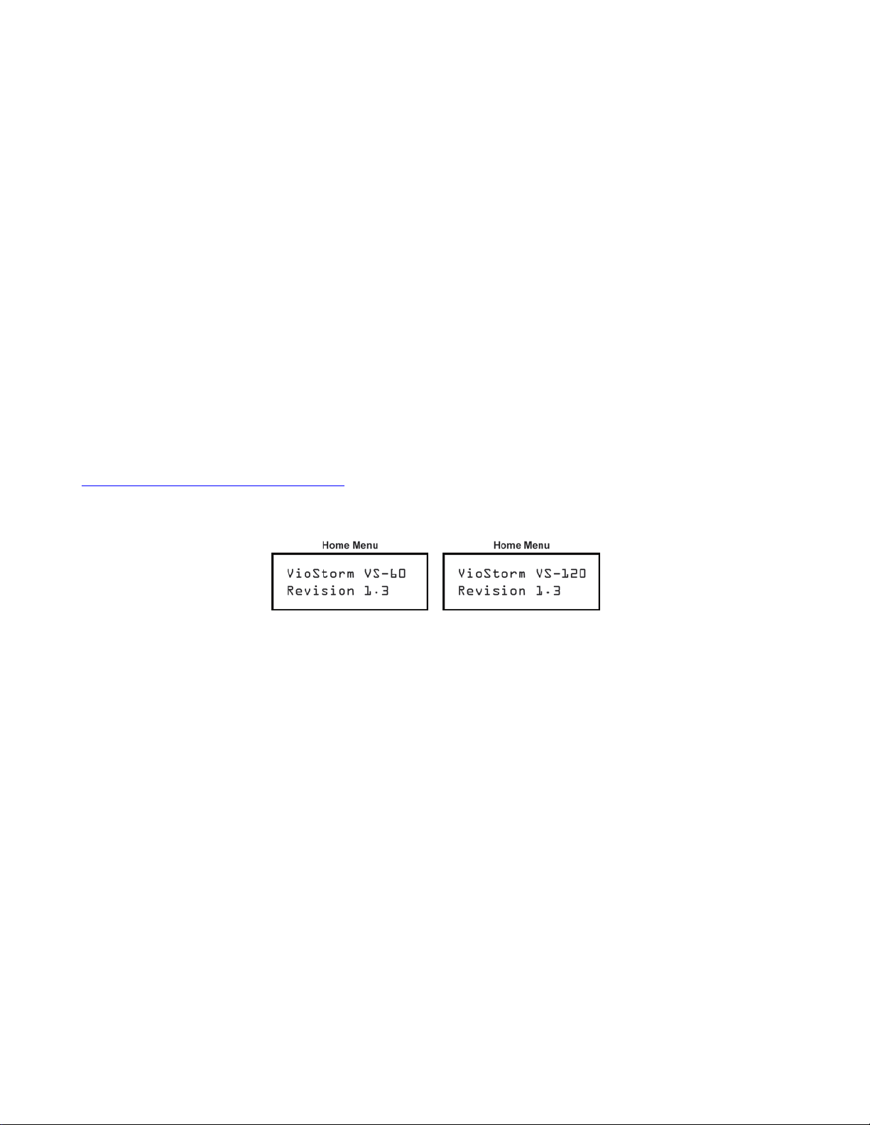
Software Updates
The VioStorm Series control software vers io n is disp la yed on the home menu screen as seen below in Fig.1.
When updates to this software are available they can be downloaded directly from the Wildfire website at:
www.wildfirefx.com/resources/downloads/
group and save it to your desktop. Follow the instructions provided with the download to update the soft ware .
Cleaning
For best performance the fixture fan vents should be kept free of dirt and dust. At no time should any cleaning
chemicals or abrasives be used to clean any part of the fixture. Do not spray or apply any liquid directly to any
part of the fixture. Always unplug the fixture before cleaning. For normal cleaning, a dry soft cloth should be
used to wipe any surface free from dust and light dirt.
Troubleshooting
The fixture will not turn on: – Check to make sure there is power to the fixture. Make sure the power/breaker
switch on the back of the fixture has not been tripped. If you have checked all of the above and the fixture still
won’t turn on, contact Wildfire technical support at (310) 755-6780 or your local distributor
The fixture turns on but there is no UV light output: Make sure the fixture is set to the correct Control Source
setting for your mode of operation. (DMX512 or LOCAL) If you are running the fixture in local mode make sure
the Dimmer menu selection is not turned all the way down. If you are running the fixture in DMX mode, make
sure the dimmer channels on your lighting control device are not all the way down. If you have checked all of the
above and the fixture still won’t turn on, contact Wildfire technical support at (310) 755-6780 or your local
distributor.
. You will need to download the complete bootloader/install program
Fig. 1
11
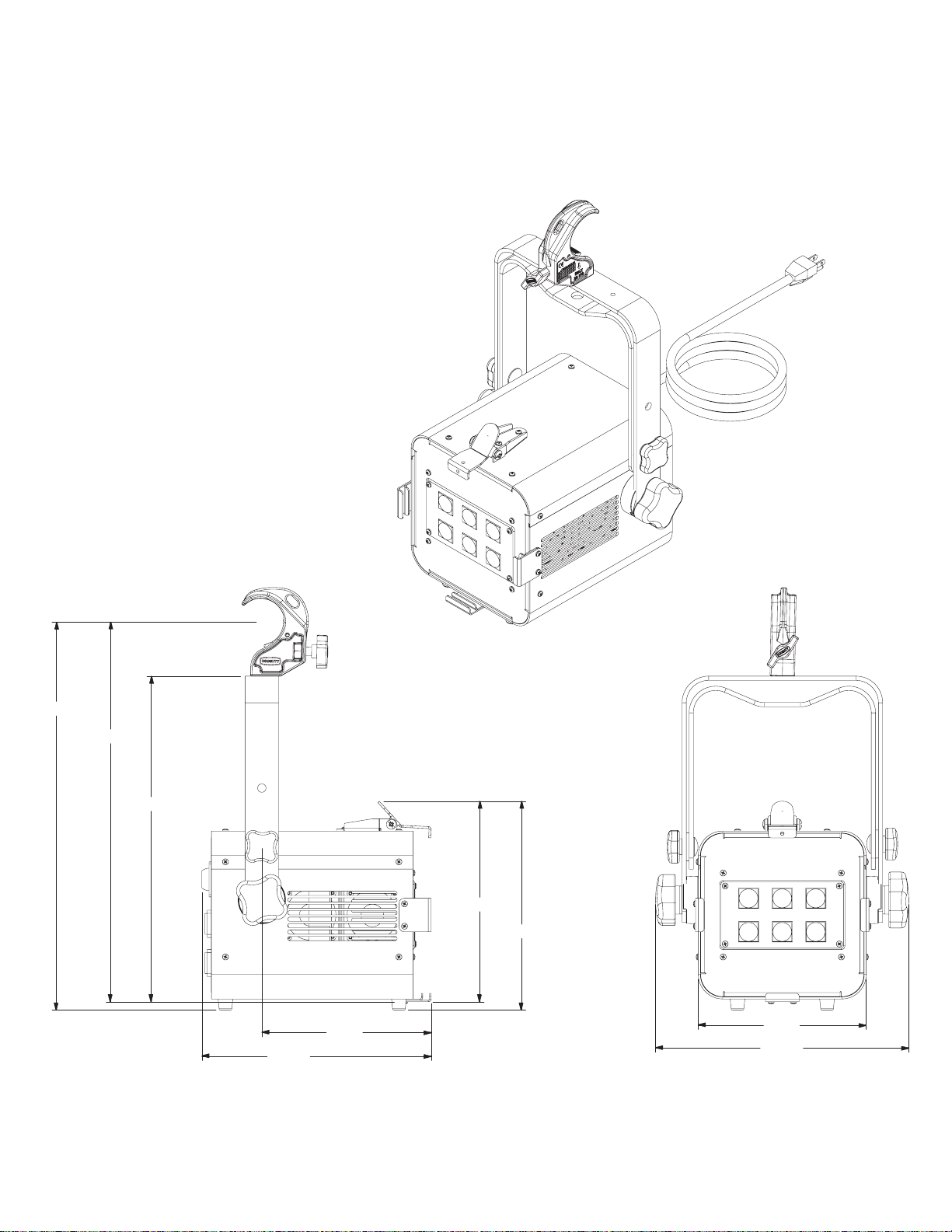
Isometric & Line Views VS-60
Diagrams
17.34
16.97
14.54
901-113-03 VS-60 Line
10.24
7.56
8.96
9.33
7.50
11.31
12
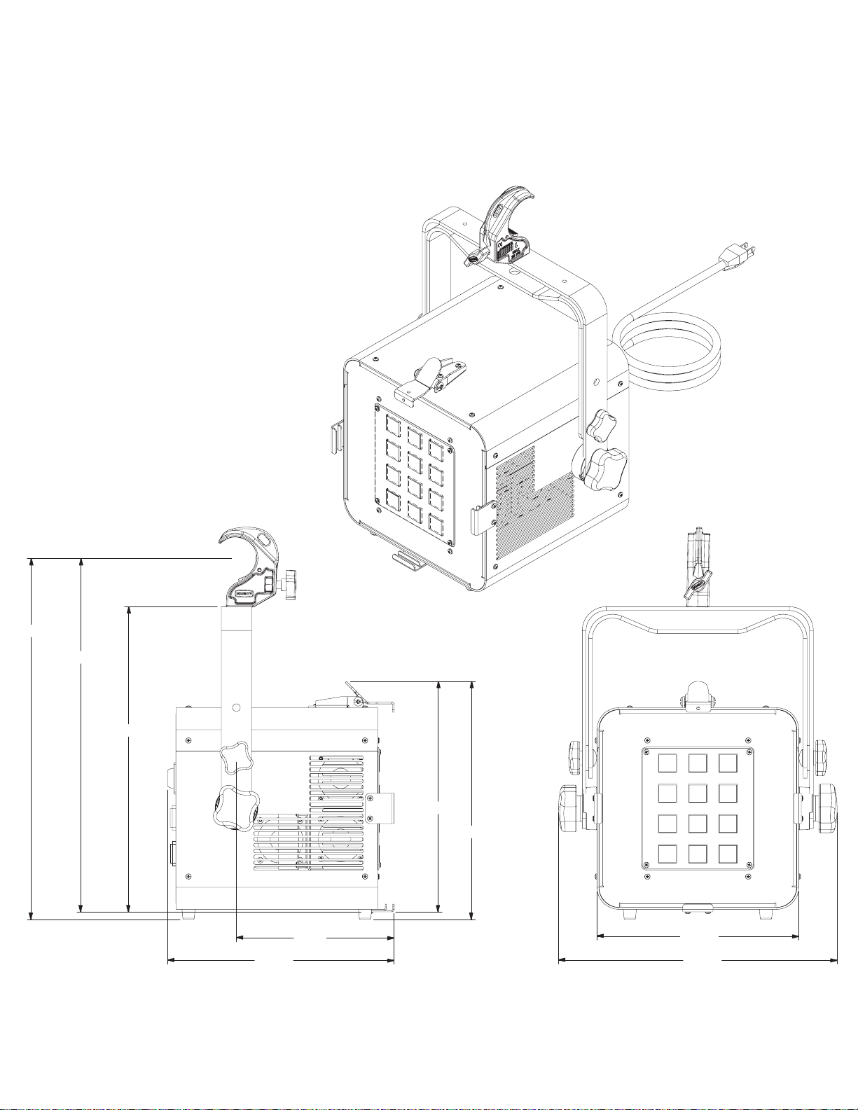
Isometric & Line Views VS-120
Diagrams
17.89
17.51
901-114-01 VS-120 Line
15.12
11.23
7.81
11.43
11.80
10.00
13.81
13
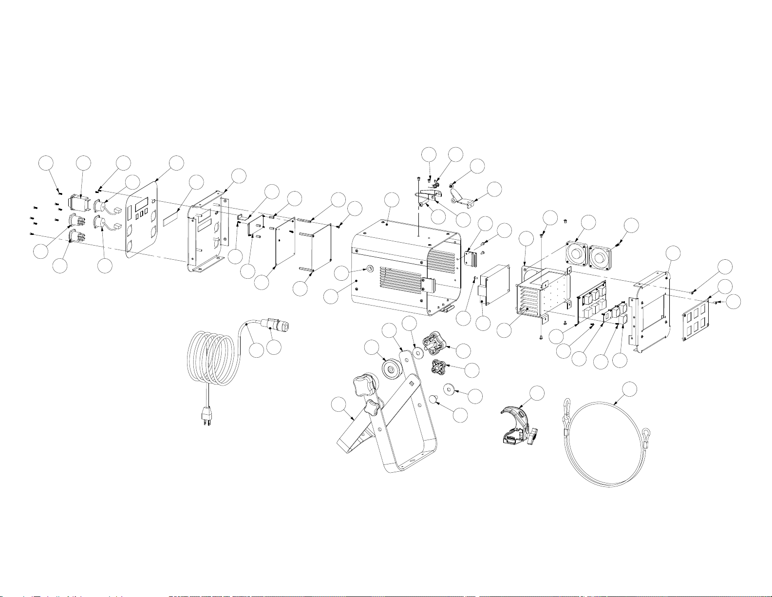
Exploded View VS-60
46 23
39
40
50
19
38
41
10
33
23
36
35
9
8
24
13
26 14
29
47
31
28
12
11
22
30
27
16
45
47
2
44
5
3
32
47
42
1
47
20
4
6
7
22
21
23
34
15
43
47
25
900-113-03 VS-60 Exploded
37
14
17
18
48
49
 Loading...