


USER INSTRUCTIONS
INSTALLATION INSTRUCTIONS
SERVICE INSTRUCTIONS
It is a regulaon that these instrucons be handed to the customer aer installaon is complete. It is
also the responsibility of the installaon engineer to ensure that the customer is able to fully operate
the appliance and is aware of any cleaning or maintenance requirements.
HE900 GAS FIRE
Model number: F-081XX2 for use on Natural Gas (G20) at a supply pressure of 20 mbar in GB / I.E.
(XX denotes Fret Type, Fuel Bed Type & Trim Type)
P-XX1570 ISSUE3
NOTE:
The installaon of this appliance requires a fireplace suite with
specific opening and rebate — See page 8, 9 & 10 for details
This product is not suitable for primary heang purposes.

2
CONTENTS
Regulatory Informaon and Installaon Requirements …………………….. ……. 3
Installaon Requirements (connued) ……………………………………………….….. 4
Methods of Installaon ………………………………………………………………………….. 5
Mantel Crical Dimensions ……………………………………………………………………. 8
Marble Access Cover Dimensions …………………………………………………………... 10
Sing the Appliance ………………………………………………………………………….……. 11
Fixing the Precast Spacer ……………………………………………………………………..… 12
Installing the Fixing Plate (Precast Installaons) ………………………….…………... 13
Installaon of Fixing Plate (Standard Installaons) .………….………………………. 14
Installing the Mantel ……...………………………………………………………………………... 15
Installing the Appliance ……………… ………………………………………………………….. 16
Connecng the Appliance to the Gas Supply …………………………………………. 16
Glass Panel / Front Trim Installaon ……………………………………………………….. 17
Checking Operaon of Appliance ……………………………………………………….…. 18
Spillage Test ……………………………………………………………………………………………. 18
Compleng the Installaon …………………………………………………………………….. 19
Appliance Technical Informaon ………………………………………………………….. 20
Cleaning Instrucons ………………………………………………………………………..… 20
Service Instrucons ……….……………………………………………………………………... 21
User Operang Instrucons …………………………………………………………………… 23
Log Layout Instrucons ………………………………………………………………………….. 24
Product Fiche ………………………………………………………………………………………….. 28
Spare Parts ………………………………...………………………………………………………….. 29
Manufacturers Details ……………………………………………………………………………… 29

3
REGULATORY INFORMATION AND INSTALLATION REQUIREMENTS
THE FOLLOWING MUST BE NOTED PRIOR TO THE INSTALLATION OF THIS APPLIANCE.
This gas appliance MUST be installed by a GAS SAFE registered installer by law. It must be installed in
accordance to these installaon instrucons and the GAS SAFETY (Installaon & Use) REGULATIONS 1998 as
amended. Non compliance of this law may lead to prosecuon and it is in the interest of you and your family
that this condion is observed.
The installaon of this appliance must be in accordance with the relevant parts of the LOCAL AND NATIONAL
BUILDING REGULATIONS as issued by the Department of the Environment or BUILDING STANDARD (Scotland
Consolidaon) REGULATIONS issued by the Scosh Development Department and the following relevant
Brish Standards:
BS5871 Part 2 Installaon of Inset Live Fuel Effect Gas Fires
BS5440 Parts 1 & 2 Installaon of Flues and Venlaon
BS6891 Installaon of Gas Pipe-work
BS6461 Part 1 Installaon of Chimneys and Flues
BS1251 Open Fireplace Components
BS715/BS EN 1856-2 Metal Flue Boxes / Metal Flue Pipes for Gas Appliances
BS EN 1858 / BS1289 Chimneys Components & Concrete Flue Blocks
IS813:1996 Domesc Gas Installaon (Republic of Ireland)
Prior to installaon ensure that the gas supply is compable with the appliance, this appliance must only be
used on natural gas at a supply pressure of 20 mbar as marked on the data plate on the appliance and the
carton.
This appliance must be installed onto a non-combusble surface with a thickness of at least 12mm. See page 8
& 9 for hearth informaon.
This appliance is can be installed into a builders opening which must be constructed of non-combusble
materials confirming to BS1251 or a suitable flue-box complying with the requirements of BS715/BS EN 1856-2.
If the product is being installed into a builders opening the chimney must be at least 3 metres in height and
should be swept before installaon if it has been used for the burning of solid fuel (e.g. coal or wood). The
chimney must only serve as a flue-way to this appliance and must have no openings to any other room. The
opening should be inspected and any exposed brickwork should be repaired where necessary. The chair- brick
(if applicable) should be removed. Ensure that the chimney/flue only serves one fireplace. Remove or securely
fix open any dampers or register plates.
If the product is being installed into a fabricated Flue-box (to BS715) it must be installed onto a noncombusble surface with a thickness of at least 12mm.
This fireplace is also suitable for installaon into precast flue fireplaces which comply to the requirements of BS
EN1858/ BS1289-1:1986 / BS1289:1975 and must have a cross seconal area of at least 12500mm2 for
BS1289:1975 and 16500mm2 for BS1289-1:1986 pre cast flues.
When installing into a precast flue it is extremely important to ensure that the flue is clear of spiders webs and
any other material which could impede the flow of products. Furthermore the flue-way connecng the blocks to
the terminal should be twin skin and preferably insulated to reduce heat loss. If the flue terminates in a ridge
le which is too restricve it may be necessary to change to a less restricve ridge terminal.
It is important to note that pre-cast flue systems should be constructed with an air gap or some form of
insulaon material between the flue block and the plastered face; pre-cast flue systems with a plastered face
directly in contact with the flue block are not correctly installed and installaon of this appliance into such a
flue system may result in the plaster cracking above the appliance.
Essenally a vercal flue route from the spigot is required to ensure evacuaon of combuson products. Any
overhanging brickwork or other building materials which affect the gas from rising to the flue entry should be
removed and made good. For class 1 installaons a throat lintel is recommended.
All flue types should be checked for draw using a smoke bomb or similar, if there is a definite draw then the
installaon of the appliance can proceed. A successful smoke bomb test is not a guarantee that the appliance
will draw properly as it provides a very low volume of smoke. This test is to ensure the flue-way is clear and
connected to the terminal/pot correctly and can help idenfy flue leakage.

4
No purpose made venlaon is normally required for this appliance when installed in G.B. If the appliance is
being installed in I.E then refer to I.S 813:1996 (Domesc Gas Installaon—Naonal Standards Authority of
Ireland). Venlaon areas (if applicable) should be checked periodically to ensure there is no obstrucon, even
though none is normally required for this appliance.
SPILLAGE TEST: A special spillage match holder is provided with this product. Do not remove this spillage tube
from the property—it must remain with the appliance at all mes for future spillage tests.
To check for sasfactory clearance of products of combuson, close all doors and windows and leave the
appliance burning on HIGH for five minutes. Insert the lit smoke match according to the instrucons on page 18,
all the smoke must be drawn into the flue. If spillage occurs allow a further 5 minutes and repeat the test. If
spillage sll occurs turn off the appliance and seek expert advise . If an extractor fan is situated in the room the
spillage test should be repeated with the fan running. If there is a connecng room with an extractor fan the test
should be repeated with all the doors to that room open and the extractor fan running. If the spillage test
connues to fail expert advise should be sought and addional venlaon may have to be provided. SEE PAGE
18 FOR FULL DETAILS ON HOWTHE SPILLAGE CHECK SHOULD BE PERFORMED
This appliance must only be installed onto a suitable hearth* with a minimum thickness of 12mm with an overall
height of 50mm from the floor. The appliance must not be installed directly onto carpet or other combusble
floor materials. The Mantel must have a temperature rang of at least 150oC. Minimum hearth size
requirements are shown on pages 8 & 9.
*If this product is installed as a hole in the wall installaon then no hearth is technically required, however the installer should make
the customer aware of the recommendaons detailed on page 16.
Do not place so wall coverings (i.e. embossed papers etc,) furniture or other combusble items too close to the
fires as they may discolour or scorch.
Do not place or throw rubbish or otherwise onto the fuel-bed.
Do not place any combusble materials or flooring (i.e. carpets etc,) on any part of the hearth.
WARNING: This appliance has a naked flame and/or hot glass surface and as with all heang appliances a
fireguard should be used for the protecon of children, the elderly and infirm. The fireguard should conform to
BS8423 : 2002 (Fireguards for use with Gas Heang Appliances).
Important Note: It is quite normal for a flame effect gas appliance to experience a small amount of soot or
staining to some parts of the fuel effect components. If this becomes excessive it may be because the fuel bed
is not fied correctly—this should be checked according to these installaon instrucons prior to contacng a
service engineer.
It is very important that you arrange for a GAS SAFE registered engineer to service your appliance every year –
during this service the engineer will remove the appliance and check for debris, check the operaon of the flue
and check the operaon of the appliance. This is important for you and your families safety.
NEVER place any rubbish or otherwise onto the fire—this will affect the way the product operates and may
affect the warranty of the product.
NEVER place more ceramic components onto the fuel bed than specified in the instrucons.
NEVER touch the glass or ceramics when the appliance has recently been switched off—these components
retain heat and may cause burns. Leave the appliance to sufficiently cool prior to any contact of the ceramics.
There are THREE methods of installaon which can be employed for this appliance,
mainly dependant upon the fireplace opening type, Class 1 Class 2 or Precast Flue.
The following three pages detail each installaon type.
5
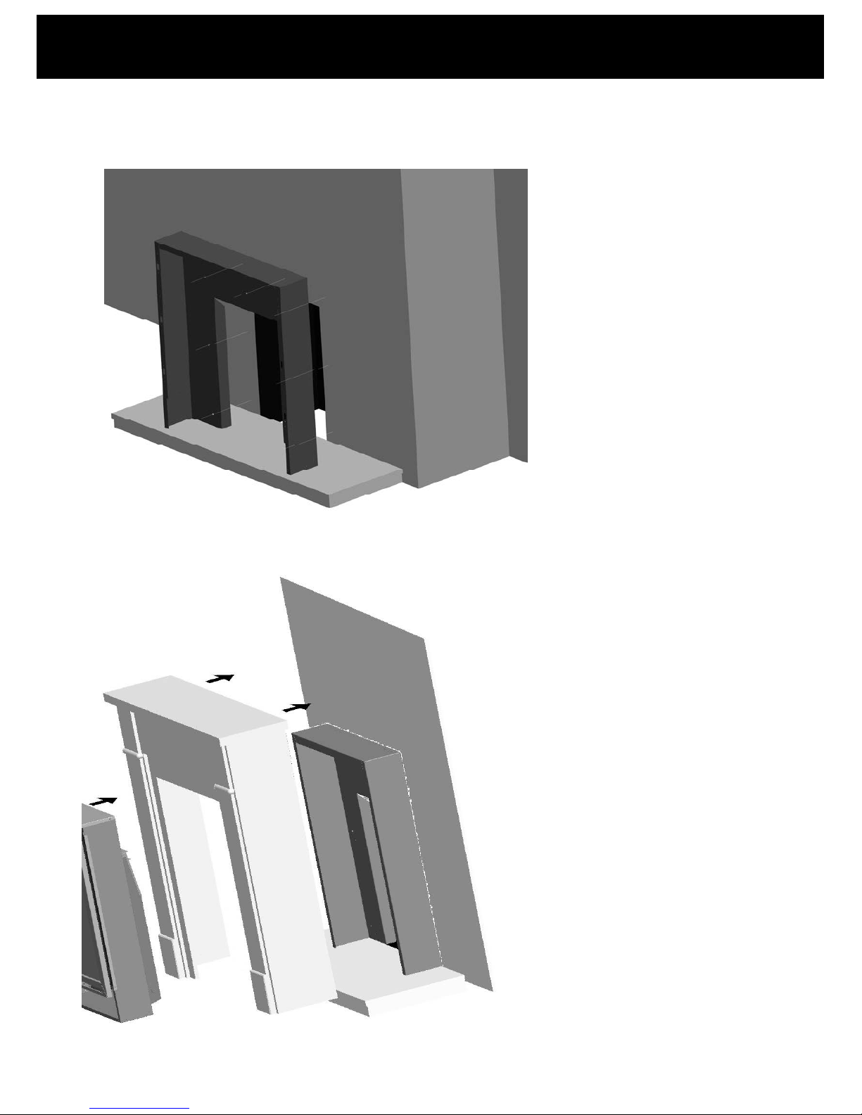
INSTALLATION TYPE A
These diagrams detail the installaon of the appliance into a standard 16” x 22” opening.
This method of installaon is suitable for both Class 1 and Class 2 installaons.
This installaon requires a 900 STANDARD MANTEL. For crical dimensions see page 8.
The 900 FIXING PLATE supplied is firmly
aached to the builders opening aer
the hearth has been installed. Screws
and rawl plugs are provided for this
purpose. For minimum hearth
requirements see page 8.
Using mortar or fondue around the
inside edge of the plate/builders
opening this 900 FIXING PLATE should
be sealed and fixed into place as if it
were a marble back panel. It is
important that no leakage should
occur. See further details on page 14.
Furthermore a suitable high
temperature masc should be used to
further seal around the outside edge of
the 900 FIXING PLATE and the wall.
The TYPE A INSTALLATION is
completed by installing the 900
STANDARD MANTEL to the wall
securely. The mantel should be centred
around the FIXING PLATE.
The crical dimensions of the 900
STANDARD MANTEL are detailed on
page 8. These crical dimensions
ensure that the front trim plate of the
fire and the front face of the mantel
are aligned.
The front trim plate of the appliance is
fully adjustable with four independent
magnets. These magnets can be
screwed in or out to posion the front
trim plate correctly. This adjustment is
provided as there may be some
variaon in the wall flatness and level.
See page 17 for full details regarding
front trim installaon and adjustment.
Ensure the hearth is set level before connuing with
the installaon. Failure to install a level hearth could
affect the installaon of the mantel and appliance.
6
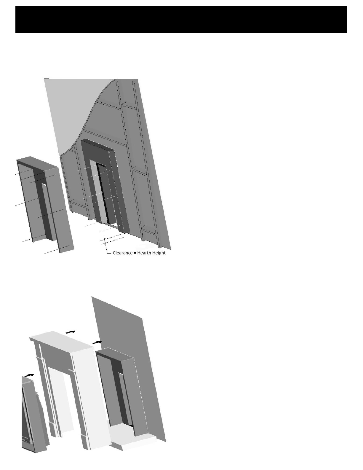
INSTALLATION TYPE B
These diagrams detail the installaon of the appliance into a Pre Cast Flue block and
a 900 STANDARD MANTEL is being fied.
For details on 900 STANDARD MANTEL crical dimensions see page 8
The 900 PRECAST SPACER KIT is used to create an interface
between the precast flue and the 900 FIXING PLATE.
Temporarily fit the hearth and firmly aach the FIXING
PLATE to the wall. See further details on page 12.
Using mortar or fondue around the inside edge of the
SPACER/FLUE should be sealed and fixed into place as if it
were a marble back panel. It is important that no leakage
should occur.
Now remove the hearth carefully to avoid damage whilst the
stud work proceeds.
Timber studding is acceptable providing a 25mm gap is le
around the 900 PRECAST SPACER. Plasterboard the area thus
creang a thin false chimney breast. The front face of the
plasterboard should be around 2-3mm rearward of the front
face of the 900 PRECAST SPACER. Once the area is skimmed
with plaster the surface should be level. For clarity the total
thickness of the false chimney breast should be the same as
the spacer thickness, i.e 55mm.
For minimum hearth requirements see page 8.
The 900 FIXING PLATE is then screwed to the 900 PRECAST
SPACER using the screws provided, then using fire cement or
similar around the inside edge of the joint between the 900
FIXING PLATE and the 900 PRECAST SPACER. Furthermore a
suitable high temperature masc should be used to further
seal around the outside edge of the 900 FIXING PLATE and
the SPACER. See further details on page 13.
It is extremely important that both the 900 PRECAST SPACER
and the 900 FIXING PLATE are sealed to the flue as
essenally a complete fireplace opening. Check the integrity
of the spacer and fixing plate installaon before proceeding.
The TYPE B INSTALLATION is completed by installing the 900
STANDARD MANTEL to the wall securely. The mantel should
be centred around the 900 FIXING PLATE.
The crical dimensions of the 900 STANDARD MANTEL are
detailed on page 8. These crical dimensions ensure that the
front trim plate of the fire and the front face of the mantel
are aligned.
The front trim plate of the appliance is fully adjustable with
four independent magnets. These magnets can be screwed
in or out to posion the front trim plate correctly. This
adjustment is provided as there may be some variaon in
the wall flatness and level.
See page 17 for full details regarding front trim installaon
and adjustment.
Ensure the hearth is set level before connuing
with the installaon. Failure to install a level
hearth could affect the installaon of the
mantel and appliance.
7
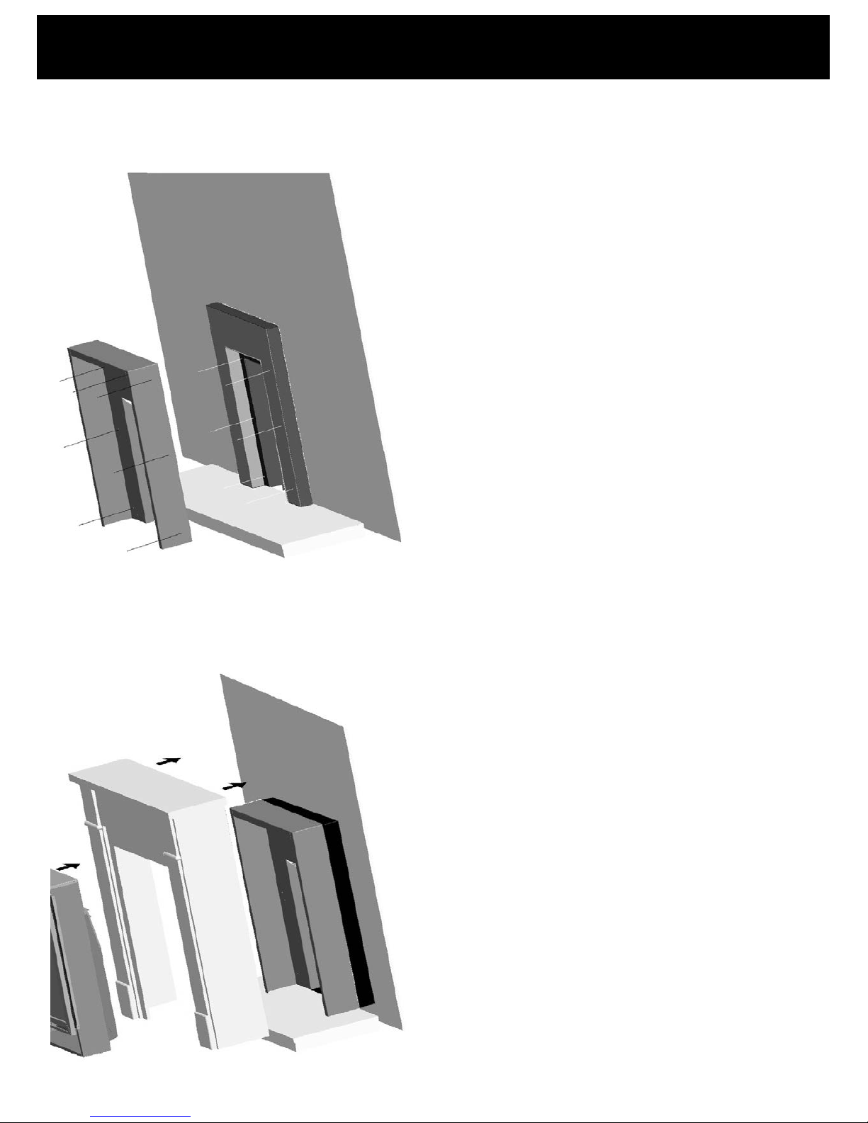
INSTALLATION TYPE C
These diagrams detail the installaon of the appliance into a Pre Cast Flue where a 900 PRECAST MANTEL is being fied
For details on 900 PRECAST MANTEL crical dimensions see page 9.
The 900 PRECAST SPACER KIT is used to create an
interface between the precast flue and the 900 FIXING
PLATE. Fit the hearth and firmly aach the PRECAST
SPACER to the wall. See further details on page 12.
Using mortar or fondue around the inside edge of the
SPACER/FLUE should be sealed and fixed into place as if it
were a marble back panel. It is important that no leakage
should occur.
For minimum hearth requirements see page 9.
The 900 FIXING PLATE is then screwed to the 900
PRECAST SPACER with the screws provided. Using fire
cement or similar around the inside edge of the joint
between the 900 FIXING PLATE and the 900 PRECAST
SPACER. Furthermore a suitable high temperature masc
should be used to further seal around the outside edge of
the 900 FIXING PLATE and the wall. See further details
on page 13
It is extremely important that both the 900 PRECAST
SPACER and the 900 FIXING PLATE are sealed to the flue
as essenally a complete fireplace opening. Check the
integrity of the spacer and fixing plate installaon before
proceeding.
The TYPE C INSTALLATION is completed by installing the
900 PRECAST MANTEL to the wall securely. The mantel
should be centred around the 900 FIXING PLATE.
The crical dimensions of the 900 PRECAST MANTEL are
detailed on page 9. These crical dimensions ensure that
the front trim plate of the fire and the front face of the
mantel are aligned.
The front trim plate of the appliance is fully adjustable
with four independent magnets. These magnets can be
screwed in or out to posion the front trim plate
correctly. This adjustment is provided as there may be
some variaon in the wall flatness and level.
See page 17 for full details regarding front trim
installaon and adjustment.
Ensure the hearth is set level before connuing with
the installaon. Failure to install a level hearth could
affect the installaon of the mantel and appliance.
8
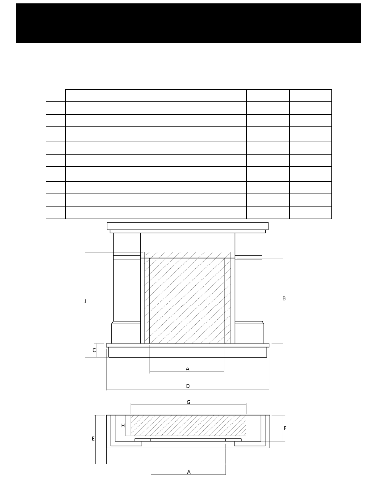
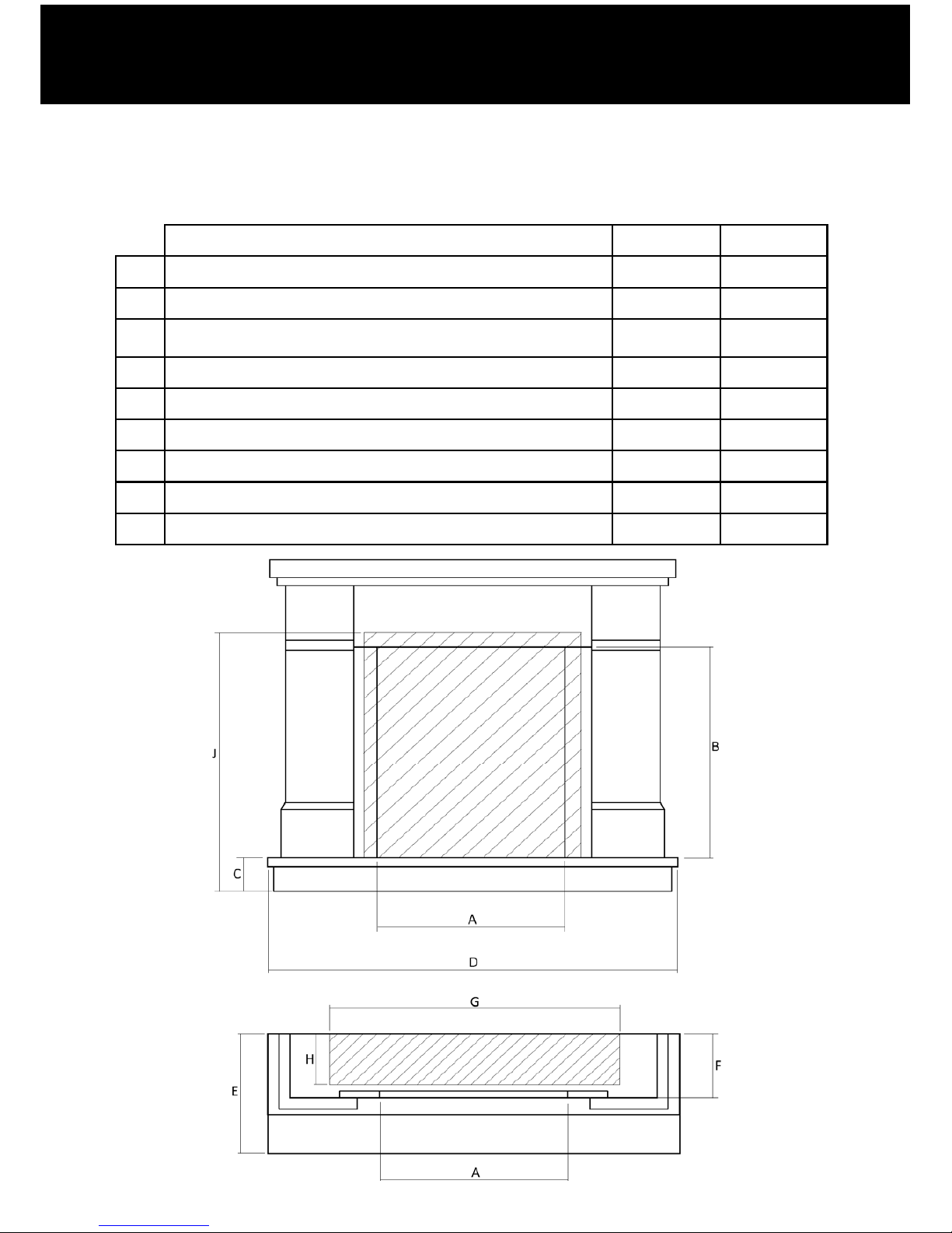
900 STANDARD MANTEL
CRITICAL DIMENSIONS
This Mantel MUST be constructed from Non-Combusble Materials.
These diagrams detail the CRITICAL dimensions which must be achieved for correct installaon
of the appliance when being installed into a 900 STANDARD MANTEL..
NOTE: Front Lower Marble Access Plate Dimensions and installaon for BOTH
900 STANDARD & 900 PRECAST MANTELS is detailed separately on page 10
DESCRIPTION mm (min) mm (max)
A Width of Opening 662mm 664mm
B Height of Opening 744mm 747mm
C Height of Hearth 50mm N/A
D Width of Hearth 960mm N/A
E Depth of Hearth 381mm N/A
F Effecve Rebate to Front Marble Face 164mm 167mm
G FIXING PLATE (Width) Area to be kept clear within Mantel 780mm N/A
H FIXING PLATE Area (Depth) to be kept clear within Mantel 140mm N/A
J FIXING PLATE Area (Height) to be kept clear within Mantel 800mm N/A
9
900 PRECAST MANTEL
CRITICAL DIMENSIONS
This Mantel MUST be constructed from Non-Combusble Materials.
These diagrams detail the CRITICAL dimensions which must be achieved for correct installaon
of the appliance when being installed into a 900 PRECAST MANTEL
NOTE: Front Lower Marble Access Plate Dimensions and installaon for BOTH
900 STANDARD & 900 PRECAST MANTELS is detailed separately on page 10
DESCRIPTION mm (min) mm (max)
A Width of Opening 662mm 664mm
B Height of Opening 744mm 747mm
C Height of Hearth 50mm N/A
D Width of Hearth 960mm N/A
E Depth of Hearth 381mm N/A
F Effecve Rebate to Front Marble Face 219mm 222mm
G FIXING PLATE Area (Width) to be kept clear within Mantel 780mm N/A
H FIXING PLATE Area (Depth) to be kept clear within Mantel 140mm N/A
J FIXING PLATE Area (Height) to be kept clear within Mantel 800mm N/A

10
MARBLE ACCESS COVER
CRITICAL DIMENSIONS
This Access Cover MUST be constructed from Non-Combusble Materials.
These diagrams detail the CRITICAL dimensions of the MARBLE/STONE ACCESS COVER
This informaon is to be used for both 900 STANDARD & 900 PRECAST MANTELS
DESCRIPTION mm (min) mm (max)
A Marble Access Cover Width 659mm 661mm
B Marble Access Cover Height 98mm 100mm
C Chamfer Detail 6mm N/A
A Marble/Stone Access Cover is required to sit below the front trim plate. This Access Cover is used to conceal
the controls area of the appliance and provides access for baery changes or service.
The installer should check that the Access Cover has been made to the correct dimensions and then ensure the
rear face is dry and clean, mark a vercal centre line with a pencil.
Using the two pieces of double sided bonding tape supplied, affix the support plate to the rear face of the Access
Cover.
Ensure that the support plate and the Access Cover are flush at the base and that the two arrow marks are
aligned in the centre of the marble cover (see fig 3 below).
The marble/stone access cover sits on the hearth in front of the appliance.
Use the two adjustable magnets on the appliance to align the front edge of the marble with the mantel.

11
Fireplace Opening
IMPORTANT NOTE: This appliance DOES NOT seal onto a marble or stone back panel. The fire is installed directly into the
FIXING PLATE assembly. Installaon of this fixing plate is detailed on the preceding pages 5,6 & 7.
The mantel should be constructed to the requirements shown on the preceding pages 8,9 & 10.
The fireplace opening should be checked to ensure it meets the dimensional specificaons stated in the diagrams above. It
is also important that the area surrounding the fireplace opening is flat and vercal. If the surface surrounding the fireplace
opening is not flat and vercal then the wall should be remedied prior to the installaon taking place.
The FIXING PLATE (or precast spacer—if applicable) will fit against this fireplace opening, see pages 5, 6 & 7 for installaon
opons. If the fireplace opening is outside these dimensions then the opening should be made good to these dimensions
using a suitable non-combusble material before proceeding.
A flat surface of a minimum 800mm wide and 800mm high must be provided around the fireplace opening to ensure a
good seal is formed between the FIXING PLATE / PRECAST SPACER and the wall. In addion it is important to ensure that
the base of the fireplace opening is flat and level with the hearth surface to ensure a secure and aligned installaon of the
appliance.
The minimum hearth dimensions are shown in the diagrams on pages 8 and 9. The upper surface of the hearth must be a
minimum of 50mm above the floor and the fireplace opening should be filled with a suitable non combusble material to
bring it level with the hearth.
Installaon into a Brick Chimney
When the appliance is being installed into a brick chimney there must be sufficient depth behind the appliance to
accommodate any falling debris. This debris collecon void should be capable of accommodang twelve (16.5) litres of
volumetric space. The flue height must be a minimum of 3 metres.
Installaon into a Prefabricated Twin Wall Metal Flue Box
This appliance can be installed into a prefabricated metal twin wall flue box providing it complies to the requirements of
BS715 / BS EN 1856-2. The box must have an insulated flue with a minimum diameter of 125mm (5”) diameter and a
minimum effecve overall height of 3 metres.
The top outer face of the flue box should be insulated to prevent heat loss with a layer of mineral wool insulaon or similar.
The metal flue box (to BS715) must stand on a non-combusble surface with a minimum thickness of 12mm.
Installaon into a PRE-CAST FLUE Installaon
Ensure that there is a minimum of 115mm from the front of the fireplace opening to the rear of the flue starter block—this
is to ensure that sufficient clearance is allowed for debris collecon. The flue height must be a minimum of 3 metres.
SITING THE APPLIANCE

12
Checking the Flue
Use a smoke pellet prior to the appliance installaon to ensure the viability of the flue and check that the smoke can be seen
being emied from the terminal / chimney pot outside. There must be no leakage of smoke through the structure of the
chimney/flue during or aer the smoke pellet test and it is important to check inside upstairs rooms adjacent to the chimney/
flue. Check the chimney pot / terminal and general condion of the brickwork or masonry. If the chimney or flue is in poor
condion or if there is no up-draught do not proceed with the installaon. If there is a history of down-draught condions
with the chimney / flue, the installaon of a tested and cerficated flue terminal or cowl suitable for the relevant flue type
should be considered.
IMPORTANT NOTE: THIS FIXING PLATE IS INSTALLED
BEFORE
THE MANTEL AND FIRE ARE FITTED
When the hearth has been installed and the fireplace opening is prepared as per the details on page 11 of these instrucons,
the PRECAST SPACER and/or FIXING PLATE can commence.
This appliance MUST be installed with the FIXING PLATE supplied.
If this appliance is being fied into a brick chimney or BS715 fabricated metal firebox then turn to page 14.
FIXING THE PRECAST SPACER
(PRECAST FLUE INSTALLATIONS ONLY)
If the appliance is being installed into a PRECAST flue then follow the procedure below to fix the PRECAST SPACER to the wall.
Using the 10 screws and plugs provided in the PRECAST SPACER kit,
secure the spacer to the wall symmetrically around the hearth / precast opening.
Once screwed into posion ensure this spacer is sealed airght against the fireplace open-
ing with a suitable heatproof silicone externally around the frame and internally using a
non combusble fondant as you would installing a marble back panel.

13
Installing the FIXING PLATE
The FIXING PLATE can now be screwed to the PRECAST SPACER.
Use the 7 screws supplied with the PRECAST SPACER kit to secure as shown above.
INSTALLING THE FIXING PLATE
(PRECAST INSTALLATIONS ONLY )
For Class 1 and Class 2 installaons see page 14.
PRECAST INSTALLATIONS
Once screwed into posion ensure this FIXING PLATE is sealed airght against the PRECAST
SPACER with a suitable heatproof silicone externally around the frame and internally
around the fireplace opening using fire cement or other suitable non combusble fondant
as you would installing a marble back panel.

14
The mantel can now be fied, and the back panel adjusted
into the correct posion.
STANDARD INSTALLATIONS
INSTALLING THE FIXING PLATE
(STANDARD INSTALLATIONS )
Installing the FIXING PLATE
The FIXING PLATE can now be screwed to the wall symmetrically around the fireplace opening and hearth.
Use the 7 screws and plugs supplied in the appliance installaon kit.
Once screwed into posion ensure this FIXING PLATE is sealed airght against the wall with a
suitable heatproof silicone externally around the frame and internally around the fireplace
opening using fire cement or other suitable non combusble fondant as you would installing
a marble back panel.

15
Before fing the shelf to the mantel, the Rockwool
(supplied) should be packed around the PRECAST
SPACER and/or the FIXING PLATE as shown in the
adjacent picture.
Under NO circumstances should this fireplace be
commissioned without the installaon of the
Rockwool provided.
The shelf can now be fied to the mantel.
This appliance is intended for installaon into a
marble or stone mantel constructed of non
combusble material. For this reason no clearances
from combusble shelf are given.
INSTALLING THE MANTEL
(ALL INSTALLATIONS )
Installing the MANTEL
The mantel should be placed symmetrically around the FIXING PLATE . Carefully measure the distance between the
mantel opening and the front edge of the FIXING PLATE to double check. Failure to fit the mantel in the correct
posion will prevent the front trim assembly from fing properly.
Secure the mantel to the wall.

16
Connecng the Appliance to the Gas Supply
In all installaon condions the gas connecon should be provided using 8mm (O/D) copper tubing. No soldered joints should
be used with the firebox of the appliance. The blind grommet which is supplied in the standard fing pack should be used to
close up the knock out hole—simply cut a small cross with a sharp knife in the centre of the grommet—this will then seal
around the gas pipe to provide a ght seal. Under no circumstances should this gas entry hole be le open and unsealed as
this can result in flame reversal and can cause damage to the appliance. Should this occur the warranty to this appliance will
be rendered void.
Before connecng the gas supply to the appliance a gas soundness test should be performed to ensure that the exisng pipe
work in the property is sound.
Ensure that the gas line has been purged to prevent dust or debris from entering the appliance.
The burner tray can now be reinstalled into the firebox using the eight screws — see page 21
The gas connecon should be made to the appliance using the 8mm restrictor isolaon valve supplied with the appliance.
This restrictor elbow is supplied loose and should be fied as per the label on the instrucon packet.
Prepare the Appliance for Installaon
Remove the front trim panel, the glass panel assembly and the ceramic components from the unit (see glass removal
instrucons on page 17).
Remove the burner tray from the appliance. (For instrucons see page 21). Remove the knockout for the gas entry, fit rubber
plug aer sling for gas pipe entry—see below for full details.
Fit the slide lever to the burner tray using the 2 (two) screws provided.
Carefully slide the firebox into the opening. (Note the rubber seal is pre-fied to the appliance on the sealing face).
THIS APPLIANCE CAN BE INSTALLED AS A HOLE IN THE WALL INSTALLATION. FULL DETAILS OF THIS TYPE OF INSTALLATION ARE
SUPPLIED WITH THE HIW INSTALLATION KIT.
THE INSTALLER MUST INFORM THE USER OF THE FOLLOWING IMPORTANT NOTICES AFTER A HOLE IN THE WALL INSTALLATION HAS
BEEN UNDERTAKEN.
1. The user must be made aware to fit a secure fireguard where the room is used by elderly, infirm, infants or young children.
2. The customer should be advised to fit a hearth panel or a physical barrier in accordance with BS5871-2. Should this advice not
be followed the customer should be advised to give due to consideraon to the safety of the occupants in the room where the
appliance is to be installed.
3. The user must be made aware to keep the area immediately in front of the appliance clear of combusbles items. This does
not include the floor covering however such covering should be fixed.
4. The user must ensure that other occupants of the room where the appliance is installed are nofied to not get unnecessarily
close to the appliance when in use or to posion any furniture or appliances too close to the fire.
Fix the appliance into posion using the eight (8) securing
nuts supplied. Note the appliance has slots at these
posions to allow a small amount of movement le or
right to allow it to be secured centrally. See adjacent
diagram.
These nuts need to be fixed using the special magnesed
socket driver (supplied).
UNDER NO CIRCUMSTANCES SHOULD THIS
SOCKET TOOL BE REMOVED FROM THE SITE,
IT WILL BE NEEDED FOR FUTURE SERVICING
OF THIS APPLIANCE.
INSTALLING THE APPLIANCE
INSTALLING THE APPLIANCE AS HIW
(Hole In the Wall)

17
Removal and replacement of the front glass panel.
The glass panel is held in place with 10 screws. When
removing the screws it is advised to remove the side screws
first, and finally the top two screws. Take care to hold the
glass panel whilst removing the final screw.
Take care to support the glass and the frame when removing
or handling the glass assembly.
Now li the glass frame assembly from the appliance.
The ceramics can now be installed, rearranged correctly or
removed for service. For correct installaon of ceramics see
pages 24-27.
Refit the glass frame assembly in the same manner.
The glass panel should be undamaged. If the glass panel is
broken or cracked it should not be used. Contact the
manufacturer for a suitable replacement before connuing.
Installaon / Removal of the Front Trim.
Fit the marble/stone access cover into posion. See
page 10.
The front trim can now be fixed to the appliance.
Place the lower edge into posion on top of the marble
access cover ensuring the control lever pokes through the
lower slot in the trim. Now rotate into posion. The front
face of the trim should be in line with the front of the mantel
and access cover.
Correct alignment can be achieved by removing and adjusng
the 4 (four) screw magnets on the trim.
The gap between the top of the trim and the mantel can also
be adjusted using the two thumb screws at the base of the
trim. See above.
It is important to leave about 1-2mm above the
trim as expansion will take place while the
appliance is hot.
GLASS PANEL / FRONT TRIM INSTALLATION
Adjustment of the Front Trim.
The front trim has various adjustment features to allow it to
sit in the correct posion.
On the rear of the trim are 4 (four) screw in magnets. These
magnets sit on the glass frame and can be adjusted to align
the front face of the trim with the front face of the mantel.
At the lower edge of the trim there are two thumb screws
which can be wound in and out to set the height of the trim.
These screws will sit on the marble access cover and create a
small gap in this area. Subsequently this will control the gap at
the top of the trim/mantel.

18
Install the ceramics into the appliance according to these instrucons—see pages 24 through to 27.
Refit the glass panel and front trim cover—See page 17
Test the operang pressure of the appliance by aaching a pressure gauge to the test point of the appliance. This connecon
should take place when the appliance is OFF. Ensure that gas is turned on at the gas meter and purge the air from the
appliance. To light the appliance follow the instrucons below:
Slide the control lever fully to the (IGN) posion and hold. The spark generator should spark connuously, ensure the
spark is being generated correctly at the pilot assembly. Connue with this procedure unl the air is purged from the
appliance and the pilot and main burner are lit. Once lit hold the lever pushed to the le for up to a further 10-15 seconds.
Once the pilot is established and secure release the lever—this is now the (LOW) posion. Now slide the lever to the right
to the (HIGH) posion. Allow the appliance to run for a minimum period of 5 minutes. Next check that the inlet pressure to
the appliance is 20 mbar ±1 mbar. Move the lever to the right against the spring pressure to the posion to turn OFF.
When lighng this appliance it should be noted that the main burner will light at low rate during the pilot ignion process.
To check for sasfactory clearance of products of
combuson, close all doors and windows and leave the
appliance burning on HIGH for five minutes.
Insert a lit smoke match into the match holder supplied,
poinng the match to the right as shown.
Push the holder and match into the centre slot at the top
of the appliance. Once fully in, the holder should be
rotated 90 degrees
Now move the match holder to the le side of the slot
AS FAR AS POSSIBLE. This will posion the smoke match
at the internal dra diverter.
If some smoke appears at the convecon outlet it may
be the smoke match is not close enough to the diverter.
Move the holder slightly to the right and rotate the
holder a lile further clockwise.
DO NOT MOVE MATCH HOLDER FROM THIS POSITION
UNTIL THE SPILLAGE CHECK IS COMPLETE.
SPILLAGE TEST
Check the clearance of combuson products. It is important to note that a special match holder is provided with
this appliance. Do not remove this item from the property aer installaon is complete—it will be required for
future inspecons. If this part is lost contact the manufacturer immediately to purchase a replacement.
All the smoke must be drawn into the flue. If spillage occurs allow a further 5 minutes and repeat the test. If spillage sll occurs
turn off the appliance and seek expert advice. If an extractor fan is situated in the room the spillage test should be repeated
with the fan running. If there is a connecng room with an extractor fan the test should be repeated with all the doors to that
room open and the extractor fan running.
This appliance is fied with an atmospheric sensing system in the form of an oxygen sensing pilot burner. This is designed to
shut the fire off in the event of products being spilled into the room where the fire is being operated. It is important to note
that this spillage monitoring device should not be disabled or be adjusted by the installer. If the spillage monitoring device
(O.D.S pilot) is replaced it must only be exchanged with a suitable component which is supplied by the manufacturer.
1
2
3

19
THE INSTALLER MUST INFORM THE CUSTOMER OF THE FOLLOWING TO COMPLETE THE INSTALLATION
Demonstrate the lighng of the appliance and the controls to select the heat sengs. Demonstrate how to exnguish the
fire.
Demonstrate the removal of the trim and marble access cover and how to reinstall correctly.
Demonstrate the locaon of the baery igniter and how to replace the baery. (AA type)
Discuss the removal and reinstallaon of the glass and the ceramics. Explain how they should be cleaned and make the
customer aware of the health and safety warning detailed on page 20.
Explain to the customer that the ceramics are fragile and must be treated with great care, explain that the ceramics are
not covered by the warranty because of their fragility. Also explain that small hairline cracks will appear in the surface of
the ceramics due to heat expansion and contracon—this is perfectly normal.
During the first several hours of use an odour will be experienced—this is normal and is the starch used in the
manufacturing of the ceramic fuel bed, paints curing and oils remaining on some metal components that will burn off. This
odour is non toxic and will eventually disappear aer a few hours of use.
Advise that no rubbish should be thrown onto the appliance and that the appliance should be cleaned regularly.
Advise that the glass panel is very hot when running and that the trim and/or marble access cover should not be removed
unl the appliance has been allowed to cool for at least 30 minutes.
A vacuum cleaner should be used to regularly clean behind the marble access cover to prevent lint gaining access to the
appliance, in parcular the pilot.
Advise the customer that the appliance should be serviced annually by a GAS SAFE engineer to ensure the safety and
integrity of the appliance.
Advise the customer that the appliance has a very hot surface and therefore it is essenal that a suitable fireguard be used
for the protecon of the elderly, infirm and young children. This fireguard should conform to BS8423 : 2002 (Fireguards for
use with Gas Heang Appliances).
These instrucons must be handed over to the customer once installaon is complete.
COMPLETING THE INSTALLATION

20
Appliance Technical Informaon
Gas Type : Natural Gas Category : I2H Inlet Pressure: (Cold) 20mbar
Heat Input Gross : 6.75kW Injector : 74 Desnaon Countries : GB/ IE
Efficiency Class: 1 NOx Class: 5 Efficiency Net: 83%
HEALTH AND SAFETY NOTICE
This appliance uses fuel effect pieces manufactured from Refractory Ceramic Fibres (RCF). Care must be taken to avoid
excessive exposure to these materials as they may cause irritaon to the eyes, skin, nose and throat. When handling, avoid
inhaling and contact with skin and eyes. It is recommended that disposable gloves are worn in addion to a facemask and
eye protecon. Aer handling, wash hands thoroughly and any other exposed parts which may have come in to contact
with the material.
If a vacuum cleaner is used to clean the fuel bed or areas around the appliance where fragments of the material may have
fallen it is recommended that it be of the type fied with a HEPA filter.
Care should be taken when disposing of RCF materials. It is important to keep any dust to a minimum so it is recommended
that the fuel effect components are placed into a heavy duty plasc bag. The bag should be clearly labelled RCF WASTE.
These materials are not classified as hazardous waste and should be disposed of at a site approved for the disposal of
industrial waste.
Maintenance of the Appliance
The following procedures can and should be performed by the customer at regular intervals depending upon use of the
appliance.
Cleaning the Appliance
Fuel Bed
The fuel effect components supplied with this product are extremely fragile and must be handled with great care. The
ceramics in this appliance are not covered by the warranty due to their fragility. This includes the RCF fibre boards in the fire
box. These components will break or chip if not handled with the greatest of care.
Cleaning of these components should only be undertaken once the appliance is switched off and has been allowed to cool
for a minimum period of one hour. The components should be lied carefully piece by piece from the appliance and placed
onto a dust sheet or similar. They can be brushed gently with a so brush to remove any dust or deposits. If you intend to
use a vacuum cleaner then this should only be done once the loose Rockwool and any loose deposits of soot etc. have been
removed. Ensure that the moulded components are structurally sound and no significant part of the moulding has broken
away. If any component has broken then it should be replaced before using the appliance. Only the correct replacement
part as supplied by the manufacturer shall be used in this appliance. Do not add any addional components to the fuel bed
layout. It is important to note that small hairline cracks will appear in the surface of the ceramics due to heat expansion and
contracon—this is perfectly normal.
Painted Metal Parts and Glass
It is important that no abrasive cleaners or chemical agents are used in the cleaning of these components. It is
recommended that all these surfaces including the painted metal parts are cleaned with a clean damp (not wet) cloth.
Cleaning should only take place when the appliance is switched off and has been switched off for a minimum period of one
hour. The glass panel can be cleaned using a non abrasive glass cleaner—this must only be undertaken when the appliance
is off and cold.
Pilot
The pilot to this appliance has a small aeraon hole at its base. If lint hair or excessive dust
blocks this hole it may cause nuisance shutdown of the appliance. This aeraon hole can
be cleaned using a thin nozzle on a vacuum cleaner. Apply the nozzle of the vacuum
cleaner over the aeraon hole and use thumb and forefinger to help seal against the pilot
body to provide maximum sucon. This procedure should only be undertaken when the
appliance is off and cold. If excessive lint is drawn in through this hole due to infrequent
cleaning then it may result in the appliance not lighng or turning itself off automacally
due to a starvaon of air at the pilot burner. If this procedure does not resolve such a
problem then the pilot assembly will need to be replaced. This must involve the
installaon of the same part as supplied by the manufacturer. Excessive lint build up
which results in appliance operaonal problems is not covered by warranty. It is important
to ensure that the area behind the marble access cover is cleaned regularly to prevent this
occurrence (once a month during the winter period).

21
The following procedures can and should only be performed by a GAS SAFE registered installer.
This appliance should be serviced annually by a GAS SAFE registered installer.
Removal / Replacement of Gas Carrying Components.
The removal and replacement of all the gas carrying components will require the removal of the burner tray. The
following informaon details the removal of this tray. Once removed, refer to the relevant secon that follows detailing
the removal of the specific component (s).
Remove the marble access cover and the front trim from the appliance.
Turn off the gas supply at the isolaon valve on the appliance. Ensure the appliance is cold.
Remove the glass panel (as described on page 17)
Remove the fuel effect components - put in a suitable locaon where they cannot be damaged.
Disconnect the gas supply from the restrictor elbow.
Remove the six (6) screws (shown below) and the two (2) screws behind the burner securing the burner tray to
the firebox as detailed in the diagram.
SERVICING THE APPLIANCE
Now carefully pull the burner tray from the fire box. The burner tray can now be serviced or repaired
accordingly—see the following pages for informaon about removing and replacing serviceable components.
Important Note: Check the ceramic gasket located around the edge of the firebox where the burner tray was
seated. Ensure this gasket is in good condion prior to reinstallaon. If damaged, this gasket should be replaced.
See page 28 for part no. manufacturer’s details.
Re-assemble the tray in the reverse order.

22
Removal / Replacement of Gas Carrying Components (connued)
Slide Control Valve
1. Remove the locknut from the front of the valve.
2. Undo the three (3) nuts around the periphery of the valve body—Gas Inlet / Burner / Pilot.
3. Remove the thermocouple nut from the back of the valve.
4. The valve can be removed and serviced / replaced as necessary.
5. Re-assemble in reverse order.
6. Re-assemble the burner tray into the firebox (see previous page).
Replacement of the Pilot
1. Undo the pilot gas supply from the base of the pilot.
2. Remove the thermocouple nut from the back of the valve.
3. Remove the HT lead from the electronic igniter unit.
4. Remove the two (2) screws securing the pilot to the burner
tray.
5. Remove the two (2) screws securing the microswitch to the
tray.
6. The pilot assembly can be removed and replaced.
7. Re-assemble in reverse order.
8. Re-assemble the burner tray into the firebox (see previous
page).
Replacement of the Injector
1. Remove the brass nut from the injector elbow.
2. Unscrew the injector elbow from the burner assembly.
3. The injector can be removed and replaced.
4. Re-assemble in reverse order.
5. Re-assemble the burner tray into the firebox (see previous page)
Only replacement components supplied by the manufacturer should be used in the service of this appliance.
Contact details for Hearth Products Ltd can be found on the back page of these instrucons.

23
SLIDE CONTROL OPERATION
1. Push the control lever to the le to the IGN symbol . The spark generator should cause a repeve spark at the
pilot and the pilot and main burner should ignite. If the pilot does not light aer 10 seconds then slide the control
lever to the right towards the OFF symbol and wait for 3 minutes.
2. Once the pilot and main burner are lit keep the control lever held In this posion for up to 15 seconds. Before
releasing the lever give a firm push to the le to ensure the valve is engaged.
3. Now slowly release the control lever to the symbol, the pilot should remain lit and the burner will be in the
LOW seng. If it goes out, slide the lever to the OFF symbol and wait for 3 minutes. Then return to step 1.
4. To set the appliance to the HIGH seng, move the control lever to the right to the flame symbol. A stop will be
felt at this posion.
5 It is also possible to adjust the control knob between the and the flame symbols to achieve mid sengs.
6 To turn the fire off, push the lever to the right to the symbol to turn off.
IMPORTANT NOTE: Should the spark generator fail to provide a spark at the electrode it may be that a small amount of
soot has fallen from the fuel bed onto the pilot assembly, causing a short circuit. If this is the case, ensuring the
appliance is off and cold, this area can be cleaned with the thin nozzle from a vacuum cleaner—see previous pages to
remove trim / glass and logs. Alternavely check the baery is in good condion—the baery access cover is at the base
of the appliance just le of centre and can be accessed by removing the front trim and marble access cover.
When lighng slide control appliances it should be noted that the main burner will light at low rate during the
pilot ignion process.
OPERATING INSTRUCTIONS

24
FUEL BED LAYOUT
The following instrucons detail how the Rockwool, ceramic fuel bed and loose components are to be
installed onto the appliance. Great care should be taken when handling these ceramic parts as they are fragile
and can easily be broken. Do not force any component into posion, if it does not fit easily then you are not
fing the part correctly. These instrucons can also be followed to remove or reinstall the fuel bed aer
cleaning. This is a procedure that can be undertaken by the customer as required and the frequency will be
depend upon use. See page 17 for glass panel removal and installaon.
Step 2
Fit the front ceramic rail strip in front of the burner as shown in the picture below.
Step 1
Fit place some of the Rockwool onto the surface of the burner in the posions shown in the picture
Step 3
Fit the large rear log A into the appliance as shown in the picture below.

25
Step 4
Fit Log B onto the burner locaon brackets as shown below.
Step 5
Fit Central Log C onto the fuel bed as shown in the picture below.

26
Step 6
Fit Log D onto the fuel bed as shown in the picture below.
Step 7
Fit Log E onto the fuel bed as shown in the picture below.

27
Step 8
Fit Log F onto the fuel bed as shown in the picture below.
Step 9
Fit Log G onto the fuel bed as shown in the picture below.
Now refit the glass panel, front trim and marble access cover—see page 17 for details

28
Important Note:
The energy efficiency class of this product is defined using a seasonal efficiency calculaon which reduces the actual
net efficiency of the product where the use of automated heat control, thermostats, window open sensors and
mers are not used. This is not to be confused with the net efficiency, or useful efficiency of the appliance (shown in
the tables above).
This product MUST be installed by a Gas Safe Registered Installer. Full details are provided in this manual.
Hearth Products Ltd. Unit 14 Tollgate Industrial Estate, Stafford, ST16 3SU
Product Fiche
Manufacturer : Hearth Products Ltd
Model No. F-081XX2
Fuel Type Natural Gas I2H
Energy Efficiency Class D
Indirect Heang Funconality No
Direct Heat Output kW 5.1kW
Indirect Heat Output kW N/A
EEI 74%
Useful Energy Efficiency (NCV) High : 83.0%
Useful Energy Efficiency (NCV) N/A
Nominal Heat Output High : 5.1kW
Nominal Heat Output Low : 2.1kW
Heat Output Temperature Control Two Manual Stages
Permanent Pilot Power (kW) N/A
Space Heang Emissions NOx (GCV) 130mg/kWh

29
User Replaceable Parts
Part Number Descripon
P-XX1191 Ceramic Front Rail
P-XX1191A Ceramic Rear Log A
P-XX1191B Ceramic Centre Log B
P-XX1191C Ceramic Log C
P-XX1191D Ceramic Log D
P-XX1191E Ceramic Log E
P-XX1191F Ceramic Log F
P-XX1191G Ceramic Log G
P-XX1191Z Ceramic Gasket Seal for Burner Tray (See page 21)
P-XX1191H Pack of Glow Rockwool
P-XX1398A Glass Panel with frame assembly
P-XX1398B Front Black Trim Assembly
Due to our policy of connual product improvement, some diagrams and small details may not be accurate however if there is any
concern or maer of understanding that you feel needs to be clarified please contact us directly. Our contact details are shown above.
Hearth Products Ltd
Unit 14 Tollgate Industrial Estate,
Stafford, ST16 3SU
www.hearthproducts.co.uk
Tel: 01785 225401 Fax: 01785 225501
Email: info@hearthproducts.co.uk
 Loading...