

Page 1
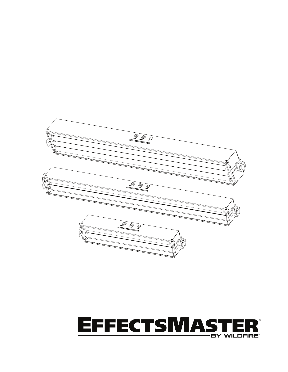
Operation Manual
Ultraviolet LED Lighting Fixtures
EM-44L
EM-42L
EM-22L
Page 2

Table of Contents
Introduction 3
Safety Information 3
Specifications 4
Setup and Operation 5
Unpacking 5
Optional Accessories 5
Setup 5
Maintenance & Troubleshooting 6
Lamp Replacement 6
Cleaning 6
Troubleshooting 6
Diagrams 7
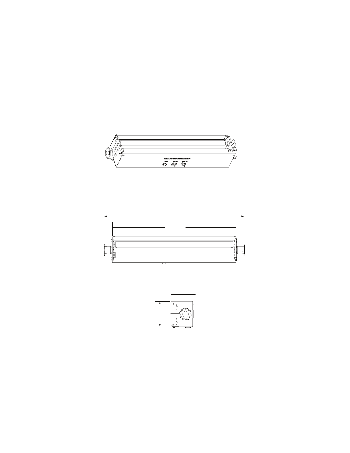
Isometric & Line Views EM-22L 7
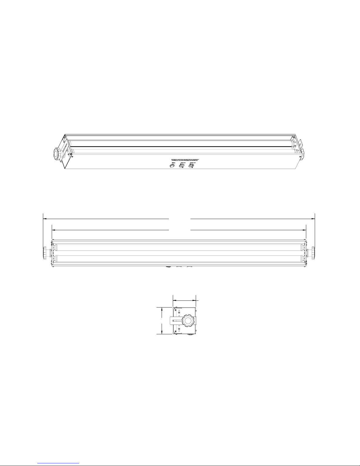
Isometric & Line Views EM-42L 8
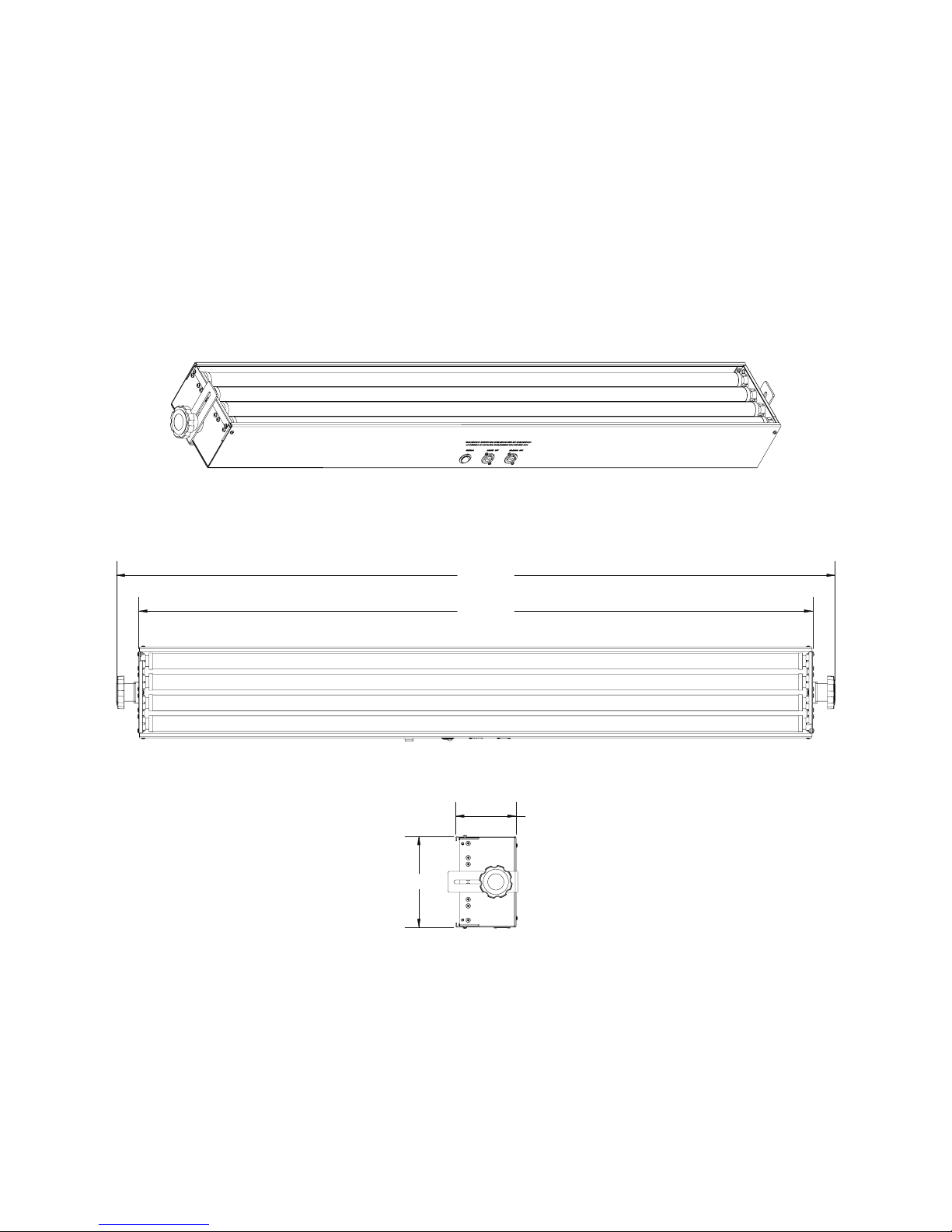
Isometric & Line Views EM-44L 9
Exploded View & Part List EM-22L 10
Exploded View & Part List EM-42L 11
Exploded View & Part List EM-44L 12
Schematic EM-22L 13
Schematic EM-42L 14
Schematic EM-44L 15
Spectral Output Graph 16
Photometrics Chart 16
Limited Warranty 17
2
Page 3

Introduction
Congratulations on your purchase of an Effects Master LED Series Fixture by Wildfire. These powerful and
versatile ultraviolet LED lighting fixtures f eature Wildfire’s SableLE D UV LED tube lamps . Each Effects Master
LED Fixtur e is prec ision en gineered to provide you wit h years of trouble free ser vice. Pl ease tak e a mom ent to
read this manual thorough ly before attempting to operate this fixtur e. Improper set-up, use or servicing m ay
cause damage to the fixture and/or lamps and void the unit’s warranty.
Safety Information
DANGER – RISK OF ELECTRIC SHOCK OR FIRE - USE ONLY WILDFIRE SABLELED LED TUBE LAMPS
MODEL L30T9/BLB (4’) AND L15T9/BLB (2’). DO NOT INSTALL FLUORESCENT LAMPS IN THIS FIXTURE.
WARNING - THIS FIXTURE EMITS ULTRAVIOLET RADIATION (UV) AT A PRIMARY WAVELENGTH OF
365NM, AVOID EYE AND SKIN EXPOSURE AT DISTANCES SHORTER THAN 3.3’ (1m). DO NOT LOOK
INTO THE LAMPS DIRECTLY AT DISTANCES SHORTER THAN 11’ (3.3m) OR VIEW THE LAMPS
DIRECTLY WITH OPTICAL INSTRUMENTS THAT MAY CONCENTRATE THE LIGHT/RADIATION OUTPUT.
CAUTION – WHEN USED IN ACCORDANCE WITH THE MANUFACTURERS OPERATING INSTRUCTIONS,
NO HAZARDS EXIST TO MOST PEOPLE AT DISTANCES GREATER THAN 11’ (3.3m) FROM THE FIXTURE.
HOWEVER, INDIVIDUALS SUFFERING FROM A RANGE OF SUNLIGHT EXPOSURE DISORDERS,
APHAKIC AND PSEUDOAPHIKIC, OR THOSE INDIVIDUALS RECEIVING PHOTOSENSITIVE MEDICATION
MAY RECEIVE DISCOMFORT IF EXPOSED TO ULTRAVIOLET LIGHT.
CAUTION – NOT FOR RESIDENTIAL USE. DRY INDOOR LOCATIONS ONLY. SUITABLE FOR SURFACE
MOUNTING ONLY.
Designed, Engineered and Built in the USA
3
Page 4

H
ousing:
Finish:
Mounting:
Reflector:
Sockets:
Input Voltage:
Input Current:
Frequency:
Power Factor:
Power Consumption:
Operating Temperature:
Humidity:
Power Cord:
Power Connections:
Power Linking:
Lamps:
Peak Wavelength:
Beam Angle:
Lamp Life:
Dimensions:
Weight:
IP Rating:
Warranty:
Standard Equipment:
Optional Accessories:
16 Ga. Rolled steel with stainless steel hardware
Flat black powder coat
Two fully adjustable L brackets
Polished Everbright aluminum 165°
EM-22L: Four positive locking medium Bi-Pin G13
EM-42L: Four positive locking medium Bi-Pin G13
EM-44L: Eight positive locking medium Bi-Pin G13
100-240VAC
EM-22L: 0.30A Max
EM-42L: 0.57A Max
EM-44L: 1.14A Max
50-60Hz
0.99
EM-22L: 30W
EM-42L: 60W
EM-44L: 115W
14° F to 95° F (-10° C to 35° C)
0-95% non-condensing
6’ 16/3 SOW with PowerCON 1 in and male Edison
Neutrik PowerCON 1input and output
EM-22L:
EM-42L: 15 units at 120VAC
EM-44L: 10 units at 120VAC
EM-22L: Two Wildfire SableLED L15T9/BLB UV L ED Tube Lamps
EM-42L: Two Wildfire SableLED L30T9/BLB UV LED Tube Lamps
EM-44L: Two Wildfire SableLED L30T9/BLB UV LED Tube Lamps
365nm
120°
40,000 Hrs
EM-22L: 4.25”/10.79cm High x 5.00”/12.44cm Wide x 27.37”/69.52cm Long
EM-42L: 4.25”/10.79cm High x 5.00”/12.44cm Wide x 51.37”/130.48cm Long
EM-44L: 4.25”/10.79cm High x 6.50”/16.51cm Wide x 51.37”/130.48cm Long
EM-22L: 7.60 lbs./3.44kg.
EM-42L: 15.35 lbs./6.96kg.
EM-44L:
IP-20 Indoor use
Three Year Parts and Labor
Wildfire SableLED UV LED Tube Lamps, Adjustable Mounting Brackets, Power Cord, PowerCON Power Out Cable Connector
T
Safety Cable (147-002)
Floor Mount (147-006)
T-Bar Ceiling Mount (147-003)
30 units at 120VAC
18.20 lbs./8.25kg.
wenty Clamp (147-021)
Specifications
4
Page 5

Setup & Operation
Unpacking
Unpack the fixture and carefully inspect it for any signs of physical damage. Report any damage to Wildfire or
your local distributor immediately. Included with each unit should be the following items:
1. Power Cord
2. PowerCON power output cable connector (used to power link additional fixtures)
3. Operation Manual
4. Warranty Card
Optional Accessories:
Twenty Clamp – These clamps when attached to both of the fixtures adjustable mounting brackets allows you
to mount the fixture to a standard 2” pipe truss. Contact Wildfire or your local distributor for pricing.
Safety Cable- This cable is to be used when installing the fixture on a pipe truss with the Twenty Clamps. It
attaches to the adjustable brackets on the sides of the fixture securing it from falling if the clamp is not tightened
properly. Contact Wildfire or your local distributor for pricing.
Floor Mount Kit- This aluminum stand set enables you to mount your fixture on the floor for footlight
applications. Contact Wildfire or your local distributor for pricing.
T-Bar Ceiling Mount- These brackets enable you to mount your Effects Master fixture to the t-bars in a
standard drop ceiling. Contact Wildfire or your local distributor for pricing.
Setup
Connect the blue PowerCON connector on the power cord to the blue PowerCON AC Input receptacle on the
fixture. The fixture is also provided with a gray PowerCON AC Output receptacle, enabling you to interconnect
power between fixtures. Do not interconnect more than ten model EM-44L, fifteen model EM-42L or 30 EM-
22L fixtures in a single chain.
Plug the fixture into the appropriate properly grounded power source. If you are controlling the unit with a
lighting control board you will need to make sure it is plugged into a non-dim circuit. Do not at any time plug
the fixture into a dimmable circuit, doi ng so will damage the LED lamps in the fixture and void the
warranty.
Operation
To turn the fixture on switch the rocker switch on the side of fixture to the ON position. Unplug the fixture from
the AC power outlet during prolonged periods of non-operation.
5
Page 6

Maintenance & Troubleshooti ng
LED Lamp Replacement
Turn the power switch to the off position and unplug the fixture. If this is not possible then steps should be taken
that would allow the fixture to remain in an off state while re-lamping. Holding the lamp firmly with two hands,
one hand near each end of the lamp, rotate the lamp about its long center-line axis, one quarter (1/4) turn either
clockwise or counter-clockwise. The sockets will click and the lamp will become loose. Lift the lamp free of the
sockets. Install the new lamp by lining up the two pins on the ends of the lamp so that they will slide into the
open slot in the lamp holder. Set the lamp into the sockets until the lamp pins rest on the lamp socket. Turn the
lamp one-quarter (1/4) turn either clockwise or counter-clockwise, until the lamp socket makes a small click or
you feel a detent position. Gently lift up on the lamp to make sure that both ends of the lamp are installed
correctly, neither end of the lamp should move in the socket.
Cleaning
For best performance, the reflector, lamps and protective lens should be kept free of dirt and dust. At no time
should any cleaning chemicals or abrasives be used to clean any part of the unit. For normal cleaning, a dry soft
cloth should be used to wipe any surface free from dust and light dirt. Cleaning the reflector will require that the
lamps be removed. Remove lamps by following the instructions listed under Lamp Replacement above. Always
unplug the unit before cleaning. Once the lamps have been removed, gently wipe off the reflector using a soft
dry cloth. In the event the reflector is heavily soiled, lightly dampen the cloth with a mild window cleaning agent
and wipe. Lamps should be cleaned using the same method; first use a dry soft cloth and then proceed with a
window-cleaning agent if lamp is too heavily soiled. Do not spray or apply any liquid directly to any part of the
fixture.
Troubleshooting
Other than the lamps, there are no user serviceable parts in the fixture.
6
Page 7
Isometric & Line Views EM-22L
Diagrams
5.00"
27.375"
24.125"
4.25"
7
Page 8
Isometric & Line Views EM-42L
Diagrams
5.00"
51.375"
48.125"
4.25"
8
Page 9
Isometric & Line Views EM-44L
Diagrams
6.50"
51.375"
48.125 "
4.25"
9
Page 10
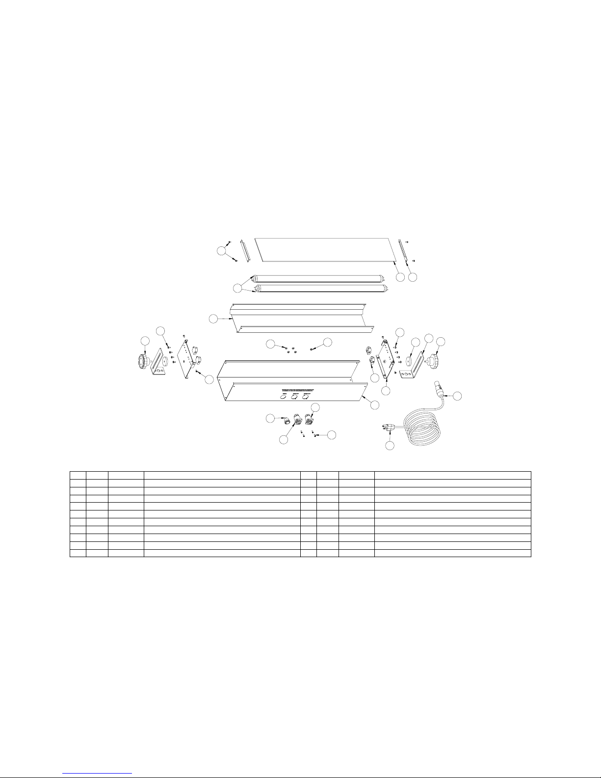
Exploded View & Part List EM-22L
#
QTY.
PART # PART NAME
1 1
104-064-03
Housing, Effects Master 2'
2 2
104-059-03
Cover, Housing, Side
3 12
121-005
Screw, M, PHL, PH, 6-32 x 1/4" 18-8 SS
4 1
126-004-03
Reflector, 2' Fluorescent
5 2
104-003-03
Bracket, Mounting
6 2
121-051-01
Washer, Neoprene, 1.5” OD, .25” ID .2” THK Black
7 2
120-002
Knob, Bracket Adjustment
8 1
107-003
Cord, Power, Black, 16 AWG, 6’
9 4
108-004
Socket, Lamp, G13 Base
10 8
121-017
Screw SM, PHL, PH, #8 x 3/8”, 18-8 SS
#
QTY.
PART # PART NAME
12
2
121-033
Kepnut, 4-40, 18-8 SS
13 4
121-003
Screw, M, PHL, PH, 4-40 x 3/8” 18-8 SS
14 2
104-004-01
Bracket, Lens Retaining (Optional Lens Kit)
15 1
124-015-01
Lens Clear UVT, 2’ x 4 3/4” (Optional Lens Kit
16 1
106-053 Receptacle, PowerCON 1 Power Out NAC3MPB-1
19 1
106-050
Connector, PowerCON 1, Power In NAC3FCA
11
4
142-001
Lamp, LED, SableLED, T9, BLB, 24”, 15W
17 1
106-051
Receptacle, PowerCON 1 Power-In NACMPA-1
18 1
105-020
Switch, DPST, 15A, Effects Master Series, RRA12C1121
20 1
121-035
Kepnut, 6-32 18-8 SS
4
151114
5
6
2
8
1
7
7
3
10
3
12
13
10
9
16
17
18
19
20
10
Page 11
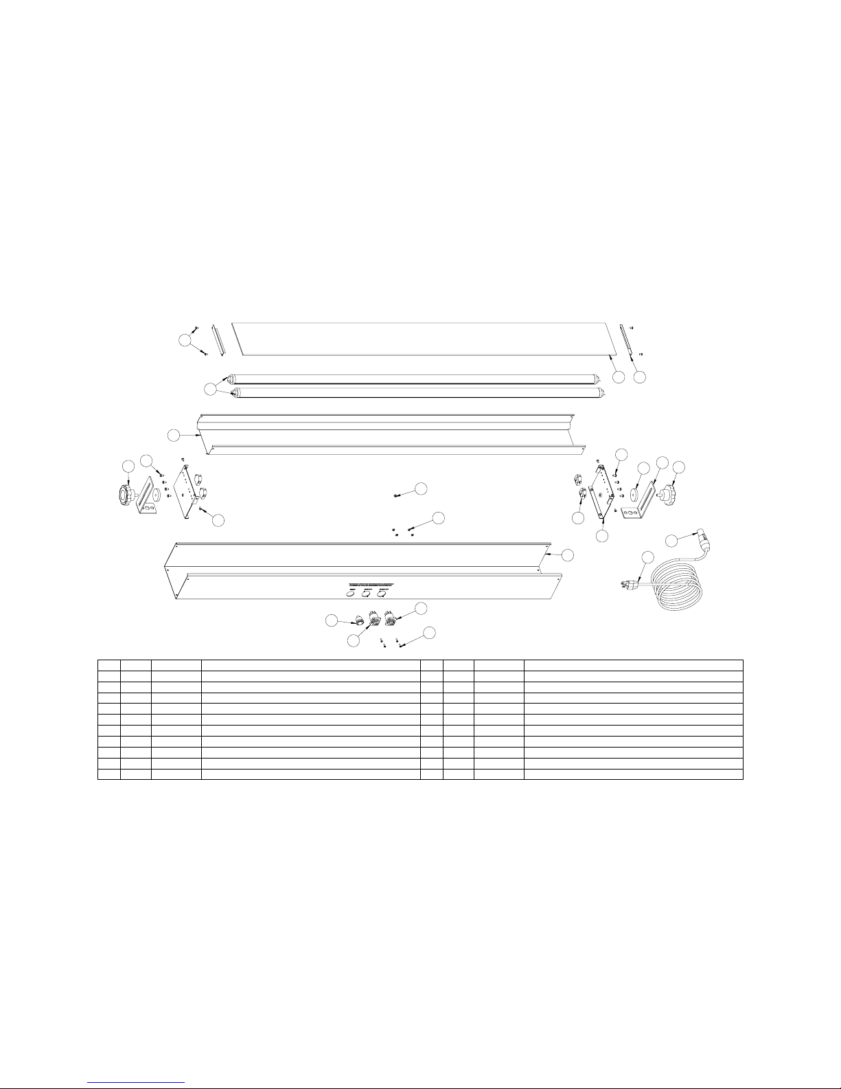
Exploded View & Part List EM-42L
11
#
QTY.
PART # PART NAME
1 1
104-065-07
Housing, 4'
2 2
104-059-03
Cover, Housing, Side
3 12
121-005
Screw, M, PHL, PH, 6-32 x 1/4" 18-8 SS
4 1
126-003-03
Reflector, 4' Fluorescent
5 2
104-003-02
Bracket, Mounting
6 2
121-051-01
Washer, Neoprene, 1.5” OD, .25” ID .2” THK Black
7 2
120-002
Knob, Bracket Adjustment
8 4
108-004
Socket Lamp G13 Base
9 8
121-017
Screw, SM, PHL, PH, #8 x 3/8”, 18-8SS
10 2
142-002
Lamp, LED, SableLED, T9, BLB, 48”, 30W
#
QTY.
PART # PART NAME
12
2
124-016-01
Lens, Clear, UVT, 4’ x 4 3/4” (Optional Lens Kit)
13 1
106-053
Receptacle, PowerCON 1, Power-OUT NAC3MPB-1
14 1
106-051
Receptacle, PowerCON 1, Power-IN NAC3MPA-1
15 1
105-020
Switch, DPST, 15A, Effects Master Series RRA12C1121
16 4
121-003 Screw, M, PHL, PH, 4-40 x 3/8” 18-8SS
19 4
121-033
Kepnut, 4-40 x 3/8” 18-8 SS
11
1
104-004-01
Bracket, Lens Retaining (Optional Lens Kit)
17 1
107-003
Cord, Power, Black, 16AWG, 6’
18 1
106-050
Connector, PowerCON 1, Power-In NAC3FCA
20 1
121-035
Kepnut, 6-32 18-8 SS
4
121011
5
6
2
17
1
7
7
3
9
3
9
8
16
15
14
13
18
20
19
Page 12
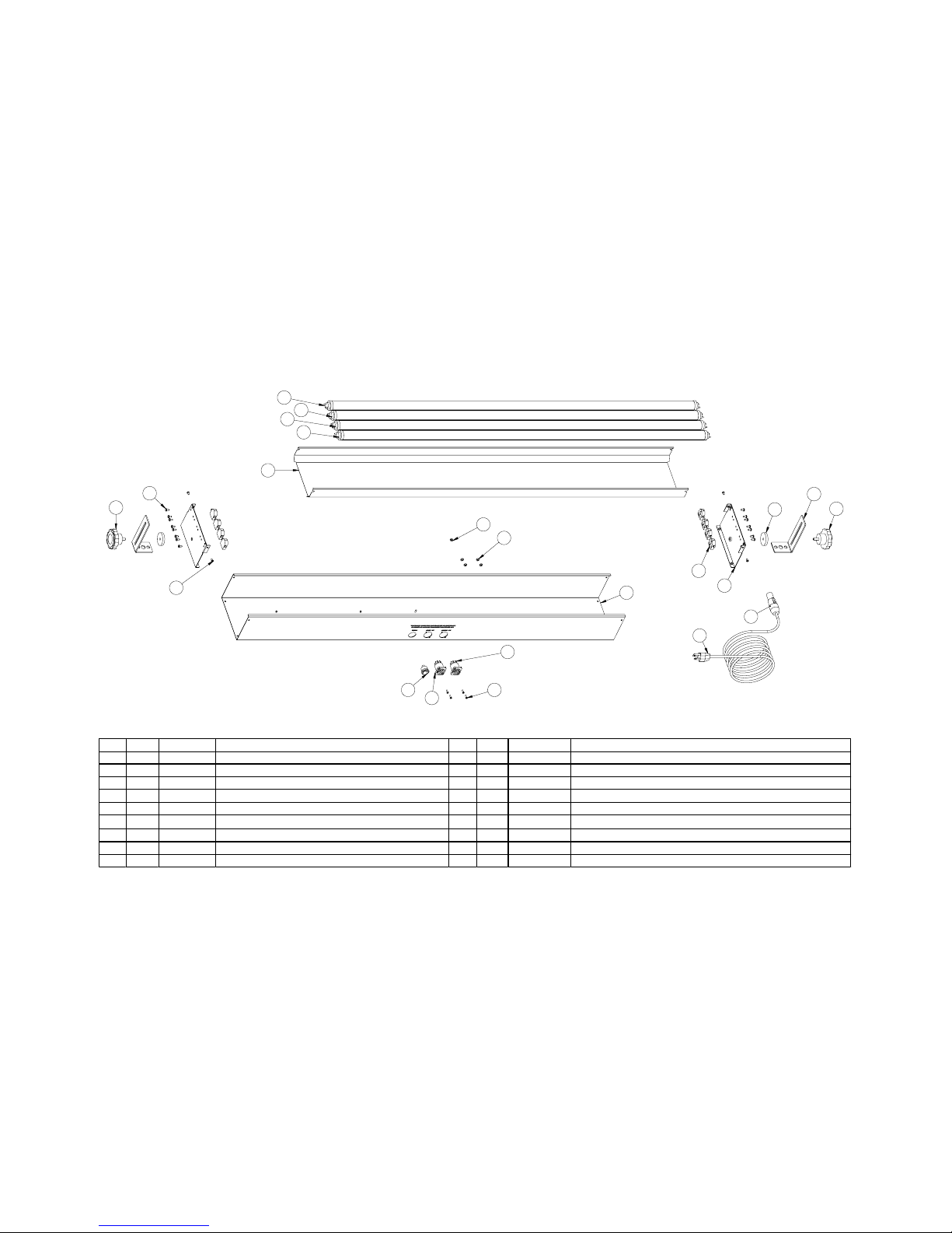
Exploded View & Part List EM-44L
12
PART NAME PART#QTY.# PART NAME
PART #QTY.#
104-066-0611
Housing Effects Master VHO
104-060-0322
Cover Housing Side VHO
121-00583
Screw, M, PHL, PH, 6-32 x 1/4” 18-8 SS
126-002-031
4
Reflector 4’ Fluorescent, VHO
104-003-0325 Bracket, Mounting
121-051-0126 Washer, Neoprene, 1.5”OD .25”ID .2” THK BK
120-00227 Knob, Bracket Adjustment
107-00318
Cord, Power, Black, 16 AWG, 6’
108-00489 Socket, Lamp G13 Base
121-0171610 Screw, SM, PHL, PH, #8 x 3/8”, 18-8 SS
141-002411
Lamp, LED, SableLED, T9, BLB, 48”, 30W
106-051112 Receptacle, PowerCON 1, Power-In NAC3MPA-1
106-053113 Receptacle, PowerCON 1, Power-Out NAC3MPB-1
105-020114 Switch, DSPT, 15A, Effects Master Series RRA12C1100
106-050115 Connector, PowerCON 1, Power-In NAC3FCA
121-003416 Screw, M, PHL, PH, 4-40 x 3/8” 18-8 SS
121-033417 Kepnut, 4-40, 18-8 SS
121-035118 Kepnut 6-32 18-8 SS
4
9
11
11
11
11
5
6
2
1
7
7
10
3
14
13
12
15
17
8
16
18
Page 13
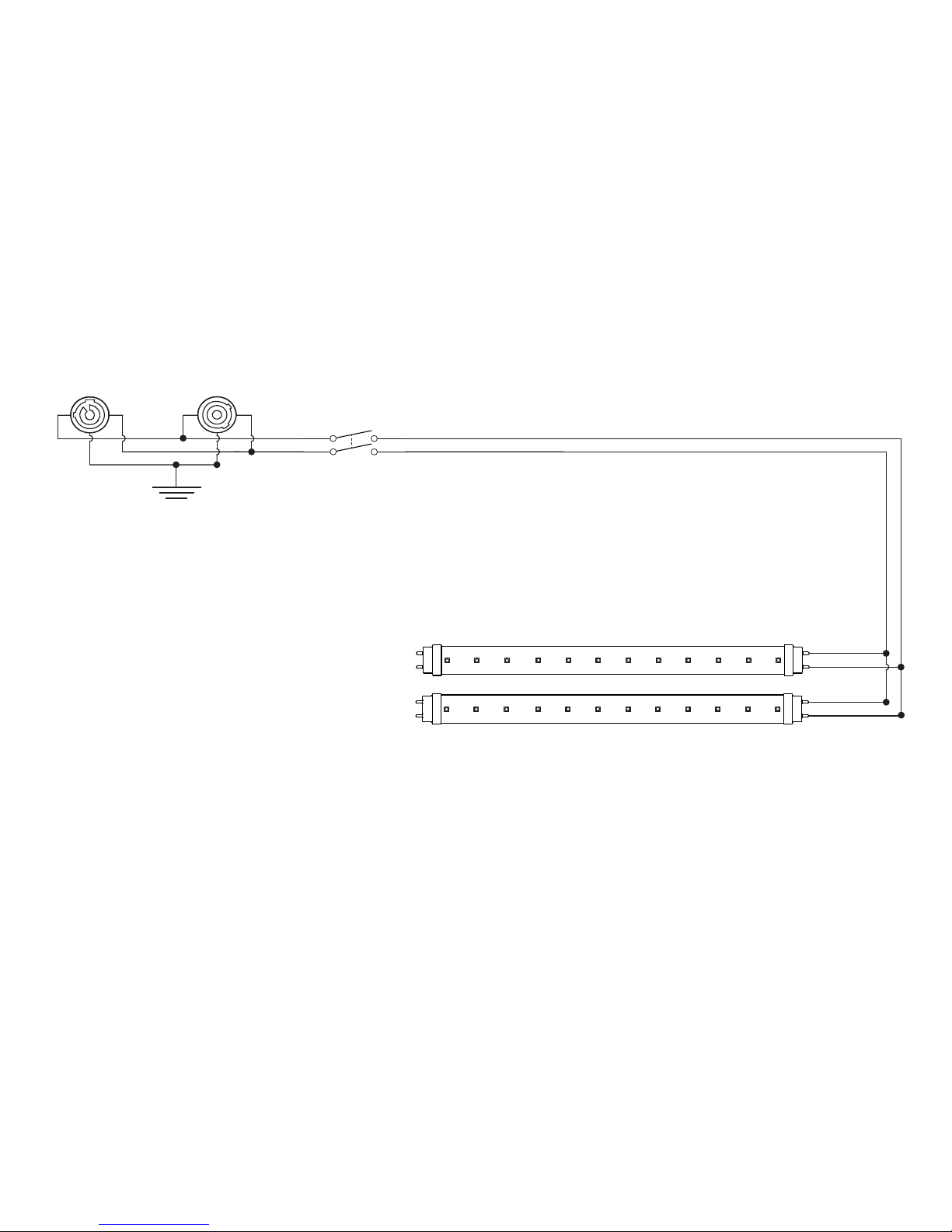
Schematic, LED Series EM-22L
13
BLACK
WHITE
POWER SWITCH
AC OUTPUT
AC INPUT
GREEN
Page 14
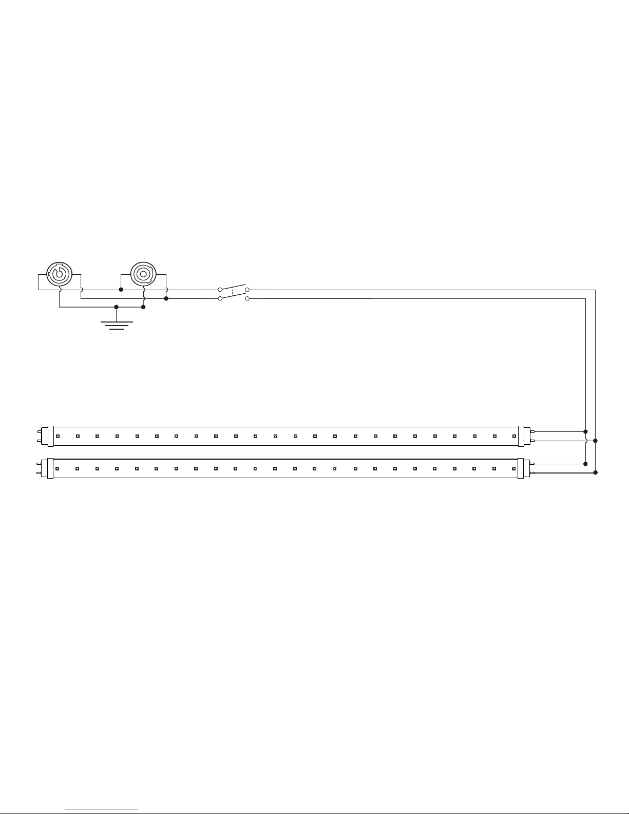
Schematic, LED Series EM-42L
14
BLACK
WHITE
POWER SWITCH
AC OUTPUT
AC INPUT
GREEN
Page 15
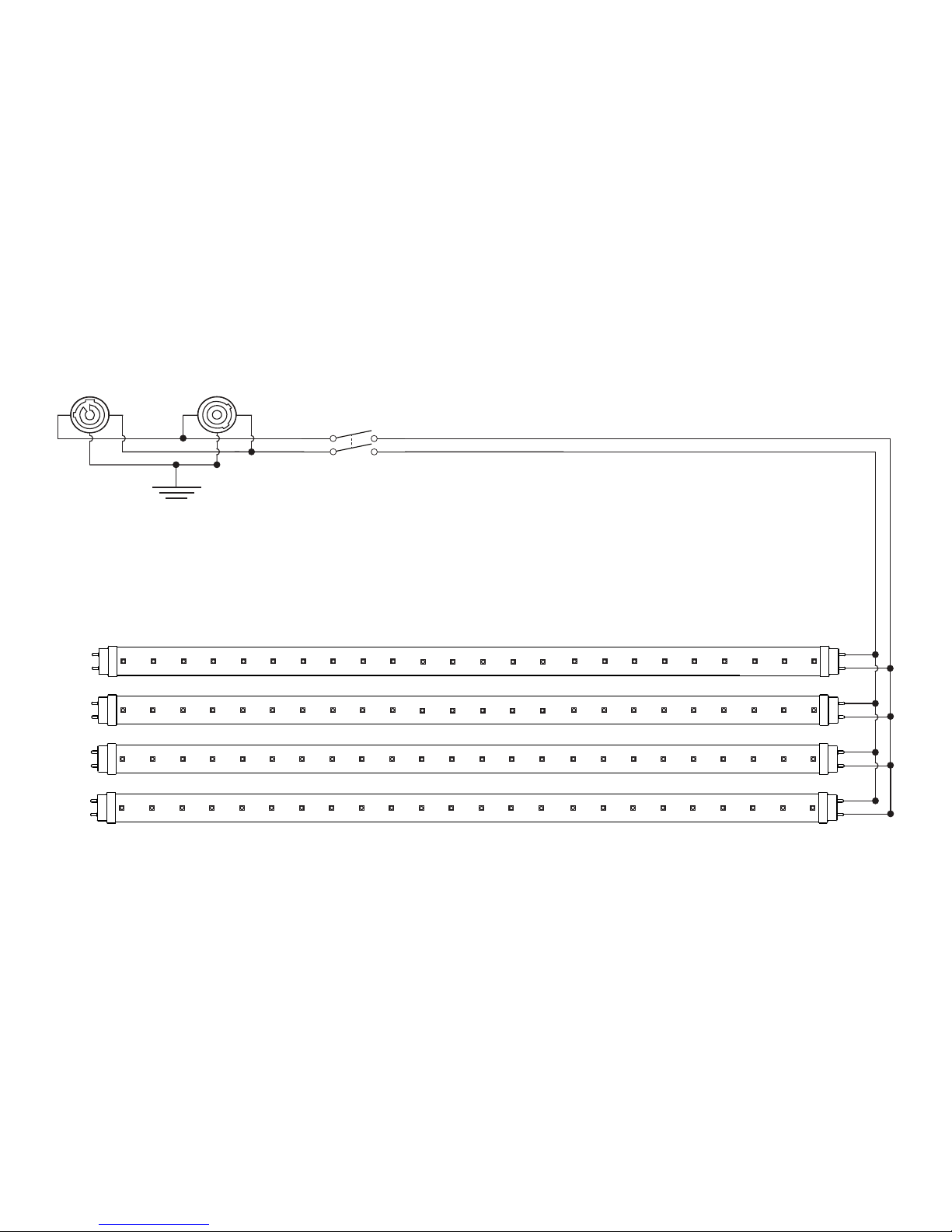
Schematic, LED Series EM-44L
15
BLACK
WHITE
POWER SWITCH
AC OUTPUT
AC INPUT
GREEN
Page 16
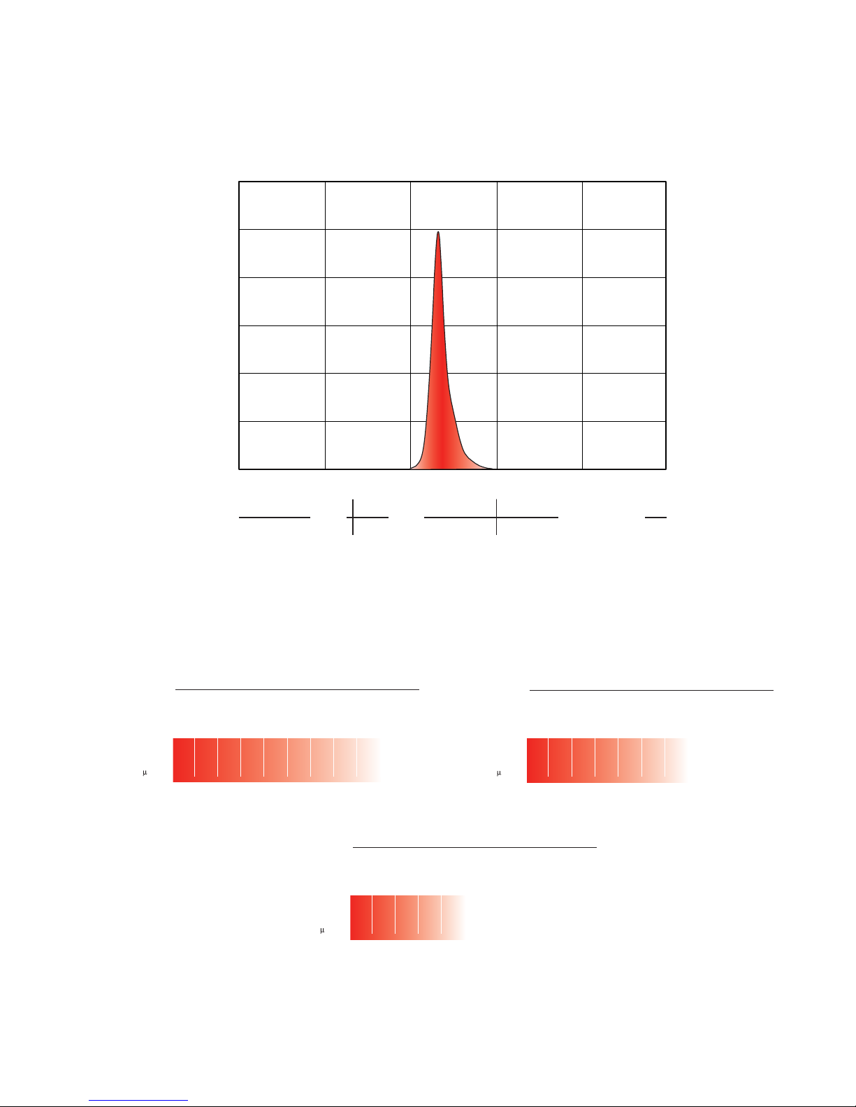
Spectral Output Graph
16
Photometrics Chart
0
20
40
60
80
100
250 300 350 400 450 500
UV-B UV-A
VISIBLE LIGHT
WAVELENGTH /NM
RELATIVE ENERGY (%)
All peak UV-A irradiance measurements taken at beam center using UVX Digital Radiometer and a calibrated 365nm sensor
Model EM-44L
Distance in Feet / Meters
17.3
5.2
270.0
34.6
10.5
67.5
69.3
21.1
16.8
103.9
31.6
7.5
138.6
42.2
4.2
173.2
52.7
2.7
207.8
63.3
1.8
242.5
73.9
1.3
277.1
24.3
1.0
Beam Diameter Feet
Beam Diameter Meters
Peak UV-A Irradiance
W/cm
2
5 / 1.52
10 / 3.05
20 / 6.10
30 / 9.14
40 / 12.19
50 / 15.24
60 / 18.29
70 / 21.33
80 / 24.38
Model EM-42L
Distance in Feet / Meters
17.3
5.2
130.0
34.6
10.5
32.2
69.3
21.1
8.1
103.3
31.6
3.6
138.6
42.2
2.0
173.2
52.7
1.3
207.8
63.3
.90
Beam Diameter Feet
Beam Diameter Meters
Peak UV-A Irradiance
W/cm
2
5 / 1.52
10 / 3.05
20 / 6.10
30 / 9.14
40 / 12.19
50 / 15.24
60 / 18.29
Model EM-22L
Distance in Feet / Meters
17.3
5.2
65.0
34.6
10.5
16.2
69.3
21.1
4.0
103.3
31.6
1.8
138.6
42.2
1.0
Beam Diameter Feet
Beam Diameter Meters
Peak UV-A Irradiance
W/cm
2
5 / 1.52
10 / 3.05
20 / 6.10
30 / 9.14
40 / 12.19
Page 17

Wildfire, Inc. Three Year Limited Warranty
Wildfire, Inc. warrants to the original owner or retail customer, that for a period of three years
from the date of delivery of any Wildfire Fixture; whether used in a portable or permanent
installation, such fixtures will be free from defects in material and workmanship under normal
use and conditions.
Warranty does not cover any product or part of a product that has been subjected to accident,
negligence, alteration, abuse or misuse and excludes any accessories or parts not supplied by
Wildfire. Warranty does not cover expendable parts such as fuses, lamps, glass or any
components warranted directly to the owner by the original manufacturer. This warranty does
not extend to products not manufactured by Wildfire.
Wildfire’s responsibility under this warranty shall be to repair or replace at Wildfire’s discretion
such parts as determined to be defective upon Wildfire’s inspection. Wildfire will not assume
any responsibility for any labor expended or materials used to repair any equipment without
Wildfire’s prior written authorization.
Wildfire, Inc. shall not be responsible for any incidental, general or consequential damages to
property, damage for loss of use, time profits or income, or any other charges.
The owners’ obligation during the warranty period is to notify Wildfire of any suspected defect,
to obtain a return authorization number, and to return the product freight and insurance
prepaid to the following address:
Wildfire Service, 2908 Oregon Court Suite G1, Torrance, CA 90503
(800) 937-8065 (310) 755-6780
Collect shipments for freight allowances or shipments without return authorization numbers
will not be accepted.
THIS WARRANTY IS EXPRESSLY IN LIEU OF ANY AND ALL OTHER WARRANTIES
EXPRESSED OR IMPLIED INCLUDING THE WARRANTIES OF MERCHANTABILITY AND
FITNESS FOR A PARTICULAR PURPOSE AND ALL OTHER OBLIGATIONS AND
LIABILITIES ON WILDFIRE’S PART. THERE ARE NO WARRANTIES WHICH EXTEND
BEYOND THE DESCRIPTION ON THE FACE HEREOF. THE OWNER ACKNOWLEDGES
THAT NO OTHER REPRESENTATIONS WERE MADE TO HIM WITH RESPECT TO THE
QUALITY AND FUNCTION OF THE GOODS SOLD.
This written warranty is intended as a complete and exclusive statement of the terms thereof.
Prior dealings or trade usage shall not be relevant to modify, explain or vary this warranty.
Acceptance of, or acquiescing in, a course of performance under this warranty shall not
modify the meaning of their agreement even though either party has knowledge of the
performance and a chance to object.
This limited warranty gives you specific legal rights and you may also have other rights which
vary from state to state. If any action or preceding results from this warranty, the prevailing
party will be entitled to all costs and attorney fees incurred in defending or prosecuting such
actions.
Page 18

2908 Oregon Ct. Suite G1, Torrance, CA 90503
P: 310.755.6780 800.937.8065 F: 310.755.6781
wildfirelighting.com [email protected]
2017 Wildfire, Inc.
c
215-011-03
 Loading...