

Wilderness Systems RUDDER KIT Supplemental Manual

RUDDER KIT - SUPPLEMENTAL
This kit contains the components and instructions needed to convert the Rudder Kit - Solo to multi-position, tandem (stern
seat) or solo (center seat) use in Pamlico tandems.
To complete rudder installation on a boat without rudder you will also need Rudder Kit - Solo #8070026.
This module will provide the parts needed to be able to move rudder foot pedal controls from stern seat position to center
seat and will interface with the rudder system installed via kit #8070026.
CAUTION: Considerable eort has been given to these instructions to provide for a successful installation of your new rudder
but the process does require permanent alteration of your kayak. Please read all instructions prior to beginning the process.
Be safe, measure twice before proceeding with any step requiring drilling or cutting of your hull. Use caution when tightening
screws in inserts molded in hull as they cannot be replaced. If you are uncomfortable with any part of this process, we suggest
you contact your local dealer for support and advice. It is possible they will undertake this installation for you at a moderate
cost. All directions included in these instructions reference starboard (right), port (left), forward, aft, behind, etc., are
given as if you are standing behind your kayak looking forward.
Call our Customer Service line: 800.445.3763 (and follow prompts for consumer assistance) should additional
assistance be required.
CONTENTS OF KIT
Part Number Description Qty
17010021 Footbrace Extrusion, Black, Aluminum 2
17010028 Keeper Footbrace with footpedals 2
15440025 Rudder Strap Assembly, 1” web 2
2RUD008 Rudder Strap Buckles 2
5175-3200 Shrink Tube, ¼” x 4” 1
3250-0100 Copper Swage 4
1FAS012 ¼ x 11/16” Aluminum Washers 2
59602000 Rubber Washers, black, ¼ x 5/8” 4
2FAS011 ¼-20 x ½” Phillips Truss Head Screws 2
2FAS012 ¼-20 x 5/8” Phillips Truss Head Screws 2
K4FAS007-1 #14 x ¾” Phillips Truss Head Screws 2
Additional Tools & Materials Required
Phillips head screwdriver
Cable cutters
Cable crimpers
Lighter or matches
INSTALLATION INSTRUCTIONS:
1. Remove existing stern and amidships Slidetrack footbraces – these braces will not be used and can be discarded.
2. Install aluminum Footbrace Extrusion Rails – Install the #17010021 extrusions at the center footbrace locations (see photo
below). Per the instructions for the #8070026 Course Control Rudder Kit, extrusions were previously installed at the stern
footbrace position.
Wilderness Systems, 575 Mauldin Road, Suite 200, Greenville, SC 29607 Rev. 09/15#59504259
3. Place the shorter screw, #2FAS011 #¼ - 20 x ½”, in the front hole and the longer screw, #2FAS012 #¼ - 20 x 5/8”, in the
rear hole. Reach inside the boat and slip a #59602000 #¼ x 5/8” rubber washer onto each screw between hull and
extrusion. Start the screws into the threaded holes of the extrusions with a hand screwdriver, being careful not to cross
thread. Tighten fully.
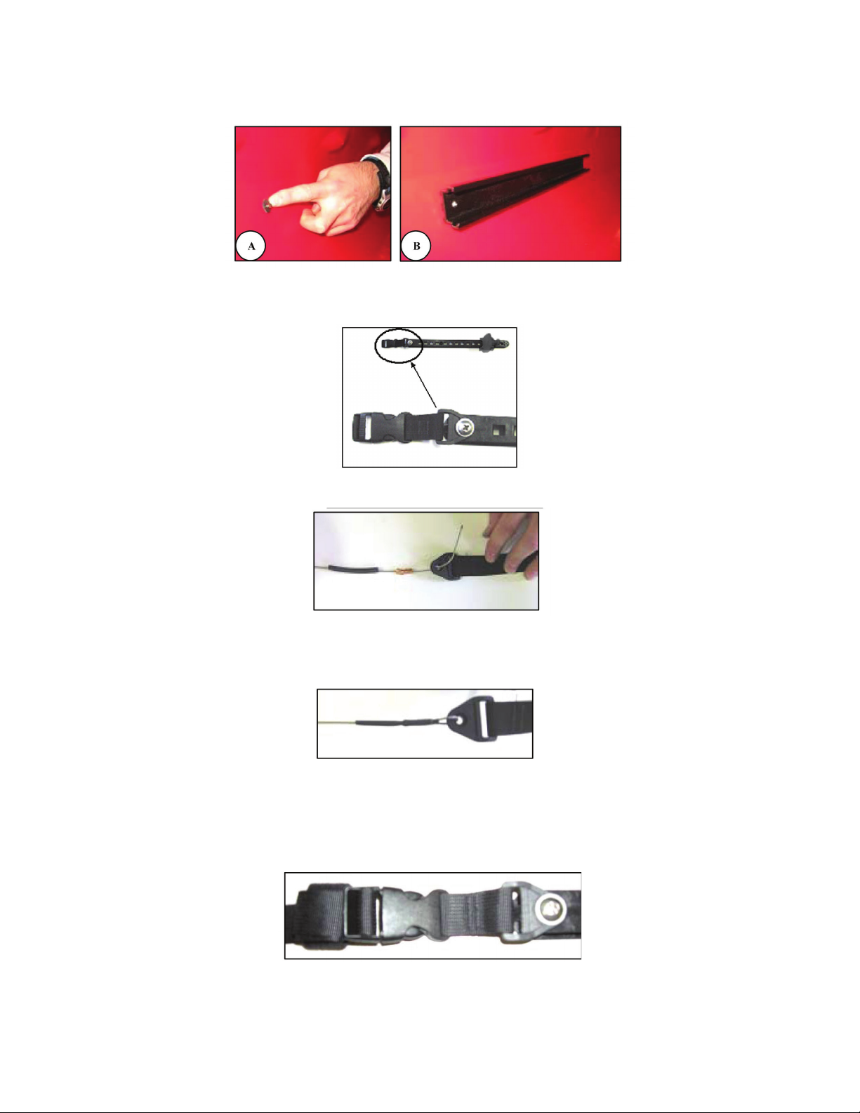
4. Attach the eyelet of the #2RUD008 Rudder Strap Buckle to the rear hole the #17010028 Keeper Footbrace using #
K4FAS007-1 #14 x ¾” Truss Head Screws and #1FAS0121/4 x 11/16 Aluminum Washers.
5. The cable enters the cable housing at the stern end of the boat and exits the housing into the cockpit area.
6. Place one section of shrink tubing # 5715-32001-1/4” Section of Shrink Tubing on the cable followed by 2 #3250-0100
cable swages. Thread the end of the cable through the eyelet of the rudder strap and then through the 2 cable swages
to form a loop.
7. Use the crimping tool to pinch the swages securely to the cable. Crimp both ends of each swage.
8. Slide the shrink tubing over the crimped swages and use lighter or matches to shrink the tubing tightly around the
swages.
9. Press the male connecter from the rudder strap into the rudder buckle and then slide the footbraces into the rear set of
extrusions. Roll up the excess rudder strap and secure it with the velcro tab.
10. If you are converting a ‘stern only’ rudder system additional swedges and shrink tubing are included for adjusting the
rudder cable length to attach to the strap.
#59504259
Wilderness Systems, 575 Mauldin Road, Suite 200, Greenville, SC 29607 Rev. 09/15
 Loading...