

Wilden T2 User Manual
T2
Original™ Series METAL Pumps
Simplify your process
EOM
Engineering
Operation &
Maintenance
REPLACES EOM-T2M 10/03
WIL-10200-E-03

TABLE OF CONTENTS
PAGE #
SECTION 1 — CAUTIONS ............................................................................................ 1
SECTION 2 — PUMP DESIGNATION SYSTEM......................................... 2
SECTION 3 — HOW IT WORKS (PUMP & AIR SYSTEMS) ............ 3
SECTION 4 — DIMENSIONAL DRAWINGS
A. T2 METAL & T2 UL METAL ............................................................................................... 4
B. T2 METAL SANIFLO
SECTION 5 — PERFORMANCE CURVES
A. T2 METAL Rubber-Fitted ................................................................................................... 6
B. T2 METAL TPE-Fitted ........................................................................................................ 6
C. T2 METAL PTFE-Fitted ...................................................................................................... 7
SECTION 6 — SUCTION LIFT CURVES & DATA .................................... 7
SECTION 7 — INSTALLATION AND OPERATION
A. Installation .......................................................................................................................... 8
B. Operation & Maintenance .................................................................................................. 9
C. Troubleshooting Pumps ..................................................................................................... 10
FDA
........................................................................................................ 5
SECTION 8 — DIRECTIONS FOR DISASSEMBLY/REASSEMBLY
A. T2 METAL – Disassembly, Cleaning, Inspection ............................................................... 11
B. Turbo-Flo™ Pump Air Valve/Center Section – Disassembly, Cleaning, Inspection ......... 13
C. Reassembly Hints & Tips ................................................................................................... 14
SECTION 9 — EXPLODED VIEW/PARTS LISTING
A. T2 METAL Rubber/TPE-Fitted ........................................................................................... 16
B. T2 METAL PTFE-Fitted ...................................................................................................... 18
SECTION 10 — ELASTOMER OPTIONS ......................................................... 20
O
z
I
I
&
I
s
s
a
l
C
NON
U.S. Clean Air Act
Amendments of 1990
D
USE
e
p
l
e
t
i
n
g
o
n
e
s
e
c
n
a
t
s
b
u
S
SECTION 1
WILDEN MODEL T2 METAL
CAUTIONS – READ FIRST!
TEMPERATURE LIMITS:
Polypropylene 0°C to 79°C 32°F to 175°F
Neoprene –17.8°C to 93.3°C 0°F to 200°F
Buna-N –12.2°C to 82.2°C 10°F to 180°F
EPDM –51.1°C to 137.8°C –60°F to 280°F
Viton® –40°C to 176.7°C –40°F to 350°F
Wil-Flex™ –40°C to 107.2°C –40°F to 225°F
Polyurethane –12.2°C to 65.6°C 10°F to 150°F
Saniflex™ –28.9°C to 104.4°C –20°F to 220°F
PTFE 4.4°C to 148.9°C 40°F to 300°F
CAUTION:
check the temperature limits for all wetted components.
Example: Viton® has a maximum limit of 176.7°C (350°F)
but polypropylene has a maximum limit of only 79°C
(175°F).
CAUTION: Maximum temperature limits are based
upon mechanical stress only. Certain chemicals will
significantly reduce maximum safe operating temperatures. Consult engineering guide for chemical compatibility and temperature limits.
CAUTION: Always wear safety glasses when operating pump. If diaphragm rupture occurs, material being
pumped may be forced out air exhaust.
WARNING: Prevention of static sparking — If static
sparking occurs, fire or explosion could result. Pump,
valves, and containers must be properly grounded when
handling flammable fluids and whenever discharge of
static electricity is a hazard.
CAUTION: Do not exceed 8.6 bar (125 psig) air supply
pressure. (3.4 bar [50 psig] for UL models.)
CAUTION: Before any maintenance or repair is
attempted, the compressed air line to the pump should
be disconnected and all air pressure allowed to bleed
from pump. Disconnect all intake, discharge and air
lines. Drain the pump by turning it upside down and
allowing any fluid to flow into a suitable container.
CAUTION: Blow out air line for 10 to 20 seconds
before attaching to pump to make sure all pipe line
debris is clear. Use an in-line air filter. A 5µ (micron) air
filter is recommended.
NOTE: Tighten clamp bands and retainers prior to
installation. Fittings may loosen during transportation.
When choosing pump materials, be sure to
NOTE: When installing PTFE diaphragms, it is important to tighten outer pistons simultaneously (turning in
opposite directions) to ensure tight fit.
NOTE: Before starting disassembly, mark a line from
each liquid chamber to its corresponding air chamber.
This line will assist in proper alignment during reassembly.
CAUTION: Verify the chemical compatibility of the
process and cleaning fluid to the pump’s component
materials in the Chemical Resistance Guide.
CAUTION: When removing the end cap using
compressed air, the air valve end cap may come out
with considerable force. Hand protection such as a
padded glove or rag should be used to capture the
end cap.
CAUTION: Only explosion proof (NEMA 7) solenoid
valves should be used in areas where explosion proof
equipment is required.
NOTE: All non lube-free air-operated pumps must
be lubricated. Wilden suggests an arctic 5 weight oil
(ISO grade 15). Do not over-lubricate pump. Over-lubrication will reduce pump performance.
NOTE:
psig)
CAUTION: Do not lubricate lube-free pumps.
CAUTION: CAUTION: For UL listed pumps, do not
exceed 3.4 bar (50 psig) air supply pressure.
CAUTION: For UL listed pumps, all pipe connections
are to be made using UL Classified gasoline-resistant
pipe compound.
CAUTION: For UL listed pumps, all installations must
conform with NFPA 30, NFPA 30A, and all other applicable codes.
CAUTION: For UL listed pumps, air exhaust port is to
be connected to pipe or tubing to be routed outdoors
or other location determined to be equivalent.
CAUTION: For UL listed pumps, pump is to be
grounded using the jam-nut located atop the long
vertical carriage bolt. The ground connection is marked
with a tag having the grounding symbol.
UL-listed pumps must not exceed 3.4 bar (50
air supply pressure.
Grounding Symbol
WIL-10200-E-03 WILDEN PUMP & ENGINEERING, LLC
1
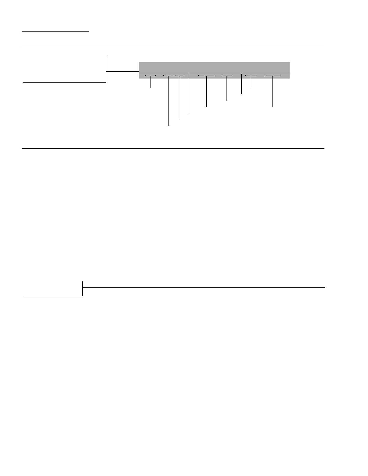
SECTION 2
WILDEN PUMP DESIGNATION SYSTEM
T2 ORIGINAL™
LEGEND
T2/XXXXX/XXX/XX/XXX/ XXXX
METAL
MODEL
DIAPHRAGMS
AIR VALVE
CENTER SECTION
WETTED PARTS & OUTER PIS TON
MODEL T2 METAL MATERIAL CODES
WETTED PARTS & OUTER PISTON
AA = ALUMINUM / ALUMINUM
AZ = ALUMINUM / NO PISTON
SS = STAINLESS STEEL /
STAINLESS STEEL
SZ = STAINLESS STEEL /
NO PISTON
CENTER SECTION
AA = ALUMINUM
CC = PFA COATED ALUMINUM
NN = NICKEL PLATED ALUMINUM
PP = POLYPROPYLENE
AIR VALVE
B = BRASS
C = PTFE PFA COATED
N = NICKEL PLATED
* = NO AIR VALVE
DIAPHRAGMS
BNS = BUNA-N (Red Dot)
EPS = EPDM (Blue Dot)
FSS = SANIFLEX™
[Hytrel® (Cream)]
LEL = PTFE-EPDM BACKED, IPD
NES = NEOPRENE (Green Dot)
PUS = POLYURETHANE (Clear)
TEU = PTFE W/EPDM
BACK-UP (White)
TNU = PTFE W/NEOPRENE
BACK-UP (White)
TSU = PTFE W/SANIFLEX™
BACK-UP (White)
VTS = VITON® (White Dot)
WFS = WIL-FLEX™ [Santoprene
(Orange Dot)]
XBS = CONDUCTIVE BUNA-N
(Two Red Dots)
VALVE BALL
BN = BUNA-N (Red Dot)
EP = EPDM (Blue Dot)
FS = SANIFLEX™
[Hytrel®(Cream)]
FV = SANITARY VITON
(Two White Dots)
NE = NEOPRENE (Green Dot)
PU = POLYURETHANE (Brown)
TF = PTFE (White)
VT = VITON® (White Dot)
WF = WIL-FLEX™ [Santoprene
(Orange Dot)]
VALVE SEAT
A = ALUMINUM
®
S = STAINLESS STEEL
®
VALVE SEAT
VALVE BALLS
®
O-RINGS
VALVE SEAT O-RING
BN = BUNA-N
EP = EPDM
FS = SANIFLEX™
[Hytrel®(Cream)]
PU = POLYURETHANE (Brown)
TF = PTFE (White)
WF = WIL-FLEX™ [Santoprene®]
SPECIALTY
CODE
(if applicable)
SPECIALTY CODES
0002 Unpainted, special instructions
0014 BSPT
0017 BSPT, unpainted, special instructions
0023 Wing nuts
0070 Saniflo™ FDA
0079 Tri-clamp fittings, wing nuts
0080 Tri-clamp fittings ONLY
0090 UL listed
0091 UL listed, Wil-Gard II™ 110V
0100 Wil-Gard II™ 110V
0102 Wil-Gard II™ sensor wires ONLY
0103 Wil-Gard II™ 220V
0104 Wil-Gard II™ 110V, spark free
0105 Spark free, Wil-Gard II™ 220V
0108 BSPT, Wil-Gard II™ 220V
0120 Saniflo™ FDA, Wil-Gard II™ 110V
0206 PFA coated hardware,
Wil-Gard II™ sensor wires ONLY
0247 Discharge and inlet facing exhaust, special
instructions
0249 Discharge facing forward, spark free,
BSPT, special instructions
0250 Discharge facing forward, special
instructions
0251 Discharge facing forward, BSPT,
special instructions
0300 Without air valve
0315 PFA coated hardware, BSPT
0330 Wing nuts, BSPT
0502 PFA coated hardware
0603 PFA coated hardware, Wil-Gard II™ 110V
0608 PFA coated hardware, Wil-Gard II™ 220V
*O-RINGS NOT REQUIRED.
NOTE: MOST ELASTOMERIC MATERIALS USE COLORED DOTS FOR IDENTIFICATION.
Viton is a registered trademark of DuPont Dow Elastomers.
WILDEN PUMP & ENGINEERING, LLC WIL-10200-E-03
2
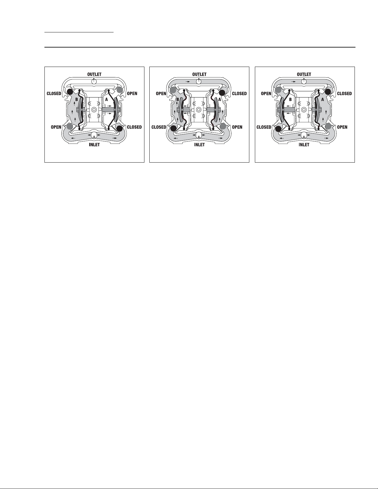
SECTION 3
THE WILDEN PUMP — HOW IT WORKS
The Wilden diaphragm pump is an air-operated, positive displacement, self-priming pump. These drawings show the flow
pattern through the pump upon its initial stroke. It is assumed the pump has no fluid in it prior to its initial stroke.
RIGHT STROKE MID STROKE LEFT STROKE
FIGURE 1 The air valve directs pressurized air to the back side of diaphragm
A. The compressed air is applied directly
to the liquid column separated by
elastomeric diaphragms. The diaphragm
acts as a separation membrane between
the compressed air and liquid, balancing
the load and removing mechanical
from the diaphragm. The compressed
moves the diaphragm away from the
center block of the pump. The opposite diaphragm is pulled in by the shaft
connected to the pressurized diaphragm.
Diaphragm B is on its suction stroke; air
behind the diaphragm has been forced
out to the atmosphere through the
exhaust port of the pump. The movement of diaphragm B toward the center
block of the pump creates a vacuum
within chamber B. Atmospheric pressure forces fluid into the inlet manifold
forcing the inlet valve ball off its seat.
Liquid is free to move past the inlet
valve ball and fill the liquid chamber (see
shaded area).
stress
air
FIGURE 2 When the pressurized
diaphragm, diaphragm A, reaches the
limit of its discharge stroke, the air valve
redirects pressurized air to the back
side of diaphragm B. The pressurized
air forces diaphragm B away from the
center block while pulling diaphragm A
to the center block. Diaphragm B is now
on its discharge stroke. Diaphragm B
forces the inlet valve ball onto its seat
due to the hydraulic forces developed in
the liquid chamber and manifold of the
pump. These same hydraulic forces lift
the discharge valve ball off its seat, while
the opposite discharge valve ball is forced
onto its seat, forcing fluid to flow through
the pump discharge. The movement of
diaphragm A toward the center block of
the pump creates a vacuum within liquid
chamber A. Atmospheric pressure forces
fluid into the inlet manifold of the pump.
The inlet valve ball is forced off its seat
allowing the fluid being pumped to fill the
liquid chamber.
FIGURE 3 At completion of the stroke,
the air valve again redirects air to the
back side of diaphragm A, which starts
diaphragm B on its exhaust stroke. As
the pump reaches its original starting
point, each diaphragm has gone through
one exhaust and one discharge stroke.
This constitutes one complete pumping
cycle. The pump may take several cycles
to completely prime depending on the
conditions of the application.
WIL-10200-E-03 WILDEN PUMP & ENGINEERING, LLC
3
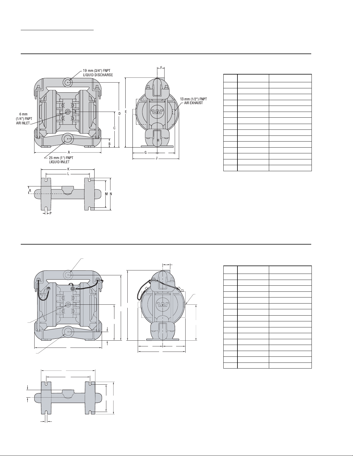
SECTION 4A
DIMENSIONAL DRAWING
T2 METAL
DIMENSIONS
ITEM METRIC (mm) STANDARD (inch)
A 267 10.5
B 36 1.4
C 137 5.4
D 254 10.0
E 279 11.0
F 28 1.1
G 97 3.8
H 76 3.0
J 185 7.3
K 211 8.3
L 173 6.8
M 107 4.2
N 127 5.0
P 8 0.3
R 33 1.3
BSPT Threads available
T2 METAL - UL LISTED
19 mm (3/4")
BSPT (FNPT) LIQUID DISCHARGE
6 mm (1/4")
FNPT
AIR INLET
A
25 mm (1")
BSPT (FNPT) LIQUID INLET
L
M
R
F
13 mm (1/2")
FNPT
E
D
C
B
G
N
P
H
K
AIR EXHAUST
J
DIMENSIONS
ITEM METRIC (mm) STANDARD (inch)
A 267 10.5
B 36 1.4
C 137 5.4
D 254 10.0
E 279 11.0
F 28 1.1
G 97 3.8
H 89 3.5
J 137 5.4
K 198 7.8
L 211 8.3
M 173 6.8
N 107 4.2
P 127 5.0
R 33 1.3
S 8 0.3
S
WILDEN PUMP & ENGINEERING, LLC WIL-10200-E-03
4
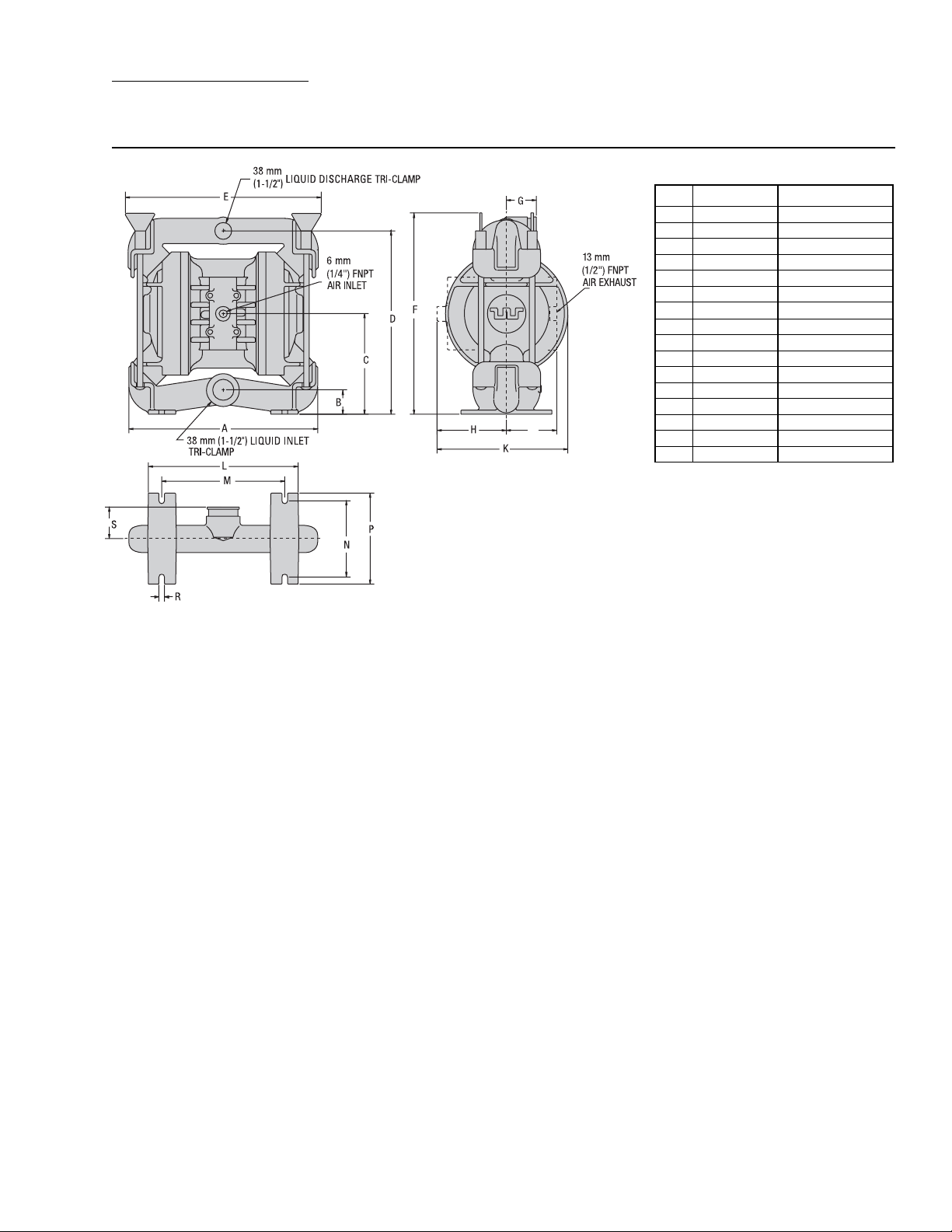
SECTION 4B
DIMENSIONAL DRAWING
T2 METAL SANIFLO
FDA
DIMENSIONS
ITEM METRIC (mm) STANDARD (inch)
A 264 10.4
B 36 1.4
C 137 5.4
D 257 10.1
E 267 10.5
F 295 11.6
G 41 1.6
H 97 3.8
J 74 2.9
K 183 7.2
L 211 8.3
M 173 6.8
N 107 4.2
P 127 5.0
R 8 0.3
S 43 1.7
WIL-10200-E-03 WILDEN PUMP & ENGINEERING, LLC
5
 Loading...