

Page 1
T15
Original™ Series METAL Pumps
Simplify your process
Engineering
Operation &
Maintenance
WIL-10252-E-01
Page 2
TABLE OF CONTENTS
SECTION 1 CAUTIONS—READ FIRST! . . . . . . . . . . . . . . . . . . . . . . . . . . . . . . . . . . . . . . . . . . . . . .1
SECTION 2 WILDEN PUMP DESIGNATION SYSTEM . . . . . . . . . . . . . . . . . . . . . . . . . . . . . . . . .2
SECTION 3 HOW IT WORKS—PUMP & AIR DISTRIBUTION SYSTEM . . . . . . . . . . . . . . . . 3
SECTION 4 DIMENSIONAL DRAWINGS . . . . . . . . . . . . . . . . . . . . . . . . . . . . . . . . . . . . . . . . . . . . .4
SECTION 5 PERFORMANCE
A. T15 Metal - Rubber-Fitted . . . . . . . . . . . . . . . . . . . . . . . . . . . . . . . . . . . . . . . . . . . . . . . .5
T15 Metal - TPE-Fitted . . . . . . . . . . . . . . . . . . . . . . . . . . . . . . . . . . . . . . . . . . . . . . . . . . .5
T15 Metal - PTFE-Fitted . . . . . . . . . . . . . . . . . . . . . . . . . . . . . . . . . . . . . . . . . . . . . . . . . .6
B. Suction Lift Curves . . . . . . . . . . . . . . . . . . . . . . . . . . . . . . . . . . . . . . . . . . . . . . . . . . . . .7
SECTION 6 SUGGESTED INSTALLATION, OPERATION & TROUBLESHOOTING . . . . . . . . 8
SECTION 7 ASSEMBLY / DISASSEMBLY . . . . . . . . . . . . . . . . . . . . . . . . . . . . . . . . . . . . . . . . . . . 11
Air Valve/Center Block Disassembly . . . . . . . . . . . . . . . . . . . . . . . . . . . . . . . . . . . . . . . . . 14
Reassembly Hints & Tips . . . . . . . . . . . . . . . . . . . . . . . . . . . . . . . . . . . . . . . . . . . . . . . . . .16
Gasket Kit Installation. . . . . . . . . . . . . . . . . . . . . . . . . . . . . . . . . . . . . . . . . . . . . . . . . . . . .17
SECTION 8 EXPLODED VIEW & PARTS LISTING
T15 Metal
Rubber/TPE-Fitted . . . . . . . . . . . . . . . . . . . . . . . . . . . . . . . . . . . . . . . . . . . . . . . . . . . 18
PTFE-Fitted . . . . . . . . . . . . . . . . . . . . . . . . . . . . . . . . . . . . . . . . . . . . . . . . . . . . . . . . . 22
SECTION 9 ELASTOMER OPTIONS . . . . . . . . . . . . . . . . . . . . . . . . . . . . . . . . . . . . . . . . . . . . . . . . .24
Page 3
Section 1
CAUTIONS—READ FIRST!
TEMPERATURE LIMITS:
Neoprene –17.8°C to 93.3°C 0°F to 200°F
Buna-N –12.2°C to 82.2°C 10°F to 180°F
EPDM –51.1°C to 137.8°C –60°F to 280°F
Viton
®
–40°C to 176.7°C –40°F to 350°F
Wil-Flex™ –40°C to 107.2°C –40°F to 225°F
Polyurethane 12.2°C to 65.6°C 10°F to 150°F
Saniflex™ –28.9°C to 104.4°C –20°F to 220°F
PTFE 4.4°C to 104.4°C 40° F to 220°F
Fluoro-Seal™ –40°C to 232°C –40°F to 450°F
CAUTION: When choosing pump materials, be sure
to check the temperature limits for all wetted components. Example: Viton
®
has a maximum limit of 176.7°C
(350°F) but polypropylene has a maximum limit of only
79°C (175°F).
CAUTION: Maximum temperature limits are based
upon mechanical stress only. Certain chemicals will
significantly reduce maximum safe operating temperatures. Consult engineering guide for chemical compatibility and temperature limits.
CAUTION: Always wear safety glasses when operating pump. If diaphragm rupture occurs, material being
pumped may be forced out air exhaust.
WARNING: Prevention of static sparking — If static
sparking occurs, fire or explosion could result. Pump,
valves, and containers must be properly grounded when
handling flammable fluids and whenever discharge of
static electricity is a hazard.
CAUTION: Do not exceed 8.6 bar (125 psig) air supply
pressure. (3.4 bar [50 psig] on UL models.)
CAUTION: Before any maintenance or repair is
attempted, the compressed air line to the pump should
be disconnected and all air pressure allowed to bleed
from pump. Disconnect all intake, discharge and air
lines. Drain the pump by turning it upside down and
allowing any fluid to flow into a suitable container.
CAUTION: Blow out air line for 10 to 20 seconds
before attaching to pump to make sure all pipe line
debris is clear. Use an in-line air filter. A 5μ (micron) air
filter is recommended.
NOTE: When installing PTFE diaphragms, it is important to tighten outer pistons simultaneously (turning in
opposite directions) to ensure tight fit.
WARNING: Tighten all clamp bands and retainers prior
to installation. Fittings may loosen during transportation.
NOTE: Before starting disassembly, mark a line from
each liquid chamber to its corresponding air chamber.
This line will assist in proper alignment during reassembly.
CAUTION: Verify the chemical compatibility of the
process and cleaning fluid to the pump's component
materials in the Chemical Resistance Guide (see E4).
CAUTION: When removing the end cap using
compressed air, the air valve end cap may come out
with considerable force. Hand protection such as a
padded glove or rag should be used to capture the
end cap.
NOTE: All non lube-free air-operated pumps must be
lubricated. Wilden suggests an arctic 5 weight oil (ISO
grade 15). Do not over-lubricate pump. Over-lubrication
will reduce pump performance.
NOTE: UL-listed pumps must not exceed 3.4 bar
(50 psig) air supply pressure.
CAUTION: Only explosion proof (NEMA 7) solenoid
valves should be used in areas where explosion proof
equipment is required.
CAUTION: Do not hang Stallion models by their
handles.
1
WILDEN PUMP & ENGINEERING, LLCWIL-10252-E-01
Page 4
Section 2
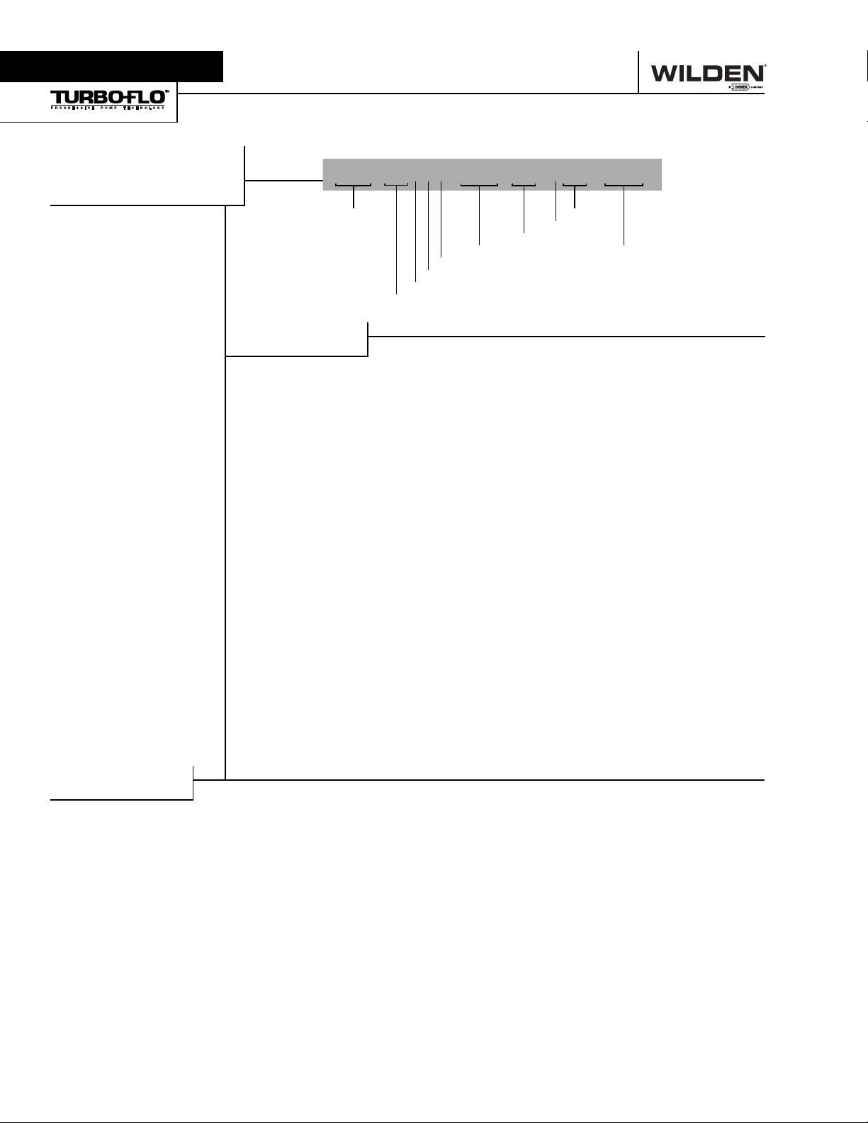
WILDEN PUMP DESIGNATION SYSTEM
T15 ORIGINAL™
METAL
76 mm (3") Pump
Maximum Flow Rate:
878 lpm (232 gpm)
LEGEND
T15 /XXXXX / XXX / XX / XXX / XXXX
MODEL
MATERIAL CODES
MODEL
T15 = 76 MM (3")
WETTED PARTS & OUTER PISTON
AA = ALUMINUM / ALUMINUM
WW = CAST IRON / CAST IRON
AIR CHAMBERS
A = ALUMINUM
CENTER BLOCK
A = ALUMINUM
P = POLYPROPYLENE
AIR VALVE
B = BRASS
DIAPHRAGMS
VALVE BALLS
AIR VALVE
CENTER BLOCK
AIR CHAMBERS
WETTED PARTS & OUTER PISTON
DIAPHRAGMS
XBS = CONDUCTIVE BUNA-N
(Two Red Dots)
BNS = BUNA-N (Red Dot)
FSS = SANIFLEX™
[Hytrel
®
(Cream)]
EPS = EPDM (Blue Dot)
NES = NEOPRENE (Green Dot)
PUS = POLYURETHANE (Clear)
TEU = PTFE W/EPDM
BACK-UP (White)
TNU = PTFE W/NEOPRENE
BACK-UP (White)
TSU = PTFE W/SANIFLEX™
BACK-UP (White)
BNU = BUNA-N, ULTRA-FLEX™
EPU = EPDM, ULTRA-FLEX™
NEU = NEOPRENE, ULTRA-FLEX™
VTU = VITON
VTS = VITON
®
, ULTRA-FLEX™
®
(White Dot)
WFS = WIL-FLEX™ [Santoprene
(Orange Dot)]
O-RINGS
VALVE SEAT
SPECIALTY
CODE
(if applicable)
VALVE BALL
BN = BUNA-N (Red Dot)
FS = SANvIFLEX™
[Hytrel
EP = EPDM (Blue Dot)
NE = NEOPRENE (Green Dot)
PU = POLYURETHANE (Brown)
TF = PTFE (White)
VT = VITON
WF = WIL-FLEX™ [Santoprene
(Orange Dot)]
VALVE SEAT
A = ALUMINUM
BN = BUNA-N (Red Dot)
FS = SANIFLEX™
[Hytrel
H = ALLOY C
M = MILD STEEL
EP = EPDM (Blue Dot)
®
NE = NEOPRENE (Green Dot)
PU = POLYURETHANE (Brown)
S = STAINLESS STEEL
VT = VITON
WF = WIL-FLEX™ [Santoprene
(Orange Dot)]
*Valve seat o-ring required.
VALVE SEAT O-RING
FS = FLUORO-SEAL™
TF = PTFE (White)
®
(Cream)]
®
(White Dot)
®
(Cream)]
®
(White Dot)
®
®
SPECIALTY CODES
0014 BSPT
0017 BSPT, unpainted
0030 Screen based
0036 Screen based, BSPT
0039 Screen based, polyurethane screen
0044 Stallion
0045 Stallion
0046 Stallion
0048 Stallion
0049 Stallion
0050 Stallion
®
, balls & seats ONLY
®
, shaft & bumpers ONLY
®
, internals, BSPT
®
, internals
®
, aluminum screen base
®
NOTE: MOST ELASTOMERIC MATERIALS USE COLORED DOTS FOR IDENTIFICATION.
Viton® is a registered trademarks of DuPont Dow Elastomers.
WILDEN PUMP & ENGINEERING, LLC WIL-10252-E-01
0051 Stallion®, BSPT
0053 Stallion
0054 Stallion
0112 Stallion
0113 Stallion
0115 Stallion®, footed, spark free, BSPT, without handles
0116 Stallion
0117 Stallion
0231 Stallion
0233 Stallion
®
, footed, BSPT
®
, footed
®
, footed, spark free, without handles
®
, internals, spark free, BSPT
®
, BSPT, without handles
®
, footed, BSPT, without handles
®
, externals (screen & handles)
®
, externals (screen & handles), BSPT
2
Page 5
Section 3
HOW IT WORKS—PUMP
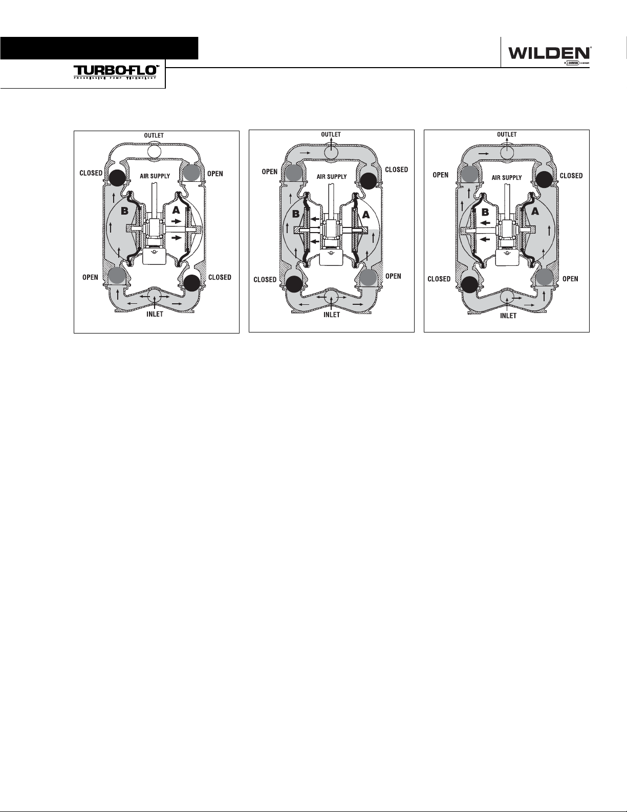
The Wilden diaphragm pump is an air-operated, positive displacement, self-priming pump. These drawings show the flow
pattern through the pump upon its initial stroke. It is assumed the pump has no fluid in it prior to its initial stroke.
RIGHT STROKE MID STROKE LEFT STROKE
FIGURE 1 The air valve directs pressurized air to the back side of diaphragm
A. The compressed air is applied directly
to the liquid column separated by elastomeric diaphragms. The diaphragm acts
as a separation membrane between the
compressed air and liquid, balancing the
load and removing mechanical stress
from the diaphragm. The compressed
air moves the diaphragm away from the
center block of the pump. The opposite diaphragm is pulled in by the shaft
connected to the pressurized diaphragm.
Diaphragm B is on its suction stroke;
air behind the diaphragm has been
forced out to the atmosphere through
the exhaust port of the pump. The movement of diaphragm B toward the center
block of the pump creates a vacuum
within chamber B. Atmospheric pressure
forces fluid into the inlet manifold forcing the inlet valve ball off its seat. Liquid
is free to move past the inlet valve ball
and fill the liquid chamber (see shaded
area).
FIGURE 2 When the pressurized
diaphragm, diaphragm A, reaches the
limit of its discharge stroke, the air valve
redirects pressurized air to the back
side of diaphragm B. The pressurized
air forces diaphragm B away from the
center block while pulling diaphragm A
to the center block. Diaphragm B is now
on its discharge stroke. Diaphragm B
forces the inlet valve ball onto its seat
due to the hydraulic forces developed
in the liquid chamber and manifold of
the pump. These same hydraulic forces
lift the discharge valve ball off its seat,
while the opposite discharge valve ball is
forced onto its seat, forcing fluid to flow
through the pump discharge. The movement of diaphragm A toward the center
block of the pump creates a vacuum
within liquid chamber A. Atmospheric
pressure forces fluid into the inlet manifold of the pump. The inlet valve ball is
forced off its seat allowing the fluid being
pumped to fill the liquid chamber.
FIGURE 3 At completion of the stroke,
the air valve again redirects air to the
back side of diaphragm A, which starts
diaphragm B on its exhaust stroke. As
the pump reaches its original starting
point, each diaphragm has gone through
one exhaust and one discharge stroke.
This constitutes one complete pumping
cycle. The pump may take several cycles
to completely prime depending on the
conditions of the application.
3
WILDEN PUMP & ENGINEERING, LLCWIL-10252-E-01
Page 6
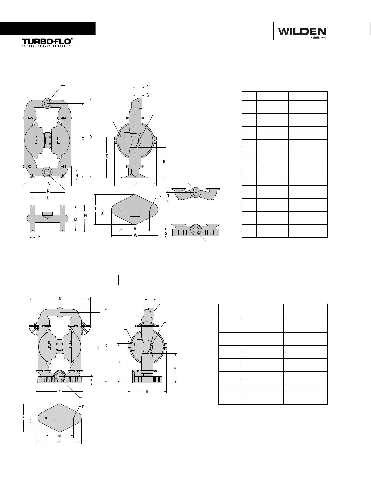
Section 4
T15 Metal
DIMENSIONAL DRAWINGS
76 mm (3") FNPT
76 mm
(3") FNPT - ALUM.
STAINLESS STEEL &
CAST IRON
ALUMINUM
19 mm
(3/4") FNPT
AIR INLET
ALUMINUM BASE SCREEN MODEL
25 mm (1") FNPT
EXHAUST
76 mm
(3") FNPT
FOOTED BASE FOR
STAINLESS STEEL MODELS
76 mm (3") FNPT - CAST IRON
76 mm
(3") MNPT
DIMENSIONS
ITEM METRIC (mm) STANDARD (inch)
A 505 19.9
B 58 2.3
C 762 30.0
D 823 32.4
E 419 16.5
F 71 2.8
G 69 2.7
H 312 12.3
J 427 16.8
K 361 14.2
L 305 12.0
M 259 10.2
N 282 11.1
P 15 0.6
R 71 2.8
S 66 2.6
T 305 12.0
U 43 1.7
V 305 12.0
W 478 18.8
X Ø15 Ø0.6
BSP threads available.
T15 Metal Stallion
76 mm (3") FNPT INLET
19 mm
(3/4") FNPT
AIR INLET
76 mm (3")
FNPT DISCHARGE
25 mm (1") FNPT EXHAUST
DIMENSIONS
ITEM METRIC (mm) STANDARD (inch)
A 505 19.9
B 71 2.8
C 775 30.5
D 836 32.9
E 737 29.0
F 69 2.7
G 325 12.8
H 427 16.8
J 432 17.0
K 310 12.2
L 43 1.7
M 305 12.0
N 480 18.9
P Ø15 Ø0.6
WILDEN PUMP & ENGINEERING, LLC WIL-10252-E-01
4
Page 7
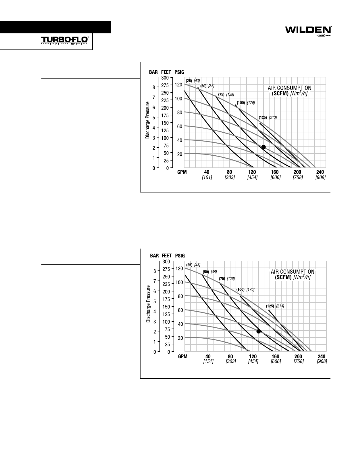
Section 5A
PERFORMANCE
T15 METAL
RUBBER-FITTED
Height ...................................... 810 mm (31.9")
Width ....................................... 432 mm (17.0")
Depth ...................................... 279 mm (11.0")
Est. Ship Weight ............
Air Inlet .........................................19 mm (3/4")
Inlet ................................................ 76 mm (3")
Outlet ............................................. 76 mm (3")
Suction Lift ................................5.5 m Dry (18')
Displacement/Stroke ............. 5.3 l (1.40 gal.)
Max. Flow Rate ................... 878 lpm (232 gpm)
Max. Size Solids .......................... 10 mm (3/8")
1
Displacement per stroke was calculated at 4.8 bar
(70 psig) air inlet pressure against a 2 bar (30 psig)
head pressure.
Example: To pump 530 lpm (140 gpm) against
a discharge pressure head of 2.1 bar (30 psig)
requires 4.1 bar (60 psig) and 136 Nm
scfm) air consumption. (See dot on chart.)
Caution: Do not exceed 8.6 bar (125 psig) air
supply pressure.
Aluminum 53 kg (116 lbs)
Cast Iron 91 kg (200 lbs)
316 Stainless Steel 79 kg (175 lbs)
9.45 m Wet (31')
3
/h (80
1
[LPM]
Water Discharge Flow Rates
Flow rates indicated on chart were determined by pumping water.
For optimum life and performance, pumps should be specified so that daily operation parameters
will fall in the center of the pump performance curve.
T15 METAL
TPE-FITTED
Height ..................................... 810 mm (31.9")
Width ...................................... 432 mm (17.0")
Depth ..................................... 279 mm (11.0")
Est. Ship Weight ...........
Air Inlet ....................................... 19 mm (3/4")
Inlet ............................................... 76 mm (3")
Outlet ............................................ 76 mm (3")
Suction Lift .............................3.49 m Dry (13')
Displacement/Stroke ............ 5.4 l (1.43 gal.)
Max. Flow Rate .................. 845 lpm (223 gpm)
Max. Size Solids ......................... 10 mm (3/8")
1
Displacement per stroke was calculated at 4.8 bar
(70 psig) air inlet pressure against a 2 bar (30 psig)
head pressure.
Example: To pump 492 lpm (130 gpm) against
a discharge pressure head of 2.1 bar (30 psig)
requires 4.1 bar (60 psig) and 119 Nm
scfm) air consumption. (See dot on chart.)
Caution: Do not exceed 8.6 bar (125 psig) air
supply pressure.
Aluminum 53 kg (116 lbs)
Cast Iron 91 kg (200 lbs)
316 Stainless Steel 79 kg (175 lbs)
8.53 m Wet (28')
3
/h (70
1
[LPM]
Water Discharge Flow Rates
Flow rates indicated on chart were determined by pumping water.
For optimum life and performance, pumps should be specified so that daily operation parameters
will fall in the center of the pump performance curve.
5
WILDEN PUMP & ENGINEERING, LLCWIL-10252-E-01
Page 8
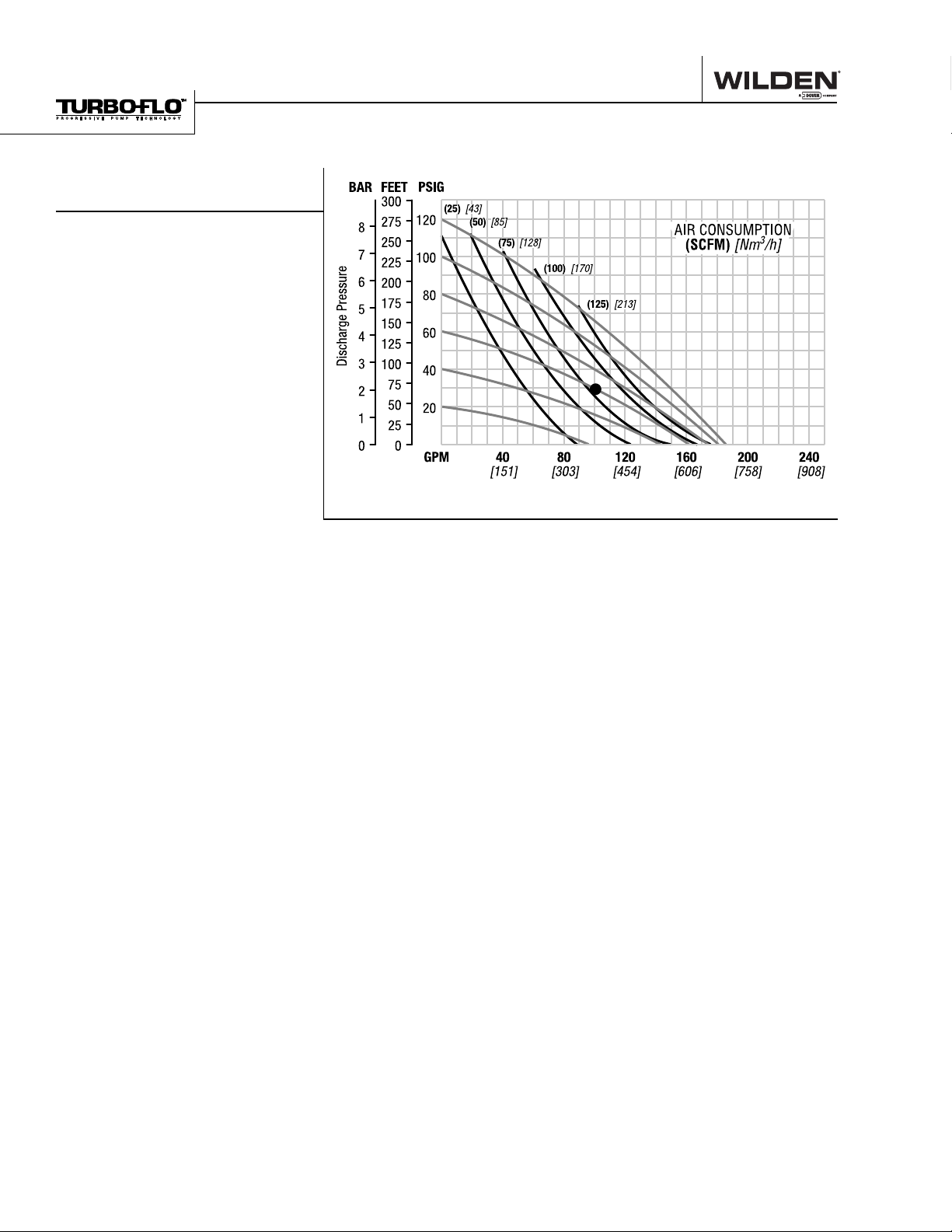
PERFORMANCE
T15 METAL
PTFE-FITTED
Height ..................................... 810 mm (31.9")
Width ...................................... 432 mm (17.0")
Depth ..................................... 279 mm (11.0")
Est. Ship Weight ...........
Air Inlet ....................................... 19 mm (3/4")
Inlet ............................................... 76 mm (3")
Outlet ............................................ 76 mm (3")
Suction Lift .............................3.49 m Dry (13')
Displacement/Stroke ............ 3.6 l (0.95 gal.)
Max. Flow Rate .................. 704 lpm (186 gpm)
Max. Size Solids ......................... 10 mm (3/8")
1
Displacement per stroke was calculated at 4.8 bar
(70 psig) air inlet pressure against a 2 bar (30 psig)
head pressure.
Example: To pump 378 lpm (100 gpm) against
a discharge pressure head of 2.1 bar (30 psig)
requires 4.1 bar (60 psig) and 136 Nm
scfm) air consumption. (See dot on chart.)
Caution: Do not exceed 8.6 bar (125 psig) air
supply pressure.
Aluminum 53 kg (116 lbs)
Cast Iron 91 kg (200 lbs)
316 Stainless Steel 79 kg (175 lbs)
8.53 m Wet (28')
3
/h (80
1
[LPM]
Water Discharge Flow Rates
Flow rates indicated on chart were determined by pumping water.
For optimum life and performance, pumps should be specified so that daily operation parameters
will fall in the center of the pump performance curve.
WILDEN PUMP & ENGINEERING, LLC WIL-10252-E-01
6
Page 9
Section 5B
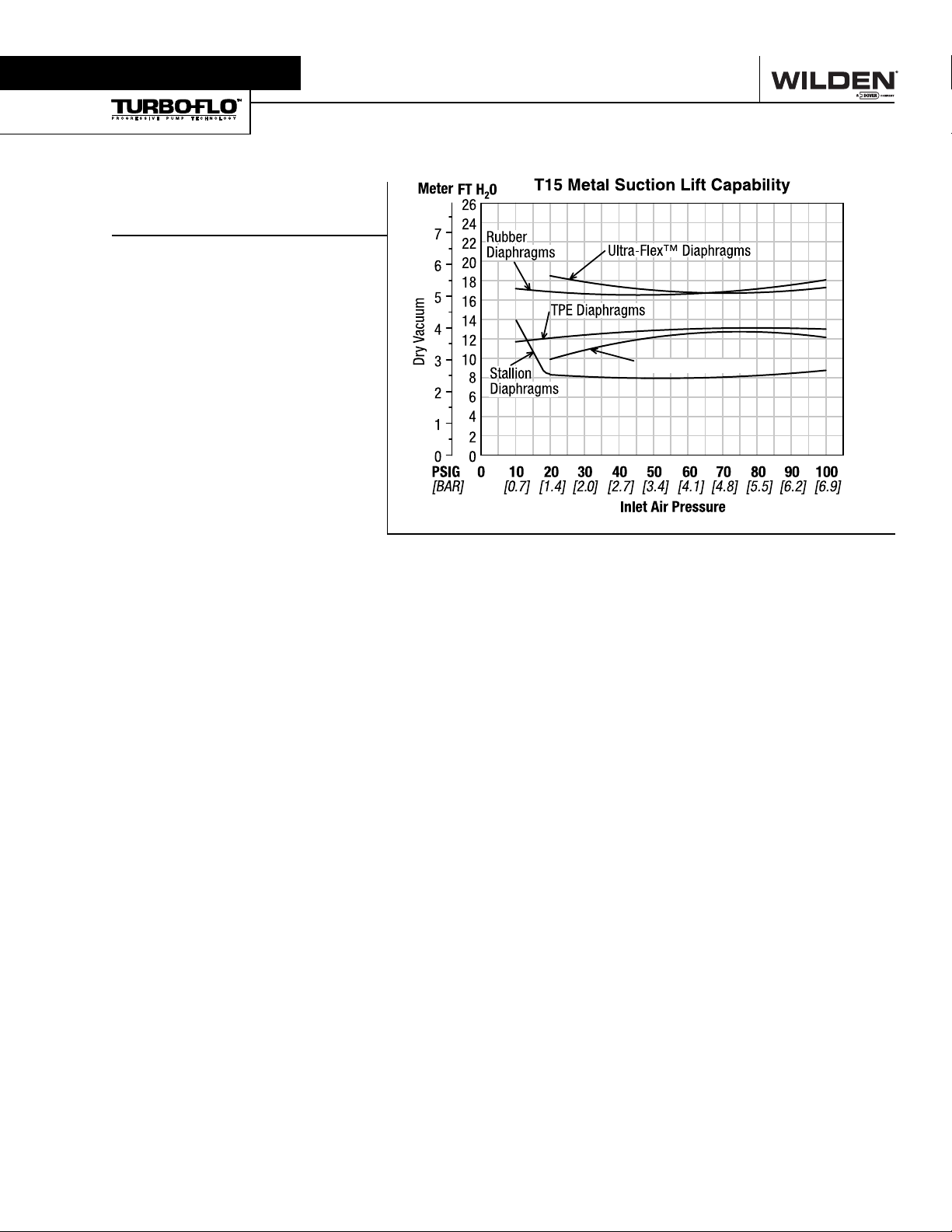
SUCTION LIFT CURVE
T15 METAL
SUCTION LIFT CAPABILITY
Suction lift curves are calibrated for
pumps operating at 305 m (1,000') above
sea level. This chart is meant to be a
guide only. There are many variables
which can affect your pump's operating
characteristics. The number of intake and
discharge elbows, viscosity of pumping
fluid, elevation (atmospheric pressure)
and pipe friction loss all affect the amount
of suction lift your pump will attain.
PTFE Diaphragms
7
WILDEN PUMP & ENGINEERING, LLCWIL-10252-E-01
Page 10

Section 6
SUGGESTED INSTALLATION
The Model T15 Metal pump has a 76 mm (3") inlet and 76 mm
(3") outlet and is designed for flows to 878 lpm (232 gpm). The
T15 Metal pump is manufactured with wetted parts of aluminum,
cast iron or 316 Stainless Steel. The center block of the T15
Metal is constructed of glass-filled polypropylene, aluminum,
nickel-plated aluminum, PTFE-coated aluminum or 316 Stainless Steel. A variety of diaphragms, valve balls, and o-rings are
available to satisfy temperature, chemical compatibility, abrasion
and flex concerns.
The suction pipe size should be at least 76 mm (3") diameter or
larger if highly viscous material is being pumped. The suction
hose must be non-collapsible, reinforced type as the T15 is
capable of pulling a high vacuum. Discharge piping should be at
least 76 mm (3"); larger diameter can be used to reduce friction
losses. It is critical that all fittings and connections are airtight or
a reduction or loss of pump suction capability will result.
INSTALLATION: Months of careful planning, study, and selection efforts can result in unsatisfactory pump performance if
installation details are left to chance.
Premature failure and long term dissatisfaction can be
avoided if reasonable care is exercised throughout the installation process.
LOCATION: Noise, safety, and other logistical factors usually
dictate that “utility" equipment be situated away from the
production floor. Multiple installations with conflicting requirements can result in congestion of utility areas, leaving few
choices for siting of additional pumps.
Within the framework of these and other existing conditions, every
pump should be located in such a way that five key factors are
balanced against each other to maximum advantage.
ACCESS: First of all, the location should be accessible. If it's
easy to reach the pump, maintenance personnel will have an
easier time carrying out routine inspections and adjustments.
Should major repairs become necessary, ease of access can
play a key role in speeding the repair process and reducing
total downtime.
AIR SUPPLY: Every pump location should have an air line
large enough to supply the volume of air necessary to achieve
the desired pumping rate (see Section 5). Use air pressure up
to a maximum of 8.6 bar (125 psig) depending upon pumping
requirements.
For best results, the pumps should use a 5 micron air filter,
needle valve and regulator. The use of an air filter before the
pump will insure that the majority of any pipeline contaminants will be eliminated.
SOLENOID OPERATION: When operation is controlled by
a solenoid valve in the air line, three-way valves should be
used, thus allowing trapped air to bleed off and improving
pump performance. Pumping volume can be set by counting
the number of strokes per minute and multiplying by displacement per stroke.
MUFFLER: Sound levels are reduced below OSHA specifications using the standard Wilden muffler element. Other
mufflers can be used to further reduce sound levels, but they
usually reduce pump performance.
ELEVATION: Selecting a site that is well within the pump's
dynamic lift capability will assure that loss-of-prime troubles will be eliminated. In addition, pump efficiency can be
adversely affected if proper attention is not given to elevation
(see Section 5).
WILDEN PUMP & ENGINEERING, LLC WIL-10252-E-01
PIPING: Final determination of the pump site should not be
made until the piping problems of each possible location have
been evaluated. The impact of current and future installations
should be considered ahead of time to make sure that inadvertent restrictions are not created for any remaining sites.
The best choice possible will be a site involving the shortest
and the straightest hook-up of suction and discharge piping.
Unnecessary elbows, bends, and fittings should be avoided.
Pipe sizes should be selected so as to keep friction losses
within practical limits. All piping should be supported independently of the pump. In addition, the piping should be aligned
so as to avoid placing stresses on the pump fittings.
Expansion joints can be installed to aid in absorbing the
forces created by the natural reciprocating action of the
pump. If the pump is to be bolted down to a solid foundation,
a mounting pad placed between the pump and foundation
will assist in minimizing pump vibration. Flexible connections
between the pump and rigid piping will also assist in minimizing pump vibration. If quick-closing valves are installed at any
point in the discharge system, or if pulsation within a system
becomes a problem, a surge suppressor should be installed
to protect the pump, piping and gauges from surges and
water hammer.
When pumps are installed in applications involving flooded
suction or suction head pressures, a gate valve should be
installed in the suction line to permit closing of the line for
pump service.
The T15 can be used in submersible applications only when
both wetted and non-wetted portions are compatible with
the material being pumped. If the pump is to be used in a
submersible application, a hose should be attached to the
pump's air exhaust and the exhaust air piped above the liquid
level.
If the pump is to be used in a self-priming application, be sure
that all connections are airtight and that suction lift is within
the pump's ability. Note: Materials of construction and elastomer material have an effect on suction lift parameters. Please
refer to Section 6.
Pumps in service with a positive suction head are most efficient when inlet pressure is limited to 0.5–0.7 bar (7–10 psig).
Premature diaphragm failure may occur if positive suction is
0.8 bar (11 psig) and higher.
THE MODEL T15 WILL PASS 10 mm (3/8") SOLIDS. THE
T15 STALLION WILL PASS 25 mm (1") SOLIDS. WHENEVER THE POSSIBILITY EXISTS THAT LARGER SOLID
OBJECTS MAY BE SUCKED INTO THE PUMP, A STRAINER
SHOULD BE USED ON THE SUCTION LINE.
CAUTION: DO NOT EXCEED 8.6 BAR (125 PSIG) AIR
SUPPLY PRESSURE. (3.4 BAR [50 PSIG] FOR UL
MODELS.)
PUMPS SHOULD BE THOROUGHLY FLUSHED WITH
WATER BEFORE INSTALLING INTO PROCESS LINES.
FDA AND USDA PUMPS SHOULD BE CLEANED AND/OR
SANITIZED BEFORE USE ON EDIBLE PRODUCTS.
BLOW OUT AIR LINE FOR 10 TO 20 SECONDS BEFORE
ATTACHING TO PUMP TO MAKE SURE ALL PIPE LINE
DEBRIS IS CLEAR. ALWAYS USE AN IN-LINE AIR
FILTER.
CAUTION: DO NOT HANG T15 STALLION PUMPS BY
THEIR HANDLES.
8
Page 11

SUGGESTED INSTALLATION
®
NOTE: In the event of a power failure, the shutoff valve should
be closed, if the restarting of the pump is not desirable once
power is regained.
AIR OPERATED PUMPS: To stop the pump from operating in
an emergency situation, simply close the “shut-off" valve (user
supplied) installed in the air supply line. A properly functioning
valve will stop the air supply to the pump, therefore stopping
output. This shut-off valve should be located far enough away
from the pumping equipment such that it can be reached safely
in an emergency situation.
SUGGESTED OPERATION & MAINTENANCE
OPERATION: Pump discharge rate can be controlled by limiting the volume and/or pressure of the air supply to the pump
(preferred method). An air regulator is used to regulate air
pressure. A needle valve is used to regulate volume. Pump
discharge rate can also be controlled by throttling the pump
discharge by partially closing a valve in the discharge line of
the pump. This action increases friction loss which reduces
flow rate. This is useful when the need exists to control the
pump from a remote location. When the pump discharge
pressure equals or exceeds the air supply pressure, the
pump will stop; no bypass or pressure relief valve is needed,
and pump damage will not occur. The pump has reached a
“deadhead" situation and can be restarted by reducing the
fluid discharge pressure or increasing the air inlet pressure. The Wilden T15 pump runs solely on compressed air
and does not generate heat, therefore your process fluid
temperature will not be affected.
RECORDS: When service is required, a record should be
made of all necessary repairs and replacements. Over a
period of time, such records can become a valuable tool
for predicting and preventing future maintenance problems
and unscheduled downtime. In addition, accurate records
make it possible to identify pumps that are poorly suited to
their applications.
MAINTENANCE AND INSPECTIONS: Since each application is unique, maintenance schedules may be different
for every pump. Frequency of use, line pressure, viscosity
and abrasiveness of process fluid all affect the parts life
of a Wilden pump. Periodic inspections have been found
to offer the best means for preventing unscheduled pump
downtime. Personnel familiar with the pump's construction
and service should be informed of any abnormalities that
are detected during operation.
9
WILDEN PUMP & ENGINEERING, LLCWIL-10252-E-01
Page 12

Section 5
TROUBLESHOOTING – AIR CONTROLLED
Pump will not run or runs slowly.
1. Check air inlet screen and air filter for debris.
2. Check for sticking air valve, flush air valve in solvent.
3. Check for worn out air valve. If piston face in air valve is
shiny instead of dull, air valve is probably worn beyond
working tolerances and must be replaced.
4. Check center block Glyd™ rings. If worn excessively,
they will not seal and air will simply flow through pump
and out air exhaust. Use only Wilden Glyd™ rings as
they are of special construction.
5. Check for rotating piston in air valve.
6. Check type of lubricant being used. A higher viscosity
oil than suggested may cause the piston to stick or run
erratically. Wilden suggests the use of an oil with arctic
characteristics (ISO 15-5 wt.).
Pump runs but little or no product flows.
1. Check for pump cavitation; slow pump speed down to
match thickness of material being pumped.
2. Check for sticking ball check valves. If material being
pumped is not compatible with pump elastomers, swelling may occur. Replace ball check valves and o-rings
with the proper elastomers.
3. Check to make sure all suction connections are air tight,
especially clamp bands around intake balls.
Pump air valve freezes.
Check for excessive moisture in compressed air. Either
install dryer or hot air generator for compressed air.
Air bubbles in pump discharge.
1. Check for ruptured diaphragm.
2. Check tightness of clamp bands, especially at intake
manifold.
Product comes out air exhaust.
1. Check for diaphragm rupture.
2. Check tightness of piston plates to shaft.
Pump rattles.
1. See E9 Troubleshooting Guide.
2. Create false discharge head or suction lift.
WILDEN PUMP & ENGINEERING, LLC WIL-10252-E-01
10
Page 13

Section 7
DISASSEMBLY/REASSEMBLY
CAUTION: Before any maintenance or repair is attempted,
the compressed air line to the pump should be disconnected
and all air pressure allowed to bleed from the pump. Disconnect all intake, discharge, and air lines. Drain the pump by
turning it upside down and allowing any fluid to flow into a
suitable container. Be aware of any hazardous effects of
contact with your process fluid.
The Wilden T15 has a 76 mm (3") inlet and 76 mm (3") outlet
and is designed for flows up to 878 lpm (232 gpm). The T15
is available in aluminum, cast iron or 316 stainless steel
wetted parts. The center block is available in polypropylene,
aluminum, nickel-plated aluminum, and 316 stainless steel.
Air valves come in brass, nickel-plated brass or 316 stainless
steel. A variety of diaphragms, valve balls, valve seats and
o-rings are available to satisfy temperature, chemical compatibility, abrasion and flex concerns. All o-rings used in the pump
are of a special material and shore hardness that should only
be replaced with factory-supplied parts.
TOOLS REQUIRED:
Adjustable Wrench
11/16" Box Socket
3/4" Box Wrench
3/4" Socket
Adjustable Wrench
Vise equipped with soft jaws (such as plywood, plastic
or other suitable material)
NOTE: The model used for these instructions incorporates
rubber diaphragms, balls, and seats. Models with PTFE
diaphragms, balls and seats are the same except where
noted. The procedures for A15 Accu-Flo™ pumps are the
same except for the air distribution system.
DISASSEMBLY:
Step 1.
Before starting disassembly, mark a line from each liquid
chamber to its corresponding air chamber. This line will assist
in proper alignment during reassembly.
Figure 1
Step 2. Figure 2
Utilizing the 11/16" box wrench, remove the two small clamp
bands that fasten the discharge manifold to the liquid chambers.
Step 3. Figure 3
Remove the discharge manifold to expose the valve balls and
seats. Inspect the ball cage area of the manifold for excessive
wear or damage. Remove the discharge valve balls, seats
and o-rings from the discharge manifold and inspect for nicks,
gouges, chemical attack or abrasive wear. Replace worn parts
with genuine Wilden parts for reliable performance. PTFE
o-rings should be replaced when reassembled.
11
WILDEN PUMP & ENGINEERING, LLCWIL-10252-E-01
Page 14

Section 5
DISASSEMBLY/REASSEMBLY
Step 4. Figure 4
Remove the two small clamp bands that fasten the intake
manifold to the liquid chambers.
Step 5. Figure 5
Lift the intake manifold away to expose the valve balls and
seats. Inspect intake valve ball cage for excessive wear or
damage. Remove the intake valve balls, seats and o-rings
from the discharge manifold and inspect for nicks, gouges,
chemical attack or abrasive wear. Replace worn parts with
genuine Wilden parts for reliable performance. PTFE o-rings
should be replaced when reassembled.
Step 6. Figure 6
With 3/4" socket and 3/4" box wrench,
remove one set of large clamp bands
that attach liquid chamber to center
section assembly.
WILDEN PUMP & ENGINEERING, LLC WIL-10252-E-01
Step 7. Figure 7
Lift liquid chamber away from center
section to expose diaphragm and outer
piston.
12
Step 8. Figure 8
Using an adjustable wrench, or by rotating the diaphragm by hand, remove the
diaphragm assembly.
Page 15

DISASSEMBLY/REASSEMBLY
Step 9A. Figure 9A
NOTE: Due to varying torque values, one of the following
two conditions may occur: 1) The outer piston, diaphragm
and inner piston remain attached to the shaft and the entire
assembly can be removed from the center section.
Step 9B. Figure 9B
2) The outer piston, diaphragm, and inner piston separate
from the shaft which remains connected to the opposite side
diaphragm assembly. Repeat disassembly instructions for
opposite liquid chamber. Inspect diaphragm assembly and
shaft for signs of wear or chemical attack. Replace all worn
parts with genuine Wilden parts for reliable performance.
Step 10. Figure 10
Use a socket wrench to disassemble the diaphragm assembly if replacement is necessary.
Step 11. Figure 11
To remove diaphragm assembly from shaft, secure shaft with
soft jaws (a vise fitted with plywood, plastic, or other suitable
material) to ensure shaft is not nicked, scratched or gouged.
Using an adjustable wrench, remove diaphragm assembly
from shaft.
13
WILDEN PUMP & ENGINEERING, LLCWIL-10252-E-01
Page 16

Section 5
AIR VALVE / CENTER BLOCK DISASSEMBLY
The air valve assembly consists of both the air valve body
and piston and the center block. The unique design of the
air valve relies only on differential pressure to effect the
diaphragm shift. It is reliable and simple to maintain. The
bushing in the center block, along with the diaphragm shaft,
provides the “trigger" to tell the air valve to shift. The following procedure will ensure that the air valve on your Wilden
pump will provide long trouble-free service.
AIR VALVE BODY AND PISTON
ASSEMBLY AND DISASSEMBLY:
The air valve body and piston can be disconnected from the
pump by removing the four socket head cap screws which
attach it to the center block. The piston in the air valve is aluminum with a dark gray anodized coating. The piston should
move freely and the ports in the piston should line up with the
ports on the face of the air valve body (see below). The piston
should also appear to be a dull, dark gray in color. If the piston
appears to be a shiny aluminum color, the air valve is probably
worn beyond working tolerance and should be replaced.
If the piston does not move freely in the air valve, the entire
air valve should be immersed in a cleaning solution.
NOTE: Do not force the piston by inserting a metal object.
This soaking should remove any accumulation of sludge and
grit which is preventing the air valve piston from moving freely.
Also, remove and clean the air valve screen. If the air valve
piston does not move freely after the above cleaning, the air
valve should be disassembled as follows: remove the snap
ring from the top end of the air valve cylinder and apply an air
jet to the 3/16-inch hole on the opposite end of the air valve
face. (See Figure C.) CAUTION: The air valve end cap may
come out with considerable force. Hand protection such as a
padded glove or rag should be used to capture the end cap.
WILDEN PUMP & ENGINEERING, LLC WIL-10252-E-01
14
Page 17

AIR VALVE / CENTER BLOCK DISASSEMBLY
Small nicks can usually be dressed out and the piston returned
to service. Make sure that the guide pin is straight and smooth
or the piston will not move freely in the cylinder. Clean out
anti-centering pin holes located at each side of the piston. Pin
holes are located on each side of the annular groove on the
top of the piston and travel to each end. New o-rings should
be installed on the end caps. Lubricate the o-rings and install
the end caps, assuring that proper alignment of the piston and
cylinder ports is maintained. (See Figure D). Reinstall air valve
to center block of pump. Tighten per the torque specifications
in Section 8E.
GLYD™ RING REPLACEMENT:
When the Glyd™ rings become worn, they will no longer seal
and must be replaced. Due to the design characteristics of
the Glyd™ rings, it is suggested that you use the Ringer Seal
installation kit when replacing Glyd™ rings (P/N 15-9341-99).
Consult EOM-Ringer for installation instructions.
CENTER BLOCK ASSEMBLY:
The pump's center block consists of a polypropylene or die cast
housing with a cast-in bronze bushing. The bushing has eleven
grooves cut on the inside diameter. There are seven Glyd™ rings
that fit in these grooves (see Figure E). Since these Glyd™ rings
form a part of the shifting function of the pump, it is necessary
that they be located in the proper grooves. The bronze bushing
is replaceable in cast iron or stainless steel center blocks only.
When bushing wear becomes excessive, a new center block
must be used.
P/N 15-3300-07 Bronze
Bushing can be pressed
into a stainless steel or
cast iron center section.
(See Figure F). When
installing a new bushing, four bleeder holes
which allow the pump to
exhaust air must be drilled.
A 7/32" drill should be used.
(See Figure G).
Figure F (Side View)
BLEED-OFF
PORT
Grooves in
bushing which
contain Glyd™ rings
Figure E
BLEED-OFF
PORT
Figure G
Center Block
(Front View)
P/N 15-3800-09-07P/N 15-3210-55-225
15
WILDEN PUMP & ENGINEERING, LLCWIL-10252-E-01
Page 18

Section 5
REASSEMBLY HINTS & TIPS
ASSEMBLY:
Upon performing applicable maintenance to the air distribution system, the pump can now be reassembled. Please
refer to the disassembly instructions for photos and parts
placement. To reassemble the pump, follow the disassembly instructions in reverse order. The air distribution system
needs to be assembled first, then the diaphragms and finally
the wetted path. Failure to replace worn parts with genuine Wilden parts will nullify any warranty offered by Wilden
Pump & Engineering, LLC. Please find the applicable torque
specifications on this page. The following tips will assist in the
assembly process.
• Clean the inside of the center section shaft bushing to
ensure no damage is done to new seals.
• Stainless bolts should be lubed to reduce the possibility
of seizing during tightening.
• Level the water chamber side of the intake/discharge
manifolds to ensure a proper sealing surface. This is most
easily accomplished by placing them on a flat surface
prior to tightening their clamp bands to the desired torque.
(See this page for torque specifications.)
• Be sure to tighten outer pistons simultaneously on PTFEfitted pumps to ensure proper torque values.
• Place one liquid chamber on its side and align center
section with chamber using alignment marks made
during disassembly before tightening large clamp bands.
Push down on opposite side diaphragm assembly until
diaphragm is inverted. Place opposite liquid chamber on
center section and align.
When reinstalling elastomeric valve seats, make sure the
beveled surface mates with the manifold for proper sealing
characteristics.
MAXIMUM TORQUE SPECIFICATIONS
Description of Part Metal Pumps
Air Valve 9.0 N•m (80 in-lbs)
Outer Piston 135.6 N•m (100 ft-lbs)
Small Clamp Band (PTFE-fi tted)) 15.5 N•m (137 in-lbs)
Small Clamp Band (Rubber-fi tted)) 5.6 N•m (50 in-lbs)
Large Clamp Band (All) 47.4 N•m (35 ft-lbs)
Air Chambers 27.1 N•m (20 ft-lbs)
Center Block Assembly 27.1 N•m (20 ft-lbs)
2C-Ring Inner Piston 18.9 N•m (14 ft-lbs)
Metal Screen & Inlet Cover 9.0 N•m (80 in-lbs)
Polyurethane Screen & Inlet Cover 2.3 N•m (20 in-lbs)
Stallion Handles 40.7 N•m (30 ft-lbs)
WILDEN PUMP & ENGINEERING, LLC WIL-10252-E-01
16
Page 19

EXPLODED VIEW (RUBBER DIAPHRAGMS)
Inner piston ring maximum torque rating: refer to Section 8D.
EXPLODED VIEW (PTFE DIAPHRAGMS)
GASKET KIT INSTALLATION
Only aluminum and cast iron pumps come standard with
expanded PTFE Gasket Kits (P/N 15-9500-99). Carefully
prepare sealing surfaces by removing all debris and foreign
matter from diaphragm bead and all mating surfaces. If neces-
Step 1. Figure 1
Gently remove the adhesive covering
from the back of the PTFE tape. Ensure
that the adhesive strip remains attached
to the PTFE tape.
Step 2. Figure 2
Starting at any point, place the PTFE
tape in the center of the diaphragm bead
groove on the liquid chamber and press
lightly on the tape to ensure that the adhesive holds it in place during assembly. Do
not stretch the tape during placement in
center of diaphragm bead groove.
sary, smooth or deburr all sealing surfaces. Mating surfaces
must be properly aligned in order to ensure positive sealing
characteristics.
Step 3. Figure 3
The ends of the tape should overlap
approximately 13 mm (1/2"). Proceed to
install the PTFE tape on the remaining
liquid chamber.
17
WILDEN PUMP & ENGINEERING, LLCWIL-10252-E-01
Page 20

Section 8
EXPLODED VIEW & PARTS LISTING
T15 METAL
Rubber/TPE-Fitted EXPLODED VIEW
WILDEN PUMP & ENGINEERING, LLC WIL-10252-E-01
18
Page 21

EXPLODED VIEW & PARTS LISTING
T15 METAL
Item Description Qty.
1 Air Valve Assembly
2 Air Valve Screen 1 08-2500-07 08-2500-07 08-2500-07 08-2500-07
3 Air Valve End Cap with Guide (Top) 1 15-2300-23 15-2300-23 15-2300-23 15-2300-23
4 Air Valve End Cap without Guide (Bottom) 1 15-2330-23 15-2330-23 15-2330-23 15-2330-23
5 Air Valve Snap Ring 2 15-2650-03 15-2650-03 15-2650-03 15-2650-03
6 Air Valve Cap O-Ring 2 15-2390-52 15-2390-52 15-2390-52 15-2390-52
7 Oil Bottle (Optional) 1 15-2850-01 15-2850-01 15-2850-01 15-2850-01
8 Plug (Optional) 3⁄8" 1 15-7000-07 15-7000-07 15-7000-07 15-7000-07
9 Capillary Rod (Optional) 1 15-2900-99 15-2900-99 15-2900-99 15-2900-99
10 Air Valve Gasket — Buna-N 1 15-2600-52 15-2600-52 15-2600-52 15-2600-52
11 Air Valve Screw 5⁄16"-18 x 2-1⁄4" 4 08-6000-08 08-6000-08 08-6000-08 08-6000-08
12 Center Block 1 15-3100-01-225 15-3100-01-225 15-3100-01-225 15-3100-01-225
13 Center Block Glyd™ Ring 7 15-3210-55-225 15-3210-55-225 15-3210-55-225 15-3210-55-225
14 Block Gasket — Buna-N 2 15-3520-52 15-3520-52 15-3520-52 15-3520-52
15 Shaft 1 15-3800-09-07 15-3800-09-07 15-3800-09-07 15-3800-09-65
Shaft, Ultra-Flex™ 1 15-3800-09-65 15-3800-09-65 15-3800-09-65 15-3800-09-65
16 Piston, Outer 2 15-4550-01 15-4550-01 15-4550-01 N/A
Piston, Outer, Ultra-Flex™ 2 15-4560-01 15-4560-01 15-4560-01 15-4560-01
17 Piston, Inner 2 15-3700-01 15-3700-01 15-3700-01 N/A
Piston, Inner, Ultra-Flex™ 2 15-3760-08 15-3760-08 15-3760-08 15-3760-08
18 Washer, Inner Piston Back-up 2 15-6850-08 15-6850-08 15-6850-08 N/A
19 Piston Assembly — Bolt
Washer, Flat (Not shown) 12 15-6720-08 15-6720-08 15-6720-08 15-6720-08
20 Air Chamber 2 15-3650-01 15-3650-01 15-3650-01 15-3650-01
21 Air Chamber Screw 3⁄8"-16 x 4" 4 15-6200-08 15-6200-08 15-6200-08 15-6200-08
22 Air Chamber Cone Nut 3⁄8"-16 4 08-6550-08 08-6550-08 08-6550-08 08-6550-08
23 Liquid Chamber 2 15-5000-01 15-5000-01 15-5000-01 15-5000-01
24 Discharge Manifold 1 15-5020-01 15-5020-01 15-5020-01 15-5020-01
25 Inlet Housing — Screened 1 15-5080-01-30 N/R 15-5080-01-30 15-5080-01-30
26 Inlet Housing for Footed Base 1 N/R 15-5080-01 N/R N/R
27 Screen (for P/N 15-5080-01-30 & 15-5080-01-33) 1 15-5620-01 N/R 15-5620-01 15-5620-62
28 Suction Hook-up Cover 1 15-5660-01 N/R 15-5660-01 15-5660-01
29 Hex Head Machine Screw 3⁄8"-16 x 7⁄8" 1 08-6140-08 N/R 08-6140-08 08-6140-03
30 Diaphragm* 2 ****
31 Valve Ball* 4 ****
32 Valve Seat* 4 ****
33 Large Clamp Band Assy. 2 15-7300-08 15-7300-08 15-7300-08 15-7300-08
34 Large Carriage Bolt 1⁄2"-13 x 3-1⁄2" 4 15-6120-08 15-6120-08 15-6120-08 15-6120-08
35 Large Hex Nut 1⁄2"-13 4 15-6420-08 15-6420-08 15-6420-08 15-6420-08
36 Small Clamp Band Assy. 4 15-7100-08 15-7100-08 15-7100-08 15-7100-08
37 Small Carriage Bolt 3⁄8"-16 x 2" 8 15-6050-08 15-6050-08 15-6050-08 15-6050-08
38 Small Hex Nut 3⁄8"-16 8 08-6450-08 08-6450-08 08-6450-08 08-6450-08
Muffler (not shown) 1 15-3510-99 15-3510-99 15-3510-99 N/R
39 Stallion Ultra-Flex™ Spacer 2 N/R N/R N/R 15-6900-23-50
40 Check Body (not shown) 1 15-3550-01 N/R 15-3550-01 15-3550-01
Nipple 1" x Close (not shown) 1 15-7420-08 N/R 15-7420-08 15-7420-08
Check Ball (not shown) 1 15-1450-51 N/R 15-1450-51 15-1450-51
41 Hex Nut 3⁄8"-16
42 Hex Head Machine Screw 3⁄8"-16 x 3"
Hex Head Machine Screw 3⁄8"-16 x 3"
43 Handle, Collapsible
44 Bracket, Handle 4 N/R N/R N/R 15-7410-08
45 Small Hex Nut 3⁄8"-16 4 N/R N/R N/R 08-6450-08
46 Washer, Flat 4 N/R N/R N/R 15-6740-08-50
6
Rubber/TPE-Fitted PA RT S LI S TI NG
T15/
AAAPB/0030
1
2
3⁄8"-16 x 1-1⁄8" 12 15-6130-08 15-6130-08 15-6130-08 15-6720-08
6
6
5
Stallion 3 08-6120-08 N/R 08-6120-08 08-6120-03
1 15-2000-07 15-2000-07 15-2000-07 15-2080-07
2 08-6450-08 N/R 08-6450-08 08-6450-03
2 08-6120-08 N/R 08-6120-08 08-6120-03
2 N/R N/R N/R 15-7250-08
P/N
T15/
AAAPB
P/N
T15/
AAAAB/0030
P/N
T15/
AAAAD/0050
P/N
*Refer to corresponding elastomer chart in Section 9.
1
Air Valve Assembly includes items 2–7.
2
Piston Assembly bolt (P/N 15-6130-08) utilizes a 3⁄8" washer (15-6720-08).
5
DO NOT hang T15 Stallion pumps by their handles.
6
Stallion pumps require three (3) each (P/N's 08-6450-03 and 08-6120-03).
NOTE: Stallion pumps come standard with rubber Ultra-Flex™ diaphragms.
0030 Specialty Code = Screen Based
0050 Specialty Code = Stallion
All boldface items are primary wear parts.
Rubber-fi tted models continue on pages 20–21.
19
WILDEN PUMP & ENGINEERING, LLCWIL-10252-E-01
Page 22

Section 8
EXPLODED VIEW & PARTS LISTING (CONT.)
T15 METAL
Rubber/TPE-Fitted EXPLODED VIEW
WILDEN PUMP & ENGINEERING, LLC WIL-10252-E-01
20
Page 23

EXPLODED VIEW & PARTS LISTING (CONT.)
T15 METAL
Item Description Qty.
1 Air Valve Assembly
2 Air Valve Screen 1 08-2500-03 08-2500-07
3 Air Valve End Cap with Guide (Top) 1 15-2300-03 15-2300-23
4 Air Valve End Cap without Guide (Bottom) 1 15-2330-03 15-2330-23
5 Air Valve Snap Ring 2 15-2650-03 15-2650-03
6 Air Valve Cap O-Ring 2 15-2390-52 15-2390-52
7 Oil Bottle (Optional) 1 N/A 15-2850-01
8 Plug (Optional) 3⁄8" 1 N/A 15-7000-07
9 Capillary Rod (Optional) 1 N/A 15-2900-99
10 Air Valve Gasket — Buna-N 1 15-2600-52 15-2600-52
11 Air Valve Screw 5⁄16"-18 x 2-1⁄4" 4 08-6000-03 08-6000-03
12 Center Block 1 15-3100-03-225 15-3100-20-225
13 Center Block Glyd™ Ring 7 15-3210-55-225 15-3210-55-225
14 Block Gasket — Buna-N 2 15-3520-52 15-3520-52
15 Shaft 1 15-3800-09-07 15-3800-09-07
Shaft, Ultra-Flex™ 1 15-3800-09-65 15-3800-09-65
16 Piston, Outer 2 15-4550-03 15-4550-02
Piston, Outer, Ultra-Flex™ 2 15-4560-03 15-4560-02
17 Piston, Inner 2 15-3700-03 15-3700-01
Piston, Inner, Ultra-Flex™ 2 15-3760-08 15-3760-08
18 Washer, Inner Piston Back-up 2 15-6850-08 15-6850-08
19 Piston Assembly — Bolt 3⁄8"-16 x 1-1⁄8"
20 Air Chamber 2 15-3650-03 15-3650-01
21 Air Chamber Screw 3⁄8"-16 x 4" 4 15-6200-03 15-6200-08
22 Air Chamber Cone Nut 3⁄8"-16 4 08-6550-03 08-6550-08
23 Liquid Chamber 2 15-5000-03 15-5000-02
24 Discharge Manifold 1 15-5020-03 15-5020-02
25 Inlet Housing for Footed Base 1 15-5080-03 15-5080-02
26 Diaphragm* 2 * *
27 Valve Ball* 4 * *
28 Valve Seat* 4 * *
29 Large Clamp Band Assy. 2 15-7300-03 15-7300-03
30 Large Carriage Bolt 1⁄2"-13 x 3-1⁄2" 4 15-6120-03 15-6120-03
31 Large Hex Nut 1⁄2"-13 4 15-6420-03 15-6420-03
32 Small Clamp Band Assy. 4 15-7100-03 15-7100-03
Washer, Flat, 7/8" (not shown) 4 15-6720-07-70 15-6720-07-70
33 Small Carriage Bolt 3⁄8"-16 x 2" 8 15-6050-03 15-6050-03
34 Small Hex Nut 3⁄8"-16 8 08-6450-03 08-6450-03
35 Washer, Flat 8 08-6720-07-70 08-6720-07-70
Muffler (not shown) 1 15-3510-99 15-3510-99
36 Stallion Ultra-Flex™ Spacer 2 N/R N/R
Rubber/TPE-Fitted PA RT S LI S TI NG
T15/SSSSS
1
2
1 15-2000-03 15-2000-07
12 15-6130-08 15-6130-08
P/N
T15/WAAAB/0050
P/N
3
*Refer to corresponding elastomer chart in Section 9.
1
Air Valve Assembly includes items 2–7.
2
Piston Assembly bolt (P/N 15-6130-08) utilizes a 3⁄8" washer (15-6720-08).
3
Stallion pumps require three (3) each (P/N's 08-6450-03 and 08-6120-03).
NOTE: Stallion pumps come standard with rubber Ultra-Flex™ diaphragms.
0030 Specialty Code = Screen Based
0050 Specialty Code = Stallion
All boldface items are primary wear parts.
21
WILDEN PUMP & ENGINEERING, LLCWIL-10252-E-01
Page 24

Section 8
EXPLODED VIEW & PARTS LISTING
T15 METAL
PTFE-Fitted EXPLODED VIEW
WILDEN PUMP & ENGINEERING, LLC WIL-10252-E-01
22
Page 25

EXPLODED VIEW & PARTS LISTING
T15 METAL
Item Description Qty. T15/AAAPB P/N T15/AAAAB P/N T15/SSAPB P/N T15/SSSSB P/N T15/SSSSS P/N
1 Air Valve Assembly
2 Air Valve Screen 1 08-2500-07 08-2500-07 08-2500-07 08-2500-07 08-2500-03
3 Air Valve End Cap w/Guide (top) 1 15-2300-23 15-2300-23 15-2300-23 15-2300-23 15-2300-03
4 Air Valve End Cap without Guide (bottom) 1 15-2330-23 15-2330-23 15-2330-23 15-2330-23 15-2330-03
5 Air Valve Snap Ring 2 15-2650-03 15-2650-03 15-2650-03 15-2650-03 15-2650-03
6 Air Valve Cap O-Ring 2 15-2390-52 15-2390-52 15-2390-52 15-2390-52 15-2390-52
7 Oil Bottle (Optional) 1 15-2850-01 15-2850-01 15-2850-01 15-2850-01 N/A
8 Plug (Optional) 1 15-7000-07 15-7000-07 15-7000-07 15-7000-07 N/A
9 Capillary Rod (Optional) 1 15-2900-99 15-2900-99 15-2900-99 15-2900-99 N/A
10 Air Valve Gasket — Buna-N 1 15-2600-52 15-2600-52 15-2600-52 15-2600-52 15-2600-52
11 Air Valve Screw 4 08-6000-08 08-6000-08 08-6000-03 08-6000-03 08-6000-03
12 Center Block 1 15-3100-20-225 15-3100-01-225 15-3100-20-225 15-3100-03-225 15-3100-03-225
13 Center Block Glyd™ Ring 7 15-3210-55-225 15-3210-55-225 15-3210-55-225 15-3210-55-225 15-3210-55-225
14 Block Gasket — Buna-N 2 15-3520-52 15-3520-52 15-3520-52 15-3520-52 15-3520-52
15 Shaft 1 15-3800-09-07 15-3800-09-07 15-3800-09-07 15-3800-09-07 15-3800-09-07
16 Piston, Outer 2 15-4600-03 15-4600-03 15-4600-03 15-4600-03 15-4600-03
17 Piston, Inner 2 15-3750-03 15-3750-03 15-3750-03 15-3750-03 15-3750-03
18 Air Chamber 2 15-3650-01 15-3650-01 15-3650-01 15-3650-03 15-3650-03
19 Air Chamber Screw 4 15-6200-08 15-6200-08 15-6200-08 15-6200-03 15-6200-03
20 Air Chamber Cone Nut 4 08-6550-08 08-6550-08 08-6550-08 08-6550-03 08-6550-03
21 Liquid Chamber 2 15-5000-01 15-5000-01 15-5000-03 15-5000-03 15-5000-03
22 Discharge Manifold 1 15-5020-01 15-5020-01 15-5020-03 15-5020-03 15-5020-03
23 Inlet Manifold 1 15-5080-01 15-5080-01 15-5080-03 15-5080-03 15-5080-03
24 Diaphragm 2 15-1010-55 15-1010-55 15-1010-55 15-1010-55 15-1010-55
25 Back-up Diaphragm 2 15-1060-51 15-1060-51 15-1060-51 15-1060-51 15-1060-51
26 Valve Ball 4 15-1080-55 15-1080-55 15-1080-55 15-1080-55 15-1080-55
27 Valve Seat 4 15-1121-01 15-1121-01 15-1121-03 15-1121-03 15-1121-03
28 Large Clamp Band Assy. 2 15-7300-03 15-7300-03 15-7300-03 15-7300-03 15-7300-03
29 Large Carriage Bolt 4 15-6120-03 15-6120-03 15-6120-03 15-6120-03 15-6120-03
30 Large Hex Nut
31 Small Clamp Band Assy. 4 15-7100-03 15-7100-03 15-7100-03 15-7100-03 15-7100-03
Washer, Flat, 7/8" (not shown) 4 15-6720-07-70 15-6720-07-70 15-6720-07-70 15-6720-07-70 15-6720-07-70
32 Small Carriage Bolt 8 15-6050-03 15-6050-03 15-6050-03 15-6050-03 15-6050-03
33 Small Hex Nut
34 PTFE Valve Seat O-Ring 4 15-1200-55 15-1200-55 15-1200-55 15-1200-55 15-1200-55
Muffler (not shown) 1 15-3510-99 15-3510-99 15-3510-99 15-3510-99 15-3510-99
Washer, Flat (not shown) 8 08-6720-07-70 08-6720-07-70 08-6720-07-70 08-6720-07-70 08-6720-07-70
1
Air Valve Assembly includes parts thru 15-2390-52.
2
T15/SSSN pump large clamp band comes with 15-6670-03-70 wing nut and 15-6720-07-70 washer.
3
T15/SSSN pump small clamp band comes with 08-6670-03-72 wing nut and 08-6720-07-70 washer.
2
3
PTFE-Fitted PA RTS L ISTING
1
1 15-2000-07 15-2000-07 15-2000-07 15-2000-07 15-2000-03
4 15-6420-03 15-6420-03 15-6420-03 15-6420-03 15-6420-03
8 08-6450-03 08-6450-03 08-6450-03 08-6450-03 08-6450-03
All boldface items are primary wear parts.
23
WILDEN PUMP & ENGINEERING, LLCWIL-10252-E-01
Page 26

Section 9
ELASTOMER OPTIONS – AIR CONTROLLED
Elastomer Options for T15 Metal Pumps
ULTRA-FLEX™
Diaphragms (2)
MATERIAL
Buna-N 15-1010-52 15-1020-52 15-1080-52 15-1120-52 N/A
Neoprene 15-1010-51 15-1020-51 15-1080-51 15-1120-51 N/A
EPDM 15-1010-54 15-1020-54 15-1080-54 15-1120-54 N/A
Polyurethane 15-1010-50 N/A 15-1080-50 15-1120-50 N/A
Sanifl ex™ 15-1010-56 N/A 15-1080-56 15-1120-56 N/A
PTFE 15-1010-55 N/A 15-1080-55 N/A 15-1200-55
Tetra-Flex™ PTFE 15-1010-64 N/A N/A N/A N/A
®
Viton
Wil-Flex™ 15-1010-58 N/A 15-1080-58 15-1120-58 N/A
Fluoro Seal N/A N/A N/A N/A 15-1200-54
Aluminum N/A N/A N/A 15-1121-01 N/A
Carbon Steel N/A N/A N/A 15-1121-08 N/A
Alloy C N/A N/A N/A 15-1121-04 N/A
Stainless Steel N/A N/A N/A 15-1121-03 N/A
Cast Iron N/A N/A N/A N/A N/A
1
PTFE diaphragms utilize a Neoprene back-up diaphragm (P/N 15-1060-51). Please consult your local distributor.
2
Metallic valve seats utilize a PTFE o-ring, P/N 15-1200-55. Fluoro-Seal™ is available upon request.
3
Ultra-Flex™ diaphragms require a special inner piston (P/N 15-3760-08) and a spacer (P/N 15-6850-08).
*Note: Rubber valve seats do not require an o-ring.
P/N
15-1010-53 15-1020-53 15-1080-53 15-1120-53 N/A
DIAPHRAGMS (2)
P/N
VALVE SEAT*
VALVE BALLS (4)
P/N
VALVE SEATS (4)
P/N
O-RINGS (4)
P/N
ELASTOMER OPTIONS – STALLION
Elastomer Options for T15 Metal Stallion Pumps
Diaphragms (2)
MATERIAL
Buna-N 15-1020-52 08-1080-52 15-1120-52-50
Neoprene 15-1020-51 08-1080-51 15-1120-51-50
EPDM 15-1020-54 08-1080-54 15-1120-54-50
Viton® 15-1020-53 08-1080-53 15-1120-53-50
For other elastomer options, refer to your BOM Book.
25 mm (1") solids handling capacity available only with Turbo-Flo™ and Ultra-Flex™ diaphragm confi guration.
P/N
VALVE BALLS (4)
P/N
VALVE SEATS (4)
P/N
WILDEN PUMP & ENGINEERING, LLC WIL-10252-E-01
24
Page 27

WARRANTY
Each and every product manufactured by Wilden Pump and Engineering, LLC is built to meet the highest
standards of quality. Every pump is functionally tested to insure integrity of operation.
Wilden Pump and Engineering, LLC warrants that pumps, accessories and parts manufactured or supplied by
it to be free from defects in material and workmanship for a period of five (5) years from date of installation or
six (6) years from date of manufacture, whichever comes first. Failure due to normal wear, misapplication, or
abuse is, of course, excluded from this warranty.
Since the use of Wilden pumps and parts is beyond our control, we cannot guarantee the suitability of any pump
or part for a particular application and Wilden Pump and Engineering, LLC shall not be liable for any consequential
damage or expense arising from the use or misuse of its products on any application. Responsibility is limited
solely to replacement or repair of defective Wilden pumps and parts.
All decisions as to the cause of failure are the sole determination of Wilden Pump and Engineering, LLC.
Prior approval must be obtained from Wilden for return of any items for warranty consideration and must be
accompanied by the appropriate MSDS for the product(s) involved. A Return Goods Tag, obtained from an
authorized Wilden distributor, must be included with the items which must be shipped freight prepaid.
The foregoing warranty is exclusive and in lieu of all other warranties expressed or implied (whether written or oral)
including all implied warranties of merchantability and fitness for any particular purpose. No distributor or other
person is authorized to assume any liability or obligation for Wilden Pump and Engineering, LLC other than expressly
provided herein.
PLEASE PRINT OR TYPE AND FAX TO WILDEN
PUMP INFORMATION
Item # Serial #
Company Where Purchased
YOUR INFORMATION
Company Name
Industry
Name Title
Street Address
City State Postal Code Countr y
Telephone Fax E-mail Web Addre ss
Number of pumps in facilit y? Number of Wilden pumps?
Types of pumps in facility (check all that apply): Diaphragm
Media being pumped?
Other
Centrifugal
Gear
Submersible
Lobe
How did you hear of Wilden Pump?
Other
NOTE: WARRANTY VOID IF PAGE IS NOT FA XED TO WILDEN
Trade Journal
Trade Show
ONCE COMPLETE, FAX TO (909) 783-3440
WILDEN PUMP & ENGINEERING, LLC
Internet/E-mail
Distributor
 Loading...