

Page 1
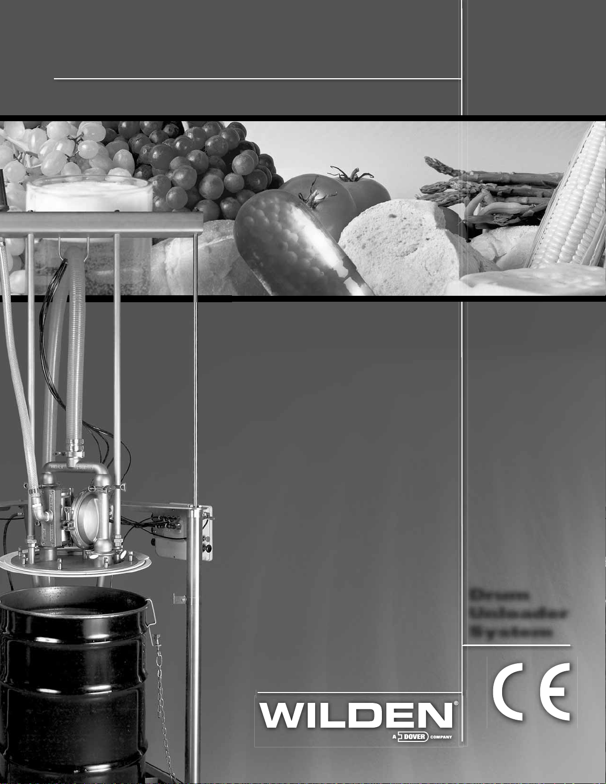
DRUM UNLOADER SYSTEM
Sanifl o™ Series
Refine your process
EOM
Engineering
Operation &
Maintenance
Drum
Unloader
System
REPLACES WIL-12070-E-02
WIL-12070-E-03
Page 2
TABLE OF CONTENTS
SECTION 1 CAUTIONS—READ FIRST! . . . . . . . . . . . . . . . . . . . . . . . . . . . . . . . . . . . . . . . . . . . . . .1
SECTION 2 DESIGNATION SYSTEM. . . . . . . . . . . . . . . . . . . . . . . . . . . . . . . . . . . . . . . . . . . . . . . . .2
SECTION 3 DIMENSIONAL DRAWINGS . . . . . . . . . . . . . . . . . . . . . . . . . . . . . . . . . . . . . . . . . . . . .3
SECTION 4 TROUBLESHOOTING . . . . . . . . . . . . . . . . . . . . . . . . . . . . . . . . . . . . . . . . . . . . . . . . . . . .4
SECTION 5 ASSEMBLY . . . . . . . . . . . . . . . . . . . . . . . . . . . . . . . . . . . . . . . . . . . . . . . . . . . . . . . . . . . . . 5
SECTION 6 OPERATION . . . . . . . . . . . . . . . . . . . . . . . . . . . . . . . . . . . . . . . . . . . . . . . . . . . . . . . . . . .13
SECTION 7 CLEANING . . . . . . . . . . . . . . . . . . . . . . . . . . . . . . . . . . . . . . . . . . . . . . . . . . . . . . . . . . . .17
SECTION 8 SCHEMATICS
A. Control Box . . . . . . . . . . . . . . . . . . . . . . . . . . . . . . . . . . . . . . . . . . . . . . . . . . . . . . . . . .20
B. Hoses . . . . . . . . . . . . . . . . . . . . . . . . . . . . . . . . . . . . . . . . . . . . . . . . . . . . . . . . . . . . . . .21
SECTION 9 EXPLODED VIEW & PARTS LISTING . . . . . . . . . . . . . . . . . . . . . . . . . . . . . . . . . . . .22
Page 3
Section 1
CAUTIONS—READ FIRST!
Drum Unloader System
CAUTION : Always wear safety glasses and appropriate safety
gear when operating the Sanifl o™ DUS unit.
CAUTION : Always perform an inspection of the entire system
before each use. Ensure that all parts are in good working
condition and do not show signs of wear.
WARNING: Prior to installing a Sanifl o™ DUS in to an
application, you must fi rst ensure that the DUS components
are compatible with the process media and any cleaning or
sanitation products.
WARNING: Never attempt to modify the Sanifl o™ DUS unit.
Modifi cation will change the dynamics of the DUS and could
damage the unit, result in failure of the unit, or cause harm to
anyone in the area.
CAUTION : Always disconnect the main air supply to the
Sanifl o™ DUS before service or repairs are attempted. Failure
to do so could result in harm to anyone in the area.
CAUTION : The Sanifl o™ DUS unit must be properly secured
while in use. Failure to properly secure the system while in use
could result in harm to anyone in the area.
CAUTION : When using the Sanifl o™ DUS unit, it is extremely
important to note that the retracting downward movement can
cause a pinch point at two areas of the unit.
1. A pinch point is located at the bottom of the structure when
the ram plate is lowered to the base assembly. To avoid injury
to anybody operating this equipment or to anyone in the area
of the equipment, keep hands, arms and head clear of plate
and drum edge.
2. Another pinch point is located at the area where the ram
support bar comes in the vicinity of the header plate. To avoid
injury t o anyb ody operating this e quipment or to anyone in th e
area of the equipment when it is in operation, a safe distance
must be kept from the ram support bar/header plate area.
CAUTION : Do not exceed 8.6 bar (125 psig) air pressure to the
Sanifl o™ DUS unit .
Do not exceed 1.7 bar (25 psig) air pressure to the RAM DOWN.
For normal operation, 1.0 bar (15 psig) is suggested.
Do not exceed 5.5 bar (80 psig) air pressure to the RAM UP. For
normal operation, 4.1 bar (60 psig) is suggested.
CAUTION : Before attaching an air source to the DUS unit,
inspect all hose connections to ensure they are secure.
CAUTION : Before operating Sanifl o™ DU S unit, a t t ach d rum
retention hooks to secure drum during operation. Failure to
do so will result in drum being moved and/or lifted when ram
assembly is moved upward.
WARNING: It is important to follow the assembly instructions
provided when building the Sanifl o™ DUS unit. Altering the
steps or changing the process may result in operation
issues including improper rise and fall of the follower plate
assembly.
Pump
NOTE: Pump not included with Sanifl o™ DUS. Pump sold
separately.
CAUTION : Do not apply compressed air to the exhaust port
– pump will not operate.
CAUTION : Do not exceed 8.6 bar (125 psig) air supply
pressure.
CAUTION : Do not over-lubricate air supply. Excessive
lubrication will reduce pump performance.
TEMPERATURE LIMITS:
Neoprene –17.7°C to 93.3°C 0°F to 200°F
Buna-N –12.2°C to 82.2°C 10°F to 180°F
EPDM –51.1°C to 137.8°C –60°F to 280°F
Viton
Sanifl ex™ –28.9°C to 104.4°C –20°F to 220°F
Polytetrafl uoroethylene (PTFE)
4.4°C to 104.4°C 40°F to 220°F
Polyurethane –12.2°C to 65.6°C 10°F to 150°F
®
–40.0°C to 176.7°C –40°F to 350°F
CAUTION: Maximum temperature limits are based upon
mechanical stress only. Certain chemicals will signifi cantly
reduce maximum safe operating temperatures. Consult
Chemical Resistance Guide (E4) for chemical compatibility and
temperature limits.
WARNING: Prevention of static sparking – if static sparking
occurs, fi re or explosion could result. Pump, valves, and
containers must be grounded to a proper grounding point
when handling fl ammable fl uids and whenever discharge of
static electricity is a hazard.
CAUTION : The process fl uid and cleaning fl uids must be
chemically compatible with all wetted pump components.
Consult Chemical Resistance Guide (E4).
CAUTION : Do not exceed 82.2°C (180.0°F) air inlet temperature
for Pro-Flo V™ models.
CAUTION : Pumps should be thoroughly fl ushed before
installing into process lines. FDA and USDA approved pumps
should be cleaned and /or sanitized before use.
CAUTION : If diaphragm rupture occurs, material being pumped
may be forced out air exhaust.
CAUTION : Before any maintenance or repair is attempted, the
compressed air line to the pump should be disconnected and
all air pressure allowed to bleed from pump. Disconnect all
intake, discharge and air lines. Drain pump by turning it upside
down and allowing any fl uid to fl ow into a suitable container.
WIL-12070-E-03 1 WILDEN PUMP & ENGINEERING, LLC
Page 4
Section 2
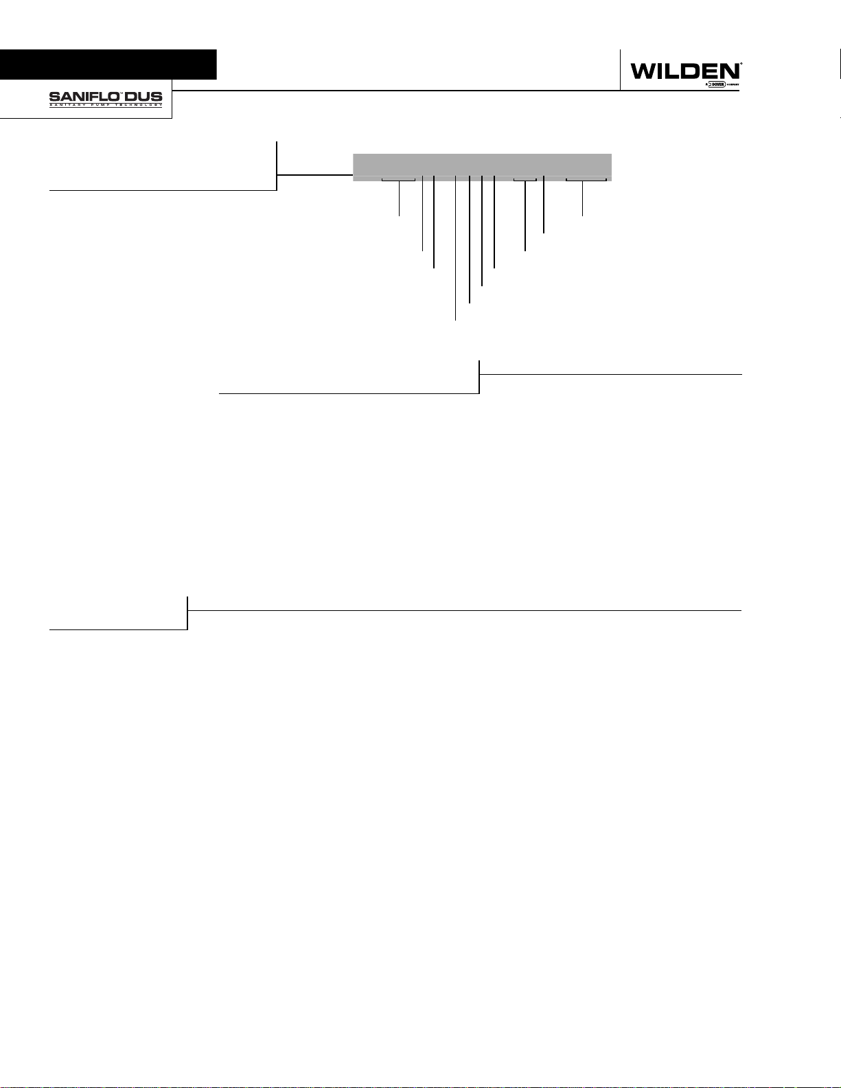
WILDEN DESIGNATION SYSTEM
DRUM UNLOADER
SYSTEM
LEGEND
SANIFLO
MODEL
DUS = DRUM UNLOADER
SYSTEM
PUMP SIZE
4 = 38 mm (1-1/2”) ORIGINAL
SERIES
PUMP TYPE
S = SIMPLEX SINGLE ACTING
D = DUPLEX DOUBLE ACTING
TM
DUS MATERIAL CODES
DUSXX/ XXXX / XXX/ XXXX
MODEL
DRUM SIZE
PUMP SIZE GASKET MATERIAL
PUMP TYPE FRAME MATERIAL
FOLLOW PLATE MATERIAL
CYLINDER MATERIAL
BASE TYPE
BASE TYPE
F = FLOOR MOUNTED
B = BASE PLATE MOUNTED
CYLINDER MATERIAL
S = STAINLESS STEEL
FOLLOW PLATE MATERIAL
S = STAINLESS STEEL
SPECIALTY CODE
FRAME MATERIAL
S = STAINLESS STEEL
GASKET MATERIAL
FB = SANITARY BUNA-N
DRUM SIZE (DIA.)
K = 533 - 557 mm (21.0”-21.9”)
L = 558 - 582 mm (22.0”-22.9”)
SPECIALTY CODES
0070 Saniflo™
WILDEN PUMP & ENGINEERING, LLC 2 WIL-12070-E-03
Page 5
Section 3
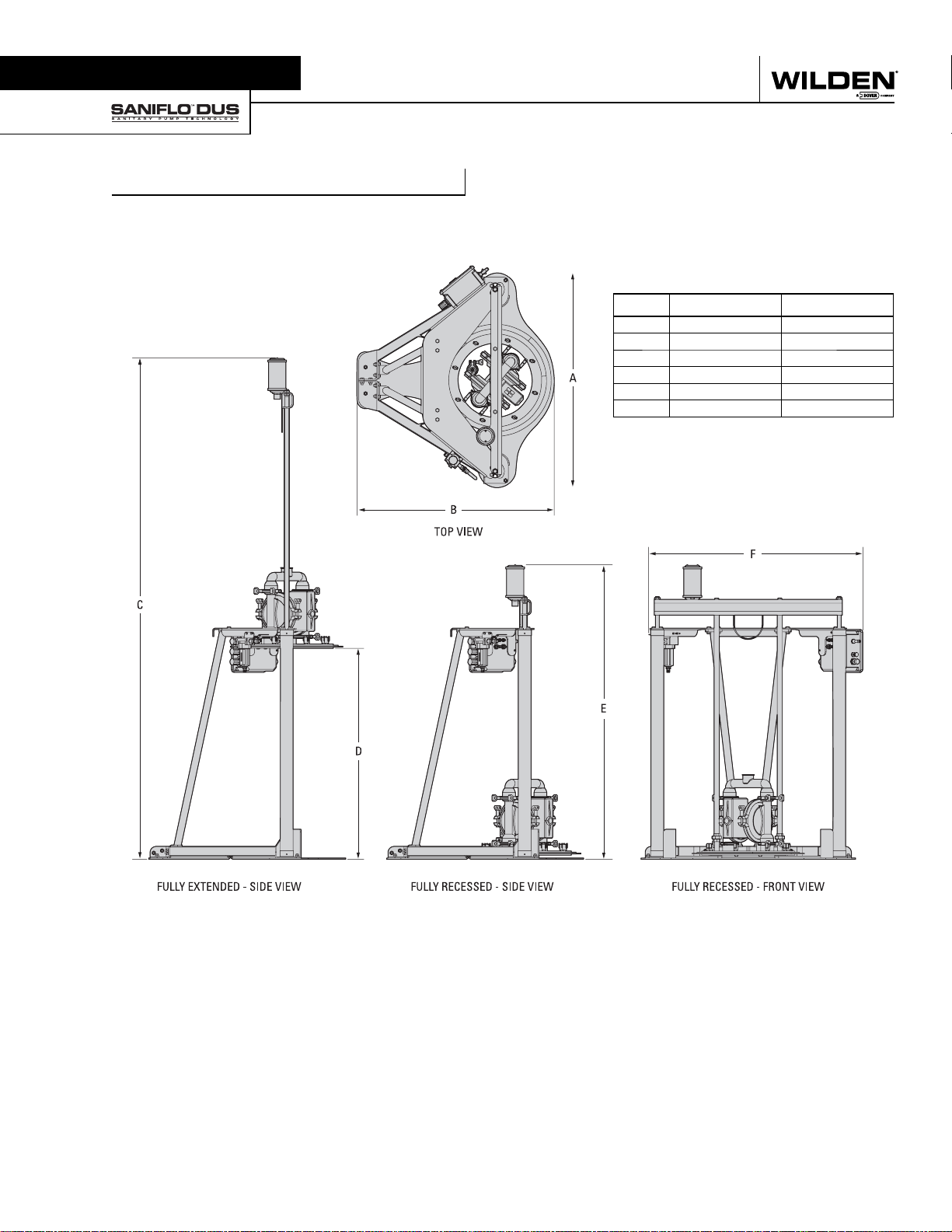
DIMENSIONAL DRAWING
DRUM UNLOADER SYSTEM
DIMENSIONS
ITEM METRIC (mm) STANDARD (inch)
A 1143 45.0
B 1049 41.3
C 2667 105.0
D 1123 44.2
E 1567 61.7
F 1140 44.9
WIL-12070-E-03 3 WILDEN PUMP & ENGINEERING, LLC
Page 6

Section 4
TROUBLESHOOTING
Uneven ram cylinder movement.
1. Ensure that the ram cylinder down pressure is not
excessive. Generally, no more than 1.0 bar (15 psig) is
required to move the ram cylinders in the downward
direction.
2. Check to determine whether or not the ram
cylinder air hoses are connected properly. The
ram down cylinder air hoses consist of two longer
air hoses that are equal in length and one shorter
air hose. The ram up cylinder air hoses consist of
two shorter hoses that are equal in length and one
longer air hose. If the ram cylinder air hoses are
not connected properly, the ram cylinders will fi ll
unevenly, causing the ram cylinder movement to
be inconsistent.
3. It is important to follow the assembly process
(section 5). Altering the steps or changing the
process may result in operation issues including
improper rise and fall of the ram cylinders. Steps 1
through 10 of the assembly process are extremely
critical. Following these steps will ensure that the
ram cylinder movement is unrestricted.
Pump runs but little or no product fl ows.
1. Check for pump cavitation; slow pump speed to
allow thick material to fl ow into liquid chambers.
2. Chec k for sticking b all check valves . If material being
pumped is not compatible with pump elastomers,
swelling may occur. Replace ball check valves and
seats with proper elastomers. Also, as the check
valve balls wear out, they become smaller and can
become stuck in the seats. In this case, replace
balls and seats.
3. Check to ensure that there is suffi cient air pressure
supplied by the ram down regulator on the control
panel.
After evacuating drum contents, ram cylinders are
struggling with upward movement.
1. Check to determine whether or not drum vent
button is activated. This will inject air under the
ram plate and break the vacuum caused when
removing the ram plate from the drum.
Pump air valve freezes.
1. Check for excessive moisture in compressed
air. Either install a dryer or hot air generator
for compressed air. Alternatively, a coalescing
fi lter may be used to remove the water from the
compressed air in some applications.
Air bubbles in pump discharge.
1. Check for ruptured diaphragm.
2. Check tightness of outer pistons.
3. Check tightness of fasteners and integrity of
o-rings and seats, especially at intake manifold.
4. Ensure pipe connections are airtight.
Product comes out air exhaust.
1. Check for diaphragm rupture.
2. Check tightness of outer pistons to shaft.
Excessive drum contents leaking past gaskets.
1. Ensure that the correct gasket size is being used in
accordance with the drum size.
NOTE: The gaskets are NOT designed to completely
seal against sides of drum. Under normal operating
conditions, there will be some slight weeping of
drum contents.
WILDEN PUMP & ENGINEERING, LLC 4 WIL-12070-E-03
Page 7
Section 7 Assembly / disassembly
Section 5
ASSEMBLY
Tools Required :
• 10 mm Hex Head
Wrench
• 12 mm Wrench
• 18 mm Wrench
• Adjustable Wrench
CAUTION: During assembly it is important not to tighten any bolts completely
until specifi cally instructed. This will ensure system alignment and allow for
proper operation. It is also recommended that an appropriate anti-s eize is us ed on
all stainless steel fasteners during assembly.
Although some air fi ttings may come with a pipe sealant already applied, it is
recommended that a pipe sealant be used with all additional air fi ttings during
assembly.
NOTE: It is important to follow the assembly instructions provided when building
the Sanifl o™ DUS unit. Altering the steps or changing the process may result in
operation issues including improper rise and fall of the follower plate assembly.
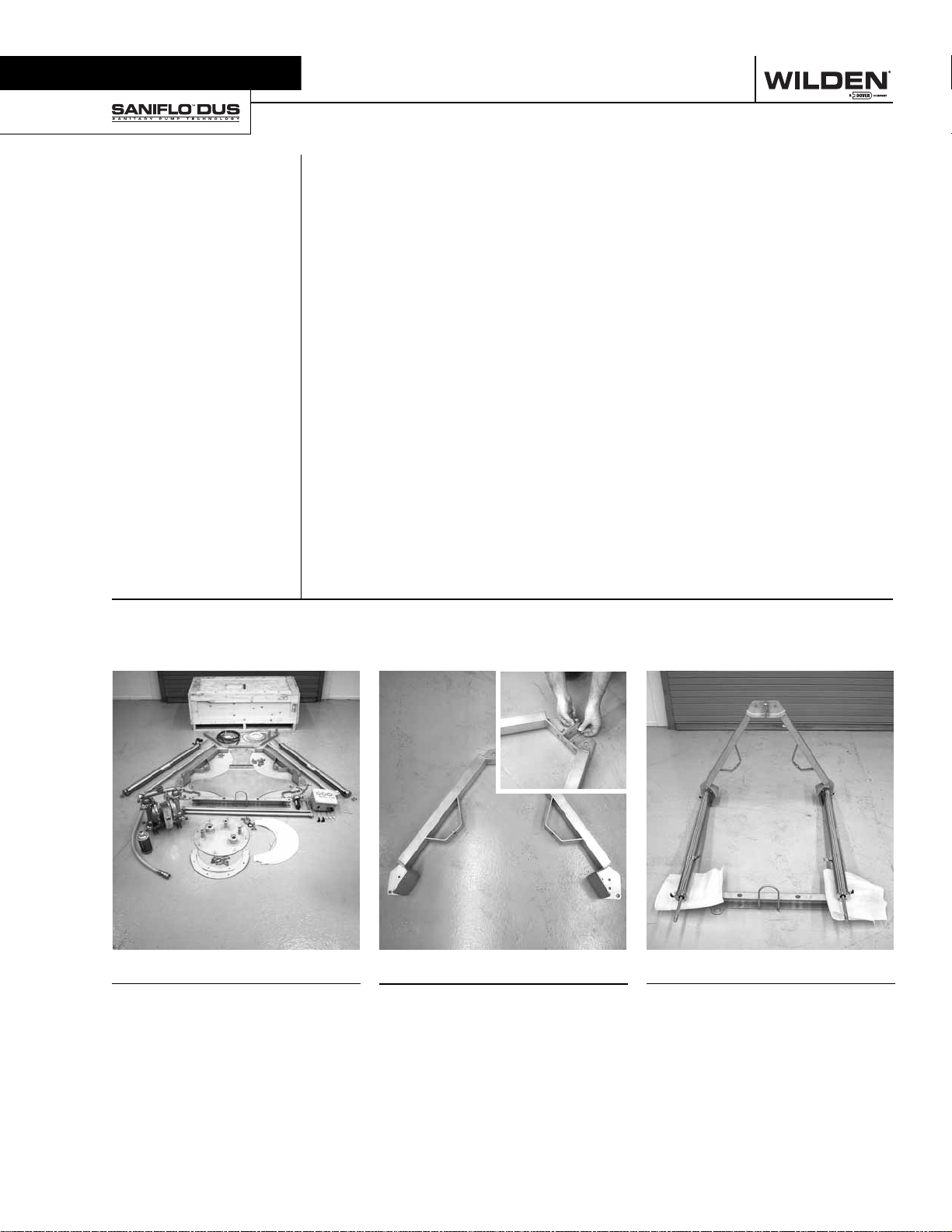
Step 1
Remove all parts from shipping
container and compare with Bill of
Materials listing in Section 9 before
beginning assembly of unit.
WIL-12070-E-03 5 WILDEN PUMP & ENGINEERING, LLC
Step 2
Assemble the left and right base
sections as shown, using two (2) 12
mm bolts, nuts and lock washers.
Leave fasteners hand tight.
Step 3
Raise two connected base pieces
on their side as shown and align
the two pneumatic cylinders. Use
the top support beam to raise the
opposite end of the cylinders for
proper alignment.
Page 8
ASSEMBLY
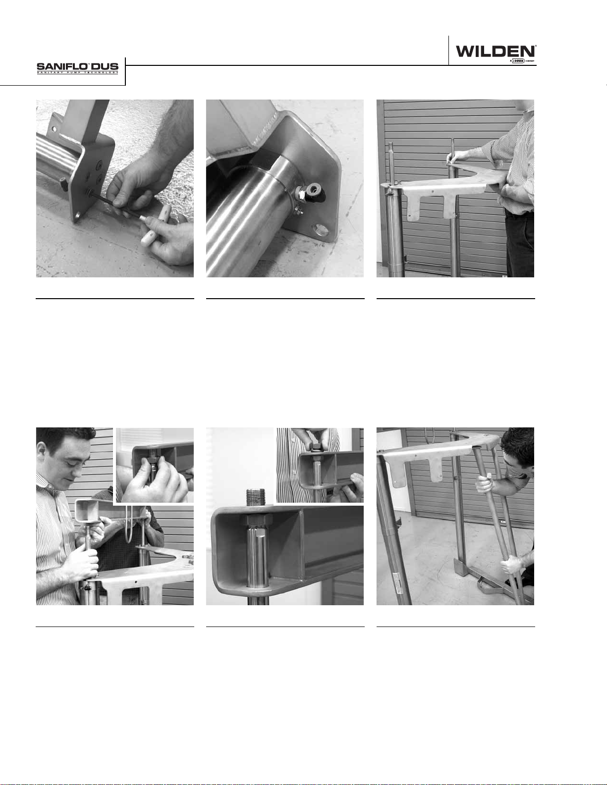
Step 4
Install four (4) 10 mm countersunk
screws in the bottom of the base
frame and end of the cylinders.
NOTE: Once screws are snug, back
off one full turn.
Step 5
When cylinders are installed on
the base frame, ensure that the air
connections are facing away from
the center of the frame assembly.
Step 6
Install the fl at header plate on
the top end of the pneumatic
cylinders. Ensure that the header
plate is positioned as shown when
compared to the base frame.
Step 7
Slide ram support bar over threaded
ends of pneumatic cylinders and
install one (1) 18 mm nut on end of
threaded end until it stops at the rod
shoulder then tighten. NOTE: Nut
should be between upper and lower
support bar holes.
WILDEN PUMP & ENGINEERING, LLC 6 WIL-12070-E-03
Step 8
Slide ram support bar farther down
on the cylinder rod until it bottoms
out on the previously installed nut.
Then add a second 18 mm nut and
lock washer on the end of the rod
and hand tighten.
Step 9
Install braces between base frame
header plate. Triangle end goes up
and rectangular end goes down.
Use 12 mm bolts, nuts and lock
washers and leave hand tight.
Page 9
ASSEMBLY
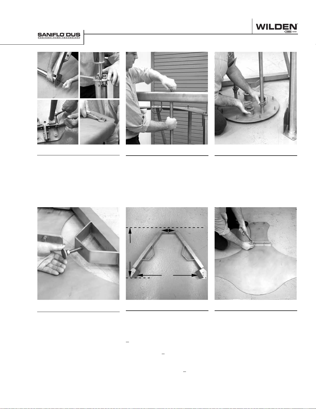
Step 10
Tighten all bolts on the subassembly in the following order:
1. Bottom of cylinders
2. Top of cylinders
3. Base nuts & bolts (fl oor mount
confi guration only)
4. Back braces
Step 11
Install vertical ram support rods
to ram support bar. Use 12 mm
bolts and lock washers and tighten
securely.
B
C
A
Step 12
Install the ram plate on the end of
the vertical ram support bars as
shown. NOTE: The ram plate vent
connection should be toward the
back of the assembly.
Step 13
Install the left and right drum
alignment guides as shown. Final
adjustment will be made later in the
instructions.
WIL-12070-E-03 7 WILDEN PUMP & ENGINEERING, LLC
Step 14A
For floor mounted models,
mm (1/2”) concrete floor anchors. NOTE:
Proper alignment is critical to ensure
proper operation of the system. Dimension
A (mounting bolt holes on the front base
structure) should be 1,060 mm (41.7”)
apart. Dimension B (mounting bolt holes
at the back of the base structure where
both structures are attached) should be
140 mm (5.5”). Dimension C (mounting
bolt holes from front of bottom base
structure to back of structure) should be
763 mm (30.0”).
use 13
Step 14B-1
For base plate mounted models,
assemble the two base pieces
provided using two (2) 12 mm bolts,
nuts and washers. NOTE: Be sure
these are assembled on a fl at surface
to ensure proper alignment. Using
12 mm nuts, bolts and washers,
attach the DUS unit onto the DUS
base plate.
Page 10
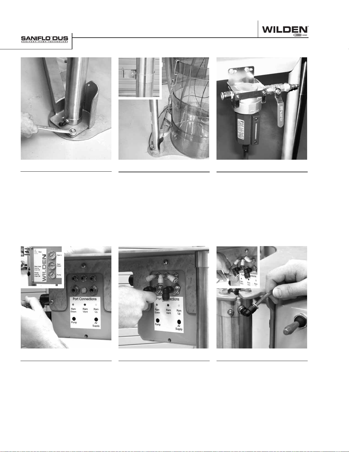
ASSEMBLY
Step 14B-2
For base plate mounted models,
install the sub-assembly built in
steps 1 through 13 to the base
plate using 12 mm bolts, nuts and
washers. Tighten securely.
Step 15
Install the drum retention device
and hanger as shown. NOTE: The
drum hanger should be no higher
than 91 cm (36”) off the fl oor.
Step 16
Install the main air fi lter and shut
off valve on the back of the header
plate with fasteners provided.
Step 17
Install the air control panel with
fasteners provided on the back of
the header plate.
WILDEN PUMP & ENGINEERING, LLC 8 WIL-12070-E-03
Step 18
Install all fi ve air connection fi ttings
on the back of the control panel as
shown.
Step 19
Install the air line from upper
left (ram down) port to the top
connections on the two pneumatic
cylinders.
Page 11
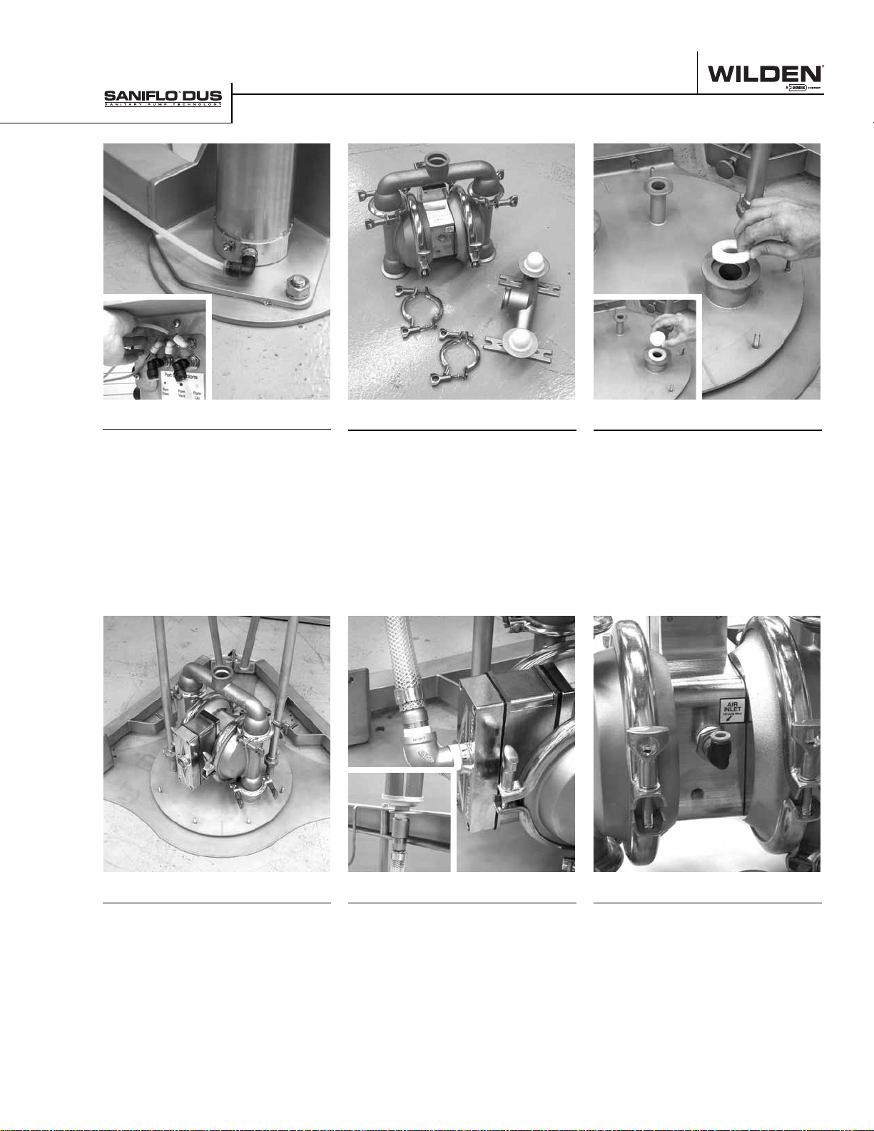
ASSEMBLY
Step 20
Install the air line from upper
right (ram up) port to the bottom
connections on the two pneumatic
cylinders.
Step 21
To install the pump on the DUS
system, fi rst remove the inlet
manifold from the pump.
Step 22
Remove the inlet valve seats and
check balls from the removed
manifold and place in the follower
plate connections.
Step 23
Install the pump on the follower
plate using the clamp bands
provided with the pump. NOTE:
Face the pump exhaust away from
the follower plate vent and align the
bands to allow the free access to
wiper seal bolt ring area.
WIL-12070-E-03 9 WILDEN PUMP & ENGINEERING, LLC
Step 24
Install the exhaust discharge elbow
and hose vertically, with the muffl er
threaded through the eyelet in the
ram support bracket.
Step 25
Install air reducer bushing and
fi tting in the air inlet of the pump.
Page 12
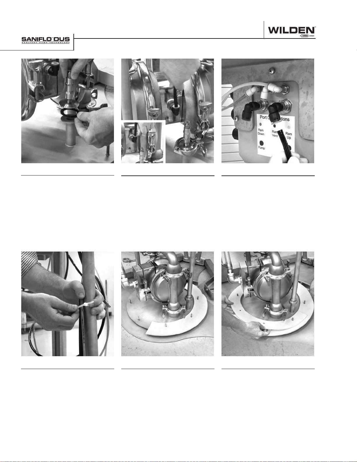
ASSEMBLY
Step 26
Install the ram vent check valve onto
the ram vent port behind the pump.
Use provided clamp band assembly
and o-ring.
Step 27
Install pump air line and ram vent air
lines (green) into fi ttings. Connect
pump air line (black) to bottom left
port on back of panel. Connect vent
air line to upper middle port on back
of panel.
Step 28
Install air line from main fi lter
assembly to lower right port on
back of control panel.
Step 29
Where possible, tie down all air
lines. NOTE: Create enough slack
in the air lines to allow for the ram
assembly to move up and down.
WILDEN PUMP & ENGINEERING, LLC 10 WIL-12070-E-03
Step 30
Install the two (2) pieces of the
larger wiper seal assembly onto the
bolts of the follower plate.
Step 31
Install the two (2) pieces of the
smaller wiper support seal on top
of the main wiper seal. NOTE: Be
sure to rotate the seams between
the two gasket sets to avoid direct
alignment.
Page 13
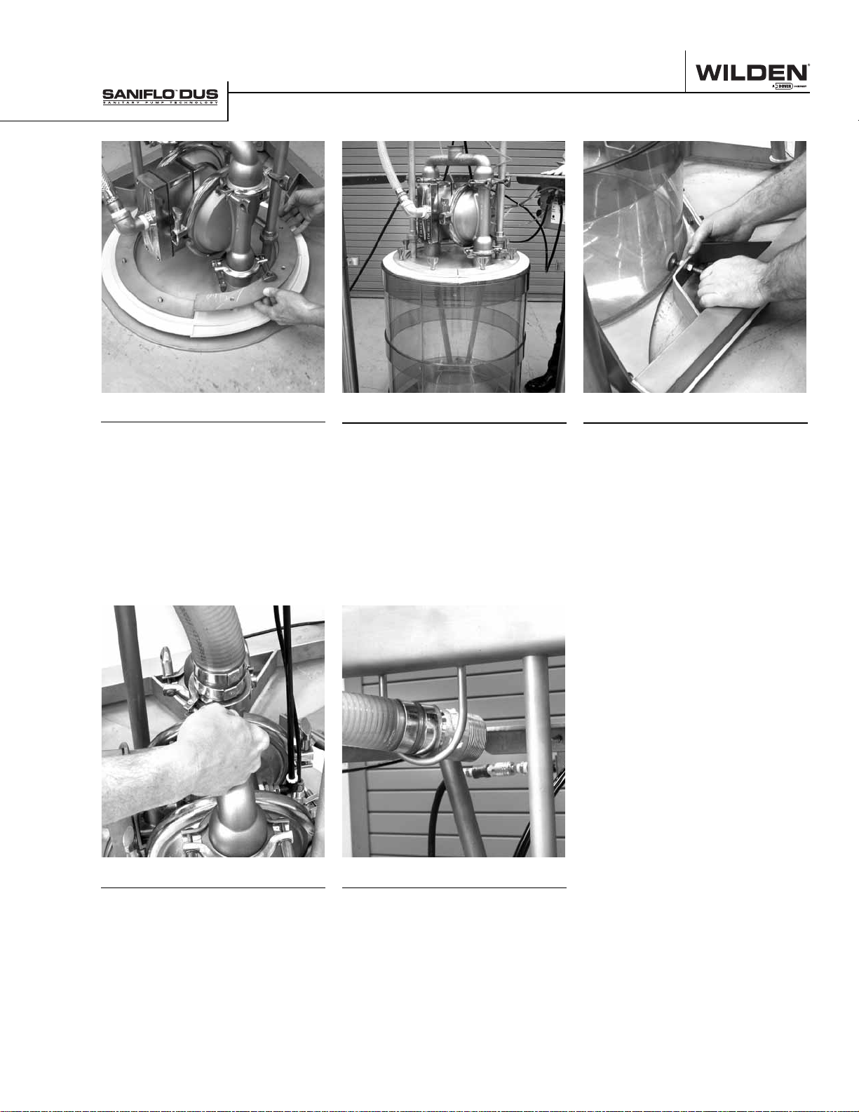
ASSEMBLY
Step 32
Install stainless steel retaining
rings on the follower plate and use
the provided sanitary wing nuts to
secure.
Step 33
In order to set the drum alignment
guide properly, center a drum under
the complete follower plate. To
do this, hook up air supply to the
system and press the “RAM UP”
button on the control panel.
Step 34
Now that the drum is centered
on the follower plate, adjust the
alignment guides to match the drum
size. NOTE: Repeat steps 33 and 34
for a new drum size or if the guides
are inadvertently moved.
Step 35
Install user supplied discharge
hose on the pump using the
necessary reducer, clamp band and
o-rings.
WIL-12070-E-03 11 WILDEN PUMP & ENGINEERING, LLC
Step 36
Thread discharge hose through
support loop on the bottom of the
ram support bar.
Page 14

Section 6
OPERATION
Safety Equipment
Suggestions:
• Safety Glasses
• Protective Clothing
• Safety Shoes or Boots
• Gloves
CAUTION: Always read and familiarize yourself with these operation instructions
prior to using the Sanifl o™ DUS system. Improper use or misapplication could
result in bodily injury or death.
Step 1
Before initial use, or after cleaning
and reassembly, always inspect all
liquid and air connections. Also,
ensure that all frame and pneumatic
cylinder connections are tight.
WIL-12070-E-03 13 WILDEN PUMP & ENGINEERING, LLC
Step 2
Install discharge hose to discharge
of pump. Always use 51 mm (2”)
or larger to prevent excessive
friction losses with high viscosity products. A 64 mm (2-1/2”) or
76 mm (3”) hose is suggested for best
performance.
Step 3
Check pump inlet air supply to
ensure that regulator is set at a
maximum of 8.6 bar (125 psig).
NOTE: Always set the regulator at
the lowest possible air pressure for
the application.
Page 15
OPERATION
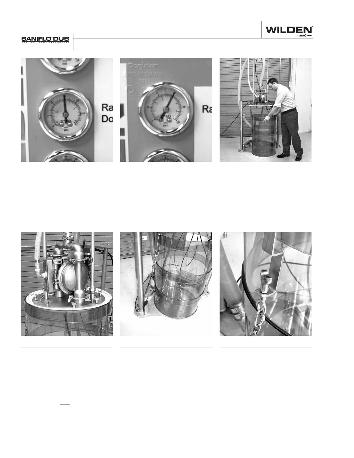
Step 4
To begin process of adjusting RAM
DOWN air supply, first set regulator
to 0 bar (0 psig). Then increase air
pressure until the ram plate comes
in contact with the surface of the
drum contents. Never exceed a
maximum of 1.7 bar (25 psig).
Step 5
Check RAM UP air supply and
ensure that regulator is set to 4.1
bar (60 psig) for normal operation.
Ideally, the pressure should be set
so that the ram plate will slowly
move upward and out of the drum.
Never exceed 5.5 bar (80 psig).
Step 6
Move drum into position under ram
assembly, ensuring that the drum
guides on the bottom of the frame
stop the drum directly centered
under the plate.
Step 7
Check to ensure the proper gasket set is
installed for the drum being unloaded.
NOTE: The larger gasket included in the
gasket set should be 1⁄2” to 1” larger
than the drum diameter and the smaller
gasket should be the same size as the
drum diameter.
The gaskets are NOT designed to completely seal against sides of drum. Under
normal operating conditions, there will be
some slight weeping of drum contents.
WILDEN PUMP & ENGINEERING, LLC 14 WIL-12070-E-03
Step 8
Remove the drum lid to expose
product being pumped and hook
drum retainer hooks over upper
edge of the drum.
Step 9
Tighten drum retainer hooks to
secure the drum in the down
position during operation.
Page 16
OPERATION
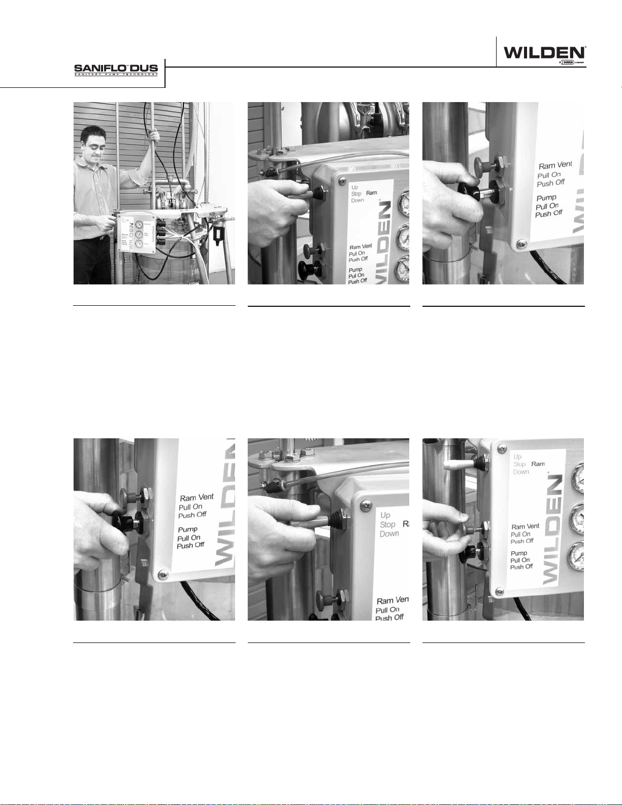
Step 10
When moving the ram in the down
direction, stand towards the right
of the unit and grab the ram plate
support rod with your left hand.
Step 11
To move the ram plate down onto
the product surface, pull the red
lever to the down position. This will
take several seconds as the pneumatic cylinders come up to operating pressure. Ideally, the pressure
should be set so that the ram plate
stops automatically when coming
into contact with product surface.
Step 12
The pump can be started after the
ram plate has come into contact
with the product surface. To start
the pump, pull out the black button
on the side of the control panel.
Step 13
Once the volume of product desired
has been removed from the drum,
or the drum is empty push in on the
black knob to stop pump. NOTE:
The ram control lever can remain in
the down position even if the pump
is not running.
WIL-12070-E-03 15 WILDEN PUMP & ENGINEERING, LLC
Step 14
In preparation for removing the
ram plate from the drum, move the
ram control lever to the middle (off)
position.
Step 15
Pull the green ram vent knob out to
allow positive pressure below the
ram plate to assist with removal.
Page 17
OPERATION
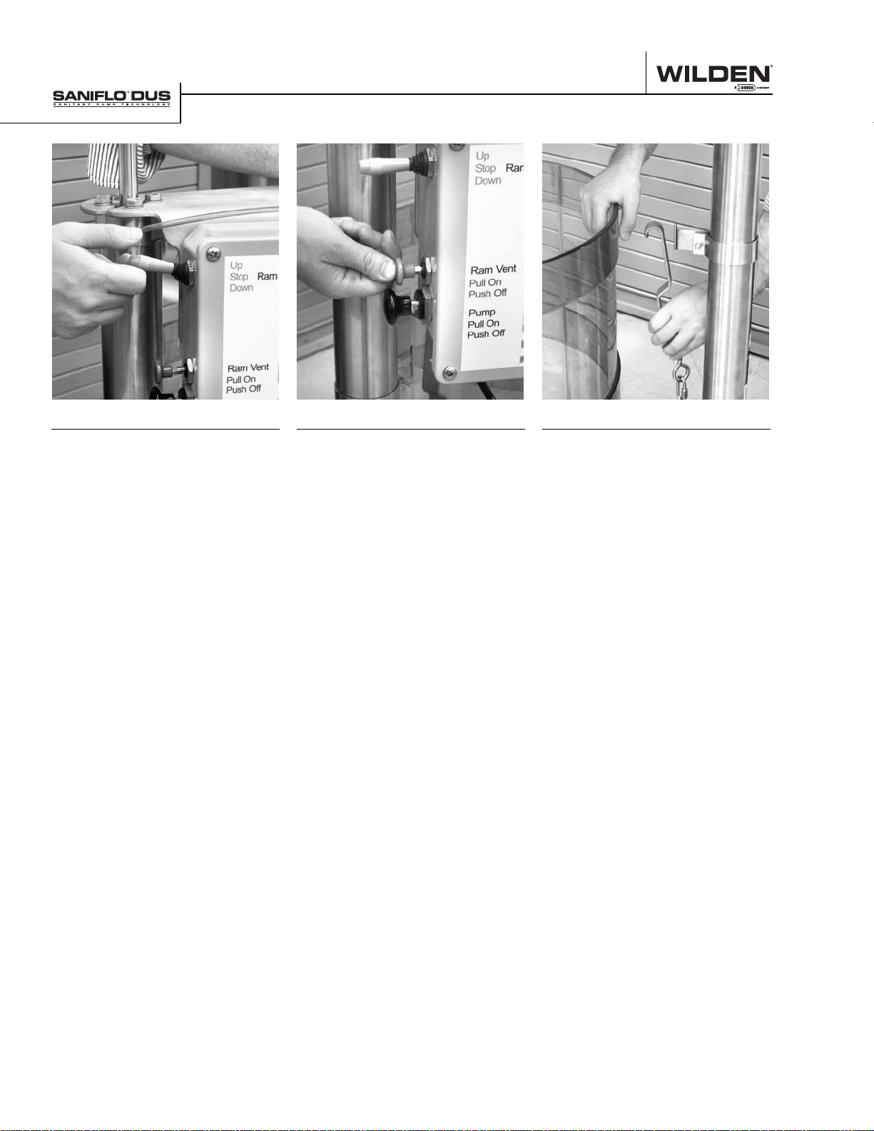
Step 16
To remove the ram plate from the
drum, move the ram control lever
to the up position. Return to the
middle (off) position once the ram
plate has retracted to its full height.
NOTE: Ensure the drum retainers
are in place before starting this
action.
Step 17
Once the ram has cleared the upper
edge of the drum, push in on the
green ram vent knob to stop the air
fl ow coming through the ram vent.
Step 18
Remove drum retention hooks
so that the empty drum can be
removed from the system to make
way for a new drum.
WILDEN PUMP & ENGINEERING, LLC 16 WIL-12070-E-03
Page 18
Section 7 Assembly / disassembly
Section 7
CLEANING
Safety Equipment
Suggestions:
• Safety Glasses
• Protective Clothing
• Safety Shoes or Boots
• Gloves
CAUTION: Always read and familiarize yourself with these operation instructions
prior to using the Sanifl o™ DUS system. Improper use or misapplication could
result in bodily injury or death.
Do not use cleaners containing chlorides such as bleach. Consult cleaning chemical
supplier for cleaning agents compatible with stainless steel and the elastomer
materials used in the pump. Cleaning agents containing caustics and light acids are
generally approved for stainless steel.
Pumps configured for submersible use are recommended to facilitate cleaning and
reduce maintenance costs.
Avoid excessive direct water pressure contact to the control panel and the ram
cylinder seals.
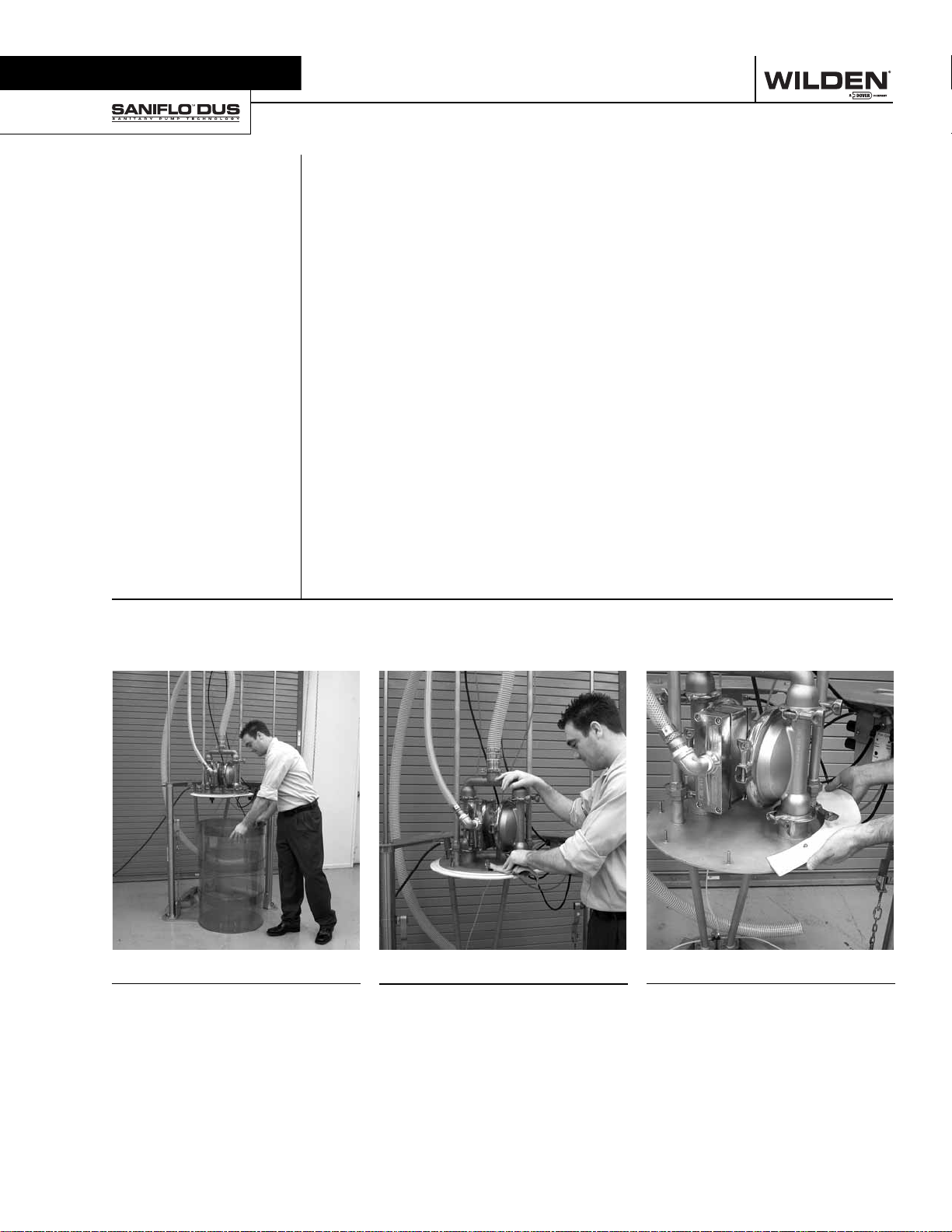
Step 1
Before starting the cleaning process,
remove the product drum from the
system.
WIL-12070-E-03 17 WILDEN PUMP & ENGINEERING, LLC
Step 2
Before starting detailed cleaning of
the unit, wash down the system to
remove any build up on ram plate,
exterior of pump, hoses and/or
frame.
Step 3
Remove gasket retaining ring and
both gasket sets from the ram plate
and clean each item and entire
area.
Page 19
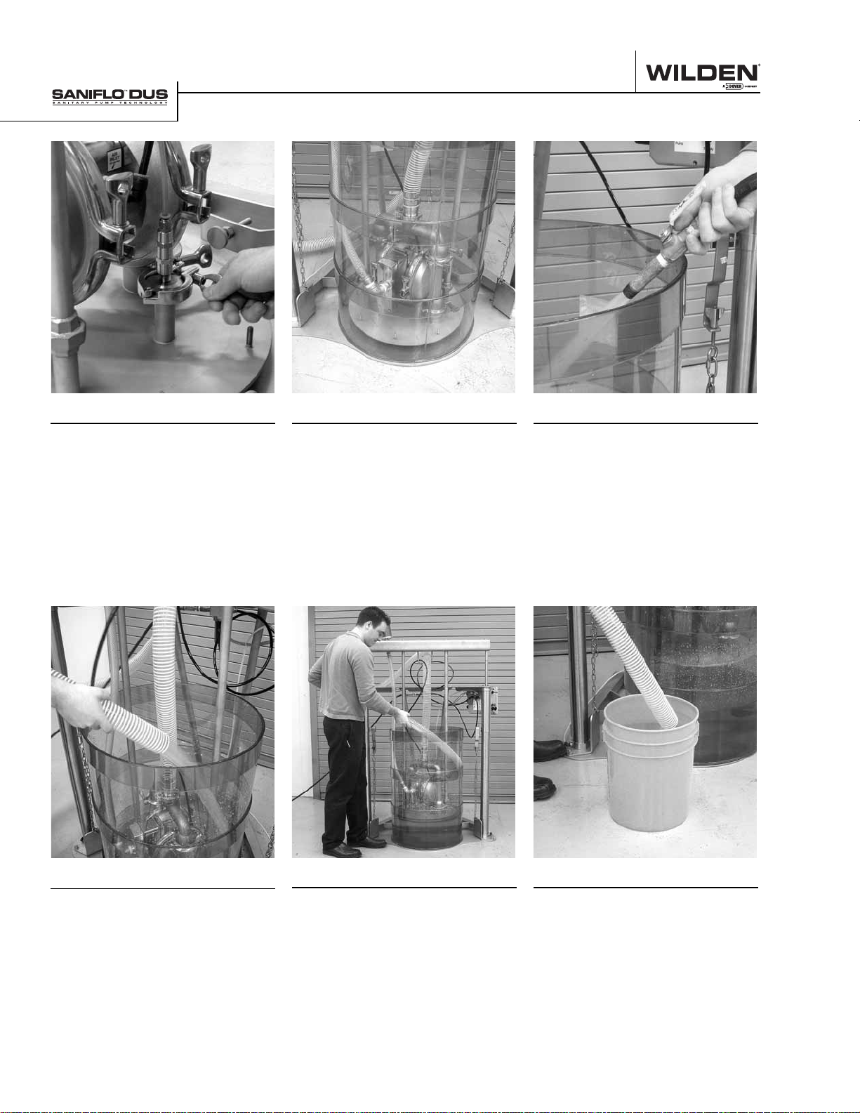
CLEANING
Step 4
Remove ram vent assembly, then
clean and inspect.
Step 5
Lower ram plate with pump down
into clean, empty drum. Stop the
ram plate about 25 mm (1”) from
the bottom of the drum.
Step 6
Add water with cleaning solution
to the drum and start pump by
pulling black pump knob out on
control panel. NOTE: The pump
can be submerged during this
cleaning process if you're using a
submersible Pro-Flo V™ model.
To order a Pro-Flo V™ submersible
pump use specialty code 320.
Step 7
Continue to supply water and
cleaning solution to the pump,
allowing the pump to run until the
discharge of the pump/system runs
clear.
WILDEN PUMP & ENGINEERING, LLC 18 WIL-12070-E-03
Step 8
Once water runs clear, put discharge
hose back into drum and allow
system to circulate water and
cleaning solution for a minimum of
two minutes.
Step 9
After circulating cleaning solution
for a minimum of two minutes,
discharge remaining fl uid to a
suitable drain or collection system.
Refi ll the drum one more time and
allow pump to fl ush system until all
fl uid is removed.
Page 20
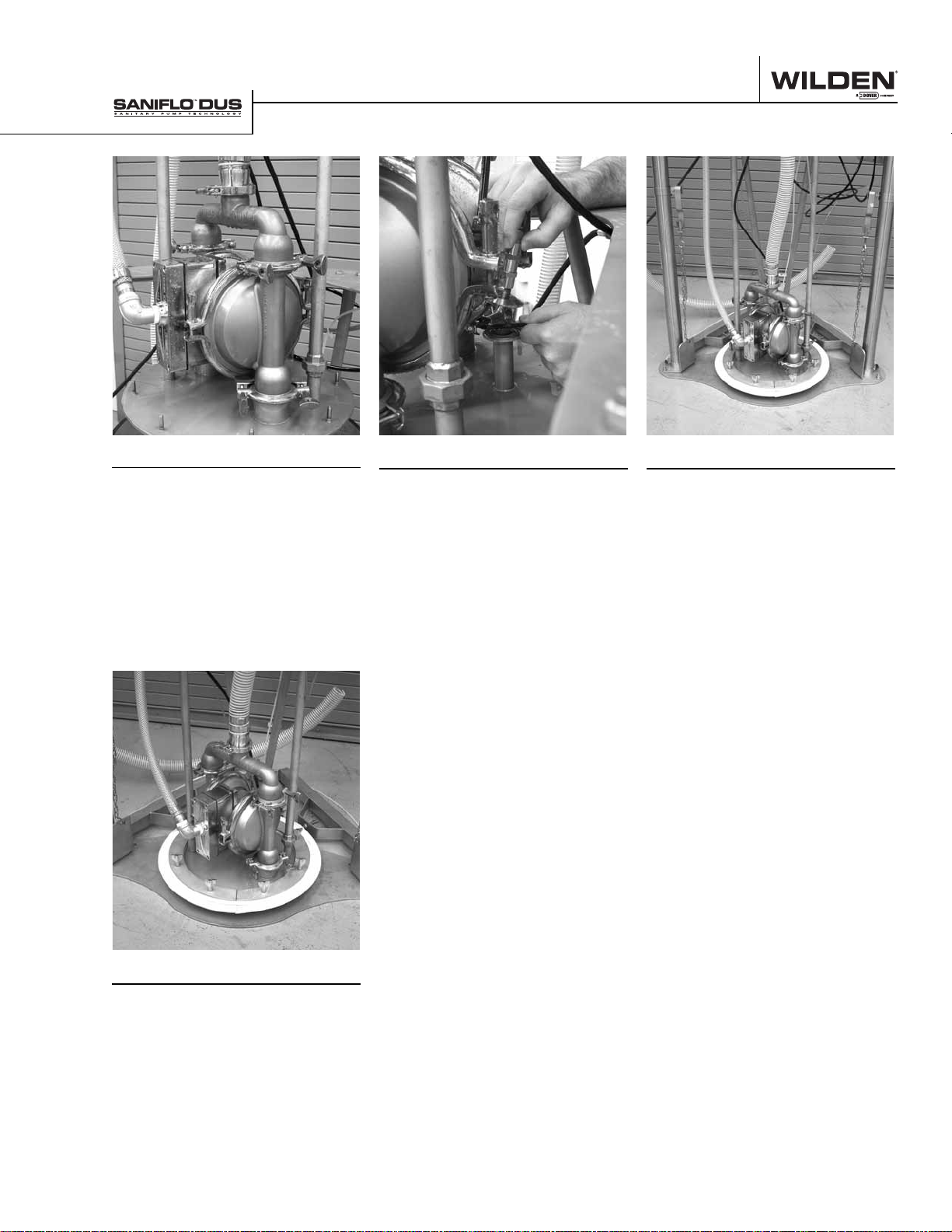
CLEANING
Step 10
Raise the ram plate while the pump
continues to run. This will help
remove any remaining water from
the pump and discharge lines. Once
above the rim of the drum, turn the
pump off.
Step 11
Reinstall the ram vent and gasket.
Step 12
If the unit will not be used on another
product immediately, lower the ram
plate to the fl oor for safety and turn
the air supply off.
Step 13
As each product is different,
and each application may have
different cleaning requirements, it
may be necessary to remove and
disassemble the pump to ensure
proper cleaning.
WIL-12070-E-03 19 WILDEN PUMP & ENGINEERING, LLC
Page 21
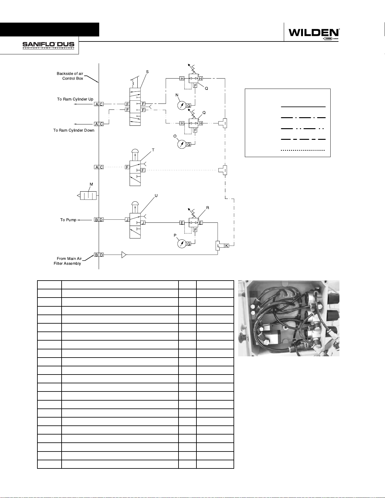
Section 8A
CONTROL BOX SCHEMATICS
Tubing Legend
3/8" Black
1/4" Black
1/4" Red
1/4" Yellow
1/4" Green
ITEM NO. DESCRIPTION QTY. PART NO.
A FITTING - 1/4" TUBE X 1/4" SOCKET - ELBOW 3 DUS-4009
B FITTING - 3/8" TUBE X 3/8" SOCKET - ELBOW 2 DUS-4010
C FITTING - 1/4" TUBE X 1/4" TUBE - BULKEAD UNION 3 DUS-4012
D FITTING - 3/8" TUBE X 3/8" TUBE - BULKEAD UNION 2 DUS-4011
E FITTING - 3/8" TUBE X 3/8" NPT - BANJO ELBOW 2 DUS-4007
F FITTING - 1/4" TUBE X 1/8" NPT - BANJO ELBOW 9 DUS-4008
G FITTING - 1/4" TUBE X 1/8" FNPT - STRAIGHT 3 DUS-4017
H FITTING - 1/4" TUBE X 1/4" NPT - BANJO ELBOW 4 DUS-4006
I FITTING - 1/4" TUBE - TEE 2 DUS-4014
J FITTING - 3/8" TUBE X 1/4" NPT - BANJO ELBOW 2 DUS-4004
K FITTING - 3/8" SOCKET X 1/4" TUBE - REDUCER 1 DUS-4016
L FITTING - 3/8" TUBE - TEE 1 DUS-4015
M FLUSH MUFFLER 1 DUS-4018
N PRESSURE GAUGE - 0 TO 100 PSI 1 DUS-5002
O PRESSURE GAUGE - 0 TO 30 PSI 1 DUS-5003
P PRESSURE GAUGE - O TO 160 PSI 1 DUS-5004
Q REGULATOR - 1/4" WITH 1/4" NPT PORTS 2 DUS-5007
R REGULATOR - 1/4" WITH 3/8" NPT PORTS 1 DUS-5008
S VALVE - RAM CYLINDER CONTROL - RED 3 POSITION LEVER 1 DUS-5006
T VALVE - RAM VENT CONTROL - GREEN PUSH/PULL BUTTON 1 DUS-5009
U VALVE - PUMP CONTROL - BLACK PUSH/PULL BUTTON 1 DUS-5010
CAUTION: Before performing
maintenance on the DUS control
panel, ensure that all air pressure is
removed from system.
WILDEN PUMP & ENGINEERING, LLC 20 WIL-12070-E-03
Page 22
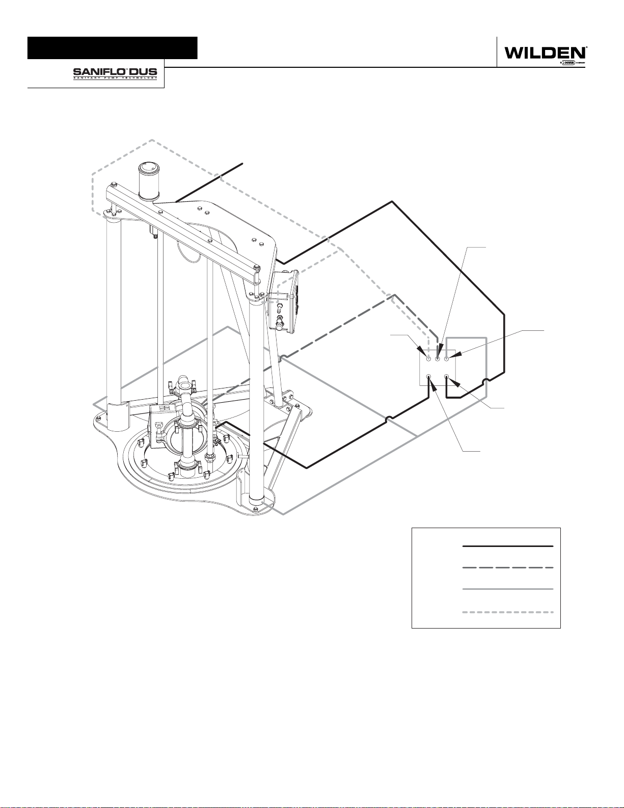
Section 8B
HOSE SCHEMATIC
Air Supply
to Regulator
RAM
VENT
CONTROL BOX
CAUTION: Prior to operating the DUS unit, ensure that
the air hoses are connected and secured properly.
CAUTION: Always wear safety glasses when operating
the DUS unit.
RAM
DOWN
REAR
RAM
UP
AIR
SUPPLY
PUMP
Black
Green
Yellow
Red
WIL-12070-E-03 21 WILDEN PUMP & ENGINEERING, LLC
Page 23
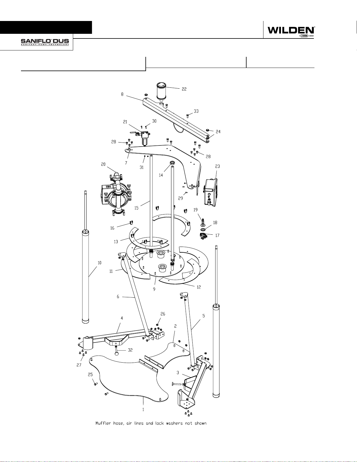
Section 9
EXPLODED VIEW AND PARTS LISTING
DRUM UNLOADER SYSTEM
EXPLODED VIEW
WILDEN PUMP & ENGINEERING, LLC 22 WIL-12070-E-03
Page 24
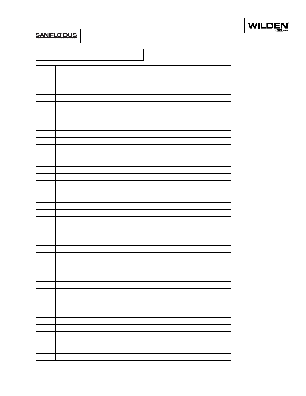
EXPLODED VIEW AND PARTS LISTING
DRUM UNLOADER SYSTEM
Item No. Description Qty. Part No.
1 Floor Plate - Front/Barrel section; 304 SS 1 DUS-2006
2 Floor Plate - Back Section; 304 SS 1 DUS-2007
3 Right Bottom Structure, 304 SS 1 DUS-2005
4 Left Bottom Structure; 304 SS 1 DUS-2004
5 Right Back Support Braces; 304 SS 1 DUS-2003
6 Left Back Support Braces; 304 SS 1 DUS-2002
7 Header Plate, 304 SS 1 DUS-2001
8 Ram Cylinder Cross Connection Beam, 304 SS 1 DUS-2008
9 Ram Plate, 304 SS 1 DUS-2010
10 Ram Cylinder, 304 Stainless Steel 2 DUS-1001
11 Gasket - Split Food Grade Nitrile - 21-1/2" dia. ('K' Gasket) 1 DUS-3001
11 Gasket - Split Food Grade Nitrile - 22-1/2" dia. ('L' Gasket) 1 DUS-3004
12 Gasket - Split Food Grade Nitrile - 22-1/2" dia. ('K' Gasket) 1 DUS-3004
12 Gasket - Split Food Grade Nitrile - 23-1/2" dia. ('L' Gasket) 1 DUS-3002
13 Gasket retaining ring; 304 SS 1 DUS-2011
14 Support Rods Union Nuts; 304 SS 2 DUS-2013
15 Ram Plate Support Rods; 304 SS 2 DUS-2012
16 Sanitary Wing Nut - 5/16" 8 DUS-6011
17 1" Tri-Clamp with Sanitary Wing Nut 1 DUS-3006
18 Ram Vent Gasket 1 DUS-3005
19 Ram Vent Check Valve Assembly. 1 DUS-9005
20 Pump 1 Call Factory
21 3/8" Air Filter 1 DUS-5005
22 Pump Muffl er 1 15-3510-06R
23 Control Box Assembly 1 Call Factory
24 M18X1.5 Hex Nut 4 DUS-1002
Lock Washer - M18 - 18.8 Stainless Steel (not shown) 2 DUS-6034
25 M12X1.75X30 mm Hx Bolt 18.8 Stainless Steel 14 DUS-6004
26 M12X1.75 Hx Nut 18.8 Stainless Steel 18 DUS-6005
Lock Washer - M12 - 18.8 Stainless Steel (not shown) 18 DUS-6006
27 M10X1.5X20 mm Flat Sock Cap 18.8 Stainless Steel 8 DUS-6001
28 M10X1.5X20 mm HX Bolt 18.8 Stainless Steel 8 DUS-6002
Flat Washer - M10 - 18.8 Stainless Steel (not shown) 8 DUS-6003
29 M6X16 Pan Phillips 18.8 Stainless Steel 7 DUS-6007
Lock Washer - M6 - 18.8 Stainless Steel (not shown) 5 DUS-6008
30 M6X1X30 Hx Bolt 18.8 Stainless Steel 2 DUS-6010
M6 Lock Washer 18.8 Stainless Steel (not shown) 5 DUS-6008
31 M6X1.00 Hx Nut 18.8 Stainless Steel 2 DUS-6009
32 Barrel Centering device; 304 SS 2 DUS-2009
33 M12X1.75X30 mm Hx Bolt 18.8 Stainless Steel 2 DUS-6004
PARTS LISTING
WIL-12070-E-03 23 WILDEN PUMP & ENGINEERING, LLC
Page 25
WILDEN PUMP & ENGINEERING, LLC 24 WIL-12070-E-03
Page 26
WARRANTY
Each and every product manufactured by Wilden Pump and Engineering, LLC is built to meet the highest
standards of quality. Every pump is functionally tested to insure integrity of operation.
Wilden Pump and Engineering, LLC warrants that pumps, accessories and parts manufactured or supplied by
it to be free from defects in material and workmanship for a period of five (5) years from date of installation or
six (6) years from date of manufacture, whichever comes first. Failure due to normal wear, misapplication, or
abuse is, of course, excluded from this warranty.
Since the use of Wilden pumps and parts is beyond our control, we cannot guarantee the suitability of any pump
or part for a particular application and Wilden Pump and Engineering, LLC shall not be liable for any consequential
damage or expense arising from the use or misuse of its products on any application. Responsibility is limited
solely to replacement or repair of defective Wilden pumps and parts.
All decisions as to the cause of failure are the sole determination of Wilden Pump and Engineering, LLC.
Prior approval must be obtained from Wilden for return of any items for warranty consideration and must be
accompanied by the appropriate MSDS for the product(s) involved. A Return Goods Tag, obtained from an
authorized Wilden distributor, must be included with the items which must be shipped freight prepaid.
The foregoing warranty is exclusive and in lieu of all other warranties expressed or implied (whether written or oral)
including all implied warranties of merchantability and fitness for any particular purpose. No distributor or other
person is authorized to assume any liability or obligation for Wilden Pump and Engineering, LLC other than expressly
provided herein.
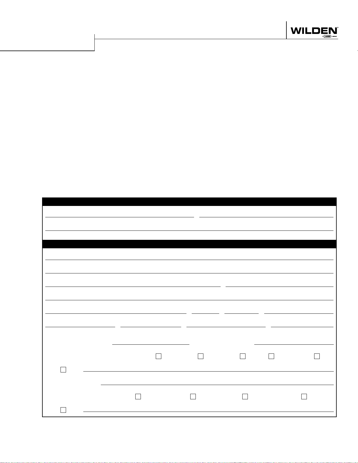
PLEASE PRINT OR TYPE AND FAX TO WILDEN
PUMP INFORMATION
Item # Serial #
Company Where Purchased
YOUR INFOR MATION
Company Name
Industry
Name Title
Street Address
City State Postal Code Country
Telephone Fax E-mail Web Address
Number of pumps in facilit y? Number of Wilden pumps?
Types of pumps in facility (check all that apply): Diaphragm Centrifugal Gear Submersible Lobe
Other
Media being pumped?
How did you hear of Wilden Pump? Trade Journal Trad e Sho w Internet/E-mail Distributor
Other
ONCE COMPLETE, FAX TO (909) 783-3440
NOTE: WARRANTY VOID IF PAGE IS NOT FA XED TO WILDEN
WILDEN PUMP & ENGINEERING, LLC
 Loading...