

Wilden P800, PX800 Engineering, Operation & Maintenance
P800/PX800
Advanced™ Series PLASTIC Pumps
Advance your process
Engineering
Operation &
Maintenance
TO REPL ACE WIL-11250- E- 02
WIL-11250-E-03

TABLE OF CONTENTS
SECTION 1 CAUTIONS—READ FIRST! . . . . . . . . . . . . . . . . . . . . . . . . . . . . . . . . . . . . . . . . . . . . . .1
SECTION 2 WILDEN PUMP DESIGNATION SYSTEM . . . . . . . . . . . . . . . . . . . . . . . . . . . . . . . . .2
SECTION 3 HOW IT WORKS—PUMP & AIR DISTRIBUTION SYSTEM . . . . . . . . . . . . . . . . 3
SECTION 4 DIMENSIONAL DRAWINGS . . . . . . . . . . . . . . . . . . . . . . . . . . . . . . . . . . . . . . . . . . . . .4
SECTION 5 PERFORMANCE
A. P800 Performance Curves
Rubber-Fitted . . . . . . . . . . . . . . . . . . . . . . . . . . . . . . . . . . . . . . . . . . . . . . . . . . . . . . . .6
TPE-Fitted . . . . . . . . . . . . . . . . . . . . . . . . . . . . . . . . . . . . . . . . . . . . . . . . . . . . . . . . . . .6
Reduced Stroke PTFE-Fitted . . . . . . . . . . . . . . . . . . . . . . . . . . . . . . . . . . . . . . . . . . . .7
Full Stroke-Fitted . . . . . . . . . . . . . . . . . . . . . . . . . . . . . . . . . . . . . . . . . . . . . . . . . . . . .7
Ultra-Flex™-Fitted . . . . . . . . . . . . . . . . . . . . . . . . . . . . . . . . . . . . . . . . . . . . . . . . . . . .8
Suction Lift Curve . . . . . . . . . . . . . . . . . . . . . . . . . . . . . . . . . . . . . . . . . . . . . . . . . . . .9
B. PX800 Performance Curves
Operating Principal . . . . . . . . . . . . . . . . . . . . . . . . . . . . . . . . . . . . . . . . . . . . . . . . . . . .12
How to Use this EMS Curve . . . . . . . . . . . . . . . . . . . . . . . . . . . . . . . . . . . . . . . . . . . . .13
Performance Curves
Rubber-Fitted . . . . . . . . . . . . . . . . . . . . . . . . . . . . . . . . . . . . . . . . . . . . . . . . . . . .16
TPE-Fitted . . . . . . . . . . . . . . . . . . . . . . . . . . . . . . . . . . . . . . . . . . . . . . . . . . . . . . .17
Reduced Stroke PTFE-Fitted . . . . . . . . . . . . . . . . . . . . . . . . . . . . . . . . . . . . . . . .18
Full Stroke-Fitted . . . . . . . . . . . . . . . . . . . . . . . . . . . . . . . . . . . . . . . . . . . . . . . . . .19
Ultra-Flex™-Fitted . . . . . . . . . . . . . . . . . . . . . . . . . . . . . . . . . . . . . . . . . . . . . . . . 20
Suction Lift Curve . . . . . . . . . . . . . . . . . . . . . . . . . . . . . . . . . . . . . . . . . . . . . . . . . . .21
SECTION 6 SUGGESTED INSTALLATION, OPERATION & TROUBLESHOOTING . . . . . . . 23
SECTION 7 DISASSEMBLY/REASSEMBLY
Pump Disassembly . . . . . . . . . . . . . . . . . . . . . . . . . . . . . . . . . . . . . . . . . . . . . . . . . . . . . . .25
Pro-Flo® Air Valve / Center Section Disassembly . . . . . . . . . . . . . . . . . . . . . . . . . . . . . . . 29
TM
Pro-Flo X
Reassembly Hints & Tips . . . . . . . . . . . . . . . . . . . . . . . . . . . . . . . . . . . . . . . . . . . . . . . . . . 34
Air Valve / Center Section Disassembly . . . . . . . . . . . . . . . . . . . . . . . . . . . . 32
SECTION 8 EXPLODED VIEW & PARTS LISTING
P800 PLASTIC
P800 Full Stroke-Fitted . . . . . . . . . . . . . . . . . . . . . . . . . . . . . . . . . . . . . . . . . . . . . . . . .36
P800 Reduced Stroke-Fitted . . . . . . . . . . . . . . . . . . . . . . . . . . . . . . . . . . . . . . . . . . . . .38
P800 PLASTIC
PX800 Full Stroke-Fitted . . . . . . . . . . . . . . . . . . . . . . . . . . . . . . . . . . . . . . . . . . . . . . . .40
PX800 Reduced Stroke-Fitted . . . . . . . . . . . . . . . . . . . . . . . . . . . . . . . . . . . . . . . . . . . .42
SECTION 9 ELASTOMER OPTIONS . . . . . . . . . . . . . . . . . . . . . . . . . . . . . . . . . . . . . . . . . . . . . . . . .44
Section 1
CAUTIONS—READ FIRST!
CAUTION: Do not apply compressed air to the
exhaust port — pump will not function.
CAUTION: Do not over-lubricate air supply —
excess lubrication will reduce pump performance.
Pump is pre-lubed.
TEMPERATURE LIMITS:
Neoprene –17.7°C to 93.3°C 0°F to 200°F
Buna-N –12.2°C to 82.2°C 10°F to 180°F
EPDM –51.1°C to 137.8°C –60°F to 280°F
Viton
Sanifl ex™ –28.9°C to 104.4°C –20°F to 220°F
Polytetrafl uoroethylene (PTFE)
4.4°C to 104.4°C 40°F to 220°F
Polyurethane –12.2°C to 65.6°C 10°F to 150°F
Tetra-Flex™ PTFE w/Neoprene Backed
4.4°C to 107.2°C 40°F to 225°F
Tetra-Flex™ PTFE w/EPDM Backed
-10°C to 137°C 14°F to 280°F
Wil-Flex™ -40°C to 107.2°C (-40°F to 225°F)
®
–40°C to 176.7°C –40°F to 350°F
NOTE: Not all materials are available for all
models. Refer to Section 2 for material options
for your pump.
CAUTION: When choosing pump materials, be
sure to check the temperature limits for all wetted
components. Example: Viton® has a maximum
limit of 176.7°C (350°F) but polypropylene has a
maximum limit of only 79°C (175°F).
CAUTION: Maximum temperature limits are
based upon mechanical stress only. Certain
chemicals will signifi cantly reduce maximum
safe operating temperatures. Consult Chemical
Resistance Guide (E4) for chemical compatibility
and temperature limits.
WARNING: Prevention of static sparking — If
static sparking occurs, fi re or explosion could
result.
CAUTION: Always wear safety glasses when
operating pump. If diaphragm rupture occurs,
material being pumped may be forced out air
exhaust.
CAUTION: Before any maintenance or repair is
attempted, the compressed air line to the pump
should be disconnected and all air pressure
allowed to bleed from pump. Disconnect all
intake, discharge and air lines. Drain the pump
by turning it upside down and allowing any fl uid
to fl ow into a suitable container.
CAUTION: Blow out air line for 10 to 20 seconds
before attaching to pump to make sure all pipeline
debris is clear. Use an in-line air fi lter. A 5µ (micron)
air fi lter is recommended.
CAUTION: If the pipe plug in the inlet or discharge
manifold on the 51 mm (2") Advanced™ plastic
center-ported model is removed, a triple density
(red) PTFE pipe tape is recommended to ensure
adequate sealing.
NOTE: When installing PTFE diaphragms, it is
important to tighten outer pistons simultaneously
(t ur ning in oppo site direc tions) to ensure tight fi t.
(See torque specifi cations in Section 7.)
NOTE: Before starting disassembly, mark a line
from each liquid chamber to its corresponding air
chamber. This line will assist in proper alignment
during reassembly.
CAUTION: Pro-Flo® pumps cannot be used in
submersible applications. Pro-Flo X™ is available
in both submersible and non-submersible
options. Do not use non-submersible Pro-Flo X™
models in submersible applications.
CAUTION: Tighten all hardware prior to installation.
CAUTION: Do not exceed 8.6 bar (125 psig) air
supply pressure.
CAUTION: The process fl uid and cleaning fl uids
must be chemically compatible with all wetted
pump components. Consult Chemical Resistance
Guide (E4).
CAUTION: Do not exceed 82°C (180°F) air inlet
temperature for Pro-Flo X™ models.
WIL-11250-E-03 1 WILDEN PUMP & ENGINEERING, LLC
Section 2
WILDEN PUMP DESIGNATION SYSTEM
P800/PX800 PLASTIC
51 mm (2") Pump
Maximum Flow Rate:
693 lpm (183 gpm)
LEGEND
MATERIAL CODES
MODEL
P800 = PRO-FLO
PX8 00 = PRO-F LO X™
WETTED PARTS
KK = PVDF / PVDF
PK = POLYPROPYLENE / PVDF
AIR CHAMBERS
P = POLYPROP YLENE
CENTER BLOCK
P = POLYPROP YLENE
AIR VALVE
P = POLYPROP YLENE
L = ACETAL (P800 only)
®
PX800 / XXXXX / XXX / XX/ XXX / XXXX
MODEL
VALVE BALLS
DIAPHRAGMS
AIR VALVE
CENTER BLOCK
AIR CHAMBERS
WETTED PARTS & OUTER PISTON
DIAPHRAGMS
BNS = BUNA-N (Red Dot)
BNU = BUNA-N, ULTRA-FLEX™
EPS = EPDM (Blue Dot)
EPU = EPDM, ULTRA-FLEX™
FSS = SANIFLEX™
[Hytrel® (Cream)]
NES = NEOPRENE (Green Dot)
NEU = NEOPRENE, ULTRA-FLEX™
PUS = POLYURETHANE (Clear)
TEU = PTFE W/EPDM
BACK-UP (White)
TNU = PTFE W/NEOPRENE
BACK-UP (White)
TSU = PTFE W/SANIFLEX™
BACK-UP (White)
VTS = VITON® (White Dot)
VTU = VITON®, ULTRA-FLEX™
WFS = WIL-FLEX™ [Santoprene®
(Orange Dot)]
TSS = FULL STROKE PTFE
W/SANIFLEX™ BACK-UP
TWS = FULL STROKE PTFE
W/WIL-FLEX™ BACK-UP
O-RINGS
VALVE SEAT
VALVE BALL
BN = BUNA-N (Red Dot)
EP = EPDM (Blue Dot)
FS = SANIFLEX™
[Hytrel® (Cream)]
NE = NEOPRENE (Green Dot)
PU = POLYURETHANE (Clear)
TF = PT FE (White)
VT = VITON® (White Dot)
WF = WIL-FLEX™ [Santoprene®
(Orange Dot)]
VALVE SEAT
K = PVDF
P = POLYPROPY LENE
VALVE SEAT & FLANGE O-RING
BN = BUNA-N
TV = PT FE ENCAP. VI TON
WF = WIL-FL E X ™ ( San top rene )
SPECIALTY
CODE
(if applicable)
®
SPECIALTY CODES
0100 Wil-Gard 110V
0102 Wil-Gard sensor wires ONLY
0103 Wil-Gard 220V
0206 PFA coated hardware,
Wil-Gard II™ sensor wires ONLY
0480 Pump Cycle Monitor (sensor & wires)
0483 Pump Cycle Monitor (module, sensor & wires)
0485 Pump Cycle Monitor (module, sensor & wires),
DIN flange
NOTE: MOST EL ASTOMERIC M ATERIALS USE COLORED DOTS FOR IDEN TIF ICATION.
NOTE: Not all models are available with all material options.
®
Viton
is a registered trademark of DuPont Dow Elastomers.
0502 PFA Coated
0504 DIN Flange
0506 DIN Flange, PFA Coated
0513 SS outer pistons
0604 DIN flange Wil-Gard II™
0608 PFA coated hardware, Wil-Gard II™ 220V
0690 Center-Ported ANSI/DIN Combo
0691 Center-ported, ANSI/DIN combo flange, PFA
coated fasteners
WILDEN PUMP & ENGINEERING, LLC 2 WIL-11250-E-03
0733 Center-ported, Reversed ANSI/DIN combo
flange (inlet facing air inlet/discharge facing
exhaust)
0734 Center-ported, Reversed ANSI/DIN combo
flange (inlet facing air inlet/discharge facing
exhaust), PFA coated fasteners
Section 3
HOW IT WORKS—PUMP
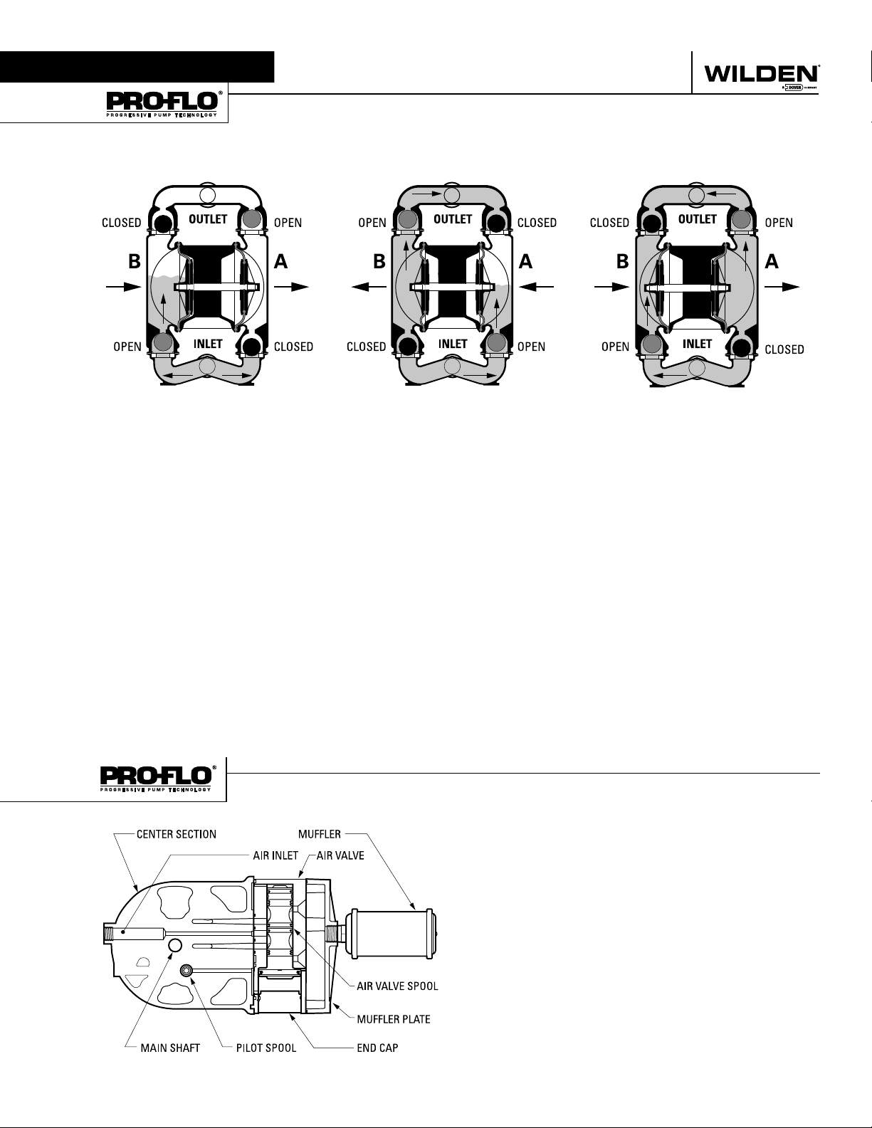
The Wilden diaphragm pump is an air-operated, positive displacement, self-priming pump. These drawings show fl ow pattern
through the pump upon its initial stroke. It is assumed the pump has no fl uid in it prior to its initial stroke.
FIGURE 1 The air valve dir ects pre ssurized
air to the back side of diaphragm A. The
compressed air is applied directly to the
liquid column separated by elastomeric
diaphragms. The diaphragm acts as
a separation membrane between the
compressed air and liquid, balancing the
load and removing mechanical stress
from the diaphragm. The compressed
air moves the diaphragm away from
the center of the pump. The opposite
diaphragm is pulled in by the shaf t
connected to the pressurized diaphragm.
Diaphragm B is on its suction stroke; air
behind the diaphragm has been forced
out to atmosphere through the exhaust
port of the pump. The movement of
diaphragm B toward the center of the
pump creates a vacuum within chamber B.
Atmospheric pressure forces fl uid into
the inlet manifold forcing the inlet valve
ball off its seat. Liquid is free to move
past the inlet valve ball and fi ll the liquid
chamber (see shaded area).
HOW IT WORKS—AIR DISTRIBUTION SYSTEM
FIGURE 2 When the pressurized diaphragm,
diaphra gm A, re aches t he limit of it s disc harge
stroke, the air valve redirects pressurized
air to the back side of diaphragm B. The
pressurized air forces diaphragm B away
from the center while pulling diaphragm A
to the center. Diaphragm B is now on its
discharge stroke. Diaphragm B forces the
inlet valve ball onto its seat due to the
hydraulic forces developed in the liquid
chamber and manifold of the pump. These
same hydraulic forces lift the discharge
valve ball off its seat, while the opposite
discharge valve ball is forced onto its seat,
forcing fl uid to fl ow through the pump
discharge. The movement of diaphragm A
toward the center of the pump creates a
vacuum within liquid chamber A. Atmospheric pressure forces fl uid into the inlet
manifold of the pump. The inlet valve ball
is forced off its seat allowing the fl uid being
pumped to fi ll the liquid chamber.
FIGURE 3 At completion of the stroke,
the air valve again redirects air to the
back side of diaphragm A, which star ts
diaphragm B on its exhaust stroke. As
the pump reaches its original starting
point, each diaphragm has gone through
one exhaust and one discharge stroke.
This constitutes one complete pumping
cycle. The pump may take several cycles
to completely prime depending on the
conditions of the application.
The Pro -Flo
moving parts : the air valve spool and the pilot spool. The heart of
the system is the air valve spool and air valve. This valve design
incorporates an unbalanced spool. The smaller end of the spool
is pressurized continuously, while the large end is alternately
pressurized then exhausted to move the spool. The spool directs
pressurized air to one air chamber while exhausting the other.
The air causes the main shaft/diaphragm assembly to shift to
one side — discharging liquid on that side and pulling liquid in
on the other side. When the shaft reaches the end of its stroke,
the inner piston actuates the pilot spool, which pressurizes and
exhausts the large end of the air valve spool. The repositioning
of the air valve spool routes the air to the other air chamber.
WIL-11250-E-03 3 WILDEN PUMP & ENGINEERING, LLC
®
patented air distribution system incorporates two
Section 4
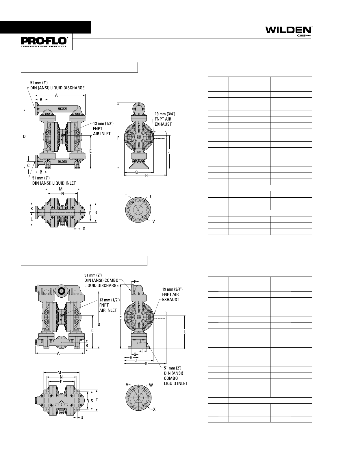
DIMENSIONAL DRAWINGS
P800 Plastic Side-Ported
DIMENSIONS
ITEM METRIC (mm) STANDARD (inch)
A 605 23.8
B 150 5.9
C 91 3.6
D 729 28.7
E 406 16.0
F 805 31.7
G 353 13.9
H 508 20.0
J 406 16.0
K 84 3.3
L 122 4.8
M 424 16.7
N 361 14.2
P 208 8.2
R 234 9.2
S 15 0.6
DIN FLANGE
T 125 DIA. 4.9 DIA.
U 165 DIA. 6.5 DIA.
V 18 DIA. 0.7 DIA.
ANSI FLANGE
T 122 DIA. 4.8 DIA.
U 152 DIA. 6.0 DIA.
V 20 DIA. 0.8 DIA.
P800 Plastic Center-Ported
DIMENSIONS
ITEM METRIC (mm) STANDARD (inch)
A 584 23.0
B 76 3.0
C 396 15.6
D 688 27.1
E 765 30.1
F 89 3.5
G 91 3.6
H 175 6.9
J 353 13.9
K 508 20.0
L 399 15.7
M 424 16.7
N 361 14.2
P 307 12.1
R 208 8.2
S 229 9.0
T 254 10.0
U 15 0.6
DIN / ANSI COMBO
V
W
X
152 DIA. 6.0 DIA.
122 DIA. 4.8 DIA.
20 DIA. 0.8 DIA.
WILDEN PUMP & ENGINEERING, LLC 4 WIL-11250-E-03
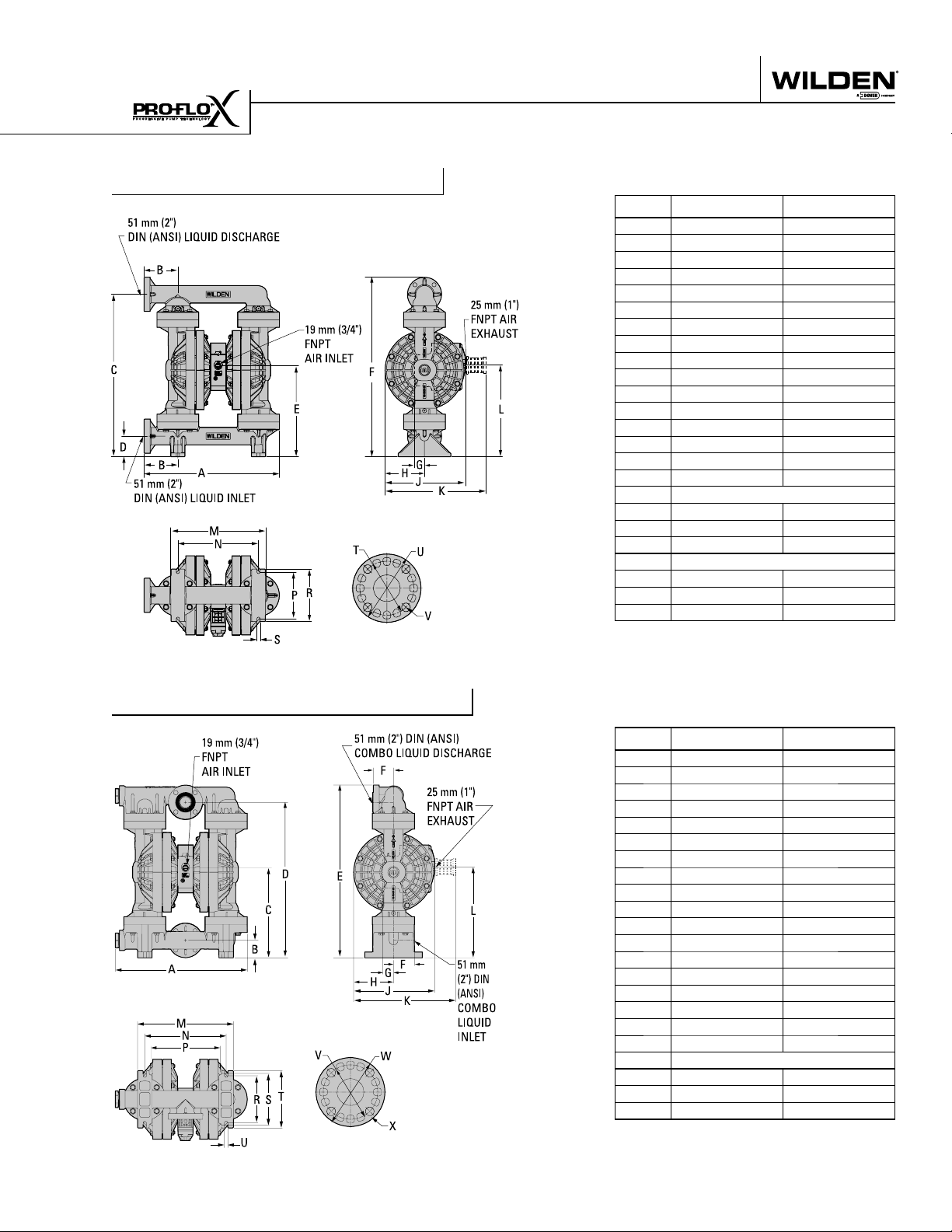
DIMENSIONAL DRAWING
PX800 Plastic Side-Ported
DIMENSIONS
ITEM METRIC (mm) STANDARD (inch)
A 605 23.8
B 150 5.9
C 729 28.7
D 91 3.6
E 406 16.0
F 805 31.7
G 48 1.9
H 178 7.0
J 356 14.0
K 452 17.8
L 414 16.3
M 424 16.7
N 361 14.2
P 208 8.2
R 234 9.2
S 15 0.6
DIN FLANGE
T 125 DIA. 4.9 DIA.
U 165 DIA. 6.5 DIA.
V 18 DIA. .7 DIA.
ANSI FLANGE
T 122 DIA. 4.8 DIA.
U 154 DIA. 6.0 DIA.
V 20 DIA. .8 DIA.
PX800 Plastic Center-Ported
DIMENSIONS
ITEM METRIC (mm) STANDARD (inch)
A 584 23.0
B 76 3.0
C 396 15.6
D 688 27.1
E 765 30.1
F 89 3.5
G 48 1.9
H 178 7.0
J 356 14.0
K 452 17.8
L 404 15.9
M 424 16.7
N 361 14.2
P 307 12.1
R 208 8.2
S 229 9.0
T 254 10.0
U 15 0.6
DIN / ANSI COMBO
V 152 DIA. 6.0 DIA.
W 122 DIA. 4.8 DIA.
X 20 DIA. .8 DIA.
WIL-11250-E-03 5 WILDEN PUMP & ENGINEERING, LLC
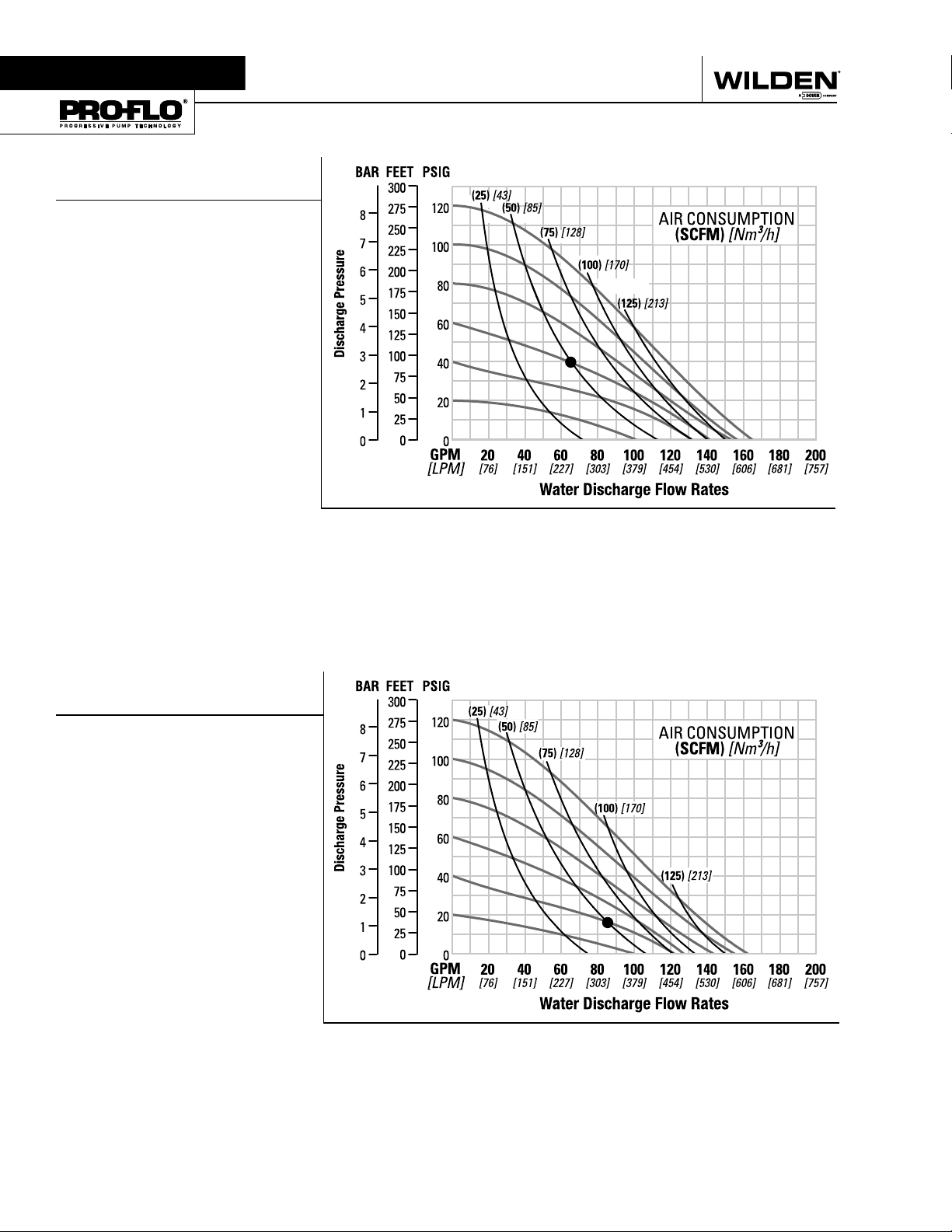
Section 5A
PERFORMANCE
P800 PLASTIC
RUBBER-FITTED
Height ..................................805 mm (31.7")
Width .................................. 605 mm (23.8")
Depth .................................. 353 mm (13.9")
Est. Ship Weight
Polypropylene 32 kg (70 lbs)
PVDF 45 kg (99 lbs)
Air Inlet ....................................13 mm (1⁄2")
Inlet ............................................ 51 mm (2")
Outlet ......................................... 51 mm (2")
Suction Lift ..................... 6.23 m Dry (20.4')
8.65 m Wet (28.4')
Displacement/Stroke 2.75 l (0.727 gal.)
Max. Flow Rate ............ 624 lpm (165 gpm)
Max. Size Solids .....................6.4 mm (1⁄4")
1
Displacement per stroke was calculated at
4.8 Bar (70 psig) air inlet pressure against
a 2 bar (30 psig) head pressure.
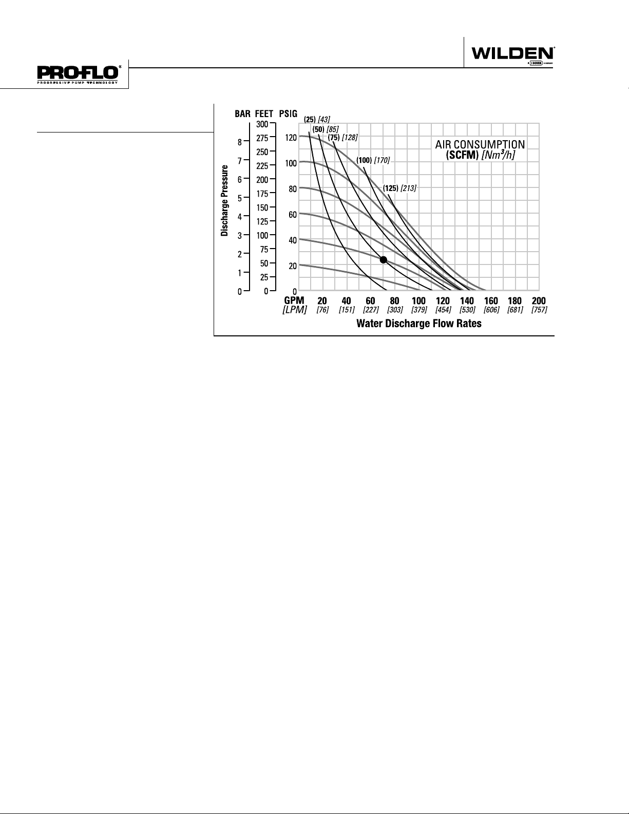
Example: To pump 246 lpm (65 gpm)
against a discharge head pressure of 2.8
Bar (40 psig) requires 4.1 bar (60 psig) and
85 Nm3/h (50 scfm) air consumption. (See
dot on chart.)
Caution: Do not exceed 8.6 bar (125 psig)
air supply pressure.
1
Flow rates indicated on chart were determined by pumping water.
For optimum life and performance, pumps should be specifi ed so that daily operation
parameters will fall in the center of the pump performance curve.
P800 PLASTIC
TPE-FITTED
Height ..................................805 mm (31.7")
Width .................................. 605 mm (23.8")
Depth .................................. 353 mm (13.9")
Est. Ship Weight
Polypropylene 32 kg (70 lbs)
PVDF 45 kg (99 lbs)
Air Inlet ....................................13 mm (1⁄2")
Inlet ............................................ 51 mm (2")
Outlet ......................................... 51 mm (2")
Suction Lift ................... 5.54 m Dry (18.16')
5.19 m Wet (17.0')
Displacement/Stroke .... 2.78 l (0.735 gal.)
Max. Flow Rate ............ 615 lpm (162 gpm)
Max. Size Solids .....................6.4 mm (1⁄4")
1
Displacement per stroke was calculated at
4.8 bar (70 psig) air inlet pressure against a
2 bar (30 psig) head pressure.
Example: To pump 321.8 lpm (85 gpm)
against a discharge head pressure of
1.2 bar (17 psig) requires 2.8 bar (40 psig)
and 85 Nm3/h (50 scfm) air consumption.
(See dot on chart.)
Caution: Do not exceed 8.6 bar (125 psig)
air supply pressure.
1
Flow rates indicated on chart were determined by pumping water.
For optimum life and performance, pumps should be specifi ed so that daily operation
parameters will fall in the center of the pump performance curve.
WILDEN PUMP & ENGINEERING, LLC 6 WIL-11250-E-03
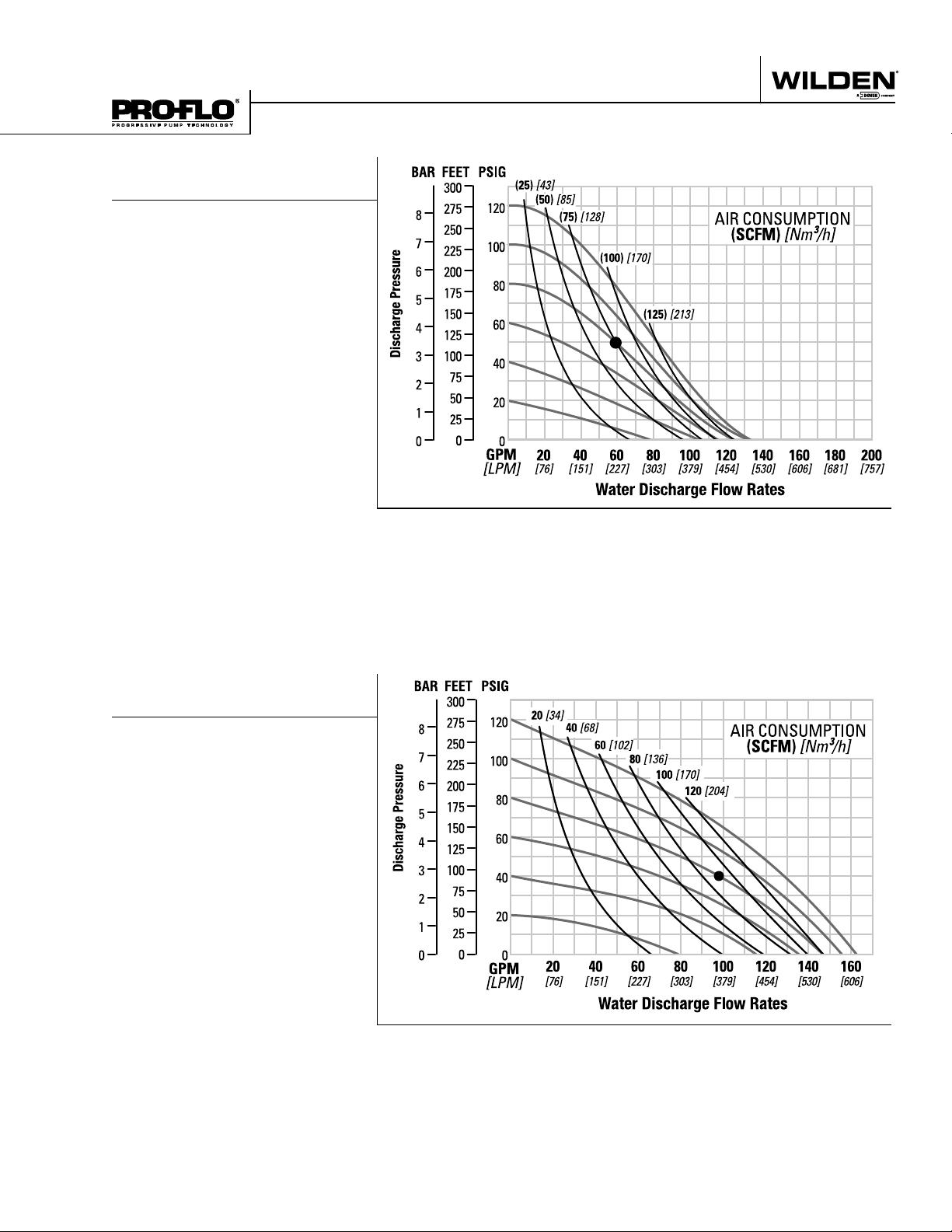
PERFORMANCE
P800 PLASTIC
REDUCED STROKE PTFE-FITTED
Height ..................................805 mm (31.7")
Width .................................. 605 mm (23.8")
Depth .................................. 353 mm (13.9")
Est. Ship Weight
Polypropylene 32 kg (70 lbs)
PVDF 45 kg (99 lbs)
Air Inlet ....................................13 mm (1⁄2")
Inlet ............................................ 51 mm (2")
Outlet ......................................... 51 mm (2")
Suction Lift ................... 4.15 m Dry (13.62')
8.65 m Wet (28.4')
Displacement/Stroke .... 1.73 l (0.457 gal.)
Max. Flow Rate ............ 504 lpm (133 gpm)
Max. Size Solids .....................6.4 mm (1⁄4")
1
Displacement per stroke was calculated at
4.8 bar (70 psig) air inlet pressure against a
2 bar (30 psig) head pressure.
Example: To pump 219.6 lpm (58 gpm)
against a discharge head pressure of 3.4
Bar (50 psig) requires 5.5 bar (80 psig) and
128 Nm3/h (75 scfm) air consumption. (See
dot on chart.)
Caution: Do not exceed 8.6 bar (125 psig)
air supply pressure.
1
Flow rates indicated on chart were determined by pumping water.
For optimum life and performance, pumps should be specifi ed so that daily operation
parameters will fall in the center of the pump performance curve.
P800 PLASTIC
FULL STROKE PTFE-FITTED
Height ................................. 804 mm (31.7”)
Width ..................................604 mm (23.8”)
Depth ..................................353 mm (13.9”)
Ship Weight . Polypropylene 32 kg (70 lbs.)
PVDF 45 kg (99 lbs.)
Air Inlet ...................................13 mm (1/2”)
Inlet ............................................51 mm (2”)
Outlet .........................................51 mm (2”)
Suction Lift ........................ 5.9m Dry (19.5’)
9.0 m Wet (29.5’)
Disp. Per Stroke ................. 2.5 l (0.67 gal.)
Max. Flow Rate ............ 615 lpm (162 gpm)
Max. Size Solids .................... 6.4 mm (1/4”)
1
Displacement per stroke was calculated at
4.8 bar (70 psig) air inlet pressure against a
2.1 bar (30 psig)head pressure.
Example: To pump 98 GPM against a
discharge head of 40 psigrequires 80 psig
and 92 scfm air consumption.
Caution: Do not exceed 8.6 bar (125 psig)
air supply pressure.
1
20 [34]
40 [68]
60 [102]
80 [136]
100 [170]
120 [204]
20 40 60 80 100 120 140 160
[76] [151] [227] [303] [379] [454] [530] [606]
Flow rates indicated on chart were determined by pumping water.
For optimum life and performance, pumps should be specifi ed so that daily operation
parameters will fall in the center of the pump performance curve.
WIL-11250-E-03 7 WILDEN PUMP & ENGINEERING, LLC
PERFORMANCE
P800 PLASTIC
ULTRA-FLEX™-FITTED
Height ..................................805 mm (31.7")
Width .................................. 605 mm (23.8")
Depth .................................. 353 mm (13.9")
Est. Ship Weight
Polypropylene 32 kg (70 lbs)
PVDF 45 kg (99 lbs)
Air Inlet ....................................13 mm (1⁄2")
Inlet ............................................ 51 mm (2")
Outlet ......................................... 51 mm (2")
Suction Lift ................... 4.84 m Dry (15.89')
8.65 m Wet (28.4')
Displacement/Stroke .... 1.73 l (0.457 gal.)
Max. Flow Rate ............ 588 lpm (155 gpm)
Max. Size Solids .....................6.4 mm (1⁄4")
1
Displacement per stroke was calculated at
4.8 bar (70 psig) air inlet pressure against a
2 bar (30 psig) head pressure.
Example: To pump 265 lpm (70 gpm)
against a discharge head pressure of
1.7 bar (24 psig) requires 2.8 bar (40 psig)
and 85 Nm3/h (50 scfm) air consumption.
(See dot on chart.)
Caution: Do not exceed 8.6 bar (125 psig)
air supply pressure.
1
Flow rates indicated on chart were determined by pumping water.
For optimum life and performance, pumps should be specifi ed so that daily operation
parameters will fall in the center of the pump performance curve.
WILDEN PUMP & ENGINEERING, LLC 8 WIL-11250-E-03
Section 5A
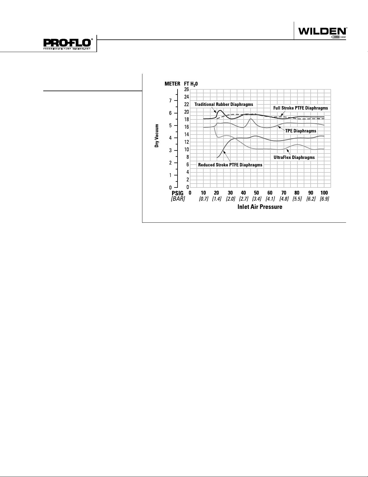
SUCTION LIFT CURVE
P800 PLASTIC
SUCTION LIFT CAPABILITY
WIL-11250-E-03 9 WILDEN PUMP & ENGINEERING, LLC

NOTES
PX800
P L A S T I C
PX800 PERFORMANCE
WIL-11250-E-03 11 WILDEN PUMP & ENGINEERING, LLC
Section 5B
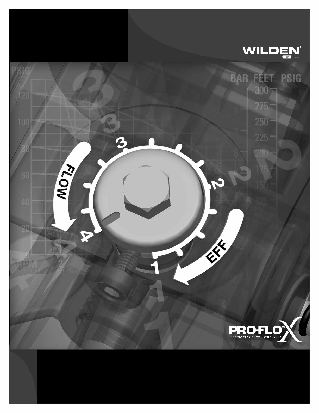
Pro-Flo X
The Pro-Flo X™ air distribution system with the
revolutionary Effi ciency Management System (EMS)
offers fl exibility never before seen in the world of
AODD pumps. The
patent-pending EMS
is simple and easy
to use. With the
turn of an integrated
TM
Operating Principal
control dial, the operator can select the optimal
balance of fl ow and effi ciency that best meets the
application needs. Pro-Flo X™ provides higher
performance, lower
operational costs
and fl exibility that
exceeds previous
industry standards.
AIR CONSUMPTION
$
$
$
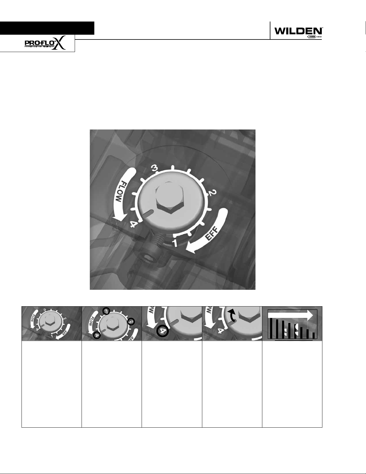
Turning the dial
changes the
relationship
between air inlet
and exhaust
porting.
WILDEN PUMP & ENGINEERING, LLC 12 PX800 Performance
Each dial setting
represents an
entirely different
fl ow curve
Pro-Flo X™ pumps
are shipped from
the factory on
setting 4, which
is the highest
fl ow rate setting
possible
Moving the dial
from setting 4
causes a decrease
in fl ow and an even
greater decrease in
air consumption.
When the air
consumption
decreases more
than the fl ow
rate, effi ciency
is improved and
operating costs
are reduced.
Example 1
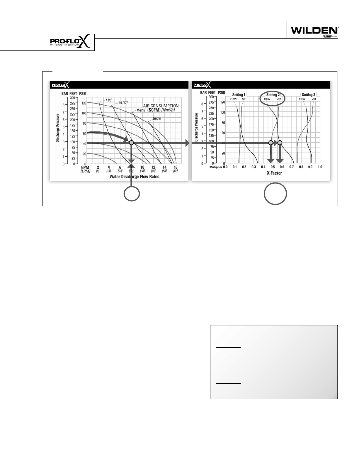
HOW TO USE THIS EMS CURVE
SETTING 4 PERFORMANCE CURVE
Figure 1 Figure 2
Example data point = Example data point =
This is an example showing how to determine fl ow rate and
air consumption for your Pro-Flo X™ pump using the Effi ciency Management System (EMS) curve and the performance
curve. For this example we will be using 4.1 bar (60 psig) inlet
air pressure and 2.8 bar (40 psig) discharge pressure and EMS
setting 2.
Step 1:
Identifying performance at setting 4. Locate
the curve that represents the fl ow rate of the
pump with 4.1 bar (60 psig) air inlet pressure.
Mark the point where this curve crosses the
horizontal line representing 2.8 bar (40 psig)
discharge pressure. (Figure 1). After locating
your performance point on the fl ow curve,
draw a vertical line downward until reaching
the bottom scale on the chart. Identify the fl ow
rate (in this case, 8.2 gpm). Observe location
of performance point relative to air consumption curves and approximate air consumption
value (in this case, 9.8 scfm).
8.2
GPM
curve, draw vertical lines downward until
reaching the bottom scale on the chart. This
identifi es the fl ow X Factor (in this case, 0.58)
and air X Factor (in this case, 0.48).
Step 3:
Calculating performance for specific EMS
setting. Multiply the fl ow rate (8.2 gpm)
obtained in Step 1 by the fl ow X Factor multiplier (0.58) in Step 2 to determine the fl ow rate
at EMS setting 2. Multiply the air consumption (9.8 scfm) obtained in Step 1 by the air
X Factor multiplier (0.48) in Step 2 to determine the air consumption at EMS setting 2
(Figure 3).
gpm
8.2
.58
gpm
4.8
0.58
0.48
(fl ow rate for Setting 4)
(Flow X Factor setting 2)
(Flow rate for setting 2)
EMS CURVE
fl ow multiplier
air multiplier
Step 2:
Determining flow and air X Factors. Locate
your discharge pressure (40 psig) on the vertical axis of the EMS curve (Figure 2). Follow
along the 2.8 bar (40 psig) horizontal line until
intersecting both fl ow and air curves for your
desired EMS setting (in this case, setting 2).
Mark the points where the EMS curves intersect the horizontal discharge pressure line.
After locating your EMS points on the EMS
PX800 Performance 13 WILDEN PUMP & ENGINEERING, LLC
Figure 3
The fl ow rate and air consumption at Setting
2 are found to be 18.2 lpm (4.8 gpm) and 7.9
Nm3/h (4.7 scfm) respectively.
9.8
.48
4.7
scfm
(air consumption for setting 4)
(Air X Factor setting 2)
scfm
(air consumption for setting 2)
 Loading...