

Page 1

EOM
Engineering
Operation &
Maintenance
PX8
Sani o™ Hygienic Series
Metal Pumps
Where Innovation Flows
www.wildenpump.com
WIL-12310-E- 04
TO REPL ACE W IL-12310-E -0 3
Page 2
TABLE OF CONTENTS
SECTION 1 CAUTIONS—READ FIRST! . . . . . . . . . . . . . . . . . . . . . . . . . . . . . . . . . . . . . . . . . . . . . .1
SECTION 2 WILDEN PUMP DESIGNATION SYSTEM . . . . . . . . . . . . . . . . . . . . . . . . . . . . . . . . .2
SECTION 3 HOW IT WORKS—PUMP & AIR DISTRIBUTION SYSTEM . . . . . . . . . . . . . . . . 3
SECTION 4 DIMENSIONAL DRAWINGS . . . . . . . . . . . . . . . . . . . . . . . . . . . . . . . . . . . . . . . . . . . . .4
SECTION 5 PERFORMANCE
A. PX8 Performance Curves . . . . . . . . . . . . . . . . . . . . . . . . . . . . . . . . . . . . . . . . . . . . . . . .7
Operating Principle . . . . . . . . . . . . . . . . . . . . . . . . . . . . . . . . . . . . . . . . . . . . . . . . . . . . .8
How to Use this Curve . . . . . . . . . . . . . . . . . . . . . . . . . . . . . . . . . . . . . . . . . . . . . . . . . . .9
Rubber-Fitted . . . . . . . . . . . . . . . . . . . . . . . . . . . . . . . . . . . . . . . . . . . . . . . . . . . . . . . 12
TPE-Fitted . . . . . . . . . . . . . . . . . . . . . . . . . . . . . . . . . . . . . . . . . . . . . . . . . . . . . . . . . .13
Full Stroke PTFE-Fitted . . . . . . . . . . . . . . . . . . . . . . . . . . . . . . . . . . . . . . . . . . . . . . . 14
Full Stroke SIPD-Fitted . . . . . . . . . . . . . . . . . . . . . . . . . . . . . . . . . . . . . . . . . . . . . . .15
Reduced Stroke PTFE-Fitted . . . . . . . . . . . . . . . . . . . . . . . . . . . . . . . . . . . . . . . . . . .16
Reduced Stroke SIPD-Fitted . . . . . . . . . . . . . . . . . . . . . . . . . . . . . . . . . . . . . . . . . . . 17
Reduced Stroke Ultra-Flex™-Fitted . . . . . . . . . . . . . . . . . . . . . . . . . . . . . . . . . . . . . 18
B. Suction Lift Curves . . . . . . . . . . . . . . . . . . . . . . . . . . . . . . . . . . . . . . . . . . . . . . . . . . . .19
SECTION 6 SUGGESTED INSTALLATION, OPERATION & TROUBLESHOOTING . . . . . . . 21
SECTION 7 ASSEMBLY / DISASSEMBLY . . . . . . . . . . . . . . . . . . . . . . . . . . . . . . . . . . . . . . . . . . .24
SECTION 8 CLEANING - CIP . . . . . . . . . . . . . . . . . . . . . . . . . . . . . . . . . . . . . . . . . . . . . . . . . . . . . . .33
SECTION 9 EXPLODED VIEW & PARTS LISTING
PX8 Saniflo™ HS . . . . . . . . . . . . . . . . . . . . . . . . . . . . . . . . . . . . . . . . . . . . . . . . . . . . . . . .34
SECTION 10 ELASTOMER OPTIONS . . . . . . . . . . . . . . . . . . . . . . . . . . . . . . . . . . . . . . . . . . . . . . .37
Page 3
Section 1
CAUTIONS—READ FIRST!
CAUTION: Do not apply compressed air to the
exhaust port — pump will not function.
CAUTION: Do not over-lubricate air supply —
excess lubrication will reduce pump performance.
Pump is pre-lubed.
TEMPERATURE LIMITS:
Neoprene –17.7°C to 93.3°C 0°F to 200°F
Buna-N –12.2°C to 82.2°C 10°F to 180°F
Nordel
Viton® –40°C to 176.7°C –40°F to 350°F
Sanifl ex™ –28.9°C to 104.4°C –20°F to 220°F
Polytetrafl uoroethylene (PTFE)
4.4°C to 104.4°C 40°F to 220°F
Polyurethane –12.2°C to 65.6°C 10°F to 150°F
Tetra-Flex™ PTFE w/Neoprene Backed
4.4°C to 107.2°C 40°F to 225°F
Tetra-Flex™ PTFE w/Nordel® Backed
-10°C to 137°C 14°F to 280°F
Wil-Flex™ (Santoprene®)
-40°C to 107.2°C -40°F to 225°F
NOTE: Not all materials are available for all
models. Refer to Section 2 for material options
for your pump.
®
–51.1°C to 137.8°C –60°F to 280°F
CAUTION: Do not exceed 82°C (180°F) air inlet
temperature for Pro-Flo X™ models.
CAUTION: Pumps should be thoroughly fl ushed
before installing into process lines. FDA and
USDA approved pumps should be cleaned and/
or sanitized before being used.
CAUTION: Always wear safety glasses when
operating pump. If diaphragm rupture occurs,
material being pumped may be forced out air
exhaust.
CAUTION: Before any maintenance or repair is
attempted, the compressed air line to the pump
should be disconnected and all air pressure
allowed to bleed from pump. Disconnect all
intake, discharge and air lines. Drain the pump
by turning it upside down and allowing any fl uid
to fl ow into a suitable container.
CAUTION: Blow out air line for 10 to 20 seconds
before attaching to pump to make sure all pipeline
debris is clear. Use an in-line air fi lter. A 5µ (micron)
air fi lter is recommended.
CAUTION: When choosing pump materials, be
sure to check the temperature limits for all wetted
components. Example: Viton® has a maximum
limit of 176.7°C (350°F) but polypropylene has a
maximum limit of only 79°C (175°F).
CAUTION: Maximum temperature limits are
based upon mechanical stress only. Certain
chemicals will signifi cantly reduce maximum
safe operating temperatures. Consult Chemical
Resistance Guide (E4) for chemical compatibility
and temperature limits.
WARNING: Prevention of static sparking — If
static sparking occurs, fi re or explosion could
result. Pump, valves, and containers must be
grounded to a proper grounding point when
handling fl ammable fl uids and whenever
discharge of static electricity is a hazard.
CAUTION: Do not exceed 8.6 bar (125 psig) air
supply pressure.
CAUTION: The process fl uid and cleaning fl uids
must be chemically compatible with all wetted
pump components. Consult Chemical Resistance
Guide (E4).
NOTE: When installing PTFE diaphragms, it is
important to tighten outer pistons simultaneously
(t urning in opposite directions ) to ensure tight fi t.
(See torque specifi cations in Section 7.)
NOTE: Cast Iron PTFE-fi tted pumps come
standard from the factory with expanded PTFE
gaskets installed in the diaphragm bead of the
liquid chamber. PTFE gaskets cannot be re-used.
Consult PS-TG for installation instructions during
reassembly.
NOTE: Before starting disassembly, mark a line
from each liquid chamber to its corresponding air
chamber. This line will assist in proper alignment
during reassembly.
CAUTION: Pumps are available in both
submersible and non-submersible options. Do
not use non-submersible Pro-Flo X™ models in
submersible applications.
CAUTION: Tighten all hardware prior to installation.
WIL-12310-E-04 1 WILDEN PUMP & ENGINEERING, LLC
Page 4
Section 2
WILDEN PUMP DESIGNATION SYSTEM
PX8 SANIFLO
™
HYGIENIC SERIES
51 mm (2") Pump
Maximum Flow Rate:
587 lpm (155 gpm)
LEGEND
PX8 / XXXXX / XXX / XX/ XX/ XXXX
MODEL
MATERIAL CODES
MODEL
PX8 = 51 mm (2")
XPX8 = 51 mm (2") ATEX
WETTED PARTS/
OUTER PISTON
SS = 316L STAINLESS STEEL
SZ = 316L STAINLESS STEEL/
NO PISTON
CENTER BLOCK
N = NICKEL PLATED ALUMINUM
S = 316 STAINLESS STEEL
AIR CHAMBERS
N = NICKEL PLATED ALUMINUM
S = 316 STAINLESS STEEL
AIR VALVE
N = NICKEL PLATED ALUMINUM
S = 316 STAINLESS STEEL
DIAPHRAGMS
VALVE OPTION
AIR VALVE
AIR CHAMBER
CENTER SECTION
WETTED PARTS & OUTER PIS TON
DIAPHRAGMS
BNU = ULTRA-FLEX™ BUNA
EPU = ULTRA-FLEX™ EPDM
FBS = SANITARY BUNA
(two yellow dots)
FES = SANITARY EPDM
(two blue dots)
FSS = SANIFLEX™
FWL = FULL STROKE SANITARY
WIL-FLEX™ IPD
1
1,3,4
FWS = SANITARY WIL-FLEX™
LEL = PTFE-EPDM BACKED
LAMINATE IPD
1,2,3,4,5
TEU = PTFE w/EPDM BACKUP
TSS = FULL STROKE PTFE
w/SANIFLEX™ BACK-UP
TSU = PTFE w/SANIFLEX™
BACK-UP
1,2,5
TWS = FULL STROKE PTFE
w/WIL-FLEX™ BACK-UP
GASKETS
SPECIALTY
CODE
(if applicable)
VALVE BALLS, FLAP VALVES,
1,5
MUSHROOM CHECK
1,5
1
1
FB = SANITARY BUNA
(red dot)
FE = SANITARY EPDM
(green dot)
FS = SANIFLEX™
FW = SANITARY WIL-FLEX™
SF = STAINLESS STEEL FLAP
TF = PTFE
1
TM = PTFE MUSHROOM
CHECK
1,2,5
MANIFOLD GASKET
FB = SANITARY BUNA-N
1,2
(red dot)
1,2,3,4
1,2
FE = SANITARY EPDM
(green dot)
FV = SANITARY VITON®
1,2
(one white/one
yellow dots)
TF = PTFE
1,2,3,4,5
1,3,4
1,3,4
1,3,4
1,3,4
1,5
1,3,4
1,3,4
1, 3, 4
NOTE:
1. Meets Requirements of FDA CFR21.177
2. Meets Requirements of USPClass VI
3. Required for EHEDG Certification
4. Required for 3-A Certification
5. Stainless flap valve not available with reduced stroke PTFE, reduced
stroke Ultra-Flex
TM
or reduced stroke Laminate IP diaphragms
SPECIALTY CODES
0770 SaniFlo HS
0771 SaniFlo HS, w /Swivel Stand
0772 SaniFlo HS, Wil-Gard 110V
0773 SaniFlo HS, Wil-Gard 22 0V
0774 HS, Wil-Gard 110V, w/Swivel Stand
0775 SaniFlo HS, Wil-Gard 220V, w/Swivel Stand
0778 SaniFlo HS, DIN Connection
0779 HS, w/Swivel Stand DIN Connection
0780 SaniFlo HS, Wil-Gard 110V DIN Connection
NOTE: MOST EL ASTOMERIC MATERIA LS USE COLORED DOTS FOR IDENTIFICATION.
®
Viton
is a registered trademark of DuPont Dow Elas tomers.
WILDEN PUMP & ENGINEERING, LLC 2 WIL-12310-E-04
0781 SaniFlo HS, Wil-Gard 22 0V DIN Connection
0782 SaniFlo HS, Wil-Gard 110V, w/Swivel St and DIN Connection
0783 SaniFlo HS, Wil-Gard 22 0V, w/Swivel S tand DIN Connection
0784 SaniFlo HS, SMS Connection
0785 SaniFlo HS, w/Swivel Stand SMS Connection
0786 SaniFlo HS, Wil-Gard 110V SMS Connection
0787 SaniFlo HS, Wil-Gard 22 0V SMS Connection
0788 SaniFlo HS, Wil-Gard 110V, w/Swivel St and SMS Connection
0789 SaniFlo HS, Wil-Gard 22 0V, w/Swivel S tand SMS Connection
Page 5
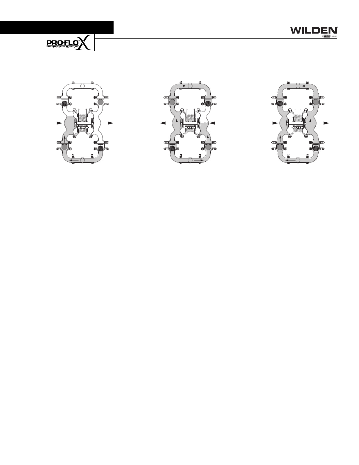
Section 3
The Wilden diaphragm pump is an air-operated, positive displacement, self-priming pump. These drawings show fl ow pattern
through the pump upon its initial stroke. It is assumed the pump has no fl uid in it prior to its initial stroke.
CLOSED
OUTLET
BA
INLET
FIGURE 1 The air valve dir ects pre ssurized
air to the back side of diaphragm A. The
compressed air is applied directly to the
liquid column separated by elastomeric
diaphragms. The diaphragm acts as
a separation membrane between the
compressed air and liquid, balancing the
load and removing mechanical stress
from the diaphragm. The compressed
air moves the diaphragm away from
the center of the pump. The opposite
diaphragm is pulled in by the shaft
connected to the pressurized diaphragm.
Diaphragm B is on its suction stroke; air
behind the diaphragm has been forced
out to atmosphere through the exhaust
port of the pump. The movement of
diaphragm B toward the center of the
pump creates a vacuum within chamber B.
Atmospheric pressure forces fl uid into
the inlet manifold forcing the inlet valve
ball off its seat. Liquid is free to move
past the inlet valve ball and fi ll the liquid
chamber (see shaded area).
HOW IT WORKS—PUMP
OPEN
OPEN
OUTLET
BA
CLOSEDOPEN
FIGURE 2 When the pressurized diaphragm,
diaphra gm A, re aches t he limit of it s disc harge
stroke, the air valve redirects pressurized
air to the back side of diaphragm B. T he
pressurized air forces diaphragm B away
from the center while pulling diaphragm A
to the center. Diaphragm B is now on its
discharge stroke. Diaphragm B forces the
inlet valve ball onto its seat due to the
hydraulic forces developed in the liquid
chamber and manifold of the pump. These
same hydraulic forces lift the discharge
valve ball off its seat, while the opposite
discharge valve ball is forced onto its seat,
forcing fl uid to fl ow through the pump
discharge. The movement of diaphragm A
toward the center of the pump creates a
vacuum within liquid chamber A. Atmospheric pressure forces fl uid into the inlet
manifold of the pump. The inlet valve ball
is forced off its seat allowing the fl uid being
pumped to fi ll the liquid chamber.
INLET
CLOSED
OPENCLOSED
CLOSED
OUTLET
OPEN
BA
INLET
FIGURE 3 At completion of the stroke,
the air valve again redirects air to the
back side of diaphragm A, which star ts
diaphragm B on its exhaust stroke. As
the pump reaches its original starting
point, each diaphragm has gone through
one exhaust and one discharge stroke.
This constitutes one complete pumping
cycle. The pump may take several cycles
to completely prime depending on the
conditions of the application.
CLOSEDOPEN
WIL-12310-E-04 3 WILDEN PUMP & ENGINEERING, LLC
Page 6
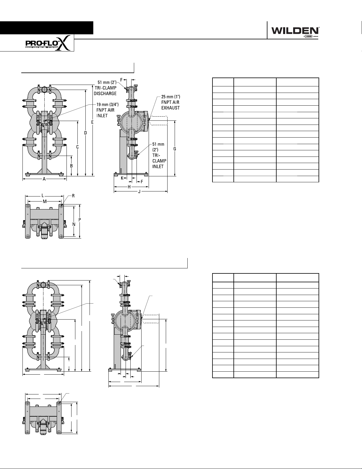
Section 4
DIMENSIONAL DRAWINGS
PX8 Saniflo™ HS Fixed
DIMENSIONS
ITEM METRIC (mm) STANDARD (inch)
A 460 18.1
B 213 8.4
C 577 22.7
D 902 35.5
E 955 37.6
F 51 2.0
G 579 22.8
H 363 14.3
J 559 22.0
K 46 1.8
L 401 15.8
M 351 13.8
N 318 12.5
P 356 14.0
R
ø10 ø0.4
Rev A
PX8 Saniflo™ HS Flap Valve Fixed
51 mm (2")
TRI-CLAMP
DISCHARGE
19 mm (3/4")
FNPT AIR
INLET
E
D
C
B
A
L
M
R
P
N
F
25 mm (1")
FNPT AIR
EXHAUST
51 mm
(2")
TRICLAMP
INLET
K
F
H
J
G
DIMENSIONS
ITEM METRIC (mm) STANDARD (inch)
A 460 18.1
B 160 6.3
C 577 22.7
D 955 37.6
E 1008 39.7
F 51 2.0
G 579 22.8
H 363 14.3
J 559 22.0
K 56 2.2
L 401 15.8
M 351 13.8
N 318 12.5
P 356 14.0
R
ø10 ø0.4
Rev A
WILDEN PUMP & ENGINEERING, LLC 4 WIL-12310-E-04
Page 7
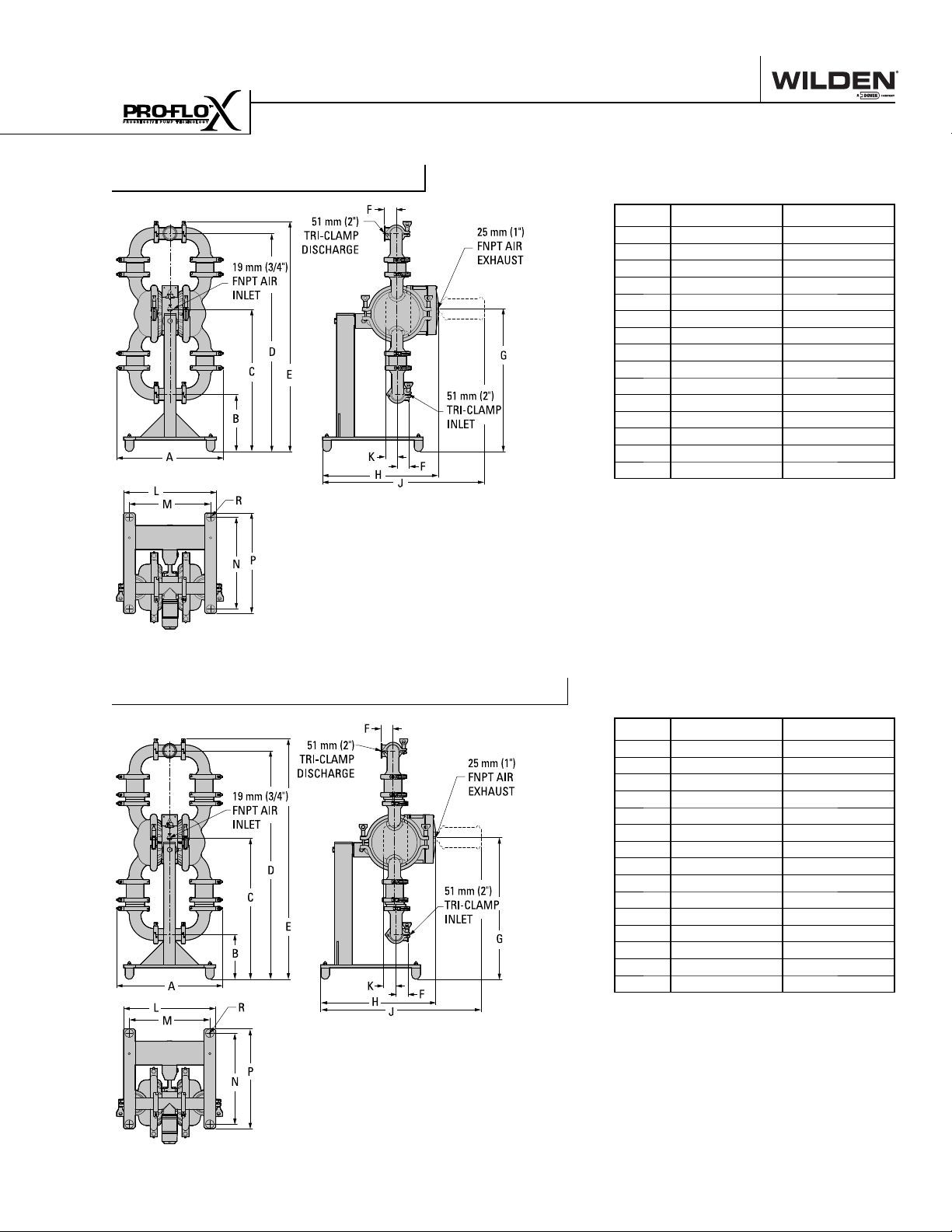
Section 4
DIMENSIONAL DRAWINGS
PX8 Saniflo™ HS Swivel
DIMENSIONS
ITEM METRIC (mm) STANDARD (inch)
A 460 18.1
B 247 9.7
C 612 24.1
D 938 36.9
E 989 38.9
F 51 2.0
G 615 24.2
H 498 19.6
J 693 27.3
K 46 1.8
L 401 15.8
M 351 13.8
N 394 15.5
P 432 17.0
R ø10 ø0.4
Rev B
PX8 Saniflo™ HS Flap Valve Swivel
DIMENSIONS
ITEM METRIC (mm) STANDARD (inch)
A 460 18.1
B 194 7.6
C 612 24.1
D 990 39.0
E 1042 41.0
F 51 2.0
G 615 24.2
H 498 19.6
J 693 27.3
K 56 2.2
L 401 15.8
M 351 13.8
N 394 15.5
P 432 17.0
R ø10 ø0.4
Rev B
WIL-12310-E-04 5 WILDEN PUMP & ENGINEERING, LLC
Page 8
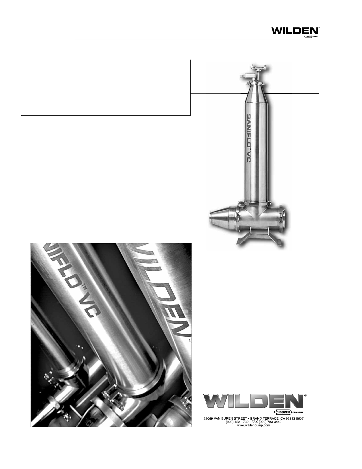
Pump Solids
Maximize Your Yield
Is your process limping along with a pump that wasn't
designed to transfer sanitary solids? Are your inspection,
cleaning, and maintenance costs too high? Are you looking
for a pump that is actually designed for your application?
Wilden has your answer. The Saniflo™ VC pump can trans-
fer your product without damage from bruising or shearing.
The pump is specifically designed to meet your performance
needs while minimizing cleaning and inspection time. Contact
us for a unique perspective and proven results. The Saniflo™
VC will handle any food product that you can dish out.
• 3 sizes available
• Solids passage to 152 mm (6")
• Stainless steel construction
• Only 2 moving parts
• Low liquid content requirement
• Complies with
USDA requirements
• Variable fl ow
• CE marked
• Low voltage directive by TÜV
• PED & machinery directive
WILDEN PUMP & ENGINEERING, LLC 6 WIL-12310-E-04
Page 9
PX8
SANIFLO
PX8 SANIFLO HS PERFORMANCE
Page 10
Section 5A
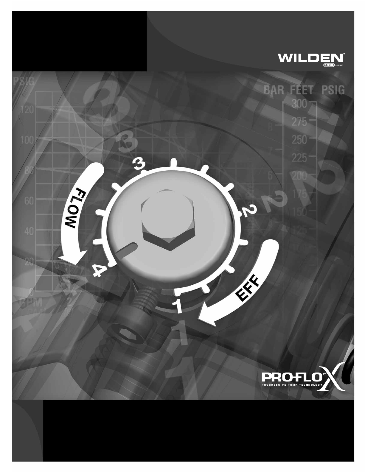
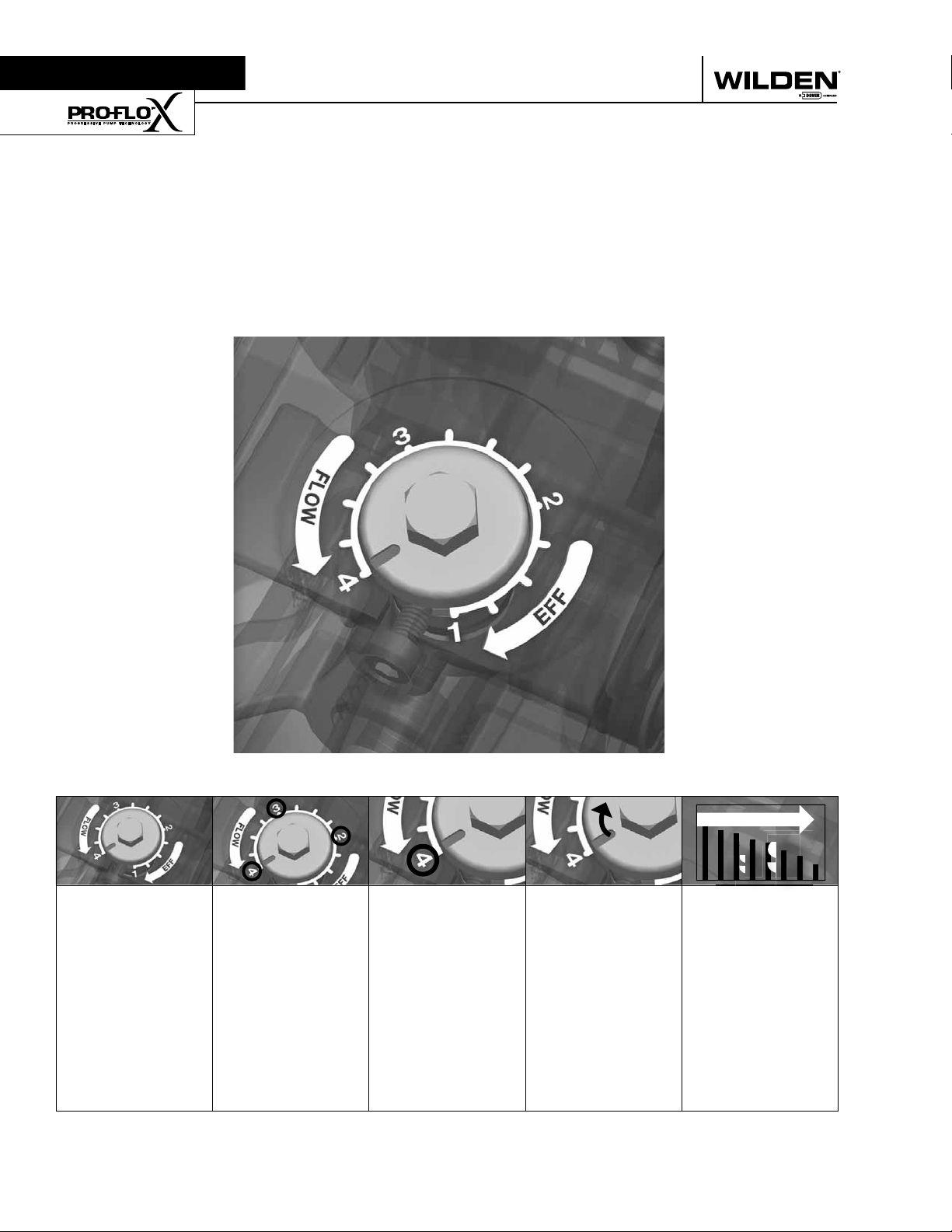
Pro-Flo X
The Pro-Flo X™ air distribution system with the
revolutionary Effi ciency Management System (EMS)
offers fl exibility never before seen in the world of
AODD pumps. The
patent-pending EMS
is simple and easy
to use. With the
turn of an integrated
TM
Operating Principle
control dial, the operator can select the optimal
balance of fl ow and effi ciency that best meets the
application needs. Pro-Flo X™ provides higher
performance, lower
operational costs
and fl exibility that
exceeds previous
industry standards.
AIR CONSUMPTION
$
$
$
Turning the dial
changes the
relationship
between air inlet
and exhaust
porting.
WILDEN PUMP & ENGINEERING, LLC 8 PX8 HS Performance
Each dial setting
represents an
entirely different
fl ow curve
Pro-Flo X™ pumps
are shipped from
the factory on
setting 4, which
is the highest
fl ow rate setting
possible
Moving the dial
from setting 4
causes a decrease
in fl ow and an even
greater decrease in
air consumption.
When the air
consumption
decreases more
than the fl ow
rate, effi ciency
is improved and
operating costs
are reduced.
Page 11
Example 1
HOW TO USE THIS EMS CURVE
SETTING 4 PERFORMANCE CURVE
Figure 1 Figure 2
Example data point = Example data point =
This is an example showing how to determine fl ow rate and
air consumption for your Pro-Flo X™ pump using the Effi ciency Management System (EMS) curve and the performance
curve. For this example we will be using 4.1 bar (60 psig) inlet
air pressure and 2.8 bar (40 psig) discharge pressure and EMS
setting 2.
Step 1:
Identifying performance at setting 4. Locate
the curve that represents the fl ow rate of the
pump with 4.1 bar (60 psig) air inlet pressure.
Mark the point where this curve crosses the
horizontal line representing 2.8 bar (40 psig)
discharge pressure. (Figure 1). After locating
your performance point on the fl ow curve,
draw a vertical line downward until reaching
the bottom scale on the chart. Identify the fl ow
rate (in this case, 8.2 gpm). Observe location
of performance point relative to air consumption curves and approximate air consumption
value (in this case, 9.8 scfm).
8.2
GPM
curve, draw vertical lines downward until
reaching the bottom scale on the chart. This
identifi es the fl ow X Factor (in this case, 0.58)
and air X Factor (in this case, 0.48).
Step 3:
Calculating performance for specific EMS
setting. Multiply the fl ow rate (8.2 gpm)
obtained in Step 1 by the fl ow X Factor multiplier (0.58) in Step 2 to determine the fl ow rate
at EMS setting 2. Multiply the air consumption (9.8 scfm) obtained in Step 1 by the air
X Factor multiplier (0.48) in Step 2 to determine the air consumption at EMS setting 2
(Figure 3).
8.2
gpm
.58
4.8
gpm
0.58
0.48
(fl ow rate for Setting 4)
(Flow X Factor setting 2)
(Flow rate for setting 2)
EMS CURVE
fl ow multiplier
air multiplier
Step 2:
Determining flow and air X Factors. Locate
your discharge pressure (40 psig) on the vertical axis of the EMS curve (Figure 2). Follow
along the 2.8 bar (40 psig) horizontal line until
intersecting both fl ow and air curves for your
desired EMS setting (in this case, setting 2).
Mark the points where the EMS curves intersect the horizontal discharge pressure line.
After locating your EMS points on the EMS
PX8 HS Performance 9 WILDEN PUMP & ENGINEERING, LLC
9.8
scfm
(air consumption for setting 4)
.48
4.7
Figure 3
The fl ow rate and air consumption at Setting
2 are found to be 18.2 lpm (4.8 gpm) and 7.9
Nm3/h (4.7 scfm) respectively.
(Air X Factor setting 2)
scfm
(air consumption for setting 2)
Page 12
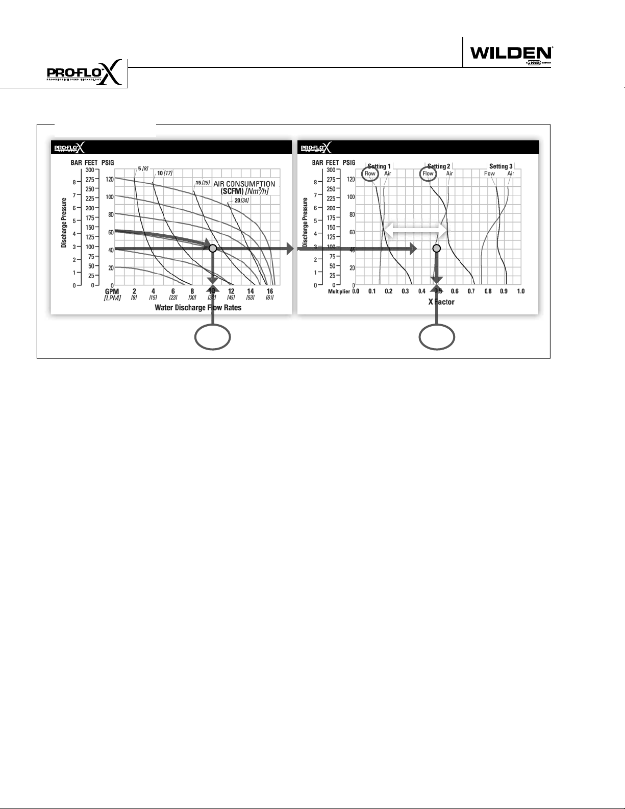
HOW TO USE THIS EMS CURVE
Example 2.1
SETTING 4 PERFORMANCE CURVE
Figure 4
Example data point =
This is an example showing how to determine the inlet air
pressure and the EMS setting for your Pro-Flo X™ pump to
optimize the pump for a specifi c application. For this example we will be using an application requirement of 18.9 lpm
(5 gpm) fl ow rate against 2.8 bar (40 psig) discharge pressure.
This example will illustrate how to calculate the air consumption that could be expected at this operational point.
10.2
gpm
DETERMINE EMS SETTING
Step 1
: Establish inlet air pressure. Higher air pres-
sures will typically allow the pump to run
more effi ciently, however, available plant air
pressure can vary greatly. If an operating
pressure of 6.9 bar (100 psig) is chosen when
EMS Flow
Settings 1 & 2
0.49
In our example it is 38.6 lpm (10.2 gpm). This
is the setting 4 fl ow rate. Observe the location of the performance point relative to air
consumption curves and approximate air
consumption value. In our example setting
4 air consumption is 24 Nm3/h (14 scfm).
See fi gure 4.
Step 3
: Determine flow X Factor. Divide the required
fl ow rate 18.9 lpm (5 gpm) by the setting 4 fl ow
rate 38.6 lpm (10.2 gpm) to determine the fl ow
X Factor for the application.
5
gpm / 10.2 gpm = 0.49 (flow X Factor)
EMS CURVE
Figure 5
fl ow multiplier
plant air frequently dips to 6.2 bar (90 psig)
Step 4
pump performance will vary. Choose an operating pressure that is within your compressed
air system's capabilities. For this example we
will choose 4.1 bar (60 psig).
: Determine EMS setting from the flow
X Factor. Plot the point representing the fl ow
X Factor (0.49) and the application discharge
pressure 2.8 bar (40 psig) on the EMS curve.
This is done by following the horizontal 2.8
Step 2
: Determine performance point at setting 4. For
this example an inlet air pressure of 4.1 bar
(60 psig) inlet air pressure has been chosen.
Locate the curve that represents the performance of the pump with 4.1 bar (60 psig) inlet
air pressure. Mark the point where this curve
crosses the horizontal line representing 2.8
bar (40 psig) discharge pressure. After locating this point on the fl ow curve, draw a vertical line downward until reaching the bottom
scale on the chart and identify the fl ow rate.
bar (40 psig) psig discharge pressure line until
it crosses the vertical 0.49 X Factor line. Typically, this point lies between two fl ow EMS
setting curves (in this case, the point lies between the fl ow curves for EMS setting 1 and
2). Observe the location of the point relative
to the two curves it lies between and approximate the EMS setting (fi gure 5). For more precise results you can mathematically interpolate between the two curves to determine the
optimal EMS setting.
For this example the EMS setting is 1.8.
WILDEN PUMP & ENGINEERING, LLC 10 PX8 HS Performance
Page 13
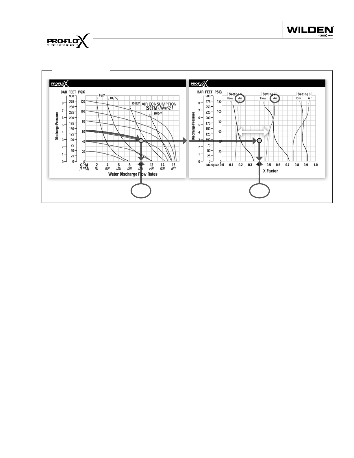
HOW TO USE THIS EMS CURVE
Example 2.2
SETTING 4 PERFORMANCE CURVE
Figure 6
Example data point =
10.2
gpm
Determine air consumption at a specific
EMS setting.
Step 1
: Determine air X Factor. In order to determine
the air X Factor, identify the two air EMS setting curves closest to the EMS setting established in example 2.1 (in this case, the point lies
between the air curves for EMS setting 1 and
2). The point representing your EMS setting
(1.8) must be approximated and plotted on the
EMS curve along the horizontal line representing your discharge pressure (in this case, 40
psig). This air point is different than the fl ow
point plotted in example 2.1. After estimating
(or interpolating) this point on the curve, draw
a vertical line downward until reaching the
bottom scale on the chart and identify the air
X Factor (fi gure 7).
EMS CURVE
EMS Air
Settings 1 & 2
Figure 7
Example data point =
Step 2
: Determine air consumption. Multiply your
setting 4 air consumption (14 scfm) value by
the air X Factor obtained above (0.40) to determine your actual air consumption.
1
4 scfm x 0.40 = 5.6 SCFM
In summary, for an application requiring 18.9 lpm
(5 gpm) against 2.8 bar (40 psig) discharge pressure,
the pump inlet air pressure should be set to 4.1 bar
(60 psig) and the EMS dial should be set to 1.8. The
pump would then consume 9.5 Nm3/h (5.6 scfm) of
compressed air.
0.40
air multiplier
For this example the air X Factor is 0.40
PX8 HS Performance 11 WILDEN PUMP & ENGINEERING, LLC
Page 14

EMS CURVE
PERFORMANCE
/h
3
EXAMPLE
A PX8 Sanifl o HS, full stroke Rubber-fi tted pump operating at EMS
setting 4, achieved a fl ow rate of 348 lpm (92 gpm) using 119 Nm
(70 scfm) of air when run at 5.5 bar (80 psig) air inlet pressure and 2.1
bar (30 psig) discharge pressure (See dot on performance curve).
The end user did not require that much fl ow and wanted to reduce
air consumption at his facility. He determined that EMS setting 2
would meet his needs. At 2.1 bar (30 psig) discharge pressure and
EMS setting 2, the fl ow “X factor” is 0.74 and the air “X factor” is
0.48 (see dots on EMS curve).
/h (34 scfm). The fl ow rate was reduced by 26% while
3
the air consumption was reduced by 52%, thus providing increased
effi ciency.
For a detailed example for how to set your EMS, see beginning of
performance curve section.
Multiplying the original setting 4 values by the “X factors” provides
the setting 2 fl ow rate of 258 lpm (68 gpm) and an air consumption
of 57 Nm
Caution: Do not exceed 8.6 bar (125 psig) air supply pressure.
The Effi ciency Management System (EMS)
can be used to optimize the performance of
your Wilden pump for specifi c applications.
The pump is delivered with the EMS adjusted
to setting 4, which allows maximum fl ow.
The EMS curve allows the pump user to deter-
mine fl ow and air consumption at each EMS
setting. For any EMS setting and discharge
pressure, the “X factor” is used as a multi-
plier with the original values from the setting
4 performance curve to calculate the actual
fl ow and air consumption values for that spe-
cifi c EMS setting. Note: you can interpolate
between the setting curves for operation at
intermediate EMS settings
1
SETTING 4 PERFORMANCE CURVE
Displacement per stroke was calculated at 4.8 bar (70 psig)
Flow rates indicated on chart were determined by pumping water with a vertically mounted, center ported ball check confi guration.
TECHNICAL DATA
Height . . . . . . . . . . . . . . . . . . . . . . . . . 1008 mm (39.7”)
Width. . . . . . . . . . . . . . . . . . . . . . . . . . . 460 mm (18.1”)
Depth. . . . . . . . . . . . . . . . . . . . . . . . . . . 498 mm (19.6”)
Ship Weight . . . . . . . . . . . . . . . . . . . . . 49 kg (109 lbs.)
Air Inlet . . . . . . . . . . . . . . . . . . . . . . . . . . . 19 mm (3/4”)
Inlet . . . . . . . . . . . . . . . . . . . . . . . . . . . . . . . . 51 mm (2”)
Outlet. . . . . . . . . . . . . . . . . . . . . . . . . . . . . . . 51 mm (2”)
Suction Lift . . . . . . . . . . . . . . . . . . . . . 5.3 m Dry (17.3’)
. . . . . . . . . . . . . . . . . . . . . . . . . . . . . . . 9.0 m Wet (29.5’)
Disp. Per Stroke. . . . . . . . . . . . . . . . . . 1.1 l (0.28 gal.)
Max. Flow Rate . . . . . . . . . . . . . . . .579 lpm (153 gpm)
Max. Size Solids . . . . . . . . . . . . . . . . . . . . . . . . . . . . . .
Mushroom Valve . . . . . . . . . . . . . . . . . 6.4 mm (1/4”)
Ball Valve. . . . . . . . . . . . . . . . . . . . . . . 12.7 mm (1/2”)
PX8 SANIFLO HS FULL STROKE RUBBER-FITTED
Flap Valve (compressible solids). 47.5 mm (1-7/8”)
WILDEN PUMP & ENGINEERING, LLC 12 PX8 HS Performance
air inlet pressure against a 2 bar (30 psig) head pressure.
Surface Finish . . . . . . . . . . . . . . . . Ra 0.8 µm (32 µ-in)
1
When alternate check valve options are used, multiply fl ow rate by appropriate factor: Flap check valve = 83%. For optimum life and
performance, pumps should be specifi ed so that daily operation parameters fall in the center of the pump performance curve.
Page 15

EMS CURVE
PERFORMANCE
/h (60
3
scfm) of air when run at 4.1 bar (60 psig) air inlet pressure and 1.4
bar (20 psig) discharge pressure (See dot on performance curve).
The end user did not require that much fl ow and wanted to reduce
air consumption at his facility. He determined that EMS setting 2
would meet his needs. At 1.4 bar (20 psig) discharge pressure and
EXAMPLE
A PX8 Sanifl o HS, full stroke TPE-fi tted pump operating at EMS set-
ting 4, achieved a fl ow rate of 367 lpm (97 gpm) using 102 Nm
EMS setting 2, the fl ow “X factor” is 0.66 and the air “X factor” is
/h (28 scfm). The fl ow rate was reduced by 34% while
3
0.47 (see dots on EMS curve).
Multiplying the original setting 4 values by the “X factors” provides
the setting 2 fl ow rate of 242 lpm (64 gpm) and an air consumption
of 48 Nm
the air consumption was reduced by 53%, thus providing increased
effi ciency.
For a detailed example for how to set your EMS, see beginning of
performance curve section.
Caution: Do not exceed 8.6 bar (125 psig) air supply pressure.
The Effi ciency Management System (EMS)
can be used to optimize the performance of
your Wilden pump for specifi c applications.
The pump is delivered with the EMS adjusted
to setting 4, which allows maximum fl ow.
The EMS curve allows the pump user to deter-
mine fl ow and air consumption at each EMS
setting. For any EMS setting and discharge
pressure, the “X factor” is used as a multi-
plier with the original values from the setting
4 performance curve to calculate the actual
fl ow and air consumption values for that spe-
cifi c EMS setting. Note: you can interpolate
between the setting curves for operation at
intermediate EMS settings.
1
SETTING 4 PERFORMANCE CURVE
Displacement per stroke was calculated at 4.8 bar (70 psig)
Flow rates indicated on chart were determined by pumping water with a vertically mounted, center ported ball check confi guration.
TECHNICAL DATA
Height . . . . . . . . . . . . . . . . . . . . . . . . .1008 mm (39.7”)
Width. . . . . . . . . . . . . . . . . . . . . . . . . . .460 mm (18.1”)
Depth. . . . . . . . . . . . . . . . . . . . . . . . . . .498 mm (19.6”)
Ship Weight . . . . . . . . . . . . . . . . . . . . .49 kg (109 lbs.)
Air Inlet . . . . . . . . . . . . . . . . . . . . . . . . . . 19 mm (3/4”)
Inlet . . . . . . . . . . . . . . . . . . . . . . . . . . . . . . . 51 mm (2”)
Outlet. . . . . . . . . . . . . . . . . . . . . . . . . . . . . . 51 mm (2”)
Suction Lift . . . . . . . . . . . . . . . . . . . . . .1.9 m Dry (6.2’)
. . . . . . . . . . . . . . . . . . . . . . . . . . . . . . 9.0 m Wet (29.5’)
Disp. Per Stroke. . . . . . . . . . . . . . . . . 1.2 l (0.33 gal.)
Max. Flow Rate . . . . . . . . . . . . . . .587 lpm (155 gpm)
Max. Size Solids . . . . . . . . . . . . . . . . . . . . . . . . . . . . . .
Mushroom Valve . . . . . . . . . . . . . . . . 6.4 mm (1/4”)
Ball Valve. . . . . . . . . . . . . . . . . . . . . . 12.7 mm (1/2”)
PX8 SANIFLO HS FULL STROKE TPE-FITTED
Flap Valve (compressible solids) 47.5 mm (1-7/8”)
PX8 HS Performance 13 WILDEN PUMP & ENGINEERING, LLC
air inlet pressure against a 2 bar (30 psig) head pressure.
Surface Finish . . . . . . . . . . . . . . . Ra 0.8 µm (32 µ-in)
1
When alternate check valve options are used, multiply fl ow rate by appropriate factor: Flap check valve = 83%. For optimum life and
performance, pumps should be specifi ed so that daily operation parameters fall in the center of the pump performance curve.
Page 16

EMS CURVE
PERFORMANCE
/h
3
EXAMPLE
A PX8 Sanifl o HS, Full Stroke PTFE -fi tted pump operating at EMS
setting 4, achieved a fl ow rate of 201 lpm (53 gpm) using 93 Nm
(55 scfm) of air when run at 5.5 bar (80 psig) air inlet pressure and 4.1
bar (60 psig) discharge pressure (See dot on performance curve).
The end user did not require that much fl ow and wanted to reduce
air consumption at his facility. He determined that EMS setting 2
would meet his needs. At 4.1 bar (60 psig) discharge pressure and
EMS setting 2, the fl ow “X factor” is 0.70 and the air “X factor” is
0.60 (see dots on EMS curve).
/h (33 scfm). The fl ow rate was reduced by 30% while
3
the air consumption was reduced by 40%, thus providing increased
effi ciency.
For a detailed example for how to set your EMS, see beginning of
performance curve section.
Multiplying the original setting 4 values by the “X factors” provides
the setting 2 fl ow rate of 140 lpm (37 gpm) and an air consumption
of 56 Nm
Caution: Do not exceed 8.6 bar (125 psig) air supply pressure.
The Effi ciency Management System (EMS)
can be used to optimize the performance of
your Wilden pump for specifi c applications.
The pump is delivered with the EMS adjusted
to setting 4, which allows maximum fl ow.
The EMS curve allows the pump user to
determine fl ow and air consumption at
each EMS setting. For any EMS setting and
discharge pressure, the “X factor” is used
as a multiplier with the original values from
the setting 4 performance curve to calculate
the actual fl ow and air consumption values
for that specifi c EMS setting. Note: you can
interpolate between the setting curves for
operation at intermediate EMS settings.
1
SETTING 4 PERFORMANCE CURVE
Displacement per stroke was calculated at 4.8 bar (70 psig)
Flow rates indicated on chart were determined by pumping water with a vertically mounted, center ported ball check confi guration.
When alternate check valve options are used, multiply fl ow rate by appropriate factor: For optimum life and performance, pumps
TECHNICAL DATA
Height . . . . . . . . . . . . . . . . . . . . . . . . . 1008 mm (39.7”)
Width. . . . . . . . . . . . . . . . . . . . . . . . . . . 460 mm (18.1”)
Depth. . . . . . . . . . . . . . . . . . . . . . . . . . . 398 mm (15.7”)
Ship Weight . . . . . . . . . . . . . . . . . . . . . 49 kg (109 lbs.)
Air Inlet . . . . . . . . . . . . . . . . . . . . . . . . . . . 19 mm (3/4”)
Inlet . . . . . . . . . . . . . . . . . . . . . . . . . . . . . . . . 51 mm (2”)
Outlet. . . . . . . . . . . . . . . . . . . . . . . . . . . . . . . 51 mm (2”)
Suction Lift . . . . . . . . . . . . . . . . . . . . . 4.8 m Dry (15.9’)
. . . . . . . . . . . . . . . . . . . . . . . . . . . . . . . 8.6 m Wet (28.4’)
Disp. Per Stroke. . . . . . . . . . . . . . . . . . 1.1 l (0.28 gal.)
Max. Flow Rate . . . . . . . . . . . . . . . .556 lpm (147 gpm)
Max. Size Solids . . . . . . . . . . . . . . . . . . . . . . . . . . . . . .
Mushroom Valve . . . . . . . . . . . . . . . . . 6.4 mm (1/4”)
PX8 SANIFLO HS FULL STROKE PTFE-FITTED
Ball Valve. . . . . . . . . . . . . . . . . . . . . . . 12.7 mm (1/2”)
WILDEN PUMP & ENGINEERING, LLC 14 PX8 HS Performance
air inlet pressure against a 2 bar (30 psig) head pressure.
Surface Finish . . . . . . . . . . . . . . . . Ra 0.8 µm (32 µ-in)
1
should be specifi ed so that daily operation parameters fall in the center of the pump performance curve.
Page 17

PERFORMANCE
EMS CURVE
(Full Stroke Integral Piston Diaphragm)
/h
3
EXAMPLE
A PX8 Sanifl o HS, Full Stroke SIPD -fi tted pump operating at EMS
setting 4, achieved a fl ow rate of 390 lpm (103 gpm) using 105 Nm
(62 scfm) of air when run at 4.1 bar (60 psig) air inlet pressure and 1.4
bar (20 psig) discharge pressure (See dot on performance curve).
The end user did not require that much fl ow and wanted to reduce
air consumption at his facility. He determined that EMS setting 2
would meet his needs. At 1.4 bar (20 psig) discharge pressure and
EMS setting 2, the fl ow “X factor” is 0.79 and the air “X factor” is
0.54 (see dots on EMS curve).
/h (33 scfm). The fl ow rate was reduced by 21% while
3
the air consumption was reduced by 46%, thus providing increased
effi ciency.
For a detailed example for how to set your EMS, see beginning of
performance curve section.
Multiplying the original setting 4 values by the “X factors” provides
the setting 2 fl ow rate of 308 lpm (81 gpm) and an air consumption
of 57 Nm
Caution: Do not exceed 8.6 bar (125 psig) air supply pressure.
The Effi ciency Management System (EMS)
can be used to optimize the performance of
your Wilden pump for specifi c applications.
The pump is delivered with the EMS adjusted
to setting 4, which allows maximum fl ow.
The EMS curve allows the pump user to
determine fl ow and air consumption at
each EMS setting. For any EMS setting and
discharge pressure, the “X factor” is used
as a multiplier with the original values from
the setting 4 performance curve to calculate
the actual fl ow and air consumption values
for that specifi c EMS setting. Note: you can
interpolate between the setting curves for
operation at intermediate EMS settings.
1
SETTING 4 PERFORMANCE CURVE
PX8 SANIFLO HS FULL STROKE SIPD-FITTED
TECHNICAL DATA
Height . . . . . . . . . . . . . . . . . . . . . . . . . 1008 mm (39.7”)
Width. . . . . . . . . . . . . . . . . . . . . . . . . . . 460 mm (18.1”)
Depth. . . . . . . . . . . . . . . . . . . . . . . . . . . 398 mm (15.7”)
Ship Weight . . . . . . . . . . . . . . . . . . . . . 49 kg (109 lbs.)
Air Inlet . . . . . . . . . . . . . . . . . . . . . . . . . . . 19 mm (3/4”)
Inlet . . . . . . . . . . . . . . . . . . . . . . . . . . . . . . . . 51 mm (2”)
Outlet. . . . . . . . . . . . . . . . . . . . . . . . . . . . . . . 51 mm (2”)
Suction Lift . . . . . . . . . . . . . . . . . . . . . 4.7 m Dry (15.3’)
. . . . . . . . . . . . . . . . . . . . . . . . . . . . . . . 8.6 m Wet (28.4’)
Disp. Per Stroke. . . . . . . . . . . . . . . . . . 1.1 l (0.28 gal.)
Max. Flow Rate . . . . . . . . . . . . . . . .556 lpm (147 gpm)
Max. Size Solids . . . . . . . . . . . . . . . . . . . . . . . . . . . . . .
Mushroom Valve . . . . . . . . . . . . . . . . . 6.4 mm (1/4”)
PX8 HS Performance 15 WILDEN PUMP & ENGINEERING, LLC
Displacement per stroke was calculated at 4.8 bar (70 psig)
Flow rates indicated on chart were determined by pumping water with a vertically mounted, center ported ball check confi guration.
Ball Valve. . . . . . . . . . . . . . . . . . . . . . . 12.7 mm (1/2”)
air inlet pressure against a 2 bar (30 psig) head pressure.
Surface Finish . . . . . . . . . . . . . . . . Ra 0.8 µm (32 µ-in)
1
When alternate check valve options are used, multiply fl ow rate by appropriate factor: For optimum life and performance, pumps
should be specifi ed so that daily operation parameters fall in the center of the pump performance curve.
Page 18

EMS CURVE
PERFORMANCE
SETTING 4 PERFORMANCE CURVE
/h (100 scfm) of air when run at 6.9 bar (100 psig) air inlet pres-
3
sure and 1.4 bar (20 psig) discharge pressure (See dot on perfor-
mance curve).
The end user did not require that much fl ow and wanted to reduce
air consumption at his facility. He determined that EMS setting 1
would meet his needs. At 1.4 bar (20 psig) discharge pressure and
EMS setting 1, the fl ow “X factor” is 0.33 and the air “X factor” is
EXAMPLE
A PX8 Sanifl o HS, reduced stroke PTFE-fi tted pump operating at
EMS setting 4, achieved a fl ow rate of 257 lpm (68 gpm) using 170
Nm
The Effi ciency Management System (EMS)
can be used to optimize the performance of
your Wilden pump for specifi c applications.
The pump is delivered with the EMS adjusted
to setting 4, which allows maximum fl ow.
The EMS curve allows the pump user to deter-
mine fl ow and air consumption at each EMS
0.21 (see dots on EMS curve).
setting. For any EMS setting and discharge
pressure, the “X factor” is used as a multi-
plier with the original values from the setting
4 performance curve to calculate the actual
fl ow and air consumption values for that spe-
1
/h (21 scfm). The fl ow rate was reduced by 67% while the air con-
3
Multiplying the original setting 4 values by the “X factors” provides
sumption was reduced by 79%, thus providing increased effi ciency.
the setting 1 fl ow rate of 85 lpm (22 gpm) and an air consumption of 36
Nm
For a detailed example for how to set your EMS, see beginning of
performance curve section.
Caution: Do not exceed 8.6 bar (125 psig) air supply pressure.
cifi c EMS setting. Note: you can interpolate
between the setting curves for operation at
intermediate EMS settings.
PX8 SANIFLO HS REDUCED STROKE PTFE-FITTED
TECHNICAL DATA
Height . . . . . . . . . . . . . . . . . . . . . . . . .1008 mm (39.7”)
Width. . . . . . . . . . . . . . . . . . . . . . . . . . .460 mm (18.1”)
Depth. . . . . . . . . . . . . . . . . . . . . . . . . . .498 mm (19.6”)
Ship Weight . . . . . . . . . . . . . . . . . . . . .49 kg (109 lbs.)
Air Inlet . . . . . . . . . . . . . . . . . . . . . . . . . . 19 mm (3/4”)
Inlet . . . . . . . . . . . . . . . . . . . . . . . . . . . . . . . 51 mm (2”)
Outlet. . . . . . . . . . . . . . . . . . . . . . . . . . . . . . 51 mm (2”)
Suction Lift . . . . . . . . . . . . . . . . . . . . . .2.8 m Dry (9.1’)
. . . . . . . . . . . . . . . . . . . . . . . . . . . . . . 9.0 m Wet (29.5’)
Disp. Per Stroke. . . . . . . . . . . . . . . . . 0.5 l (0.13 gal.)
Max. Flow Rate . . . . . . . . . . . . . . . .353 lpm (96 gpm)
Max. Size Solids . . . . . . . . . . . . . . . . . . . . . . . . . . . . . .
Mushroom Valve . . . . . . . . . . . . . . . . 6.4 mm (1/4”)
Displacement per stroke was calculated at 4.8 bar (70 psig)
Ball Valve. . . . . . . . . . . . . . . . . . . . . . 12.7 mm (1/2”)
air inlet pressure against a 2 bar (30 psig) head pressure.
Surface Finish . . . . . . . . . . . . . . . Ra 0.8 µm (32 µ-in)
1
Flow rates indicated on chart were determined by pumping water with a vertically mounted, center ported ball check confi guration.
WILDEN PUMP & ENGINEERING, LLC 16 PX8 HS Performance
When alternate check valve options are used, multiply fl ow rate by appropriate factor: For optimum life and performance, pumps
should be specifi ed so that daily operation parameters fall in the center of the pump performance curve.
Page 19

PERFORMANCE
EMS CURVE
(Sanitary Integrate Piston Diaphragm)
EXAMPLE
A PX8 Sanifl o HS, reduced stroke PTFE SIPD-fi tted pump operating
at EMS setting 4, achieved a fl ow rate of 197 lpm (52 gpm) using 93
Nm3/h (55 scfm) of air when run at 4.1 bar (60 psig) air inlet pressure
and 1.4 bar (20 psig) discharge pressure (See dot on performance
curve).
The end user did not require that much fl ow and wanted to reduce
air consumption at his facility. He determined that EMS setting 3
would meet his needs. At 1.4 bar (20 psig) discharge pressure and
EMS setting 3, the fl ow “X factor” is 0.87 and the air “X factor” is
0.74 (see dots on EMS curve).
Multiplying the original setting 4 values by the “X factors” provides the
setting 3 fl ow rate of 171 lpm (45 gpm) and an air consumption of 69
Nm3/h (41 scfm). The fl ow rate was reduced by 13% while the air con-
sumption was reduced by 26%, thus providing increased effi ciency.
For a detailed example for how to set your EMS, see beginning of
performance curve section.
Caution: Do not exceed 8.6 bar (125 psig) air supply pressure.
The Effi ciency Management System (EMS)
can be used to optimize the performance of
your Wilden pump for specifi c applications.
The pump is delivered with the EMS adjusted
to setting 4, which allows maximum fl ow.
The EMS curve allows the pump user to
determine fl ow and air consumption at
each EMS setting. For any EMS setting and
discharge pressure, the “X factor” is used
as a multiplier with the original values from
the setting 4 performance curve to calculate
the actual fl ow and air consumption values
for that specifi c EMS setting. Note: you can
interpolate between the setting curves for
operation at intermediate EMS settings.
1
SETTING 4 PERFORMANCE CURVE
PX8 SANIFLO HS REDUCED STROKE PTFE SIPD-FITTED
PX8 HS Performance 17 WILDEN PUMP & ENGINEERING, LLC
TECHNICAL DATA
Height . . . . . . . . . . . . . . . . . . . . . . . . . 1008 mm (39.7”)
Width. . . . . . . . . . . . . . . . . . . . . . . . . . . 460 mm (18.1”)
Depth. . . . . . . . . . . . . . . . . . . . . . . . . . . 498 mm (19.6”)
Ship Weight . . . . . . . . . . . . . . . . . . . . . 49 kg (109 lbs.)
Air Inlet . . . . . . . . . . . . . . . . . . . . . . . . . . . 19 mm (3/4”)
Inlet . . . . . . . . . . . . . . . . . . . . . . . . . . . . . . . . 51 mm (2”)
Outlet. . . . . . . . . . . . . . . . . . . . . . . . . . . . . . . 51 mm (2”)
Suction Lift . . . . . . . . . . . . . . . . . . . . . . 2.3 m Dry (7.4’)
. . . . . . . . . . . . . . . . . . . . . . . . . . . . . . . 9.0 m Wet (29.5’)
Disp. Per Stroke. . . . . . . . . . . . . . . . . . 0.4 l (0.11 gal.)
Max. Flow Rate . . . . . . . . . . . . . . . .405 lpm (107 gpm)
Max. Size Solids . . . . . . . . . . . . . . . . . . . . . . . . . . . . . .
Mushroom Valve . . . . . . . . . . . . . . . . . 6.4 mm (1/4”)
Displacement per stroke was calculated at 4.8 bar (70 psig)
Flow rates indicated on chart were determined by pumping water with a vertically mounted, center ported ball check confi guration.
Ball Valve. . . . . . . . . . . . . . . . . . . . . . . 12.7 mm (1/2”)
air inlet pressure against a 2 bar (30 psig) head pressure.
Surface Finish . . . . . . . . . . . . . . . . Ra 0.8 µm (32 µ-in)
1
When alternate check valve options are used, multiply fl ow rate by appropriate factor: For optimum life and performance, pumps
should be specifi ed so that daily operation parameters fall in the center of the pump performance curve.
Page 20

EMS CURVE
-FITTED
TM
PERFORMANCE
EXAMPLE
A PX8 Sanifl o HS, reduced stroke Ultra-Flex-fi tted pump operating at
EMS setting 4, achieved a fl ow rate of 250 lpm (66 gpm) using 97 Nm3/h
(57 scfm) of air when run at 4.1 bar (60 psig) air inlet pressure and 2.1
bar (30 psig) discharge pressure (See dot on performance curve).
The end user did not require that much fl ow and wanted to reduce
air consumption at his facility. He determined that EMS setting 1
would meet his needs. At 2.1 bar (30 psig) discharge pressure and
EMS setting 1, the fl ow “X factor” is 0.34 and the air “X factor” is
0.20 (see dots on EMS curve).
Multiplying the original setting 4 values by the “X factors” provides
the setting 1 fl ow rate of 85 lpm (22 gpm) and an air consumption
of 19 Nm3/h (11 scfm). The fl ow rate was reduced by 66% while
the air consumption was reduced by 80%, thus providing increased
effi ciency.
For a detailed example for how to set your EMS, see beginning of
performance curve section.
Caution: Do not exceed 8.6 bar (125 psig) air supply pressure.
The Effi ciency Management System (EMS)
can be used to optimize the performance of
your Wilden pump for specifi c applications.
The pump is delivered with the EMS adjusted
to setting 4, which allows maximum fl ow.
The EMS curve allows the pump user to
determine fl ow and air consumption at
each EMS setting. For any EMS setting and
discharge pressure, the “X factor” is used
as a multiplier with the original values from
the setting 4 performance curve to calculate
the actual fl ow and air consumption values
for that specifi c EMS setting. Note: you can
interpolate between the setting curves for
operation at intermediate EMS settings.
1
SETTING 4 PERFORMANCE CURVE
Displacement per stroke was calculated at 4.8 bar (70 psig)
Flow rates indicated on chart were determined by pumping water with a vertically mounted, center ported ball check confi guration.
When alternate check valve options are used, multiply fl ow rate by appropriate factor: For optimum life and performance, pumps
TECHNICAL DATA
Height . . . . . . . . . . . . . . . . . . . . . . . . . 1008 mm (39.7”)
Width. . . . . . . . . . . . . . . . . . . . . . . . . . . 460 mm (18.1”)
Depth. . . . . . . . . . . . . . . . . . . . . . . . . . . 498 mm (19.6”)
Ship Weight . . . . . . . . . . . . . . . . . . . . . 49 kg (109 lbs.)
Air Inlet . . . . . . . . . . . . . . . . . . . . . . . . . . . 19 mm (3/4”)
Inlet . . . . . . . . . . . . . . . . . . . . . . . . . . . . . . . . 51 mm (2”)
Outlet. . . . . . . . . . . . . . . . . . . . . . . . . . . . . . . 51 mm (2”)
Suction Lift . . . . . . . . . . . . . . . . . . . . . 3.8 m Dry (12.5’)
. . . . . . . . . . . . . . . . . . . . . . . . . . . . . . . 9.0 m Wet (29.5’)
Disp. Per Stroke. . . . . . . . . . . . . . . . . . 0.9 l (0.23 gal.)
Max. Flow Rate . . . . . . . . . . . . . . . .534 lpm (141 gpm)
Max. Size Solids . . . . . . . . . . . . . . . . . . . . . . . . . . . . . .
Mushroom Valve . . . . . . . . . . . . . . . . . 6.4 mm (1/4”)
PX8 SANIFLO HS REDUCED STROKE ULTRA-FLEX
WILDEN PUMP & ENGINEERING, LLC 18 PX8 HS Performance
Ball Valve. . . . . . . . . . . . . . . . . . . . . . . 12.7 mm (1/2”)
air inlet pressure against a 2 bar (30 psig) head pressure.
Surface Finish . . . . . . . . . . . . . . . . Ra 0.8 µm (32 µ-in)
1
should be specifi ed so that daily operation parameters fall in the center of the pump performance curve.
Page 21

Section 5B
SUCTION LIFT CURVES
PX8 SANIFLO™ HS
REDUCED STROKE
SUCTION LIFT CAPABILITY
PX8 SANIFLO™ HS FULL
STROKE SUCTION LIFT
CAPABILITY
Suction lift curves are calibrated for pumps operating
at 305 m (1,000') above sea level. This chart is meant
to be a guide only. There are many variables which
can affect your pump’s operating characteristics. The
number of intake and discharge elbows, viscosity of
pumping fl uid, elevation (atmospheric pressure) and
pipe friction loss all affect the amount of suction lift
your pump will attain.
PX8 HS Performance 19 WILDEN PUMP & ENGINEERING, LLC
Page 22

NOTES
Page 23

Section 6
SUGGESTED INSTALLATION
Wilden pumps are designed to meet the performance
requirements of even the most demanding pumping
applications. They have been designed and manufactured
to the highest standards and are available in a variety of
liquid path materials to meet your chemical resistance
needs. Refer to the performance section of this manual for
an in-depth analysis of the performance characteristics of
your pump. Wilden offers the widest variety of elastomer
options in the industry to satisfy temperature, chemical
compatibility, abrasion resistance and fl ex concerns.
The suction pipe size should be equivalent or larger than
the diameter of the suction inlet on your Wilden pump.
The suction hose must be non-collapsible, reinforced type
as these pumps are capable of pulling a high vacuum.
Discharge piping should also be equivalent or larger than the
diameter of the pump discharge to minimize friction losses.
It is critical that all fi ttings and connections are airtight or a
reduction or loss of pump suction capability will result.
INSTALLATION: Months of careful planning, study,
and selection efforts can result in unsatisfactory pump
performance if installation details are left to chance.
Premature failure and long term dissatisfaction can be
avoided if reasonable care is exercised throughout the
installation process.
LOCATION: Noise, safety, and other logistical factors usually
dictate where equipment will be situated on the production
fl oor. Multiple installations with confl icting requirements
can result in congestion of utility areas, leaving few choices
for additional pumps.
Within the framework of these and other existing conditions,
every pump should be located in such a way that six key
factors are balanced against each other to maximum
advantage.
ACCESS: First of all, the location should be accessible. If
it’s easy to reach the pump, maintenance personnel will
have an easier time carrying out routine inspections and
adjustments. Should major repairs become necessary, ease
of access can play a key role in speeding the repair process
and reducing total downtime.
AIR SUPPLY: Every pump location should have an air
line large enough to supply the volume of air necessary
to achieve the desired pumping rate. Do not exceed the
maximum rated air pressure.
For best results, the pumps should use a 5µ (micron) air
fi lter, needle valve and regulator. The use of an air fi lter
before the pump will ensure that the majority of any pipeline
contaminants will be eliminated.
SOLENOID OPERATION: When operation is controlled by a
solenoid valve in the air line, three-way valves should be
used. This valve allows trapped air between the valve and
the pump to bleed off which improves pump performance.
MUFFLER: Sound levels are reduced below OSHA
specifi cations using the standard Wilden muffl er. Other
muffl ers can be used to further reduce sound levels, but
they usually reduce pump performance.
ELEVATION: Selecting a site that is well within the pump’s
dynamic lift capability will assure that loss-of-prime issues will
be eliminated. In addition, pump effi ciency can be adversely
affected if proper attention is not given to site location.
PIPING: Final determination of the pump site should not be
made until the piping challenges of each possible location
have been evaluated. The impact of current and future
installations should be considered ahead of time to make
sure that inadvertent restrictions are not created for any
remaining sites.
The best choice possible will be a site involving the shortest
and straightest hook-up of suction and discharge piping.
Unnecessary elbows, bends, and fi ttings should be avoided.
Pipe sizes should be selected to keep friction losses within
practical limits. All piping should be supported independently
of the pump. In addition, the piping should be aligned to
avoid placing stress on the pump fi ttings.
Flexible hose can be installed to aid in absorbing the forces
created by the natural reciprocating action of the pump. If the
pump is to be bolted down to a solid location, a mounting
pad placed between the pump and the foundation will assist
in minimizing pump vibration. Flexible connections between
the pump and rigid piping will also assist in minimizing
pump vibration. If quick-closing valves are installed at any
point in the discharge system, or if pulsation within a system
becomes a problem, a surge suppressor (SD Equalizer
should be installed to protect the pump, piping and gauges
from surges and water hammer.
If the pump is to be used in a self-priming application, make
sure that all connections are airtight and that the suction lift is
within the model’s ability. NOTE: Materials of construction and
elastomer material have an effect on suction lift parameters.
Please refer to the performance section for specifi cs.
When pumps are installed in applications involving fl ooded
suction or suction head pressures, a gate valve should be
installed in the suction line to permit closing of the line for
pump service.
Pumps in service with a positive suction head are most effi cient
when inlet pressure is limited to 0.5–0.7 bar (7–10 psig).
Premature diaphragm failure may occur if positive suction
is 0.7 bar (10 psig) and higher.
SUBMERSIBLE APPLICATIONS: Pro-Flo X™ pumps can be
used for submersible applications, when using the Pro-Flo
X™ submersible option.
ALL WILDEN PUMPS ARE CAPABLE OF PASSING SOLIDS.
A STRAINER SHOULD BE USED ON THE PUMP INTAKE TO
ENSURE THAT THE PUMP´S RATED SOLIDS CAPACITY IS
NOT EXCEEDED.
®
)
WIL-12310-E-04 21 WILDEN PUMP & ENGINEERING, LLC
Page 24

SUGGESTED INSTALLATION
NOTE: In the event of a power failure, the air shut off valve should
be closed, if restarting of the pump is not desirable once power
is regained.
AIR OPERATED PUMPS: To stop the pump from operating in an
emergency situation, simply close the air shut off valve (user
supplied) installed in the air supply line. A properly functioning
valve will stop the air supply to the pump, therefore stopping
output. This air shut off valve should be located far enough away
from the pumping equipment such that it can be reached safely in
an emergency situation.
WILDEN PUMP & ENGINEERING, LLC 22 WIL-12310-E-04
Page 25

SUGGESTED OPERATION & MAINTENANCE
OPERATION: The Pro-Flo
®
and Pro-Flo X™ pumps are
pre-lubricated, and do not require in-line lubrication.
Additional lubrication will not damage the pump,
however if the pump is heavily lubricated by an
external source, the pump’s internal lubrication may
be washed away. If the pump is then moved to a nonlubricated location, it may need to be disassembled
and re-lubricated as described in the ASSEMBLY/
DISASSEMBLY INSTRUCTIONS.
Pump discharge rate can be controlled by limiting the
volume and/or pressure of the air supply to the pump.
An air regulator is used to regulate air pressure. A needle
valve is used to regulate volume. Pump discharge rate
can also be controlled by throttling the pump discharge
by partially closing a valve in the discharge line of the
pump. This action increases friction loss which reduces
fl ow rate. (See Section 5.) This is useful when the need
exists to control the pump from a remote location.
When the pump discharge pressure equals or exceeds
the air supply pressure, the pump will stop; no bypass
or pressure relief valve is needed, and pump damage
will not occur. The pump has reached a “deadhead”
situation and can be restarted by reducing the fl uid
discharge pressure or increasing the air inlet pressure.
The Wilden Pro-Flo
®
and Pro-Flo X™ pumps run solely
on compressed air and do not generate heat, therefore
your process fl uid temperature will not be affected.
MAINTENANCE AND INSPECTIONS: Since each
application is unique, maintenance schedules may
be different for every pump. Frequency of use, line
pressure, viscosity and abrasiveness of process fl uid
all affect the parts life of a Wilden pump. Periodic
inspections have been found to offer the best
means for preventing unscheduled pump downtime.
Personnel familiar with the pump’s construction and
service should be informed of any abnormalities that
are detected during operation.
RECORDS: When service is required, a record should
be made of all necessary repairs and replacements.
Over a period of time, such records can become a
valuable tool for predicting and preventing future
maintenance problems and unscheduled downtime. In
addition, accurate records make it possible to identify
pumps that are poorly suited to their applications.
TROUBLESHOOTING
Pump will not run or runs slowly.
1. Ensure that the air inlet pressure is at least 0.4 bar
(5 psig) above startup pressure and that the differential
pressure (the difference between air inlet and liquid
discharge pressures) is not less than 0.7 bar (10 psig).
2. Check air inlet fi lter for debris (see recommended
installation).
3. Check for extreme air leakage (blow by) which
would indicate worn seals/bores in the air valve,
pilot spool, main shaft.
4. Disassemble pump and check for obstructions
in the air passageways or objects which would
obstruct the movement of internal parts.
5. Check mating surfaces of fl ap valve assembly.
6. Check for sticking ball check valves. If material being
pumped is not compatible with pump elastomers,
swelling may occur. Replace ball check valves and
seats with proper elastomers. Also, as the check
valve balls wear out, they become smaller and can
become stuck in the seats. In this case, replace balls
and seats.
7. Check for broken inner piston which will cause the
air valve spool to be unable to shift.
8. Remove plug from pilot spool exhaust.
2. Verify that vacuum required to lift liquid is not
greater than the vapor pressure of the material
being pumped (cavitation).
3. Check for sticking ball check valves. If material being
pumped is not compatible with pump elastomers,
swelling may occur. Replace ball check valves and
seats with proper elastomers. Also, as the check
valve balls wear out, they become smaller and can
become stuck in the seats. In this case, replace balls
and seats.
Pump air valve freezes.
1. Check for excessive moisture in compressed
air. Either install a dryer or hot air generator for
compressed air. Alternatively, a coalescing fi lter
may be used to remove the water from the
compressed air in some applications.
Air bubbles in pump discharge.
1. Check for ruptured diaphragm.
2. Check tightness of outer pistons (refer to Section 7).
3. Check tightness of fasteners and integrity of o-rings
and seals, especially at intake manifold.
4. Ensure pipe connections are airtight.
Pump runs but little or no product fl ows.
1. Check for pump cavitation; slow pump speed down to
allow thick material to fl ow into liquid chambers.
WIL-12310-E-04 23 WILDEN PUMP & ENGINEERING, LLC
Product comes out air exhaust.
1. Check for diaphragm rupture.
2. Check tightness of outer pistons to shaft.
Page 26

Section 7 Assembly / Disassembly
Section 7
PUMP DISASSEMBLY
Tools Required :
• Adjustable Wrench
• Vise equipped with
soft jaws (such as
plywood, plastic
or other suitable
material)
CAUTION: Before any maintenance or repair is attempted, the compressed air line
to the pump should be disconnected and all air pressure allowed to bleed from the
pump. Disconnect all intake, discharge, and air lines. Drain the pump by turning it
upside down and allowing any fl uid to fl ow into a suitable container. Be aware of
any hazardous effects of contact with your process fl uid.
NOTE: The model photographed for these instructions incorporates PTFE
diaphragms.
Step 1
Prior to assembly, alignment marks
should be placed on the liquid
chambers and air chambers to
assist with proper alignment during
reassembly.
WILDEN PUMP & ENGINEERING, LLC 24 WIL-12310-E-04
Step 2
Loosen the wing nut and remove
both discharge manifold clamp
bands.
Step 3
Remove the discharge manifold and
manifold gaskets.
Page 27

PUMP DISASSEMBLY
Step 4
Next, remove the clamp bands that
secure the ball valve housing to the
liquid chamber.
Step 5A
Next, remove the ball valve housing,
valve ball and gasket.
Step 5B
If your pump is fi tted with a
mushroom valve, remove the
mushroom valve housing,
mushroom valve and gasket.
Step 6
Loosen the wing nut and remove
the inlet manifold clamp bands.
WIL-12310-E-04 25 WILDEN PUMP & ENGINEERING, LLC
Step 7
Next, remove the clamp bands that
secure the ball valve housing to the
liquid chamber.
Step 8
Next, remove the ball valve
housing, valve ball and gasket from
liquid chamber. To ensure proper
alignment during reassembly of
manifold/liquid chamber interface,
turn off-set portion of valve
housing to the left or to the right.
This procedure works for the inlet
manifold and discharge manifold
connections.
Page 28

PUMP DISASSEMBLY
Step 9
Now the large clamp bands can be
removed. NOTE: Prior to assembly,
alignment marks should be placed
on the liquid chambers and air
chambers to assist with proper
alignment during reassembly.
Step 10A
Next, remove the liquid chamber
from the center section assembly.
Step 10B
If your pump is fi tted with an integral
piston diaphragm (IPD), when you
remove the liquid chamber you will
notice that there is no outer piston.
Step 11A
Using two adjustable wrenches,
turning in the opposite direction,
loosen and remove one of the two
outer pistons.
WILDEN PUMP & ENGINEERING, LLC 26 WIL-12310-E-04
Step 11B
If your pump is fi tted with an IPD,
the procedure for removing the
diaphragm is slightly different.
In this case, simply grasp the
diaphragm in two locations and turn
in a counter-clockwise direction.
Step 12A
After loosening and removing
the outer piston, the remaining
diaphragm assembly and shaft can
be removed from the center section
assembly.
Page 29

PUMP DISASSEMBLY
Step 12B
If your pump is fi tted with an IPD,
the procedure for removing the
diaphragm is the same.
WIL-GARD™ DIAPHRAGM SENSOR
Wil-Gard™ Diaphragm Sensor Removal
Step 1
After removing the inlet and
discharge manifold assemblies,
disconnect the Wil-Gard™ module
from the sensor wires.
Step 2
Next, remove the large clamp bands
and the liquid chamber on either
side of the pump.
Step 3
The Wil-Gard™ sensor cables can be
easily removed from the diaphragm
assembly by simply pulling them
from between the primary and backup diaphragm.
WIL-12310-E-04 27 WILDEN PUMP & ENGINEERING, LLC
Page 30

WIL-GARD™ DIAPHRAGM SENSOR
Wil-Gard™ Diaphragm Sensor Installation
Step 1
The Wil-Gard™ sensor wires must
be installed between the primary
diaphragm and the back-up
diaphragm, on both sides of the
pump, at the 6 o’clock position. They
should be positioned approximately
half the distance to the shaft from
the edge of the diaphragm.
Step 2
Prior to installing the liquid chamber,
and after positioning the Wil-Gard™
sensor cable between the primary
and back-up diaphragms, run the
sensor cable along the diaphragm
bead but outside the pump. Now
install the liquid chamber and large
clamp band.
Step 3
When installing the liquid chamber
and large clamp band, route the WilGard™ sensor cable to the inside of
the large clamp band fastener. Next,
reconnect the Wil-Gard™ module.
NOTE: Use caution to ensure that
the sensor wires are not damaged
or pinched by the clamp band.
WILDEN PUMP & ENGINEERING, LLC 28 WIL-12310-E-04
Page 31

AIR VALVE / CENTER SECTION DISASSEMBLY
Tools Required :
Tools Required:
• 3/16" Hex Head Wrench
• 1/4" Hex Head Wrench
• Snap Ring Pliers
• O-Ring Pick
CAUTION: Before any maintenance or repair is attempted, the compressed air line
to the pump should be disconnected and all air pressure allowed to bleed from the
pump. Disconnect all intake, discharge, and air lines. Drain the pump by turning it
upside down and allowing any fl uid to fl ow into a suitable container. Be aware of
hazardous effects of contact with your process fl uid.
Step 1
Using a 9/16” wrench, loosen the
bolts that connect the center section
to the stand. CAUTION: With bolts
removed, the center section is no
longer attached to the stand and
must be supported so that it does
not fall from the stand.
WIL-12310-E-04 29 WILDEN PUMP & ENGINEERING, LLC
Step 2
Remove the center section from the
stand.
Step 3
Using a 3/16” hex wrench, loosen
air valve bolts.
Page 32

AIR VALVE / CENTER SECTION DISASSEMBLY
Air Valve Gasket
Muffl er Gasket
Step 4
Remove muffl er plate and air valve
bolts from air valve assembly
exposing muffl er gasket for
inspection. Replace if necessary.
Step 5
Lift away air valve assembly
and remove air valve gasket for
inspection. Replace if necessary.
Step 6
Remove air valve end cap to expose
air valve spool by simply lifting up
on end cap once air valve bolts are
removed. NOTE: Pro-Flo V™ air
valve incorporates an end cap at
both ends of the air valve.
Step 7
Remove the air valve spool from the
air valve body by threading one air
valve bolt into the end of the air valve
spool and gently sliding the spool
out of the air valve body. Inspect
seals for signs of wear and replace
entire assembly if necessary. Use
caution when handling air valve
spool to prevent damaging seals.
NOTE: seals should not be removed
from assembly. Seals are not sold
separately.
WILDEN PUMP & ENGINEERING, LLC 30 WIL-12310-E-04
Step 8
Remove pilot sleeve retaining snap
ring on both sides of center section
with snap ring pliers.
Step 9
Remove pilot spool sleeve from
center section.
Page 33

AIR VALVE / CENTER SECTION DISASSEMBLY
Notched EndNotched End
Step 10
Using an o-ring pick, gently remove the o-ring from the opposite
side of the “notched end” on one side of the pilot spool. Gently
remove the pilot spool from pilot spool sleeve and inspect for nicks,
gouges and wear. Replace pilot sleeve or outer sleeve o-rings if
necessary. During re-assembly, never insert the pilot spool into the
sleeve with the “notched end” fi rst, this end incorporates the urethane
o-ring and will be damaged as it slides over the ports cut in the sleeve.
NOTE: seals should not be removed from pilot spool. Seals are not sold
separately.
Finding spares a nightmare?
Sleep easier with
PRODUCTS: AODDP
(Air Operated Double Diaphragm Pumps)
• Warren-Rupp
• ARO
• Other
PUMP PARTS
(Low Cost)
• Diaphragms
• Valve balls
• Valve seats
KNOWLEDGE & SERVICE
• Competitive pricing
• Delivery
• Service
• Inventory
These parts may exhibit
WARNING:
better life than OEM parts.
WIL-12310-E-04 31 WILDEN PUMP & ENGINEERING, LLC
Spectrom is not your typical after market part supplier. We do not
simply sell pump parts; we provide value added procurement solutions.
Our unique network enables us to purchase effectively, resulting in low
cost solutions. We also know that low purchase price is not enough
- quality, integrity and inventory are also important. Spectrom is
structured to provide Pre and Post sales support, giving our customers
value added application and pump knowledge.
Contact us to have a procurement solution developed for you. We don’t
just fit you into a generic system, we develop specific solutions that
achieve results.
Spectrom will ship your order from
our facility within 3 working days!
1-909-512-1261 www.spectromparts.com
Page 34

REASSEMBLY HINTS & TIPS
ASSEMBLY:
Upon performing applicable maintenance to the air
distrib ution system, the p ump can now be reass embled.
Please refer to the disassembly instructions for photos
and parts placement. To reassemble the pump, follow
the disassembly instructions in reverse order. The
air distribution system needs to be assembled fi rst,
then the diaphragms and fi nally the wetted path. The
following tips will assist in the assembly process.
• Lubricate air valve bore, center section shaft and pilot
spool bore with NLGI grade 2 white EP bearing grease
or equivalent.
• Clean the inside of the center section shaft bore to
ensure no damage is done to new shaft seals.
• A small amount of NLGI grade 2 white EP bearing
grease can be applied to the muffl er and air valve
gaskets to locate gaskets during assembly.
• Make sure that the exhaust port on the muffl er plate
is centered between the two exhaust ports on the
center section.
• Stainless bolts should be lubed to reduce the
possibility of seizing during tightening.
• Use a mallet to tap lightly on the large clamp bands
to seat the diaphragm before tightening.
MAXIMUM TORQUE SPECIFICATIONS
Description of Part Max. Torque
Air Valve 13.6 N·m (120 in-lbs)
Air Chamber Bolts 27.1 N·m (20 ft-lbs)
Outer Pistons, All 54.2 N·m (40 ft-lbs)
Center Block-to-Stand Bolt 44.7 N·m (33 ft-lbs)
Center Block-to-Bushing Bolt 44.7 N·m (33 ft-lbs)
Locking Pin 44.7 N·m (33 ft-lbs)
Anti-Rotation Bolt 67.8 N·m (50 ft-lbs)
Twist
Off-Set
Valve
Housing
NOTE: To ensure prop e r
alignment during reassembly of manifold/liquid
chamber interface, turn
off-set portion of valve
housing to the left or to
the right. This procedure
works for the inlet manifold and discharge manifold connections.
SHAFT SEAL INSTALLATION:
PRE-INSTALLATION
• Once all of the old seals have been removed, the
inside of the bushing should be cleaned to ensure
no debris is left that may cause premature damage
to the new seals.
INSTALLATION
The following tools can be used to aid in the installation
of the new seals:
Needle Nose Pliers
Phillips Screwdriver
Electrical Tape
• Wrap electrical tape around each leg of the needle nose
pliers (heat shrink tubing may also be used). This is done
to prevent damaging the inside surface of the new seal.
• With a new seal in hand, place the two legs of the needle
nose pliers inside the seal ring. (See Figure A.)
• Open the pliers as wide as the seal diameter will allow,
then with two fi ngers pull down on the top portion of
the seal to form kidney bean shape. (See Figure B.)
• Lightly clamp the pliers together to hold the seal into
the kidney shape. Be sure to pull the seal into as tight
of a kidney shape as possible, this will allow the seal to
travel down the bushing bore easier.
• With the seal clamped in the pliers, insert the seal into
the bushing bore and position the bottom of the seal
into the correct groove. Once the bottom of the seal is
seated in the groove, release the clamp pressure on the
pliers. This will allow the seal to partially snap back to its
original shape.
• After the pliers are removed, you will notice a slight
bump in the seal shape. Before the seal can be properly
resized, the bump in the seal should be removed as
much as possible. This can be done with either the
Phillips screwdriver or your fi nger. With either the side
of the screwdriver or your fi nger, apply light pressure
to the peak of the bump. This pressure will cause the
bump to be almost completely eliminated.
• Lubricate the edge of the shaft with
white EP bearing grease.
• Slowly insert the center shaft with a rotating motion.
This will complete the resizing of the seal.
• Perform these steps for the remaining seals.
Figure A
SHAFT SEAL
Figure B
NLGI grade 2
NEEDLE NOSE
PLIERS
TAPE
WILDEN PUMP & ENGINEERING, LLC 32 WIL-12310-E-04
SHAFT SEAL
TAPE
Page 35

Section 8
CLEANING - CIP
The design of the PX8 HS pump allows for ease
of cleaning and can be cleaned in place without
disassembly. Before any cleaning is attempted, ensure
that the cleaning fl uids are compatible with all wetted
components.
For best cleaning results consider the following
information prior to cleaning the PX8 HS pump.
• For best Clean in Place (CIP) results, the pump
should be confi gured to either the EHEDG or
3-A confi gurations.
• Actual CIP effectiveness with pump user’s product(s)
and processes should be validated on location by
the end user’s quality assurance personnel to meet
internal guidelines. Post cleaning swab test is one
method to accomplish this.
• The pump user should establish periodic inspections
with full tear down to verify that the CIP processes
continue to be effective as fi rst validated.
• Inlet pressure to the pump should not be greater
than 0.7 bar 10 (psig). Premature diaphragm failure
will occur if greater than 0.7 bar (10 psig) is applied.
If the pump is to be subjected to greater than 0.7 bar
(10 psig), an optional diaphragm balancing device
is suggested to eliminate the possibility of the
diaphragms being forced against the air chamber
and subsequently causing premature diaphragm
failure.
• Suggested fl ow rate for the PX8 HS pump is 50
gpm/11 m
• Typical CIP temperature is 77 °C to 82 °C (170 °F to
180 °F).
• Typical chemicals include NaOH (sodium hydroxide)
caustic for wash and light acid and sanitizers for
rinse.
• Once an initial CIP regimen is established, it may
need to be modifi ed to accommodate specifi c
process and product differences or requirements.
The most common adjustments include:
º
º
• The cleaning variables are related so that a pump
user may be able to reduce the cleaning time by
increasing the fl ow rate or chemical mix.
• Chlorinated sanitizers are known to cause premature
failure of stainless steel and should be avoided.
To Clean Pump
• Activate the CIP system while slowly cycling the
pump.
NOTE: A typical the CIP temperature limit is 90 °C
(195 °F). If the CIP temperature is greater than 90 °C
(195 °F), damage to the pump may occur.
3
/hr (usually higher is better).
Changing cleaning time (extended or reduced
pre-rinse, wash, rinses).
Changing cleaning fl ow rate.
The following are some details to consider when
cleaning the PX8 HS pump.
• Through the EHEDG certifi cation process, the PX8
HS pump has been validated to clean equivalent to
the inlet tubing of the same diameter. The cleaning
chemical supplier should be consulted and advised
of this for their chemical solution and application.
The same guideline for duration of cleaning cycle
and temperature of cleaning fl uid apply.
WIL-12310-E-04 33 WILDEN PUMP & ENGINEERING, LLC
Page 36

Section 9
EXPLODED VIEW & PARTS LISTING
PX8 SANIFLO™ HS
MUSHROOM
SWIVEL STAND OPTION
FLAP
EXPLODED VIEW
FULL STROKE
RUBBER / TPE
FULL STROKE IPD
FULL
STROKE
IPD W/3-A
BACK UP
FULL STROKE PTFE
REDUCED STROKE PTFE
REDUCED
STROKE
IPD W/3-A BACKUP
REDUCED STROKE
ULTRA-FLEX
WILDEN PUMP & ENGINEERING, LLC 34 WIL-12310-E-04
TM
Page 37

EXPLODED VIEW & PARTS LISTING
PX8 SANIFLO™ HS
PARTS LISTING
NICKEL PLATED ADS STAINLESS STEEL ADS
Item Description Qty
1 Air Valve, Pro-Flo V™
2 O-Ring (-225), End Cap (Ø1.858” x Ø.139”) 2 04-2390-52-700 04-2390-52-700 04-2390-52-700 04-2390-52-700 04-2390-52-700 04-2390-52-700
3 End Cap, Pro-Flo V™ 2 04-2340-06 04-2340-06 04-2340-06 04-2340-03 04-2340-03 04-2340-03
4 Gasket, Air Valve, Pro-Flo V™ 1 04-2620-52 04-2620-52 04-2620-52 04-2620-52 04-2620-52 04-2620-52
5 Gasket, Muffler Plate, Pro-Flo V™ 1 04-3502-52 04-3502-52 04-3502-52 04-3502-52 04-3502-52 04-3502-52
6 Muffler Plate, Pro-Flo V™ 1 04-3185-06 04-3185-06 04-3185-06 04-3185-03 04-3185-03 04-3185-03
7 Screw, SHC, Air Valve (1/4”-20 X 4.5”) 4 01-6000-03 01-6000-03 01-6000-03 01-6000-03 01-6000-03 01-6000-03
8 Screw, 10-32 X .50 Self-Tapping Grounding 1 04-6345-08 04-6345-08 04-6345-08 04-6345-08 04-6345-08 04-6345-08
9 Sanitary Muffler 1 15-3510-06R 15-3510-06R 15-3510-06R 15-3510-06R 15-3510-06R 15-3510-06R
10 Gasket, Center Block, Pro-Flo V™ 2 04-3529-52 04-3529-52 04-3529-52 04-3529-52 04-3529-52 04-3529-52
11 Bushing, Shaft 2 08-3306-13 08-3306-13 08-3306-13 08-3306-13 08-3306-13 08-3306-13
12 Shaft Seal 2 08-3210-55-225 08-3210-55-225 08-3210-55-225 08-3210-55-225 08-3210-55-225 08-3210-55-225
13 Center Block, Pro-Flo X™ 1 08-3126-06 08-3126-06 08-3126-06 08-3126-03 08-3126-03 08-3126-03
14 O-Ring (-210), Adjuster (Ø.734” x Ø.139”) 1 02-3200-52 02-3200-52 02-3200-52 02-3200-52 02-3200-52 02-3200-52
15 Removable Pilot Sleeve Assembly 1 04-3880-99 04-3880-99 04-3880-99 04-3880-99 04-3880-99 04-3880-99
16 Pilot Spool Retaining O-Ring 2 04-2650-49-700 04-2650-49-700 04-2650-49-700 04-2650-49-700 04-2650-49-700 04-2650-49-700
17 Air Chamber, Pro-Flo V™ 2 04-3660-06 04-3660-06 04-3660-06 04-3660-03 04-3660-03 04-3660-03
18 Retaining Ring 2 04-3890-03 04-3890-03 04-3890-03 04-3890-03 04-3890-03 04-3890-03
19 Screw, HSFHS, 3/8”-16 X 1” 8 71-6250-03 71-6250-03 71-6250-03 71-6250-03 71-6250-03 71-6250-03
20 Plug, 1/4” SHCS (3-A) 4 N/A N/A 02-7825-17 N/A N/A 02-7825-17
1
PX8 HS
P/N
AIR DISTRIBUTION COMPONENTS
1 04-2030-06 04-2030-06 04-2030-06 04-2030-03 04-2030-03 04-2030-03
WETTED PATH COMPONENTS
▲
21 Chamber, Liquid CIP 2” EHEDG 2 08-5000-10-385P 08-5000-10-385P 08-5000-10-385P 08-5000-10-385P 08-5000-10-385P 08-5000-10-385P
22 Clamp Band ASSY, 3” 8 15-7102-03 15-7102-03 15-7102-03 15-7102-03 15-7102-03 15-7102-03
▲
23 Elbow, 2” EHEDG 4 08-5240-10-385P 08-5240-10-385P 08-5240-10-385P 08-5240-10-385P 08-5240-10-385P 08-5240-10-385P
▲
24 T-Section, 2” EHEDG 2 08-5160-10-385P 08-5160-10-385P 08-5160-10-385P 08-5160-10-385P 08-5160-10-385P 08-5160-10-385P
T-Section, 2” EHEDG DIN 2 08-5160-10-386P 08-5160-10-386P N/A 08-5160-10-386P 08-5160-10-386P N/A
T-Section, 2” EHEDG SMS 2 08-5160-10-387P 08-5160-10-387P N/A 08-5160-10-387P 08-5160-10-387P N/A
25 Clamp Band, Assy, Medium 4 02-7200-03-85 02-7200-03-85 02-7200-03-85 02-7200-03-85 02-7200-03-85 02-7200-03-85
26 Clamp Band Assy.
27 Bolt, RHSN, 5/16”-18 X 2 1/2” 4 04-6070-03 04-6070-03 04-6070-03 04-6070-03 04-6070-03 04-6070-03
28 Washer, (Ø.343 X Ø.750 X .05) 4 01-6732-03 01-6732-03 01-6732-03 01-6732-03 01-6732-03 01-6732-03
29 Wing Nut, Medium Clamp 4 08-6661-10 08-6661-10 08-6661-10 08-6661-10 08-6661-10 08-6661-10
2
Large 2 04-7330-03-385 04-7330-03-385 04-7330-03-385 04-7330-03-385 04-7330-03-385 04-7330-03-385
GASKETS/VALVE BALLS/MUSHROOM VALVE
▲
30 Gasket, 2” 4 * * * * * *
▲
31 Gasket, 3” 8 * * * * * *
▲
32 Valve Ball 4 * * * * * *
▲
33 Mushroom Valve 4 08-1096-55 N/A N/A 08-1096-55 N/A N/A
CHECK VALVE COMPONENTS
▲
34 Ball Cage, 2” EHEDG 4 08-5350-10-385P 08-5350-10-385P 08-5350-10-385P 08-5350-10-385P 08-5350-10-385P 08-5350-10-385P
▲
35 Mushroom Valve Housing 4 08-5431-10-385P N/A N/A 08-5431-10-385P N/A N/A
▲
36 Flap Valve Spacer 2” 4 08-5285-10-83P N/A N/A 08-5285-10-83P N/A N/A
▲
37 Flap Valve 2” 4 08-1180-10-83P N/A N/A 08-1180-10-83P N/A N/A
▲
38 Flap Valve Body 2” 4 08-5280-10-83P N/A N/A 08-5280-10-83P N/A N/A
FULL STROKE RUBBER/TPE/PTFE/FSIPD COMPONENTS
39 Shaft, Pro-Flo™, Non-PTFE 1 04-3800-03-700 04-3800-03-700 04-3800-03-700 04-3800-03-700 04-3800-03-700 04-3800-03-700
40 Shaft Stud, 1/2”-20 X 1 7/8” 2 08-6150-08 08-6150-08 08-6150-08 08-6150-08 08-6150-08 08-6150-08
41 Piston, Inner, P4 (Non-PTFE) 2 04-3700-01-700 04-3700-01-700 04-3700-01-700 04-3700-01-700 04-3700-01-700 04-3700-01-700
42 Diaphragm, Full Stroke PTFE, Back-Up 2 * N/A N/A * N/A N/A
Diaphragm, Full Stroke IPD, Back-Up (3-A) 2 N/A N/A 04-1061-55 N/A N/A 04-1061-55
▲
43 Diaphragm, Primary 2 * N/A N/A * N/A N/A
Diaphragm, Full Stroke PTFE, Primary 2 04-1040-55 N/A N/A 04-1040-55 N/A N/A
Diaphragm, Full Stroke IPD, Primary 2 N/A 04-1031-57 04-1031-57 N/A 04-1031-57 04-1031-57
▲
44 Piston, Outer, (Non-PTFE) 2 04-4550-10-385P N/A N/A 04-4550-10-385P N/A N/A
REDUCED STROKE ULTRA-FLEX™ COMPONENTS
39 Shaft, Pro-Flo™, Ultra-Flex™ 1 04-3830-03-700 N/A N/A 04-3830-03-700 N/A N/A
40 Shaft Stud, 3/8”-16 X 1-1/2” 2 04-6152-08 N/A N/A 04-6152-08 N/A N/A
41 Piston, Inner, P4 (Ultra-Flex™) 2 04-3760-01-700 N/A N/A 04-3760-01-700 N/A N/A
Diaphragm, Primary, Ultra-Flex™ 2 * N/A N/A * N/A N/A
▲
43
▲
44 Piston, Outer, Ultra-Flex™ 2 04-4560-10-385P N/A N/A 04-4560-10-385P N/A N/A
*Refer to Elastomer Chart
▲
Product Contact Components
1
Includes: items 2 and 3.
2
Includes: items 27, 28 and 29.
All boldface items are primary wear parts.
PX8 HS EHEDG
P/N
PX8 HS 3-A
P/N
PX8 HS
P/N
PX8 HS EHEDG
P/N
PX8 HS 3-A
P/N
WIL-12310-E-04 35 WILDEN PUMP & ENGINEERING, LLC
Page 38

EXPLODED VIEW & PARTS LISTING (CON'T)
PX8 SANIFLO™ HS
PARTS LISTING
NICKEL PLATED ADS STAINLESS STEEL ADS
Item Description Qty
PX8 HS
P/N
REDUCED STROKE PTFE/SIPD COMPONENTS
39 Shaft, Pro-Flo™ 1 04-3820-03-700 04-3820-03-700 04-3820-03-700 04-3820-03-700 04-3820-03-700 04-3820-03-700
40 Shaft Stud, 1/2”-20 X 1-1/2” 2 04-6150-08 04-6150-08 04-6150-08 04-6150-08 04-6150-08 04-6150-08
41 Piston, Inner, PTFE 2 04-3752-01 N/A N/A 04-3752-01 N/A N/A
Piston, Inner, 1 1/2” EHEDG 2 N/A 04-3755-01 04-3755-01 N/A 04-3755-01 04-3755-01
42 Diaphragm, Back-Up 2 * N/A N/A * N/A N/A
Diaphragm, Back-Up, IPD (3-A) 2 N/A N/A 04-1060-55 N/A N/A 04-1060-55
▲
43 Diaphragm, Primary PTFE 2 04-1010-55 N/A N/A 04-1010-55 N/A N/A
Diaphragm, Integral Piston 2 N/A 04-1030-72 04-1030-72 N/A 04-1030-72 04-1030-72
▲
44 Piston, Outer, PTFE 2 04-4600-10-385P N/A N/A 04-4600-10-385P N/A N/A
45 Stand, Pump, PV Assy.
46 Nut, Cap, 5/16”-18, Pump Stand 4 08-6600-03-72 08-6600-03-72 08-6600-03-72 08-6600-03-72 08-6600-03-72 08-6600-03-72
47 Pad, Pump Stand 4 08-7670-20 08-7670-20 N/A 08-7670-20 08-7670-20 N/A
48 Washer, Flat (Ø.406 X Ø.812 X .065) 2 04-6740-03 04-6740-03 N/A 04-6740-03 04-6740-03 N/A
49 Screw, HHC, 3/8”-16 X 1-1/4” 2 04-6190-03 04-6190-03 04-6190-03 04-6190-03 04-6190-03 04-6190-03
3
1 08-7652-03 08-7652-03 N/A 08-7652-03 08-7652-03 N/A
FIXED STAND COMPONENTS
SWIVEL STAND COMPONENTS
50 Pump Stand, Swivel, Assy.4 (3-A) 1 08-7655-03 08-7655-03 08-7655-03 08-7655-03 08-7655-03 08-7655-03
51 Bushing, Center Block Mounting 1 15-7665-03 15-7665-03 15-7665-03 15-7665-03 15-7665-03 15-7665-03
52 Locking Pin 1 08-7694-03 08-7694-03 08-7694-03 08-7694-03 08-7694-03 08-7694-03
53 Screw, HHC, 1/2”-13 X 6” 1 15-6143-03 15-6143-03 15-6143-03 15-6143-03 15-6143-03 15-6143-03
49 Screw, HHC, 3/8”-16 X 1-1/4” 2 04-6190-03 04-6190-03 04-6190-03 04-6190-03 04-6190-03 04-6190-03
46 Nut, Cap, 5/16”-18, Pump Stand 4 08-6600-03-72 08-6600-03-72 08-6600-03-72 08-6600-03-72 08-6600-03-72 08-6600-03-72
54 Pad, Pump Stand 2” (3-A) 4 08-7672-20 08-7672-20 08-7672-20 08-7672-20 08-7672-20 08-7672-20
ACCESSORY COMPONENTS
55 Control Module, Wil-Gard II, 110 (3-A) 1 65-8001-99 65-8001-99 65-8001-99 65-8001-99 65-8001-99 65-8001-99
56 Sensor Cables, Wil-Gard II (3-A) 1 65-8020-99 65-8020-99 65-8020-99 65-8020-99 65-8020-99 65-8020-99
*Refer to Elastomer Chart
▲
Product Contact Components
3
Includes: items 46 and 47.
4
Includes: items 46, 51, 52, 53 and 54.
All boldface items are primary wear parts.
PX8 HS EHEDG
P/N
PX8 HS 3-A
P/N
PX8 HS
P/N
PX8 HS EHEDG
P/N
PX8 HS 3-A
P/N
WILDEN PUMP & ENGINEERING, LLC 36 WIL-12310-E-04
Page 39

Section 10
ELASTOMER OPTIONS
PX8 SANIFLO™ HS
MATERIAL
FDA BUNA-N
(Color Code)
(2 yellow dots)
FDA EPDM
SANIFLEX™
PTFE
FULL STROKE PTFE
DIAPHRAGMS
FDA WIL-FLEX™
FDA VITON
®
(2 orange dots)
** See BOM Chart
▲
Product Contact Components
BACK-UP
DIAPHRAGMS
REDUCED STROKE
(Color Code)
04-1010-69
04-1010-74
(2 blue dots)
04-1010-56
(cream)
** N/A N/A N/A
04-1040-55
(white)
04-1022-57
N/A N/A N/A N/A N/A
N/A N/A
04-1060-54
(blue dot)
04-1060-56
(cream)
N/A N/A N/A
N/A
BACK-UP
DIAPHRAGMS
FULL STROKE
(Color Code)
N/A
04-1065-56
(cream)
04-1065-57
(2 orange dots)
ULTRA-FLEX™
DIAPHRAGMS
(Color Code)
04-1020-52
(red dot)
04-1020-54
(blue dot)
N/A
N/A
VALVE BALL
(Color Code)
08-1086-69
(2 yellow dots)
08-1086-74
(2 blue dots)
08-1086-56
(cream)
08-1086-55
(white)
08-1086-55
(white)
08-1086-57
(2 orange dots)
GASKET, 2”
(Color Code)
08-1375-69
(red dot)
08-1375-74
(green dot)
N/A N/A
08-1375-55
(white)
08-1375-55
(white)
N/A N/A
02-1400-68-85
(white/yellow)
GASKET, 3”
(Color Code)
15-1375-69
(red dot)
15-1375-74
(green dot)
15-1375-55
(white)
15-1375-55
(white)
15-1375-68
(white/yellow)
WIL-12310-E-04 37 WILDEN PUMP & ENGINEERING, LLC
Page 40

Initially Issued: 6/22/1995 Authorization No.: 833
R
This Is To Certify That
Wilden Pump & Engineering LLC
22069 Van Buren Street, Grand Terrace, CA 92313-5651
Is hereby authorized to continue to apply the 3-A Symbol to the models of equipment,
conforming to 3-A Sanitary Standards for:
Diaphragm Pumps, Number: 44-03, set forth below:
Model Designations: See Attached List
Valid through: December 31, 2010
Timothy R. Rugh
_______________________
Executive Director, 3-A Sanitary Standards, Inc.
*****
The issuance of this authorization for the use of the 3-A Symbol is based upon the
voluntary certification, by the applicant for it, that the equipment listed above complies
fully with the 3-A Sanitary Standards designated. Legal responsibility for compliance is
solely that of the holder of this Certificate of Authorization, and 3-A Sanitary Standards,
Inc. does not warrant that the holder of an authorization at all times complies with the
provisions of the said 3-A Sanitary Standards. This in no way affects the responsibility
of 3-A Sanitary Standards, Inc. to take appropriate action in such cases in which evidence
of nonconformance has been established.
Next TPV Inspection/Report due: January 2014
Page 41

Page 42

NOTES
WILDEN PUMP & ENGINEERING, LLC 40 WIL-12310-E-04
Page 43

WARRANTY
Each and every product manufactured by Wilden Pump and Engineering, LLC is built to meet the highest
standards of quality. Every pump is functionally tested to insure integrity of operation.
Wilden Pump and Engineering, LLC warrants that pumps, accessories and parts manufactured or supplied by
it to be free from defects in material and workmanship for a period of five (5) years from date of installation or
six (6) years from date of manufacture, whichever comes first. Failure due to normal wear, misapplication, or
abuse is, of course, excluded from this warranty.
Since the use of Wilden pumps and parts is beyond our control, we cannot guarantee the suitability of any pump
or part for a particular application and Wilden Pump and Engineering, LLC shall not be liable for any consequential
damage or expense arising from the use or misuse of its products on any application. Responsibility is limited
solely to replacement or repair of defective Wilden pumps and parts.
All decisions as to the cause of failure are the sole determination of Wilden Pump and Engineering, LLC.
Prior approval must be obtained from Wilden for return of any items for warranty consideration and must be
accompanied by the appropriate MSDS for the product(s) involved. A Return Goods Tag, obtained from an
authorized Wilden distributor, must be included with the items which must be shipped freight prepaid.
The foregoing warranty is exclusive and in lieu of all other warranties expressed or implied (whether written or oral)
including all implied warranties of merchantability and fitness for any particular purpose. No distributor or other
person is authorized to assume any liability or obligation for Wilden Pump and Engineering, LLC other than expressly
provided herein.
PLEASE PRINT OR TYPE AND FAX TO WILDEN
PUMP INFORMATION
Item # Serial #
Company Where Purc hased
YOUR INFORMATION
Company Name
Industry
Name Title
Street Address
City State Postal Code C ountry
Telephone Fax E- mail Web Addre ss
Number of pumps in facility? Number of Wilden pumps?
Types of pumps in facility (check all that apply): Diaphragm
Media being pumped?
Other
Centrifugal
Gear
Submersible
Lobe
How did you hear of Wilden Pump?
Other
NOTE: WARRANTY VOID IF PAGE IS NOT FAXED TO WILDEN
Trade Journal
Trade Show
ONCE COMPLETE, FAX TO (909) 783-3440
WILDEN PUMP & ENGINEERING, LLC
Internet/E-mail
Distributor
 Loading...