

P1500/PV1500
Advanced™ Series METAL Pumps
Advance your process
Engineering
Operation &
Maintenance
REPLACES WIL-11170- E-07
WI L-1117 0- E- 08
TABLE OF CONTENTS
SECTION 1 CAUTIONS—READ FIRST! . . . . . . . . . . . . . . . . . . . . . . . . . . . . . . . . . . . . . . . . . . . . . .1
SECTION 2 WILDEN PUMP DESIGNATION SYSTEM . . . . . . . . . . . . . . . . . . . . . . . . . . . . . . . . . 2
SECTION 3 HOW IT WORKS—PUMP & AIR DISTRIBUTION SYSTEM . . . . . . . . . . . . . . . .3
SECTION 4 DIMENSIONAL DRAWINGS . . . . . . . . . . . . . . . . . . . . . . . . . . . . . . . . . . . . . . . . . . . . .4
SECTION 5 PERFORMANCE
A. P1500 Aluminum
Rubber-Fitted . . . . . . . . . . . . . . . . . . . . . . . . . . . . . . . . . . . . . . . . . . . . . . . . . . . . . . . . 7
TPE-Fitted . . . . . . . . . . . . . . . . . . . . . . . . . . . . . . . . . . . . . . . . . . . . . . . . . . . . . . . . . . .7
PTFE-Fitted . . . . . . . . . . . . . . . . . . . . . . . . . . . . . . . . . . . . . . . . . . . . . . . . . . . . . . . . . . 8
Ultra-Flex™-Fitted . . . . . . . . . . . . . . . . . . . . . . . . . . . . . . . . . . . . . . . . . . . . . . . . . . . .8
P1500 Stainless Steel
Rubber-Fitted . . . . . . . . . . . . . . . . . . . . . . . . . . . . . . . . . . . . . . . . . . . . . . . . . . . . . . . . 9
TPE-Fitted . . . . . . . . . . . . . . . . . . . . . . . . . . . . . . . . . . . . . . . . . . . . . . . . . . . . . . . . . . .9
PTFE-Fitted . . . . . . . . . . . . . . . . . . . . . . . . . . . . . . . . . . . . . . . . . . . . . . . . . . . . . . . . . 10
Ultra-Flex™-Fitted . . . . . . . . . . . . . . . . . . . . . . . . . . . . . . . . . . . . . . . . . . . . . . . . . . . 10
PV1500 Aluminum
Rubber-Fitted . . . . . . . . . . . . . . . . . . . . . . . . . . . . . . . . . . . . . . . . . . . . . . . . . . . . . . . 11
TPE-Fitted . . . . . . . . . . . . . . . . . . . . . . . . . . . . . . . . . . . . . . . . . . . . . . . . . . . . . . . . . . 11
PTFE-Fitted . . . . . . . . . . . . . . . . . . . . . . . . . . . . . . . . . . . . . . . . . . . . . . . . . . . . . . . . . 12
Ultra-Flex™-Fitted . . . . . . . . . . . . . . . . . . . . . . . . . . . . . . . . . . . . . . . . . . . . . . . . . . .12
PV1500 Stainless Steel
Rubber-Fitted . . . . . . . . . . . . . . . . . . . . . . . . . . . . . . . . . . . . . . . . . . . . . . . . . . . . . . . 13
TPE-Fitted . . . . . . . . . . . . . . . . . . . . . . . . . . . . . . . . . . . . . . . . . . . . . . . . . . . . . . . . . . 13
PTFE-Fitted . . . . . . . . . . . . . . . . . . . . . . . . . . . . . . . . . . . . . . . . . . . . . . . . . . . . . . . . . 14
Ultra-Flex™-Fitted . . . . . . . . . . . . . . . . . . . . . . . . . . . . . . . . . . . . . . . . . . . . . . . . . . .14
B. Suction Lift Curves . . . . . . . . . . . . . . . . . . . . . . . . . . . . . . . . . . . . . . . . . . . . . . . . . . . .15
SECTION 6 SUGGESTED INSTALLATION, OPERATION & TROUBLESHOOTING . . . . . . . 18
SECTION 7 ASSEMBLY / DISASSEMBLY . . . . . . . . . . . . . . . . . . . . . . . . . . . . . . . . . . . . . . . . . . .21
SECTION 8 EXPLODED VIEW & PARTS LISTING
P1500 Aluminum
Rubber/TPE/PTFE/Ultra-Flex™-Fitted . . . . . . . . . . . . . . . . . . . . . . . . . . . . . . . . . . . .28
P1500 Stainless Steel
Rubber/TPE/PTFE/Ultra-Flex™-Fitted . . . . . . . . . . . . . . . . . . . . . . . . . . . . . . . . . . . .30
PV1500 Aluminum
Rubber/TPE/PTFE/Ultra-Flex™-Fitted . . . . . . . . . . . . . . . . . . . . . . . . . . . . . . . . . . . .32
PV1500 Stainless Steel
Rubber/TPE/PTFE/Ultra-Flex™-Fitted . . . . . . . . . . . . . . . . . . . . . . . . . . . . . . . . . . . .34
SECTION 9 ELASTOMER OPTIONS . . . . . . . . . . . . . . . . . . . . . . . . . . . . . . . . . . . . . . . . . . . . . . . . . 36
Section 1
CAUTIONS—READ FIRST!
CAUTION: Do not apply compressed air to the
exhaust port — pump will not function.
CAUTION: Do not over-lubricate air supply —
excess lubrication will reduce pump performance.
Pump is pre-lubed.
TEMPERATURE LIMITS:
Neoprene –17.7°C to 93.3°C 0°F to 200°F
Buna-N –12.2°C to 82.2°C 10°F to 180°F
EPDM –51.1°C to 137.8°C –60°F to 280°F
Viton
Wil-Flex™ –40°C to 107.2°C –40°F to 225°F
Sanifl ex™ –28.9°C to 104.4°C –20°F to 220°F
Polyurethane –12.2°C to 65.6°C 10°F to 150°F
Tetra-Flex™ PTFE w/Neoprene Backed
4.4°C to 107.2°C 40°F to 225°F
Tetra-Flex™ PTFE w/EPDM Backed
-10°C to 137°C 14°F to 280°F
PTFE 4.4°C to 104.4°C 40°F to 220°F
®
–40°C to 176.7°C –40°F to 350°F
CAUTION: When choosing pump materials, be
sure to check the temperature limits for all wetted
components. Example: Viton® has a maximum
limit of 176.7°C (350°F) but polypropylene has a
maximum limit of only 79°C (175°F).
CAUTION: Pumps should be thoroughly fl ushed
before installing into process lines. FDA and
USDA approved pumps should be cleaned and/
or sanitized before being used.
CAUTION: Always wear safety glasses when
operating pump. If diaphragm rupture occurs,
material being pumped may be forced out air
exhaust.
CAUTION: Before any maintenance or repair is
attempted, the compressed air line to the pump
should be disconnected and all air pressure
allowed to bleed from pump. Disconnect all
intake, discharge and air lines. Drain the pump
by turning it upside down and allowing any fl uid
to fl ow into a suitable container.
CAUTION: Blow out air line for 10 to 20 seconds
before attaching to pump to make sure all pipeline
debris is clear. Use an in-line air fi lter. A 5µ (micron)
air fi lter is recommended.
NOTE: When installing PTFE diaphragms, it is
important to tighten outer pistons simultaneously
(t urning in op posite dir ec tion s ) to ensur e tight fi t.
(See torque specifi cations in Section 7.)
CAUTION: Maximum temperature limits are
based upon mechanical stress only. Certain
chemicals will signifi cantly reduce maximum
safe operating temperatures. Consult Chemical
Resistance Guide (E4) for chemical compatibility
and temperature limits.
WARNING : Prevention of static sparking — If
static sparking occurs, fi re or explosion could
result. Pump, valves, and containers must be
grounded to a proper grounding point when
handling fl ammable fl uids and whenever
discharge of static electricity is a hazard.
CAUTION: Do not exceed 8.6 bar (125 psig) air
supply pressure.
CAUTION: The process fl uid and cleaning fl uids
must be chemically compatible with all wetted
pump components (see E4).
CAUTION: Do not exceed 82°C (180°F) air inlet
temperature for Pro-Flo V™ models.
NOTE: Cast Iron PTFE-fi tted pumps come
standard from the factory with expanded PTFE
gaskets installed in the diaphragm bead of the
liquid chamber. PTFE gaskets cannot be re-used.
Consult PS-TG for installation instructions during
reassembly.
NOTE: Before starting disassembly, mark a line
from each liquid chamber to its corresponding air
chamber. This line will assist in proper alignment
during reassembly.
CAUTION: Pro-Flo® pumps cannot be used in
submersible applications. Pro-Flo V™ is available
in both submersible and non-submersible
options. Do not use non-submersible Pro-Flo V™
models in submersible applications. Turbo-Flo®
pumps can be used in submersible applications.
CAUTION: Tighten all hardware prior to installation.
WI L-11170 -E -0 8 1 WILDEN PUMP & ENGINEERING, LLC
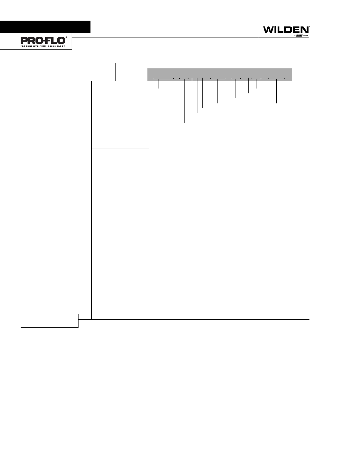
Section 2
WILDEN PUMP DESIGNATION SYSTEM
P1500/PV1500 METAL
76 mm (3") Pump
Maximum Flow Rate:
999 lpm (264 gpm)
MATERIAL CODES
MODEL
P1500 = PRO-FLO
PV15 0 0 = PRO-FLO V™
WETTED PARTS
AA = ALUMINUM / ALUMINUM
AS = ALUMINUM /
HH = ALLOY C / ALLOY C
SS = STA INL ESS STEEL /
AIR CHAMBERS & OUTER PISTON
A = ALUMINUM
C = P TFE COATED
S = STAINLE SS STEEL
CENTER BLOCK
A = ALUMINUM
C = P TFE COATED
AIR VALVE
A = ALUMINUM ( PV1500 only)
C = P TFE COATED
P = POLYPROPYLENE
LEGEND
STAINLESS STEEL
STAINLESS STEEL
(PV1500 only )
(P1500 only)
P1500/XXXXX/XXX/XX/XXX/ XXXX
MODEL
DIAPHRAGMS
AIR VALVE
CENTER BLOCK
AIR CHAMBERS
WETTED PARTS & OUTER PISTON
®
DIAPHRAGMS
BNS = BUNA-N (Red Dot)
BNU = BUNA-N, ULTRA-FLEX™
EPS = EPDM (Blue Dot)
EPU = EPDM, ULTRA-FLEX™
FSS = SANIFLEX™
[Hytrel® (Cream)]
NES = NEOPRENE (Green Dot)
NEU = NEOPRENE, ULTRA-FLEX™
PUS = POLYURE THA NE ( Clear)
TEU = PTFE W/EPDM
BACK-UP (White)
TNU = PTFE W/NEOPRENE
BACK-UP (White)
TSU = PTFE W/SANIFLEX™ BACK-
UP (White)
VTS = VITON® (White Dot)
VTU = VITON®, ULTRA-FLEX™
WFS = WIL-FLEX™ [Santoprene®
(Orange Dot)]
XBS = CONDUCTIVE BUNA-N (Two
Red Dots)
ULTRA-FLEX™ DIAPHRAGMS
UB = BUNA-N (Red Dot)
UE = EPDM (Blue Dot)
UN = NEOPRENE (Green Dot)
UV = VITON® (Silver or Whi te
Dot)
VALVE BALLS
VALVE BALL
BN = BUNA-N (Red Dot )
FG = SA NIFLEX™
EP = EPDM (Blue Dot)
NE = NEOPRENE (Green Dot)
PU = POLYURE THA NE (Clear)
TF = PTFE (Whi te)
VT = VITON® (Silver or Whi te Dot)
WF = WIL-F LE X ™ [S anto pren e
VALVE SE AT
BN = DIAPHRAGMS
FG = SA NIFLEX™
H = ALLOY C
EP = EPDM (Blue Dot)
NE = EPDM (Blue Dot)
PU = POLYURE THA NE (Clear)
S = S TAINLESS STEEL
VT = VITON® (White Dot)
WF = WIL-F LE X ™ [S anto pren e
VALVE SEAT O-RING
FS = FLUORO-SEAL™
TF = PTFE
TV = PT FE ENCAP. VITON
O-RINGS
VALVE SE AT
[Hytrel® (Cream)]
(Orange Dot) ]
[Hytrel® (Cream)]
(Orange Dot) ]
SPECIALTY
CODE
(if applicable)
®
SPECIALTY CODES
0003 Spark free
0010 SS outer piston, spark free
0100 Wil-Gard™ 110V
0102 Wil-Gard™ sensor wires ONLY
0103 Wil-Gard™ 220V
0104 Wil-Gard II™ 110V, spark free
0105 Wil-Gard II™ 220V, spark free
0480 Pump Cycle Monitor (sensor & wires)
0483 Pump Cycle Monitor (module, sensor & wires)
NOTE: MOST EL ASTOMERIC MATERI ALS USE COLOR ED DOTS FOR IDEN TIFICATION.
NOTE: Not all models are available with all material options.
®
Viton
is a registered trademark of DuPont Dow Elastomers.
WILDEN PUMP & ENGINEERING, LLC 2 WI L-11170 -E -0 8
0485 Pump Cycle Monitor (module, sensor & wires),
DIN flange
0513 SS outer pistons
0677 Inlet & discharge, NPT
0678 Inlet & discharge, BSPT
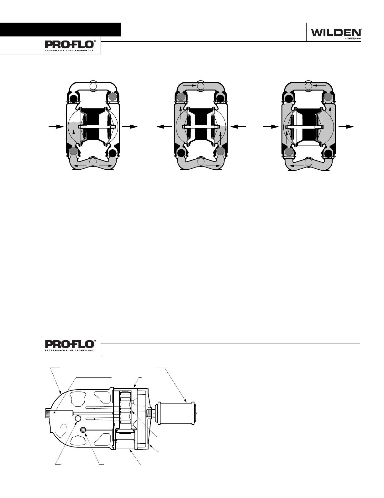
Section 3
HOW IT WORKS—PUMP
The Wilden diaphragm pump is an air-operated, positive displacement, self-priming pump. These drawings show fl ow pattern
through the pump upon its initial stroke. It is assumed the pump has no fl uid in it prior to its initial stroke.
#,/3%$
/54,%4
/0%.
"!
).,%4
FIGURE 1 The air valve dir ects pre ssurized
air to the back side of diaphragm A. The
compressed air is applied directly to the
liquid column separated by elastomeric
diaphragms. The diaphragm acts as
a separation membrane bet ween the
compressed air and liquid, balancing the
load and removing mechanical stress
from the diaphragm. The compressed
air moves the diaphragm away from
the center of the pump. The opposite
diaphragm is pulled in by the shaft
connected to the pressurized diaphragm.
Diaphragm B is on its suction stroke; air
behind the diaphragm has been forced
out to atmosphere through the exhaust
port of the pump. The movement of
diaphragm B toward the center of the
pump creates a vacuum within chamber B.
Atmospheric pressure forces fl uid into
the inlet manifold forcing the inlet valve
ball off its seat. Liquid is free to move
past the inlet valve ball and fi ll the liquid
chamber (see shaded area).
#,/3%$/0%.
#,/3%$ /0%.
FIGURE 2 When the pressurized diaphragm,
diaphr agm A, re ache s the limit of i ts dis charge
stroke, the air valve redirects pressurized
air to the back side of diaphragm B. The
pressurized air forces diaphragm B away
from the center while pulling diaphragm A
to the center. Diaphragm B is now on its
discharge stroke. Diaphragm B forces the
inlet valve ball onto its seat due to the
hydraulic forces developed in the liquid
chamber and manifold of the pump. These
same hydraulic forces lift the discharge
valve ball off its seat, while the opposite
discharge valve ball is forced onto its seat,
forcing fl uid to fl ow through the pump
discharge. The movement of diaphragm A
toward the center of the pump creates a
vacuum within liquid chamber A. Atmospheric pressure forces fl uid into the inlet
manifold of the pump. The inlet valve ball
is forced off its seat allowing the fl uid being
pumped to fi ll the liquid chamber.
/0%.
"!
/54,%4
).,%4
#,/3%$
#,/3%$ /0%.
"!
/0%.
FIGURE 3 At completion of the stroke,
the air valve again redirects air to the
back side of diaphragm A, which starts
diaphragm B on its exhaust stroke. As
the pump reaches its original starting
point, each diaphragm has gone through
one exhaust and one discharge stroke.
This constitutes one complete pumping
cycle. The pump may take several cycles
to completely prime depending on the
conditions of the application.
/54,%4
).,%4
#,/3%$
HOW IT WORKS—AIR DISTRIBUTION SYSTEM
-5&&,%2#%.4%23%#4)/.
!)2).,%4 !)26!,6%
!)26!,6%30//,
-5&&,%20,!4%
-!).3(!&4
WI L-11170 -E -0 8 3 WILDEN PUMP & ENGINEERING, LLC
0),/430//,
%.$#!0
The Pro-Flo
moving parts: the air valve spool and the pilot spool. The heart of
the system is the air valve spool and air valve. This valve design
incorporates an unbalanced spool. The smaller end of the spool
is pressurized continuously, while the large end is alternately
pressurized then exhausted to move the spool. The spool directs
pressurized air to one air chamber while exhausting the other.
The air causes the main shaft/diaphragm assembly to shift to
one side — discharging liquid on that side and pulling liquid in
on the other side. When the shaf t reaches the end of its stroke,
the inner piston actuates the pilot spool, which pressurizes and
exhausts the large end of the air valve spool. The repositioning
of the air valve spool routes the air to the other air chamber.
®
patented air distribution system incorporates two
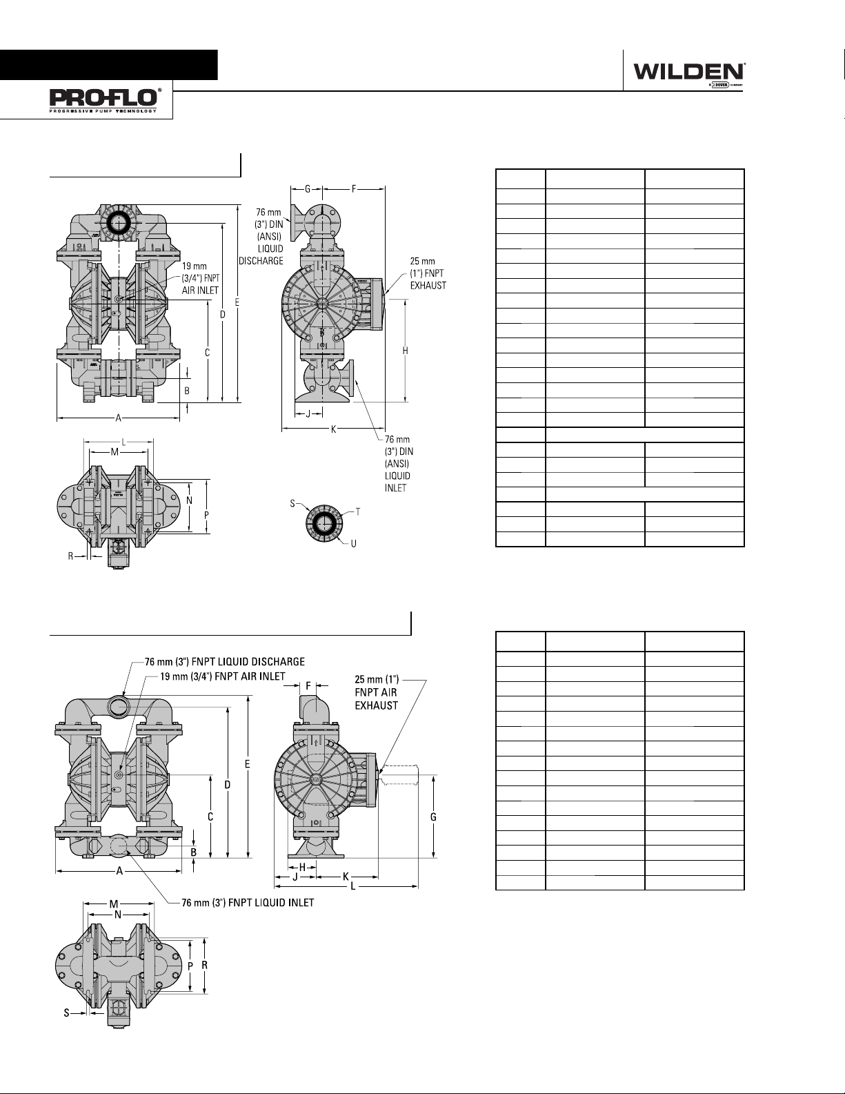
Section 4
DIMENSIONAL DRAWINGS
P1500 Aluminum
DIMENSIONS
ITEM METRIC (mm) STANDARD (inch)
A 615 24.2
B 127 5.0
C 533 21.0
D 934 36.8
E 1031 40.6
F 165 6.5
G 536 21.1
H 48 1.9
J 211 8.3
K 422 16.6
L 597 23.5
M 363 14.3
N 307 12.1
P 259 10.2
R 282 11.1
S 18 0.7
DIN FLANGE
T 200 DIA. 7.9 DIA.
U 160 DIA. 6.3 DIA.
V 18 DIA. 0.7 DIA.
ANSI FLANGE
T 191 DIA. 7.5 DIA.
U 152 DIA. 6.0 DIA.
V 19 DIA. 0.8 DIA.
PV1500 Aluminum Drop In Type
DIMENSIONS
ITEM METRIC (mm) STANDARD (inch)
A 635 25.0
B 61 2.4
C 419 16.5
D 759 29.9
E 818 32.2
F 84 3.3
G 419 16.5
H 142 5.6
J 211 8.3
K 315 12.4
L 724 28.5
M 358 14.1
N 307 12.1
P 257 10.1
R 282 11.1
S 15 0.6
WILDEN PUMP & ENGINEERING, LLC 4 WI L-11170 -E -0 8
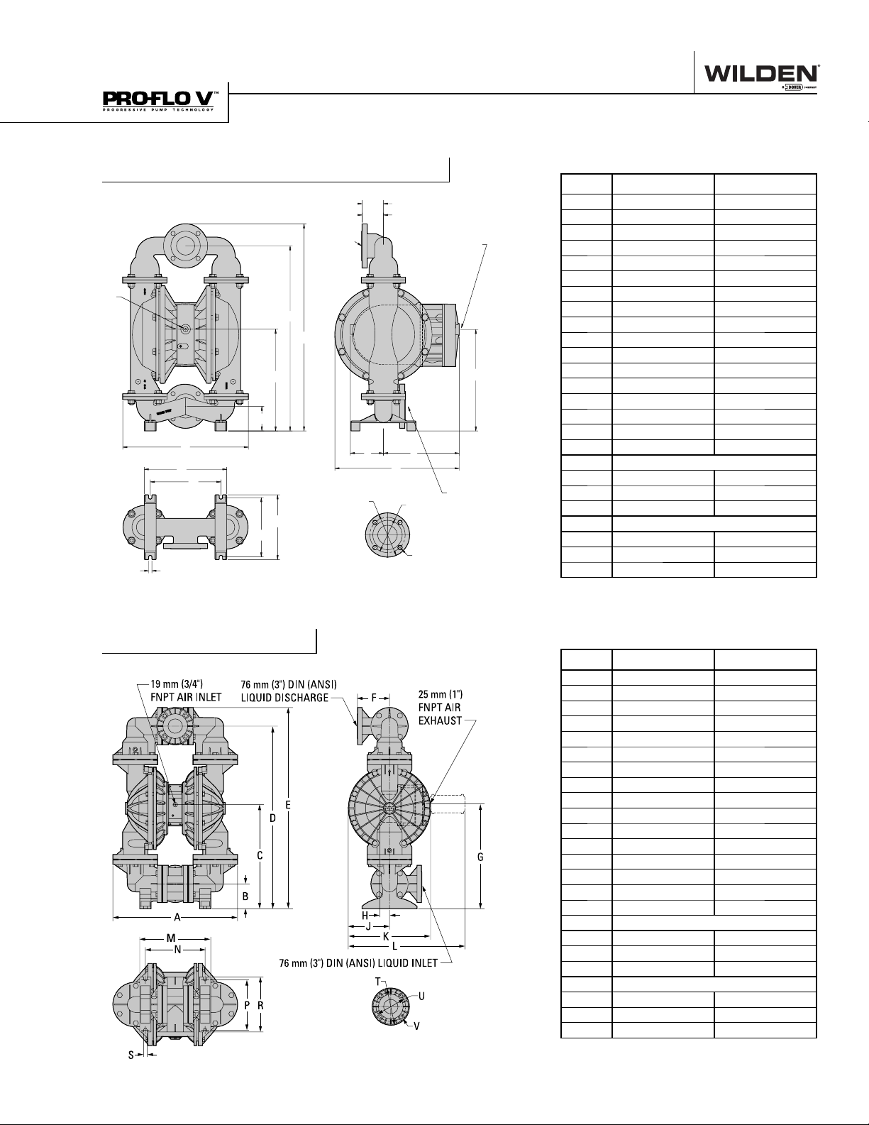
DIMENSIONAL DRAWINGS
P1500 Stainless Steel/Alloy C
F (DIN)
G (ANSI)
76 mm
(3") DIN
(ANSI)
19 mm
(3/4") FNPT
AIR INLET
C
B
A
M
N
R
P
S
LIQUID
DISCHARGE
D
E
J
T
DIMENSIONS
ITEM METRIC (mm) STANDARD (inch)
A 541 21.3
25 mm
(1") FNPT
AIR
EXHAUST
H
L
76 mm
(3") DIN
U
(ANSI)
LIQUID
INLET
V
B 107 4.2
C 434 17.1
D 798 31.4
E 894 35.2
F 89 3.5
G 91 3.6
H 437 17.2
J 48 1.9
K 211 8.3
L 178 7.0
M 597 23.5
N 356 14
P 305 12.0
R 257 10.1
S 279 11
T 15 0.6
DIN FLANGE
U 200 DIA. 7.9 DIA.
V 160 DIA. 6.3 DIA.
W 18 DIA. 0.7 DIA.
ANSI FLANGE
U 191 DIA. 7.5 DIA.
V 152 DIA. 6.0 DIA.
W 19 DIA. 0.8 DIA.
PV1500 Aluminum
19 mm (3/4")
FNPT AIR INLET
A
M
N
76 mm (3") DIN (ANSI)
LIQUID DISCHARGE
E
D
C
B
76 mm (3") DIN (ANSI) LIQUID INLET
P
R
DIMENSIONS
ITEM METRIC (mm) STANDARD (inch)
A 615 24.2
F
H
J
T
25 mm (1")
FNPT AIR
EXHAUST
G
K
L
U
V
B 127 5.0
C 533 21.0
D 934 36.8
E 1031 40.6
F 165 6.5
G 536 21.1
H 48 1.9
J 211 8.3
K 422 16.6
L 597 23.5
M 363 14.3
N 307 12.1
P 259 10.2
R 282 11.1
S 18 0.7
DIN FLANGE
T 200 DIA. 7.9 DIA.
U 160 DIA. 6.3 DIA.
V 18 DIA. 0.7 DIA.
ANSI FLANGE
T 191 DIA. 7.5 DIA.
U 152 DIA. 6.0 DIA.
V 19 DIA. 0.8 DIA.
S
WI L-11170 -E -0 8 5 WILDEN PUMP & ENGINEERING, LLC
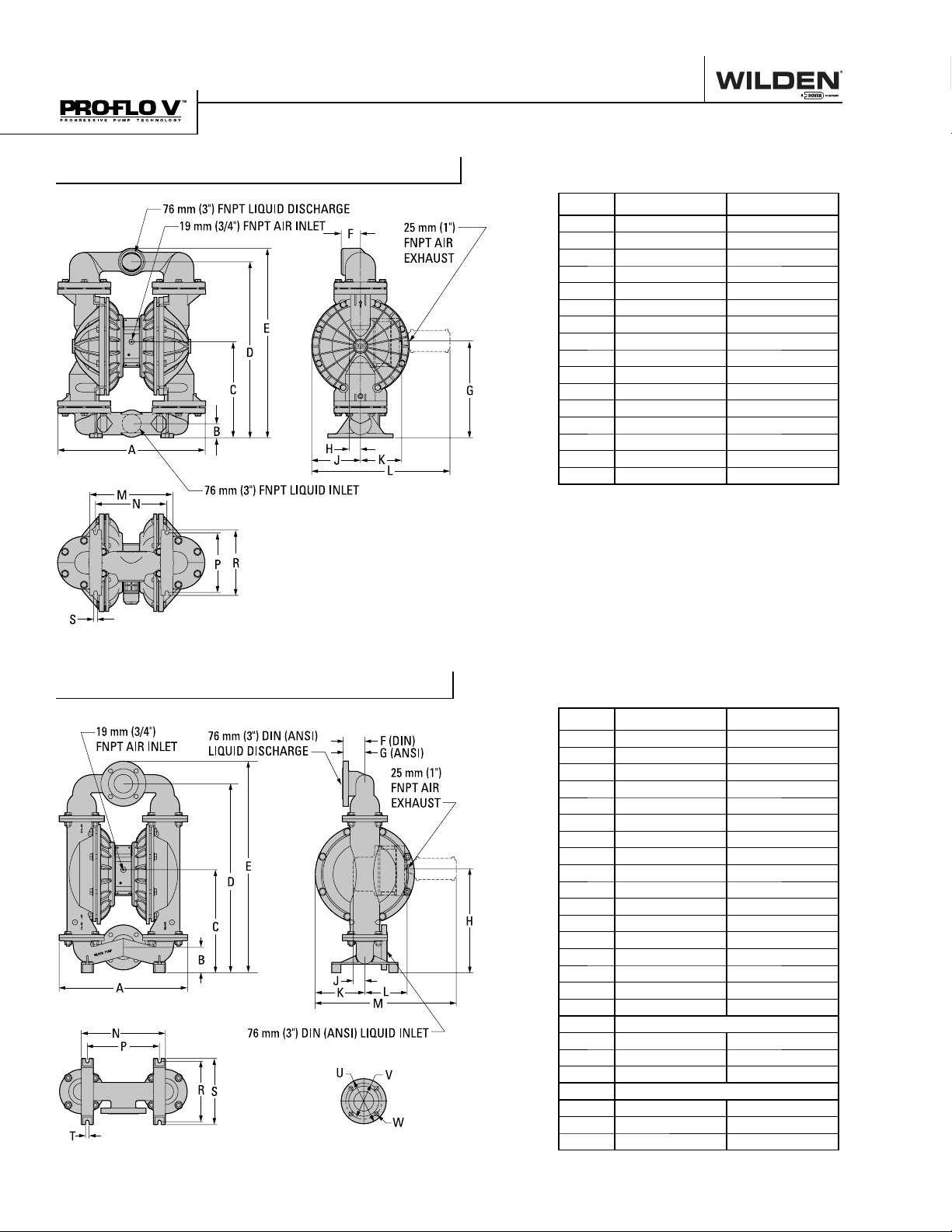
DIMENSIONAL DRAWINGS
PV1500 Aluminum Drop In Type
DIMENSIONS
ITEM METRIC (mm) STANDARD (inch)
A 635 25.0
B 61 2.4
C 414 16.3
D 759 29.9
E 818 32.2
F 84 3.3
G 417 16.4
H 48 1.9
J 211 8.3
K 178 7.0
L 597 23.5
M 358 14.1
N 307 12.1
P 257 10.1
R 282 11.1
S 15 0.6
PV1500 Stainless Steel/Alloy C
DIMENSIONS
ITEM METRIC (mm) STANDARD (inch)
A 541 21.3
B 107 4.2
C 434 17.1
D 798 31.4
E 894 35.2
F 89 3.5
G 91 3.6
H 437 17.2
J 48 1.9
K 211 8.3
L 178 7.0
M 597 23.5
N 356 14
P 305 12.0
R 257 10.1
S 279 11
T 15 0.6
DIN FLANGE
U 200 DIA. 7.9 DIA.
V 160 DIA. 6.3 DIA.
W 18 DIA. 0.7 DIA.
ANSI FLANGE
U 191 DIA. 7.5 DIA.
V 152 DIA. 6.0 DIA.
W 19 DIA. 0.8 DIA.
WILDEN PUMP & ENGINEERING, LLC 6 WI L-11170 -E -0 8
Section 5A
PERFORMANCE
P1500 ALUMINUM
RUBBER-FITTED
Height ...............................1031 mm (40.6")
Width ..................................615 mm (24.2")
Depth ..................................538 mm (21.2" )
Est. Ship Weight ...Aluminum 83 kg (182 lbs)
Air Inlet ....................................19 mm (3/4")
Inlet ........................................... 76 mm (3")
Outlet ........................................ 76 mm (3")
Suction Lif t .........................6.7 m Dry (22')
9.1 m Wet (30')
Displacement/Stroke ......5.41 l (1.43 gal.)
Max. Flow Rate ........... 973 lpm (257 gpm)
Max. Size Solids ................. 12.7 mm (1/2" )
1
Displacement per stroke was calculated
at 4.8 bar (70 psig) air inlet pressure
against a 2.1 bar (30 psig) head pressure.
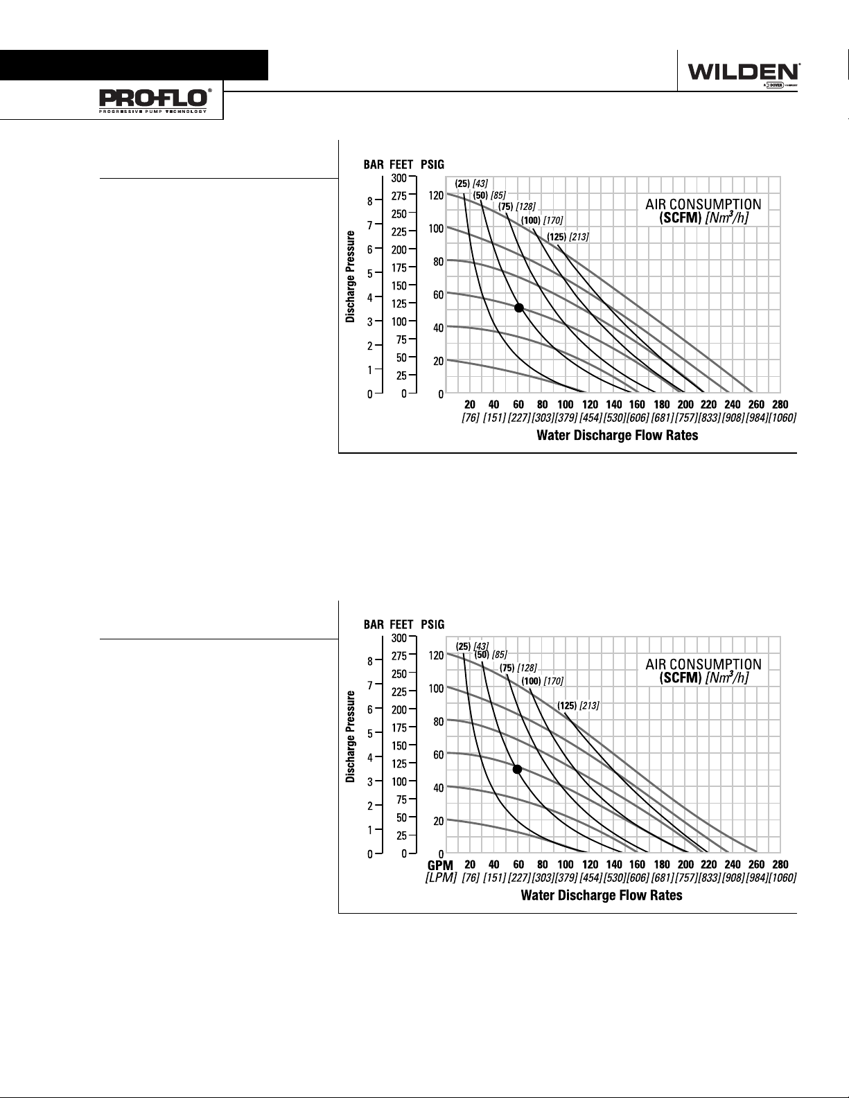
Example: To pump 227 lpm (60 gpm)
against a discharge pressure head of
3.6 bar (52 psig) requires 4.1 bar (60 psig)
and 82 Nm3/h (48 scfm) air consumption.
Caution: Do not exceed 8.6 bar (125 psig)
air supply pressure.
1
GPM
[LPM]
Flow rates indicated on chart were determined by pumping water.
For optimum life and performance, pumps should be specifi ed so that daily operation
parameters will fall in the center of the pump performance curve.
P1500 ALUMINUM
TPE-FITTED
Height ...............................1031 mm (40.6")
Width ..................................615 mm (24.2")
Depth ..................................538 mm (21.2" )
Est. Ship Weight ...Aluminum 83 kg (182 lbs)
Air Inlet ...................................19 mm (3/4")
Inlet ............................................ 76 mm ( 3")
Outle t ......................................... 76 mm (3" )
Suction Lif t .........................5.5 m Dry (18')
8.5 m Wet (28')
Displacement/Stroke ......5.41 l (1.43 gal.)
Max. Flow Rate ........... 984 lpm (260 gpm)
Max. Size Solids ................. 12.7 mm (1/2" )
1
Displacement per stroke was calculated
at 4.8 bar (70 psig) air inlet pressure
against a 2.1 bar (30 psig) head pressure.
Example: To pump 227 lpm (60 gpm)
against a discharge pressure head of
3.4 bar ( 50 psig) requires 3.9 bar (58 psig)
and 85 Nm
Caution: Do not exceed 8.6 bar (125 psig)
air supply pressure.
3
/h (50 scfm) air consumption.
1
Flow rates indicated on chart were determined by pumping water.
For optimum life and performance, pumps should be specifi ed so that daily operation
parameters will fall in the center of the pump performance curve.
WI L-11170 -E -0 8 7 WILDEN PUMP & ENGINEERING, LLC
PERFORMANCE
P1500 ALUMINUM
PTFE-FITTED
Height ...............................1031 mm (40.6")
Width ..................................615 mm (24.2")
Depth ..................................538 mm (21.2" )
Est. Ship Weight ...Aluminum 83 kg (182 lbs)
Air Inlet ...................................19 mm (3/4")
Inlet ............................................ 76 mm ( 3")
Outle t ......................................... 76 mm (3" )
Suction Lif t .........................5.2 m Dry (17')
8.5 m Wet (28')
Displacement/Stroke ......5.41 l (1.43 gal.)
Max. Flow Rate ............753 lpm (199 gpm)
Max. Size Solids ................. 12.7 mm (1/2" )
1
Displacement per stroke was calculated
at 4.8 bar (70 psig) air inlet pressure
against a 2.1 bar (30 psig) head pressure.
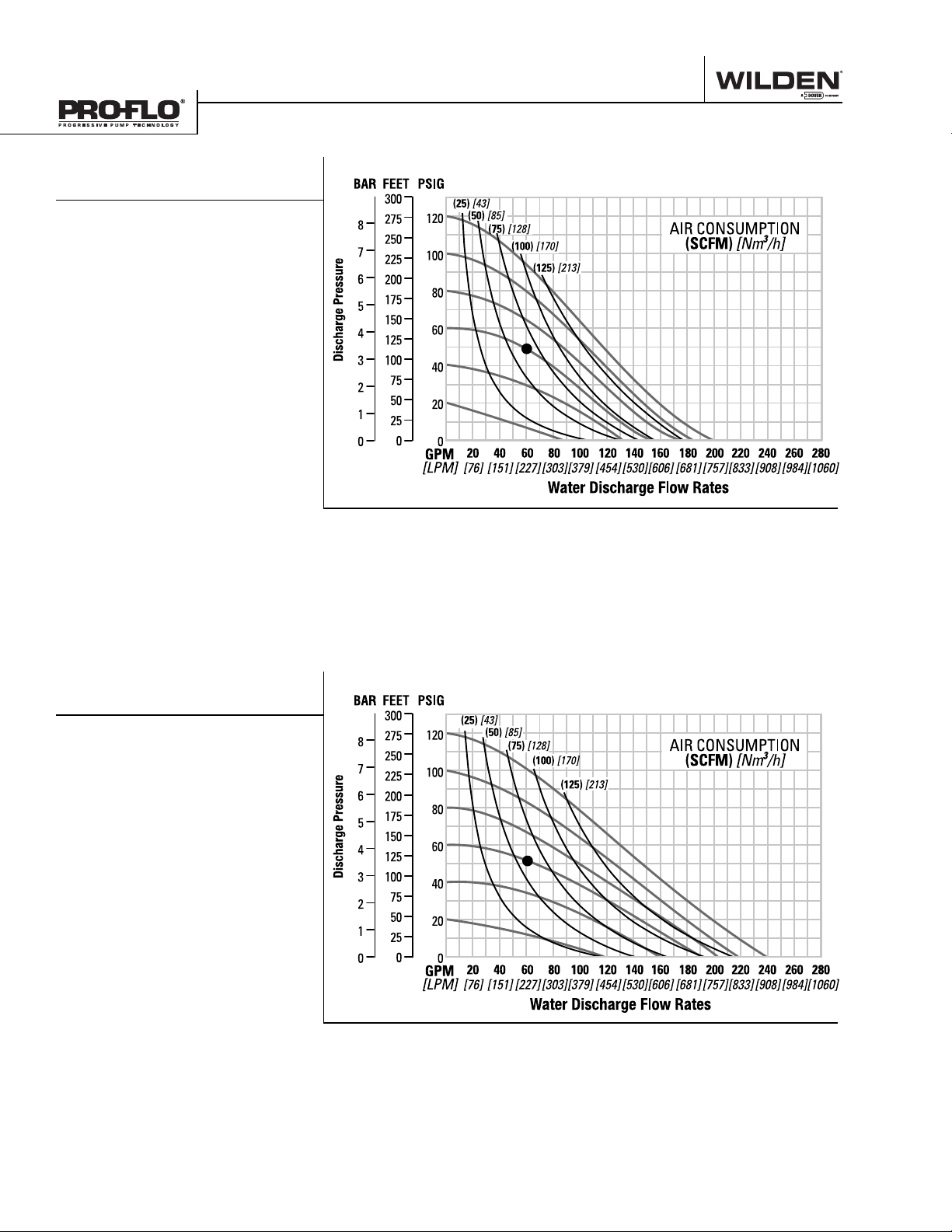
Example: To pump 227 lpm (60 gpm)
against a discharge pressure head of
3.3 bar (48 psig) requires 4.1 bar (60 psig)
and 109 Nm3/h (64 scfm) air consumption.
Caution: Do not exceed 8.6 bar (125 psig)
air supply pressure.
1
Flow rates indicated on chart were determined by pumping water.
For optimum life and performance, pumps should be specifi ed so that daily operation
parameters will fall in the center of the pump performance curve.
P1500 ALUMINUM
ULTRA-FLEX™-FITTED
Height ...............................1031 mm (40.6")
Width ..................................615 mm (24.2")
Depth ..................................538 mm (21.2" )
Est. Ship Weight ...Aluminum 83 kg (182 lbs)
Air Inlet ....................................19 mm (3/4")
Inlet ............................................ 76 mm ( 3")
Outle t ......................................... 76 mm (3" )
Suction Lif t .........................6.1 m Dry (20')
8.5 m Wet (28')
Displacement/Stroke ......5.41 l (1.43 gal.)
Max. Flow Rate ........... 905 lpm (239 gpm)
Max. Size Solids ................. 12.7 mm (1/2" )
1
Displacement per stroke was calculated
at 4.8 bar (70 psig) air inlet pressure
against a 2.1 bar (30 psig) head pressure.
Example: To pump 227 lpm (60 gpm)
against a discharge pressure head of
3.5 bar ( 51 psig) requires 4.1 bar (60 psig)
and 102 Nm
Caution: Do not exceed 8.6 bar (125 psig)
air supply pressure.
3
/h (60 scfm) air consumption.
1
Flow rates indicated on chart were determined by pumping water.
For optimum life and performance, pumps should be specifi ed so that daily operation
parameters will fall in the center of the pump performance curve.
WILDEN PUMP & ENGINEERING, LLC 8 WI L-11170 -E -0 8
PERFORMANCE
P1500 STAINLESS STEEL
RUBBER-FITTED
Height ................................ 894 mm (35.2" )
Width ..................................541 mm (21.3")
Depth .................................. 536 mm (21.1")
Est. Ship Weight ..........................................
316 Stainless Steel 125 kg (275 lbs)
Alloy C 130 kg (287 lbs)
Air Inlet ...................................19 mm (3/4")
Inlet ........................................... 76 mm (3")
Outlet ........................................ 76 mm (3")
Suction Lif t .........................6.7 m Dry (22')
9.5 m Wet (31')
Displacement/Stroke ......5.60 l (1.48 gal.)
Max. Flow Rate .......... 920 lpm (243 gpm)
Max. Size Solids .................. 9.5 mm (3/ 8" )
1
Displacement per stroke was calculated
at 4.8 bar (70 psig) air inlet pressure
against a 2.1 bar (30 psig) head pressure.
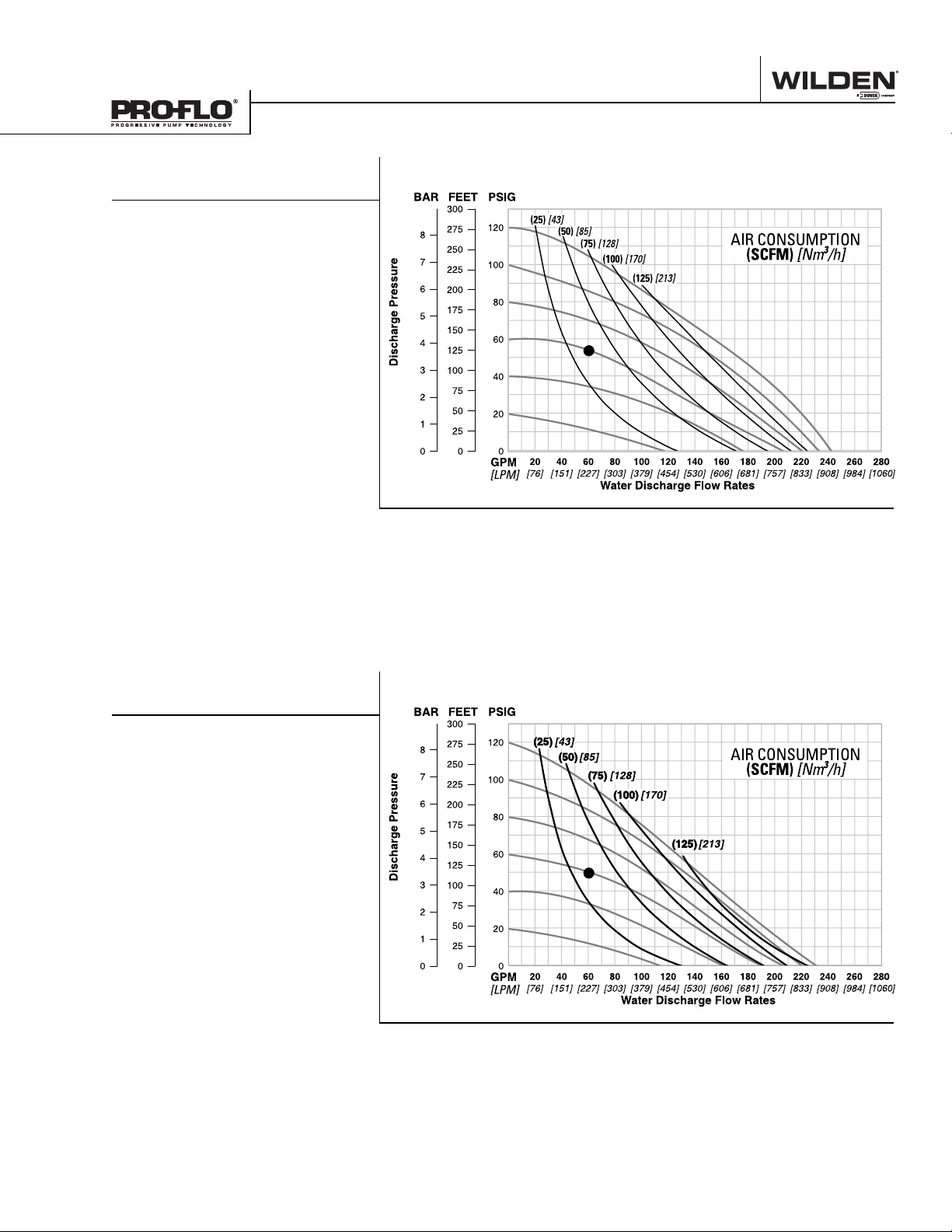
Example: To pump 227 lpm (60 gpm)
against a discharge pressure head of
3.7 bar (54 psig) requires 4.1 bar (60 psig)
and 61 Nm3/h (36 scfm) air consumption.
Caution: Do not exceed 8.6 bar (125 psig)
air supply pressure.
1
Flow rates indicated on chart were determined by pumping water.
For optimum life and performance, pumps should be specifi ed so that daily operation
parameters will fall in the center of the pump performance curve.
P1500 STAINLESS STEEL
TPE-FITTED
Height ................................ 894 mm (35.2" )
Width ..................................541 mm (21.3")
Depth .................................. 536 mm (21.1")
Est. Ship Weight ..........................................
316 Stainless Steel 125 kg (275 lbs)
Alloy C 130 kg (287 lbs)
Air Inlet ...................................19 mm (3/4")
Inlet ............................................ 76 mm ( 3")
Outle t ......................................... 76 mm (3" )
Suction Lif t .......................7.01 m Dry (23')
9.1 m Wet (30')
Displacement/Stroke ......5.6 4 l (1.49 gal.)
Max. Flow Rate ............878 lpm (232 gpm)
Max. Size Solids .................. 9.5 mm (3/ 8" )
1
Displacement per stroke was calculated
at 4.8 bar (70 psig) air inlet pressure
against a 2.1 bar (30 psig) head pressure.
Example: To pump 227 lpm (60 gpm)
against a discharge pressure head of
3.4 bar ( 50 psig) requires 4.1 bar (60 psig)
and 58 Nm3/h (34 scfm) air consumption.
Caution: Do not exceed 8.6 bar (125 psig)
air supply pressure.
1
Flow rates indicated on chart were determined by pumping water.
For optimum life and performance, pumps should be specifi ed so that daily operation
parameters will fall in the center of the pump performance curve.
WI L-11170 -E -0 8 9 WILDEN PUMP & ENGINEERING, LLC
PERFORMANCE
P1500 STAINLESS STEEL
PTFE-FITTED
Height ................................ 894 mm (35.2" )
Width ..................................541 mm (21.3")
Depth .................................. 536 mm (21.1")
Est. Ship Weight ..........................................
316 Stainless Steel 125 kg (275 lbs)
Alloy C 130 kg (287 lbs)
Air Inlet ...................................19 mm (3/4")
Inlet ............................................ 76 mm ( 3")
Outle t ......................................... 76 mm (3" )
Suction Lif t .........................4.9 m Dry (16')
9.1 m Wet (30')
Displacement/Stroke ..... 3.59 l (0.95 gal.)
Max. Flow Rate ............708 lpm (187 gpm)
Max. Size Solids .................. 9.5 mm (3/ 8" )
1
Displacement per stroke was calculated
at 4.8 bar (70 psig) air inlet pressure
against a 2.1 bar (30 psig) head pressure.
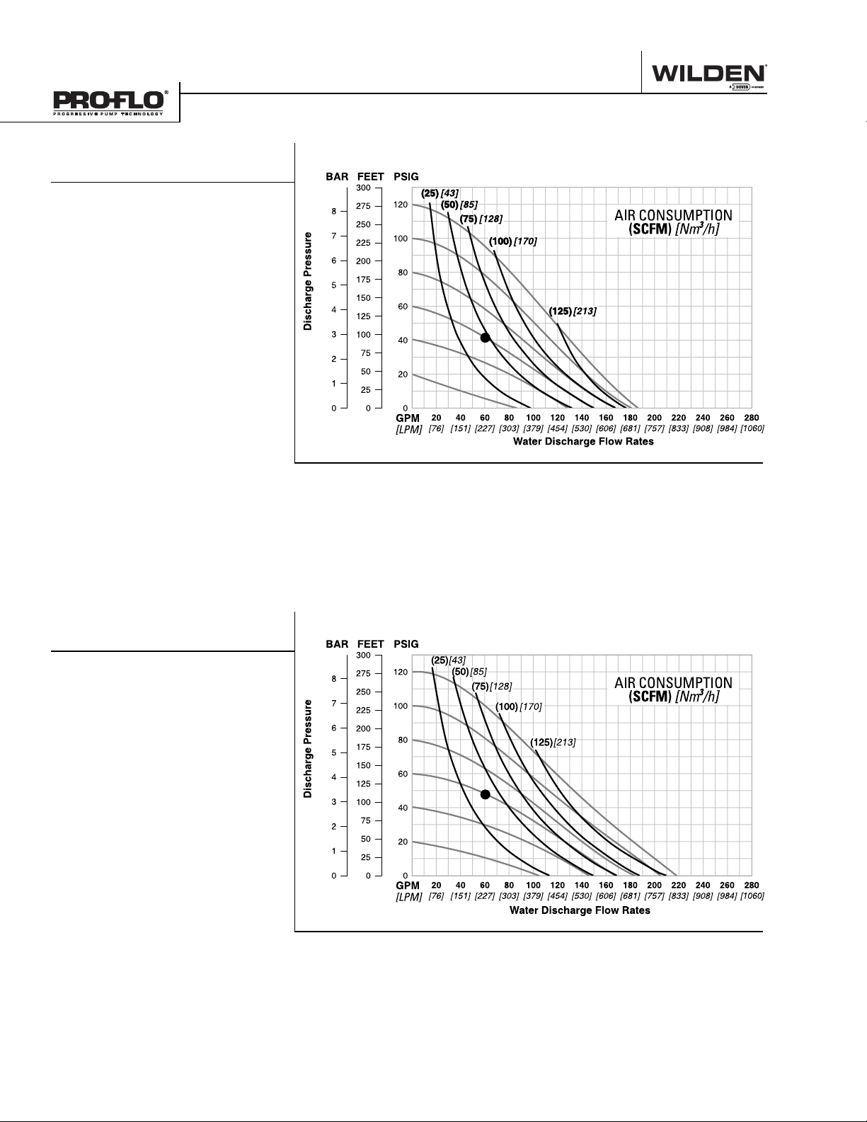
Example: To pump 227 lpm (60 gpm)
against a discharge pressure head of
2.9 bar (42 psig) requires 4.1 bar (60 psig)
and 80 Nm3/h (47 scfm) air consumption.
Caution: Do not exceed 8.6 bar (125 psig)
air supply pressure.
1
Flow rates indicated on chart were determined by pumping water.
For optimum life and performance, pumps should be specifi ed so that daily operation
parameters will fall in the center of the pump performance curve.
P1500 STAINLESS STEEL
ULTRA-FLEX™-FITTED
Height ................................ 894 mm (35.2" )
Width ..................................541 mm (21.3")
Depth .................................. 536 mm (21.1")
Est. Ship Weight ..........................................
316 Stainless Steel 125 kg (275 lbs)
Alloy C 130 kg (287 lbs)
Air Inlet ...................................19 mm (3/4")
Inlet ............................................ 76 mm ( 3")
Outle t ......................................... 76 mm (3" )
Suction Lif t .........................7.9 m Dry (26')
9.5 m Wet (31')
Displacement/Stroke ......4.61 l (1.22 gal.)
Max. Flow Rate ............825 lpm (218 gpm)
Max. Size Solids .................. 9.5 mm (3/ 8" )
1
Displacement per stroke was calculated
at 4.8 bar (70 psig) air inlet pressure
against a 2.1 bar (30 psig) head pressure.
Example: To pump 227 lpm (60 gpm)
against a discharge pressure head of
3.3 bar (48 psig) requires 4.1 bar (60 psig)
and 68 Nm
Caution: Do not exceed 8.6 bar (125 psig)
air supply pressure.
3
/h (40 scfm) air consumption.
1
Flow rates indicated on chart were determined by pumping water.
For optimum life and performance, pumps should be specifi ed so that daily operation
parameters will fall in the center of the pump performance curve.
WILDEN PUMP & ENGINEERING, LLC 10 WIL-1117 0- E-08

PERFORMANCE
PV1500 ALUMINUM
RUBBER-FITTED
Height ...............................1031 mm (40.6")
Width ..................................615 mm (24.2")
Depth ..................................422 mm (16.6" )
Est. Ship Weight ...Aluminum 78 kg (171 lbs)
Air Inlet ................................... 19 mm (3 ⁄4" )
Inlet ........................................... 76 mm (3")
Outlet ........................................ 76 mm (3")
Suction Lif t ......................6.6 m Dr y (21.6')
9.5 m Wet (31.2')
Displacement/Stroke ......5.68 l (1.50 gal.)
Max. Flow Rate .......... 984 lpm (260 gpm)
Max. Size Solids ................. 12.7 mm (1/2" )
1
Displacement per stroke was calculated
at 4.8 bar (70 psig) air inlet pressure
against a 2.1 bar (30 psig) head pressure.
Example: To pump 454 lpm (120 gpm)
against a discharge pressure head of
1.7 bar (24 psig) requires 2.8 bar (40 psig)
and 102 Nm3/h (60 scfm) air consumption.
Caution: Do not exceed 8.6 bar (125 psig)
air supply pressure.
1
Flow rates indicated on chart were determined by pumping water.
For optimum life and performance, pumps should be specifi ed so that daily operation
parameters will fall in the center of the pump performance curve.
PV1500 ALUMINUM
TPE-FITTED
Height ...............................1031 mm (40.6")
Width ..................................615 mm (24.2")
Depth ..................................422 mm (16.6" )
Est. Ship Weight ...Aluminum 78 kg (171 lbs)
Air Inlet ................................... 19 mm (3 ⁄4" )
Inlet ............................................ 76 mm ( 3")
Outle t ......................................... 76 mm (3" )
Suction Lif t ......................7.6 m Dry (25.0')
9.5 m Wet (31.2')
Displacement/Stroke ......5.79 l (1.53 gal.)
Max. Flow Rate ........... 999 lpm (26 4 gpm)
Max. Size Solids ................. 12.7 mm (1/2" )
1
Displacement per stroke was calculated
at 4.8 bar (70 psig) air inlet pressure
against a 2.1 bar (30 psig) head pressure.
Example: To pump 473 lpm (125 gpm)
against a discharge pressure head of
1.4 bar (20 psig) requires 2.8 bar (40
psig) and 102 Nm
consumption.
Caution: Do not exceed 8.6 bar (125 psig)
air supply pressure.
3
/h (60 scfm) air
1
Flow rates indicated on chart were determined by pumping water.
For optimum life and performance, pumps should be specifi ed so that daily operation
parameters will fall in the center of the pump performance curve.
WI L-11170 -E -0 8 11 WILDEN PUMP & ENGINEERING, LLC

PERFORMANCE
PV1500 ALUMINUM
PTFE-FITTED
Height ...............................1031 mm (40.6")
Width ..................................615 mm (24.2")
Depth ..................................422 mm (16.6" )
Est. Ship Weight ...Aluminum 78 kg (171 lbs)
Air Inlet ................................... 19 mm (3 ⁄4" )
Inlet ............................................ 76 mm ( 3")
Outle t ......................................... 76 mm (3" )
Suction Lif t ......................5.0 m Dry (16.5')
9.5 m Wet (31.2')
Displacement/Stroke ..... 3.56 l (0.94 gal.)
Max. Flow Rate ........... 772 lpm (204 gpm)
Max. Size Solids ................. 12.7 mm (1/2" )
1
Displacement per stroke was calculated
at 4.8 bar (70 psig) air inlet pressure
against a 2.1 bar (30 psig) head pressure.
Example: To pump 151 lpm (40 gpm)
against a discharge pressure head of
3.7 bar (53 psig) requires 4.1 bar (60 psig)
and 68 Nm3/h (40 scfm) air consumption.
Caution: Do not exceed 8.6 bar (125 psig)
air supply pressure.
1
Flow rates indicated on chart were determined by pumping water.
For optimum life and performance, pumps should be specifi ed so that daily operation
parameters will fall in the center of the pump performance curve.
PV1500 ALUMINUM
ULTRA-FLEX™-FITTED
Height ...............................1031 mm (40.6")
Width ..................................615 mm (24.2")
Depth ..................................422 mm (16.6" )
Est. Ship Weight ...Aluminum 78 kg (171 lbs)
Air Inlet ................................... 19 mm (3 ⁄4" )
Inlet ............................................ 76 mm ( 3")
Outle t ......................................... 76 mm (3" )
Suction Lif t ......................6.1 m Dry (19.9')
9.5 m Wet (31.2')
Displacement/Stroke ......4.88 l (1.29 gal.)
Max. Flow Rate ........... 905 lpm (239 gpm)
Max. Size Solids ................. 12.7 mm (1/2" )
1
Displacement per stroke was calculated
at 4.8 bar (70 psig) air inlet pressure
against a 2.1 bar (30 psig) head pressure.
Example: To pump 189 lpm (50 gpm)
against a discharge pressure head of
3.7 bar (53 psig) requires 4.1 bar (60 psig)
and 68 Nm3/h (40 scfm) air consumption.
Caution: Do not exceed 8.6 bar (125 psig)
air supply pressure.
1
Flow rates indicated on chart were determined by pumping water.
For optimum life and performance, pumps should be specifi ed so that daily operation
parameters will fall in the center of the pump performance curve.
WILDEN PUMP & ENGINEERING, LLC 12 WIL-1117 0- E-08

PERFORMANCE
PV1500 STAINLESS STEEL
RUBBER-FITTED
Height ................................ 894 mm (35.2" )
Width ..................................541 mm (21.3")
Depth .................................. 419 mm (16.5")
Est. Ship Weight ..........................................
316 Stainless Steel 120 kg (264 lbs)
Alloy C 125 kg (276 lbs)
Air Inlet ...................................19 mm (3/4")
Inlet ........................................... 76 mm (3")
Outle t ......................................... 76 mm (3" )
Suction Lif t ......................6.6 m Dr y (21.6')
9.5 m Wet (31.2')
Displacement/Stroke ......5.53 l (1.46 gal.)
Max. Flow Rate .......... 908 lpm (240 gpm)
Max. Size Solids .................. 9.5 mm (3/ 8" )
1
Displacement per stroke was calculated
at 4.8 bar (70 psig) air inlet pressure
against a 2.1 bar (30 psig) head pressure.
Example: To pump 454 lpm (120 gpm)
against a discharge pressure head of
3.6 bar (52 psig) requires 5.5 bar (80 psig)
and 170 Nm3/h (100 scfm) air consumption.
Caution: Do not exceed 8.6 bar (125 psig)
air supply pressure.
1
Flow rates indicated on chart were determined by pumping water.
For optimum life and performance, pumps should be specifi ed so that daily operation
parameters will fall in the center of the pump performance curve.
PV1500 STAINLESS STEEL
TPE-FITTED
Height ................................ 894 mm (35.2" )
Width ..................................541 mm (21.3")
Depth .................................. 419 mm (16.5")
Est. Ship Weight ..........................................
316 Stainless Steel 120 kg (264 lbs)
Alloy C 125 kg (276 lbs)
Air Inlet ...................................19 mm (3/4")
Inlet ............................................ 76 mm ( 3")
Outle t ......................................... 76 mm (3" )
Suction Lif t ......................7.6 m Dry (25.0')
9.5 m Wet (31.2')
Displacement/Stroke ...... 5.72 l (1.51 gal.)
Max. Flow Rate ........... 905 lpm (239 gpm)
Max. Size Solids .................. 9.5 mm (3/ 8" )
1
Displacement per stroke was calculated
at 4.8 bar (70 psig) air inlet pressure
against a 2.1 bar (30 psig) head pressure.
Example: To pump 454 lpm (120 gpm)
against a discharge pressure head of
2.6 bar (38 psig) requires 4.1 bar (60 psig)
and 136 Nm3/h (80 scfm) air consumption.
Caution: Do not exceed 8.6 bar (125 psig)
air supply pressure.
1
Flow rates indicated on chart were determined by pumping water.
For optimum life and performance, pumps should be specifi ed so that daily operation
parameters will fall in the center of the pump performance curve.
WI L-11170 -E -0 8 13 WILDEN PUMP & ENGINEERING, LLC

PERFORMANCE
PV1500 STAINLESS STEEL
PTFE-FITTED
Height ................................ 894 mm (35.2" )
Width ..................................541 mm (21.3")
Depth .................................. 419 mm (16.5")
Est. Ship Weight ..........................................
316 Stainless Steel 120 kg (264 lbs)
Alloy C 125 kg (276 lbs)
Air Inlet ...................................19 mm (3/4")
Inlet ............................................ 76 mm ( 3")
Outle t ......................................... 76 mm (3" )
Suction Lif t ......................5.0 m Dry (16.5')
9.5 m Wet (31.2')
Displacement/Stroke ..... 3.48 l (0.92 gal.)
Max. Flow Rate ............704 lpm (186 gpm)
Max. Size Solids .................. 9.5 mm (3/ 8" )
1
Displacement per stroke was calculated
at 4.8 bar (70 psig) air inlet pressure
against a 2.1 bar (30 psig) head pressure.
Example: To pump 151 lpm (40 gpm)
against a discharge pressure head of
3.5 bar ( 51 psig) requires 4.1 bar (60 psig)
and 68 Nm3/h (40 scfm) air consumption.
Caution: Do not exceed 8.6 bar (125 psig)
air supply pressure.
1
Flow rates indicated on chart were determined by pumping water.
For optimum life and performance, pumps should be specifi ed so that daily operation
parameters will fall in the center of the pump performance curve.
PV1500 STAINLESS STEEL
ULTRA-FLEX™-FITTED
Height ................................ 894 mm (35.2" )
Width ..................................541 mm (21.3")
Depth .................................. 419 mm (16.5")
Est. Ship Weight ..........................................
316 Stainless Steel 120 kg (264 lbs)
Alloy C 125 kg (276 lbs)
Air Inlet ...................................19 mm (3/4")
Inlet ............................................ 76 mm ( 3")
Outle t ......................................... 76 mm (3" )
Suction Lif t ......................6.1 m Dry (19.9')
9.5 m Wet (31.2')
Displacement/Stroke ......4.69 l (1.24 gal.)
Max. Flow Rate ........... 856 lpm (226 gpm)
Max. Size Solids .................. 9.5 mm (3/ 8" )
1
Displacement per stroke was calculated
at 4.8 bar (70 psig) air inlet pressure
against a 2.1 bar (30 psig) head pressure.
Example: To pump 303 lpm (80 gpm)
against a discharge pressure head of
4.3 bar (62 psig) requires 5.5 bar (80 psig)
and 136 Nm
Caution: Do not exceed 8.6 bar (125 psig)
air supply pressure.
3
/h (80 scfm) air consumption.
1
Flow rates indicated on chart were determined by pumping water.
For optimum life and performance, pumps should be specifi ed so that daily operation
parameters will fall in the center of the pump performance curve.
WILDEN PUMP & ENGINEERING, LLC 14 WIL-1117 0- E-08

Section 5B
SUCTION LIFT CURVES
P1500 ALUMINUM
SUCTION LIFT
CAPABILITY
-%4%2 &4(
$RY6ACUUM
03)'
;"!2=
4RADITIONAL2UBBER$IAPHRAGMS
5LTRA&LEXÍ
$IAPHRAGMS
40%$IAPHRAGMS
;= ;= ;= ;= ;= ;= ;= ;= ;= ;=
04&%$IAPHRAGMS
)NLET!IR0RESSURE
P1500 STAINLESS STEEL
& ALLOY C SUCTION
LIFT CAPABILITY
Suction lift curves are calibrated for pumps operating
at 305 m (1,000') above sea level. This chart is meant
to be a guide only. There are many variables which
can affect your pump’s operating characteristics. The
number of intake and discharge elbows, viscosity of
pumping fl uid, elevation (atmospheric pressure) and
pipe friction loss all affect the amount of suction lift
your pump will attain.
WI L-11170 -E -0 8 15 WILDEN PUMP & ENGINEERING, LLC

SUCTION LIFT CURVES
PV1500 ALUMINUM
SUCTION LIFT
CAPABILITY
PV1500 STAINLESS STEEL
& ALLOY C SUCTION
LIFT CAPABILITY
Suction lift curves are calibrated for pumps operating
at 305 m (1,000') above sea level. This chart is meant
to be a guide only. There are many variables which
can affect your pump’s operating characteristics. The
WILDEN PUMP & ENGINEERING, LLC 16 WIL-1117 0- E-08
number of intake and discharge elbows, viscosity of
pumping fl uid, elevation (atmospheric pressure) and
pipe friction loss all affect the amount of suction lift
your pump will attain.

NOTES
WI L-11170 -E -0 8 17 WILDEN PUMP & ENGINEERING, LLC

Section 6
SUGGESTED INSTALLATION
Wilden pumps are designed to meet the performance
requirements of even the most demanding pumping
applications. They have been designed and manufactured
to the highest standards and are available in a variety of
liquid path materials to meet your chemical resistance
needs. Refer to the performance section of this manual for
an in-depth analysis of the performance characteristics of
your pump. Wilden offers the widest variety of elastomer
options in the industry to satisfy temperature, chemical
compatibility, abrasion resistance and fl ex concerns.
The suction pipe size should be at least the equivalent or
larger than the diameter size of the suction inlet on your
Wilden pump. The suction hose must be non-collapsible,
reinforced type as these pumps are capable of pulling a high
vacuum. Discharge piping should also be the equivalent
or larger than the diameter of the pump discharge which
will help reduce friction losses. It is critical that all fi ttings
and connections are airtight or a reduction or loss of pump
suction capability will result.
INSTALLATION: Months of careful planning, study,
and selection efforts can result in unsatisfactory pump
performance if installation details are left to chance.
Premature failure and long term dissatisfaction can be
avoided if reasonable care is exercised throughout the
installation process.
LOCATION: Noise, safety, and other logistical factors usually
dictate where equipment will be situated on the production
fl oor. Multiple installations with confl icting requirements
can result in congestion of utility areas, leaving few choices
for additional pumps.
Within the framework of these and other existing conditions,
every pump should be located in such a way that six key
factors are balanced against each other to maximum
advantage.
ACCESS: First of all, the location should be accessible. If
it’s easy to reach the pump, maintenance personnel will
have an easier time carrying out routine inspections and
adjustments. Should major repairs become necessary, ease
of access can play a key role in speeding the repair process
and reducing total downtime.
AIR SUPPLY: Every pump location should have an air line
large enough to supply the volume of air necessary to
achieve the desired pumping rate. Use air pressure up to
a maximum of 8.6 bar (125 psig) depending on pumping
requirements.
For best results, the pumps should use a 5µ (micron) air
fi lter, needle valve and regulator. The use of an air fi lter
before the pump will ensure that the majority of any pipeline
contaminants will be eliminated.
SOLENOID OPERATION: When operation is controlled by a
solenoid valve in the air line, three-way valves should be
used. This valve allows trapped air between the valve and
the pump to bleed off which improves pump performance.
Pumping volume can be estimated by counting the number
of strokes per minute and then multiplying the fi gure by the
displacement per stroke.
MUFFLER: Sound levels are reduced below OSHA
specifi cations using the standard Wilden muffl er. Other
muffl ers can be used to further reduce sound levels, but
they usually reduce pump performance.
ELEVATION: Selecting a site that is well within the pump’s
dynamic lift capability will assure that loss-of-prime issues will
be eliminated. In addition, pump effi ciency can be adversely
affected if proper attention is not given to site location.
PIPING: Final determination of the pump site should not be
made until the piping challenges of each possible location
have been evaluated. The impact of current and future
installations should be considered ahead of time to make
sure that inadvertent restrictions are not created for any
remaining sites.
The best choice possible will be a site involving the shortest
and straightest hook-up of suction and discharge piping.
Unnecessary elbows, bends, and fi ttings should be avoided.
Pipe sizes should be selected to keep friction losses within
practical limits. All piping should be supported independently
of the pump. In addition, the piping should be aligned to
avoid placing stress on the pump fi ttings.
Flexible hose can be installed to aid in absorbing the forces
created by the natural reciprocating action of the pump. If the
pump is to be bolted down to a solid location, a mounting
pad placed between the pump and the foundation will assist
in minimizing pump vibration. Flexible connections between
the pump and rigid piping will also assist in minimizing
pump vibration. If quick-closing valves are installed at any
point in the discharge system, or if pulsation within a system
becomes a problem, a surge suppressor (SD Equalizer
should be installed to protect the pump, piping and gauges
from surges and water hammer.
If the pump is to be used in a self-priming application, make
sure that all connections are airtight and that the suction lift is
within the model’s ability. Note: Materials of construction and
elastomer material have an effect on suction lift parameters.
Please refer to the performance section for specifi cs.
When pumps are installed in applications involving fl ooded
suction or suction head pressures, a gate valve should be
installed in the suction line to permit closing of the line for
pump service.
Pumps in service with a positive suction head are most effi cient
when inlet pressure is limited to 0.5–0.7 bar (7–10 psig).
Premature diaphragm failure may occur if positive suction
is 0.7 bar (10 psig) and higher.
SUBMERSIBLE APPLICATIONS: Pro-Flo V™ pumps can be
used for submersible applications, when using the Pro-Flo
V™ submersible option. Turbo-Flo™ pumps can also be
used for submersible applications.
NOTE: Pro-Flo
ALL WILDEN PUMPS ARE CAPABLE OF PASSING SOLIDS.
A STRAINER SHOULD BE USED ON THE PUMP INTAKE TO
ENSURE THAT THE PUMP'S RATED SOLIDS CAPACITY IS
NOT EXCEEDED.
CAUTION: DO NOT EXCEED 8.6 BAR (125 PSIG) AIR
SUPPLY PRESSURE.
®
and Accu-Flo™ pumps are not submersible.
WILDEN PUMP & ENGINEERING, LLC 18 WIL-1117 0- E-08
®
)

SUGGESTED INSTALLATION
This illustration is a generic
representation of an air-operated
double-diaphragm pump.
MUFFLER
FLEXIBLE
CONNECTION
SUCTION
EQUALIZER
SURGE DAMPENER
(OPTIONAL)
GAUGE
(OPTIONAL)
SHUT OFF
VALVE
DISCHARGE
FLEXIBLE
CONNECTION
NEEDLE VALVE
COMBINATION
FILTER & REGULATOR
AIR SHUT OFF VALVE
NOTE: In the event of a power failure, the shut off valve
should be closed, if the restarting of the pump is not
desirable once power is regained.
AIR OPERATED PUMPS: To stop the pump from
operating in an emergency situation, simply close the
FOOTPAD
shut off valve (user supplied) installed in the air supply
line. A properly functioning valve will stop the air supply
to the pump, therefore stopping output. This shut off
valve should be located far enough away from the
pumping equipment such that it can be reached safely
in an emergency situation.
WI L-11170 -E -0 8 19 WILDEN PUMP & ENGINEERING, LLC

SUGGESTED OPERATION & MAINTENANCE
OPERATION: The P1500 and PV1500 are pre-lubricated,
and do not require in-line lubrication. Additional
lubrication will not damage the pump, however if the
pump is heavily lubricated by an external source, the
pump’s internal lubrication may be washed away. If the
pump is th e n move d to a no n - lubricated locatio n, it ma y
need to be dis asse mb l ed and re - lubrica t ed as des c ribed
in the ASSEMBLY/DISASSEMBLY INSTRUCTIONS.
Pump discharge rate can be controlled by limiting the
volume and /or pressure of the air supply to the pump.
An air regulat or is used to regulate air p ressure. A ne edle
valve is used to regulate volume. Pump discharge rate
c an al so be c on tr oll ed by thr ot tl in g t he pu mp di sc ha rg e
by partially closing a valve in the discharge line of the
pump. This action increases friction loss which reduces
fl ow rate. (See Section 5.) This is useful when the need
exists to control the pump from a remote location.
When the pump discharge pressure equals or exceeds
the air supply pressure, the pump will stop; no bypass
or pressure relief valve is needed, and pump damage
will not occur. The pump has reached a “deadhead”
situation and can be restarted by reducing the fl uid
TROUBLESHOOTING
discharge pressure or increasing the air inlet pressure.
The Wilden P1500 and PV1500 pumps run solely on
compressed air and do not generate heat, therefore
your process fl uid temperature will not be affected.
MAINTENANCE AND INSPECTIONS: Since each
application is unique, maintenance schedules may
be different for every pump. Frequency of use, line
pressure, viscosity and abrasiveness of process fl uid
all affect the parts life of a Wilden pump. Periodic
inspections have been found to of fer the best
means for preventing unscheduled pump downtime.
Personnel familiar with the pump’s construction and
service should be informed of any abnormalities that
are detected during operation.
RECORDS: When service is required, a record should
be made of all necessary repairs and replacements.
Over a period of time, such records can become a
valuable tool for predicting and preventing future
maintenance problems and unscheduled downtime. In
addition, accurate records make it possible to identify
pumps that are poorly suited to their applications.
Pump will not run or runs slowly.
1. Ensure that the air inlet pressure is at least 0.4 bar
(5 psig) above startup pressure and that the differential
pressure (the difference between air inlet and liquid
discharge pressures) is not less than 0.7 bar (10 psig).
2. Check air inlet fi lter for debris (see recommended
installation).
3. Check for extreme air leakage (blow by) which
would indicate worn seals/bores in the air valve,
pilot spool, main shaft.
4. Disassemble pump and check for obstructions
in the air passageways or objects which would
obstruct the movement of internal parts.
5. Check for sticking ball check valves. If material being
pumped is not compatible with pump elastomers,
swelling may occur. Replace ball check valves and
seals with proper elastomers. Also, as the check
valve balls wear out, they become smaller and can
become stuck in the seats. In this case, replace balls
and seats.
6. Check for broken inner piston which will cause the
air valve spool to be unable to shift.
7. Remove plug from pilot spool exhaust.
Pump runs but little or no product fl ows.
1. Check for pump cavitation; slow pump speed
down to allow thick material to fl ow into liquid
chambers.
WILDEN PUMP & ENGINEERING, LLC 20 WIL-1117 0- E-08
2. Verify that vacuum required to lift liquid is not
greater than the vapor pressure of the material
being pumped (cavitation).
3. Check for sticking ball check valves. If material being
pumped is not compatible with pump elastomers,
swelling may occur. Replace ball check valves and
seats with proper elastomers. Also, as the check
valve balls wear out, they become smaller and can
become stuck in the seats. In this case, replace balls
and seats.
Pump air valve freezes.
1. Check for excessive moisture in compressed
air. Either install a dryer or hot air generator for
compressed air. Alternatively, a coalescing fi lter
may be used to remove the water from the
compressed air in some applications.
Air bubbles in pump discharge.
1. Check for ruptured diaphragm.
2. Check tightness of outer pistons (refer to Section 7.)
3. Check tightness of fasteners and integrity of
o-rings and seals, especially at intake manifold.
4. Ensure pipe connections are airtight.
Product comes out air exhaust.
1. Check for diaphragm rupture.
2. Check tightness of outer pistons to shaft.

Section 7
PUMP DISASSEMBLY
Tools Required :
• 15/16" Wrench
• Adjustable Wrench
• Vise equipped w/
soft jaws (such as
plywood, plastic
or other suitable
material)
CAUTION: Before any maintenance or repair is attempted, the compressed air line
to the pump should be disconnected and all air pressure allowed to bleed from the
pump. Disconnect all intake, discharge, and air lines. Drain the pump by turning it
upside down and allowing any fl uid to fl ow into a suitable container. Be aware of
any hazardous effects of contact with your process fl uid.
NOTE: The model photographed for these instructions incorporates rubber
diaphragms, balls, and seats. Models with PTFE diaphragms, balls and seats are
the same except where noted.
Step 1
Please note alignment marks on
liquid chamber. Use to properly
align center section to liquid
chamber.
WI L-11170 -E -0 8 21 WILDEN PUMP & ENGINEERING, LLC
Step 2
Using a 15/16" wrench, loosen the
discharge manifold from the liquid
chambers.
Step 3
Remove the discharge manifold to
expose the valve balls and valve
seats. Inspect ball cage area of
manifold for excessive wear or
damage.

PUMP DISASSEMBLY
Step 4
After removing discharge valve balls
and valve seats, from the discharge
manifold and liquid chamber, inspect
for nicks, gouges, chemical attack or
abrasive wear. Note: Replace worn
parts with genuine Wilden parts for
reliable performance.
Step 5
Using a 15/16" wrench, loosen
the inlet manifold from the liquid
chambers.
Step 6
Remove the inlet valve balls and
valve seats from the inlet manifold
and inspect for nicks, gouges,
chemical attack or abrasive wear.
Step 7
Using a 15/16" wrench, loosen the
liquid chamber from the center
section.
WILDEN PUMP & ENGINEERING, LLC 22 WIL-1117 0- E-08
Step 8
The liquid chamber should be
removed to expose the diaphragm
and outer piston.
Step 9
Using one adjustable wrench,
loosen the diaphragm assembly
from the center section assembly.

PUMP DISASSEMBLY
Step 10A
Note: Due to varying torque values,
one of the following two situations
will occur. 1) The outer piston,
diaphragm and inner piston remain
attached to the shaft and the entire
assembly can be removed from the
center section.
Finding
Spares
A
Nightmare
?
PRODUCTS:
AODDP
(Air Operated Double
Diaphragm Pumps)
• Warren-Rupp
• ARO
• Other
®
®
Step 10B
2) The outer piston, diaphragm
and inner piston separate from the
shaft which remains connected to
the opposite side liquid chamber.
Inspect diaphragm assembly and
shaft for signs of wear or chemical
attack. Replace all worn parts with
genuine Wilden parts for reliable
performance.
Sleep
easier
with
Spectrom is not your typical after market part supplier. We do not simply sell pump
parts; we provide value added procurement solutions.
Our unique network enables us to purchase effectively, resulting in low cost solutions. We also know that low purchase price is not enough - quality, integrity and
inventory are also important. Spectrom is structured to provide Pre and Post sales
support, giving our customers value added application and pump knowledge.
PUMP PARTS
(Low Cost)
• Diaphragms
• Valve balls
• Valve seats
KNOWLEDGE
& SERVICE
• Competitive pricing
• Delivery
• Service
• Inventory
WI L-11170 -E -0 8 23 WILDEN PUMP & ENGINEERING, LLC
Contact us to have a procurement solution developed for you. We don’t just fit you
into a generic system, we develop specific solutions that achieve results.
Spectrom will ship your order from our facility within 3 working days!
WARNING: These parts may exhibit better life than OEM parts.
1-909-512-1261 www.spectromparts.com

AIR VALVE / CENTER SECTION DISASSEMBLY
Tools Required :
• 3/16" Hex Head Wrench
• 1/4" Hex Head Wrench
• Snap Ring Pliers
• O-Ring Pick
CAUTION: Before any maintenance or repair is attempted, the compressed air line
to the pump should be disconnected and all air pressure allowed to bleed from the
pump. Disconnect all intake, discharge, and air lines. Drain the pump by turning it
upside down and allowing any fl uid to fl ow into a suitable container. Be aware of
hazardous effects of contact with your process fl uid.
®
The Wilden P1500 and PV1500 metal pumps utilize a revolutionary Pro-Flo
distribution system. Proprietary composite seals reduce the co effi cient of friction
and allow the P1500 and PV1500 to run lube-free. Constructed of polypropylene or
aluminum, the Pro-Flo® air distribution system is designed to perform in on/off,
non-freezing, non-stalling, tough duty applications.
air
Step 1
Using a 3/16" Hex head wrench,
loosen air valve bolts.
WILDEN PUMP & ENGINEERING, LLC 24 WIL-1117 0- E-08
Step 2
Remove muffl er plate and air valve
bolts from air valve assembly
exposing muffl er gasket for
inspection. Replace if necessary.
Step 3
Lift away air valve assembly
and remove air valve gasket for
inspection. Replace if necessary.

AIR VALVE / CENTER SECTION DISASSEMBLY
Step 4
Remove air valve end cap to expose
air valve spool by simply lifting
up on end cap once air valve bolts
are removed. Note: Pro-Flo V™ air
valve incorporates an end cap at
both ends of the air valve.
Step 5
Remove the air valve spool from
the air valve body by threading one
air valve bolt into the end of the
air valve spool and gently sliding
the spool out of the air valve body.
Inspect seals for signs of wear and
replace entire assembly if necessary.
Use caution when handling air
valve spool to prevent damaging
seals. Note: Seals should not be
removed from assembly. Seals are
not sold separately.
Step 6
Remove pilot sleeve retaining snap
ring on both sides of center section
with snap ring pliers.
NOTCHED
END
Step 7
Remove pilot spool sleeve from
center section.
Step 8
Using an o-ring pick, gently remove the o-ring from the opposite side of the
“notched end“ on one side of the pilot spool. Gently remove the pilot spool
from pilot spool sleeve and inspect for nick, gouges and wear. Replace
pilot sleeve or outer sleeve o-rings if necessary. During re-assembly, never
insert the pilot spool into the sleeve with the “notched end“ fi rst, this end
incorporates the urethane o-ring and will be damaged as it slides over the
ports cut in the sleeve. Note: Seals should not be removed from pilot
spool. Seals are not sold separately.
WI L-11170 -E -0 8 25 WILDEN PUMP & ENGINEERING, LLC

AIR VALVE / CENTER SECTION DISASSEMBLY
Step 9
Check center section shaft seals for
signs of wear. If necessary, remove
the shaft seals with o-ring pick
and replace.
SUBMERSIBLE PRO-FLO V™
Step 1
Install a 6 mm (1/4”) NPT pipe plug
(00-7010-08) into the pilot spool
bleed port located at the front of the
center block.
Non-Submersible Submersible
Step 2
Next, install an optional submersible air valve gasket
(04-2621-52). The submersible air valve gasket can
be purchased as a spare part or included with the
purchase of a new Pro-Flo V™ pump.
WILDEN PUMP & ENGINEERING, LLC 26 WIL-1117 0- E-08

REASSEMBLY HINTS & TIPS
ASSEMBLY:
Upon performing applicable maintenance to the air
distrib ution system, th e pump can now be rea ssembled.
Please refer to the disassembly instructions for photos
and parts placement. To reassemble the pump, follow
the disassembly instructions in reverse order. The air
distribution system needs to be assembled fi rst, then
the diaphragms and fi nally the wetted path. Please fi nd
the applicable torque specifi cations on this page. The
following tips will assist in the assembly process.
• Lubricate air valve bore, center section shaft
and pilot spool bore with NLGI grade 2 white EP
bearing grease or equivalent.
• Clean the inside of the center section shaft bore to
ensure no damage is done to new shaft seals.
• A small amount NLGI grade 2 white EP bearing
grease can be applied to the muffl er and air valve
gaskets to locate gaskets during assembly.
• Make sure that the exhaust port on the muffl er plate
is centered between the two exhaust ports on the
center section.
• Stainless bolts should be lubed to reduce the
possibility of seizing during tightening.
• Use a mallet to tamp lightly on the large clamp
bands to seat the diaphragm before tightening.
PRO-FLO® MAXIMUM TORQUE SPECIFICATIONS
Description of Part Torque
Air Valve 8.5 N•m (75 in-lbs)
Air Chamber /Center Block 47.5 N•m (35 ft-lbs)
Inner Piston Ring 19.0 N•m (14 ft-lbs)
Outer Pistons, Rubber & PTF E
Outer Pistons, Ultra-Flex
TM
PRO-FLO V™ MAXIMUM TORQUE SPECIFICATIONS
Description of Part Torque
Air Valve 13.6 N•m (120 in-lbs)
Air Chamber /Center Block 27.1 N•m
Inner Piston Ring 19.0 N•m (14 ft-lbs)
Outer Pistons, Rubber & PTF E
Outer Pistons, Ultra-Flex
TM
Figure A
135.6 N•m (100 ft-lbs)
135.6 N•m (100 ft-lbs)
(20 ft-lbs)
135.6 N•m (100 ft-lbs)
135.6 N•m (100 ft-lbs)
SHAFT SEAL
SHAFT SEAL INSTALLATION:
PRE-INSTALLATION
• Once all of the old seals have been removed, the
inside of the bushing should be cleaned to ensure
no debris is left that may cause premature damage
to the new seals.
INSTALLATION
The following tools can be used to aid in the installation
of the new seals:
Needle Nose Pliers
Phillips Screwdriver
Electrical Tape
• Wrap electrical tape around each leg of the needle nose
pliers (heat shrink tubing may also be used). This is done
to prevent damaging the inside surface of the new seal.
• With a new seal in hand, place the two legs of the needle
nose pliers inside the seal ring. (See Figure A.)
• Open the pliers as wide as the seal diameter will allow,
then with two fi ngers pull down on the top portion of
the seal to form kidney bean shape. (See Figure B.)
• Lightly clamp the pliers together to hold the seal into
the kidney shape. Be sure to pull the seal into as tight
of a kidney shape as possible, this will allow the seal to
travel down the bushing bore easier.
• With the seal clamped in the pliers, insert the seal into
the bushing bore and position the bottom of the seal
into the correct groove. Once the bottom of the seal is
seated in the groove, release the clamp pressure on the
pliers. This will allow the seal to partially snap back to its
original shape.
• After the pliers are removed, you will notice a slight
bump in the seal shape. Before the seal can be properly
resized, the bump in the seal should be removed as
much as possible. This can be done with either the
Phillips screwdriver or your fi nger. With either the side
of the screwdriver or your fi nger, apply light pressure
to the peak of the bump. This pressure will cause the
bump to be almost completely eliminated.
• Lubricate the edge of the shaft with NLGI grade 2
white EP bearing
• Slowly insert the center shaft with a rotating motion.
This will complete the resizing of the seal.
• Perform these steps for the remaining seal.
Figure B
grease.
NEEDLE NOSE
PLIERS
TAPE
WI L-11170 -E -0 8 27 WILDEN PUMP & ENGINEERING, LLC
SHAFT SEAL
TAPE

Section 8
EXPLODED VIEW & PARTS LISTING
P1500 ALUMINUM
PTFE/Rubber/TPE/Ultra-Flex™-Fitted E X P L ODED V I E W
ALL CIRCLED PART IDENTIFIERS ARE INCLUDED IN REPAIR KITS (see section 9).
WILDEN PUMP & ENGINEERING, LLC 28 WI L-11170 -E -0 8

EXPLODED VIEW & PARTS LISTING
P1500 ALUMINUM
PTFE/Rubber/TPE/Ultra-Flex™-Fitted PA R T S L IS T I NG
Rubber/TPE-Fitted PTFE-Fitted
No. Description Qty.
1 Pro-Flo
®
Air Valve Assembly
1
P1500/AAAAP
P/N
1 15-2010-20 15-2010-20
P1500/ASAAP
P/N
2 O-Ring (-235), End Cap 1 71-1280-52 71-1280-52
3 End Cap, Pro-Flo
®
1 15-2332-20 15-2332-20
4 Screw, HHC, Air Vlave (7/16"-14 X 5-7/8") 6 15-6001-03 15-6001-03
5 Muffler Plate, Pro-Flo
6 Gasket, Muffler Plate, Pro-Flo
7 Gasket, Air Valve, Pro-Flo
8 Center Block Assembly
®
2
, Pro-Flo
®
®
®
1 15-3505-52 15-3505-52
1 15-2615-52 15-2615-52
1 15-3110-01 15-3110-01
1 15-3181-20 15-3181-20
9 Removable Pilot Sleeve Assembly 1 15-3880-99 15-3880-99
10 Pilot Spool Retaining Ring 2 15-2650-49 15-2650-49
11 Center Block Shaft Seal 4 15-3210-55-225 15-3210-55-225
12 Gasket, Center Block, Pro-Flo
13 P15 Aluminum Bolted Air Chamber, Pro-Flo
®
2 15-3525-52 15-3525-52
®
2 15-3681-01 15-3681-01
14 Screw, HSFHS (3/8" - 16 x1") 12 71-6250-08 71-6250-08
15 Retaining Ring 2 15-2651-03 15-2651-03
16 Shaft 1 15-3805-09 15-3805-09
17 Inner Piston 2 15-3700-01 15-3752-03
Inner Piston, Ultra-Flex™ 2 15-3760-08 N/A
18 Washer, Inner Piston Back-up 2 15-6850-08 N/A
19 Inner Piston Screw (3/8"-16 x 1-1/8") 12 15-6130-08 N/A
20 Inner Piston Washer (.390 x .625 x .063) 12 15-6740-08-50 N/A
21 Diaphragm, Primary 2 * 15-1010-55-42
22 Diaphragm, Back-up 2 N/R 15-1060-51
23 Outer Piston 2 15-4550-01 15-4600-03
Outer Piston, Ultra-Flex™ 2 15-4560-01 N/A
24 Liquid Chamber, Bolted 2 15-4980-01 15-4980-01
25 Discharge Elbow, Bolted 2 15-5250-01 15-5250-01
26 Inlet Elbow, Bolted 2 15-5210-01 15-5210-01
27 T-Section, Bolted (ANSI) 2 15-5180-01 15-5180-01
T-Section, Bolted (DIN) 2 15-5185-01 15-5185-01
28 T-Section Gasket 4 * 15-1325-55
29 Valve Ball 4 * 15-1080-55
30 Seat Valve 4 * 15-1125-03
Seat Valve O-ring (not shown) 4 N/R 15-1205-55
Gasket, Manifold (not shown) 4 N/R 15-1405-55
31 Screw, HHC (5/8"-11 x 2") 56 15-6180-08 15-6180-08
32 Washer (5/8") 56 15-6732-08 15-6732-08
Muffler 1" (not shown) 1 15-3510-99 15-3510-99R
33 Discharge Manifold, NPT, Retrofi t 1 15-5035-01 15-5035-01
Discharge Manifold, BSPT, Retrofi t 1 15-5036-01 15-5036-01
34 Inlet Manifold, NPT, Retrofi t 1 15-5095-01 15-5095-01
Inlet Manifold, NPT, Retrofi t 1 15-5096-01 15-5096-01
All boldface items are primary wear parts.
*Please review the elastomer chart.
1
Air Valve Assembly includes items 2 and 3.
2
Center Block Assembly includes item 11.
WI L-11170 -E -0 8 29 WILDEN PUMP & ENGINEERING, LLC

EXPLODED VIEW & PARTS LISTING
P1500 STAINLESS STEEL
PTFE/Rubber/TPE/Ultra-Flex™-Fitted E X P L O D E D V I E W
ALL CIRCLED PART IDENTIFIERS ARE INCLUDED IN REPAIR KITS (see section 9).
WILDEN PUMP & ENGINEERING, LLC 30 WI L-11170 -E -0 8

EXPLODED VIEW & PARTS LISTING
P1500 STAINLESS STEEL
No. Part Description
1 Air Valve Assembly
2 O-Ring (-235), End Cap 1 71-1280-52 71-1280-52 71-1280-52 71-1280-52
3 End Cap 1 15-2332-20 15-2332-20 15-2332-20 15-2332-20
4 Screw, HHC, Air Valve (7/16”-14 x 5-7/8”) 6 15-6001-03 15-6001-03 15-6001-03 15-6001-03
5 Muffler Plate 1 15-3180-20 15-3180-20 15-3180-20 15-3180-20
6 Gasket, Muffler Plate 1 15-3505-52 15-3505-52 15-3505-52 15-3505-52
7 Gasket, Air Valve 1 15-2615-52 15-2615-52 15-2615-52 15-2615-52
8 Center Block Assembly
9 Pilot Sleeve Assembly 1 15-3880-99 15-3880-99 15-3880-99 15-3880-99
10 Pilot Spool Retaining O-Ring 2 15-2650-49 15-2650-49 15-2650-49 15-2650-49
11 Center Block Shaft Seal 4 15-3210-55-225 15-3210-55-225 15-3210-55-225 15-3210-55-225
12 Gasket, Center Block 2 15-3525-52 15-3525-52 15-3525-52 15-3525-52
13 Air Chamber 2 15-3681-01 15-3681-01 15-3681-01 15-3681-01
14 Screw, HSFHS (3/8”-16 x 1”) 12 71-6250-08 71-6250-08 71-6250-08 71-6250-08
15 Retaining Ring 2 15-2651-03 15-2651-03 15-2651-03 15-2651-03
16 Shaft 1 15-3805-09 15-3805-09 15-3805-09 15-3805-09
17 Inner Piston 2 15-3700-01 15-3700-01 15-3752-03 15-3752-03
Inner Piston, Ultra-Flex™ 2 15-3760-08 15-3760-08 N/A N/A
18 Washer, Inner Piston backup 2 15-6850-08 15-6850-08 N/A N/A
19 Screw, HHC (3/8”-16 x 1-1/8”) 12 15-6130-08 15-6130-08 N/A N/A
20 Washer (3/8”) 12 15-6740-08-50 15-6740-08-50 N/A N/A
21 Diaphragm 2 * * 15-1010-55-42 15-1010-55-42
22 Diaphragm, Back-Up 2 N/R N/R 15-1060-51 15-1060-51
23 Outer Piston 2 15-4550-03 15-4550-04 15-4600-03 15-4600-04
Outer Piston, Ultra-Flex™ 2 15-4560-03 15-4560-04 N/A N/A
24 Liquid Chamber 2 15-5005-03 15-5005-04 15-5005-03 15-5005-04
25 Discharge Manifold, ANSI 1 15-5020-03-42 15-5020-04-42 15-5020-03-42 15-5020-04-42
Discharge Manifold, DIN 1 15-5020-03-43 15-5020-04-43 15-5020-03-43 15-5020-04-43
26 Inlet Manifold, ANSI 1 15-5080-03-42 15-5080-04-42 15-5080-03-42 15-5080-04-42
Inlet Manifold, DIN 1 15-5080-03-43 15-5080-04-43 15-5080-03-43 15-5080-04-43
27 Valve Seat 4 * * 15-1121-03 15-1121-04
28 Valve Ball 4 * * 15-1080-55 15-1080-55
Valve Seat O-Ring (not shown) 4 N/R N/R 15-1200-55 15-1200-55
29 Screw, HHC (5/8"-11 X 2") 16 15-6180-03 15-6180-03 15-6180-03 15-6180-03
30 Washer, Flat (5/8”) 16 15-6732-03 15-6732-03 15-6732-03 15-6732-03
31 Screw, HHC (1/2"-13 X 1-3/4”) 16 15-6182-03 15-6182-03 15-6182-03 15-6182-03
32 Washer, Flat (1/2”) 32 08-6840-03-60 08-6840-03-60 08-6840-03-60 08-6840-03-60
33 Nut, Hex (1/2"-13) 16 15-6420-03 15-6420-03 15-6420-03 15-6420-03
Muffler (not shown) 1 08-3510-99 08-3510-99 08-3510-99 08-3510-99
1
2
PTFE/Rubber/TPE/Ultra-Flex™-Fitted P A R T S L I S T I N G
Rubber/TPE-Fitted PTFE-Fitted
Qty. per
Pump
1 15-2010-20 15-2010-20 15-2010-20 15-2010-20
1 15-3110-01 15-3110-01 15-3110-01 15-3110-01
P1500/SSAAP
P/N
P1500/HHAAP
P/N
P1500/SSAAP
P/N
P1500/HHAAP
P/N
All boldface items are primary wear parts.
*Please review the elastomer chart.
1
Air Valve Assembly includes items 2 and 3.
2
Center Block Assembly includes item 11.
WI L-11170 -E -0 8 31 WILDEN PUMP & ENGINEERING, LLC

EXPLODED VIEW & PARTS LISTING
PV1500 ALUMINUM
PTFE/Rubber/TPE/Ultra-Flex™-Fitted E X P L O D E D V I E W
ALL CIRCLED PART IDENTIFIERS ARE INCLUDED IN REPAIR KITS (see section 9).
WILDEN PUMP & ENGINEERING, LLC 32 WI L-11170 -E -0 8

EXPLODED VIEW & PARTS LISTING
PV1500 ALUMINUM
No. Part Description
1 Air Valve Assembly
2 O-Ring (-225), End Cap (1.859 x .139) 2 04-2390-52-700 04-2390-52-700
3 End Cap 2 04-2340-01 04-2340-01
4 Screw, SCH, Air Valve (1/4"-20 x 4-1/2") 4 01-6000-03 01-6000-03
5 Muffler Plate 1 04-3185-01 04-3185-01
6 Gasket, Muffler Plate 1 04-3502-52 04-3502-52
7 Gasket, Air Valve 1 04-2620-52 04-2620-52
8 Center Block Assembly 1 15-3120-01 15-3120-01
9 Pilot Sleeve Assembly 1 15-3884-99 15-3884-99
10 Pilot Spool Retaining O-Ring 2 04-2650-49-700 04-2650-49-700
11 Shaft Seal 2 15-3210-55-225 15-3210-55-225
12 Gasket, Center Block 2 04-3528-52 04-3528-52
13 Air Chamber 2 15-3691-01 15-3691-01
14 Air Chamber Screw (3/8" - 16 x 1") 12 71-6250-08 71-6250-08
15 Retaining Ring 2 04-3890-03 04-3890-03
16 Shaft 1 15-3805-09 15-3805-09
17 Inner Piston 2 15-3700-01 15-3750-01
Inner Piston, Ultra-Flex™ 2 15-3760-08 N/A
18 Washer, Inner Piston Back-up 2 15-6850-08 N/A
19 Inner Piston Screw (3/8"-16 x 1-1/8") 12 15-6130-08 N/A
20 Inner Piston Washer (.390 x .625 x .063) 12 15-6740-08-50 N/A
21 Diaphragm, Primary 2 * 15-1010-55-42
22 Diaphragm, Back-up 2 N/R 15-1060-51
23 Outer Piston 2 15-4550-01 15-4600-03
Outer Piston, Ultra-Flex™ 2 15-4560-01 N/A
24 Valve Ball 4 * 15-1080-55
25 Seat Valve 4 * 15-1125-03
Seat Valve O-ring (not shown) 4 N/R 15-1205-55
26 Liquid Chamber, Bolted 2 15-4980-01 15-4980-01
27 Discharge Elbow, Bolted 2 15-5250-01 15-5250-01
28 Inlet Elbow, Bolted 2 15-5210-01 15-5210-01
29 T-Section, Bolted (ANSI) 2 15-5180-01 15-5180-01
T-Section, Bolted (DIN) 2 15-5185-01 15-5185-01
30 T-Section Gasket 4 * 15-1325-55
Gasket, Manifold (not shown) 4 N/R 15-1405-55
31 Screw, HHC (5/8"-11 x 2") 56 15-6180-08 15-6180-08
32 Washer (5/8") 56 15-6732-08 15-6732-08
Muffler 1” (not shown) 1 15-3510-99R 15-3510-99R
33 Discharge Manifold, NPT, Retrofi t 1 15-5035-01 15-5035-01
Discharge Manifold, BSPT, Retrofi t 1 15-5036-01 15-5036-01
34 Inlet Manifold, NPT, Retrofi t 1 15-5095-01 15-5095-01
Inlet Manifold, NPT, Retrofi t 1 15-5096-01 15-5096-01
35 Shaft Bushing 2 15-3306-13 15-3306-13
1
PTFE/Rubber/TPE/Ultra-Flex™-Fitted PA R T S L I S T I N G
Rubber/TPE-Fitted PTFE-Fitted
Qty. per
Pump
1 04-2030-01 04-2030-01
PV1500/AAAAA
P/N
PV1500/ASAAA
P/N
All boldface items are primary wear parts.
*Please review the elastomer chart.
1
Air Valve Assembly includes items 2 and 3.
WI L-11170 -E -0 8 33 WILDEN PUMP & ENGINEERING, LLC

EXPLODED VIEW & PARTS LISTING
PV1500 STAINLESS STEEL
PTFE/Rubber/TPE/Ultra-Flex™-Fitted E X P L O D E D V I E W
ALL CIRCLED PART IDENTIFIERS ARE INCLUDED IN REPAIR KITS (see section 9).
WILDEN PUMP & ENGINEERING, LLC 34 W IL-11170 -E -0 8

EXPLODED VIEW & PARTS LISTING
PV1500 STAINLESS STEEL
No. Part Description Qty.
1 Air Valve Assembly
2 O-Ring (-225), End Cap (1.859 x .139) 2 04-2390-52-700 04-2390-52-700
3 End Cap 2 04-2340-01 04-2340-01
4 Screw, SCH, Air Valve (1/4"-20 x 4-1/2") 4 01-6000-03 01-6000-03
5 Muffler Plate 1 04-3185-01 04-3185-01
6 Gasket, Muffler Plate 1 04-3502-52 04-3502-52
7 Gasket, Air Valve 1 04-2620-52 04-2620-52
8 Center Block Assembly 1 15-3120-01 15-3120-01
9 Pilot Sleeve Assembly 1 15-3884-99 15-3884-99
10 Pilot Spool Retaining O-Ring 2 04-2650-49-700 04-2650-49-700
11 Shaft Seal 2 15-3210-55-225 15-3210-55-225
12 Gasket, Center Block 2 04-3528-52 04-3528-52
13 Air Chamber 2 15-3691-01 15-3691-01
14 Air Chamber Screw (3/8"-16 x 1") 12 71-6250-08 71-6250-08
15 Retaining Ring 2 04-3890-03 04-3890-03
16 Shaft 1 15-3805-09 15-3805-09
17 Inner Piston 2 15-3700-01 15-3700-01
Inner Piston, Ultra-Flex™ 2 15-3760-08 15-3760-08
18 Washer, Inner Piston Back-up 2 15-6850-08 15-6850-08
19 Inner Piston Screw (3/8"-16 x 1-1/8") 12 15-6130-08 15-6130-08
20 Inner Piston Washer (.390 x .625 x .063) 12 15-6740-08-50 15-6740-08-50
21 Diaphragm, Primary 2 * *
22 Diaphragm, Back-up 2 N/R N/R
23 Outer Piston 2 15-4550-03 15-4550-04
Outer Piston, Ultra-Flex™ 2 15-4560-03 15-4560-04
24 Liquid Chamber, Bolted 2 15-5005-03 15-5005-04
25 Manifold, Discharge, ANSI 1 15-5020-03-42 15-5020-04-42
Manifold, Discharge, DIN 1 15-5020-03-43 15-5020-04-43
26 Manifold, Inlet, ANSI 1 15-5080-03-42 15-5080-04-42
Manifold, Inlet, DIN 1 15-5080-03-43 15-5080-04-43
27 Seat Valve 4 * *
Seat Valve O-ring (not shown) 4 N/R N/R
28 Valve Ball 4 * *
29 Screw, HHC (5/8"-11 x 2") 16 15-6180-03 15-6180-03
30 Washer (5/8") 16 15-6732-03 15-6732-03
31 Screw, HHC (1/2"-13 x 1-3/4") 16 15-6182-03 15-6182-03
32 Washer, Flat (.516 x .875 x .063) 32 08-6840-03-60 08-6840-03-60
33 Nut, Hex (1/2"-13) 16 15-6420-03 15-6420-03
Muffler 1" (not shown) 1 15-3510-99R 15-3510-99R
34 Shaft Bushing 2 15-3306-13 15-3306-13
1
PV1500/SSAAA
P/N
1 04-2030-01 04-2030-01
PTFE/Rubber/TPE/Ultra-Flex™-Fitted P A R T S L I S T I N G
Rubber/TPE-Fitted PTFE-Fitted
PV1500/HHAAA
P/N
PV1500/SSSSS
P/N
04-2030-03 04-2030-03
04-2390-52-700 04-2390-52-700
04-2340-03 04-2340-03
01-6000-03 01-6000-03
04-3185-03 04-3185-03
04-3502-52 04-3502-52
04-2620-52 04-2620-52
15-3120-03 15-3120-03
15-3884-99 15-3884-99
04-2650-49-700 04-2650-49-700
15-3210-55-225 15-3210-55-225
04-3529-52 04-3529-52
15-3690-03 15-3690-03
71-6250-08 71-6250-08
04-3890-03 04-3890-03
15-3805-09 15-3805-09
15-3700-03 15-3700-03
15-3760-08 15-3760-08
15-6850-08 15-6850-08
15-6130-08 15-6130-08
15-6740-08-50 15-6740-08-50
N/R N/R
15-4550-03 15-4550-04
15-4560-03 15-4560-04
15-5005-03 15-5005-04
15-5020-03-42 15-5020-04-42
15-5020-03-43 15-5020-04-43
15-5080-03-42 15-5080-04-42
15-5080-03-43 15-5080-04-43
N/R N/R
15-6180-03 15-6180-03
15-6732-03 15-6732-03
15-6182-03 15-6182-03
08-6840-03-60 08-6840-03-60
15-6420-03 15-6420-03
15-3510-99R 15-3510-99R
15-3306-13 15-3306-13
PV1500/HHSSS
P/N
* *
* *
* *
PV1500/SSAAA
P/N
04-2030-01 04-2030-01
04-2390-52-700 04-2390-52-700
04-2340-01 04-2340-01
01-6000-03 01-6000-03
04-3185-01 04-3185-01
04-3502-52 04-3502-52
04-2620-52 04-2620-52
15-3120-01 15-3120-01
15-3884-99 15-3884-99
04-2650-49-700 04-2650-49-700
15-3210-55-225 15-3210-55-225
04-3528-52 04-3528-52
15-3691-01 15-3691-01
71-6250-08 71-6250-08
04-3890-03 04-3890-03
15-3805-09 15-3805-09
15-4600-03 15-4600-03
N/A N/A
N/A N/A
N/A N/A
N/A N/A
15-1010-55-42 15-1010-55-42
15-4600-03 15-4600-04
N/A N/A
15-5005-03 15-5005-04
15-5020-03-42 15-5020-04-42
15-5020-03-43 15-5020-04-43
15-5080-03-42 15-5080-04-42
15-5080-03-43 15-5080-04-43
15-1121-03 15-1121-04
15-1200-55 15-1200-55
15-1080-55 15-1080-55
15-6180-03 15-6180-03
15-6732-03 15-6732-03
15-6182-03 15-6182-03
08-6840-03-60 08-6840-03-60
15-6420-03 15-6420-03
15-3510-99R 15-3510-99R
15-3306-13 15-3306-13
PV1500/HHAAA
P/N
**
PV1500/SSSSS
P/N
04-2030-03 04-2030-03
04-2390-52-700 04-2390-52-700
04-2340-03 04-2340-03
01-6000-03 01-6000-03
04-3185-03 04-3185-03
04-3502-52 04-3502-52
04-2620-52 04-2620-52
15-3120-03 15-3120-03
15-3884-99 15-3884-99
04-2650-49-700 04-2650-49-700
15-3210-55-225 15-3210-55-225
04-3529-52 04-3529-52
15-3690-03 15-3690-03
71-6250-08 71-6250-08
04-3890-03 04-3890-03
15-3805-09 15-3805-09
15-4600-03 15-4600-03
N/A N/A
N/A N/A
N/A N/A
N/A N/A
15-1010-55-42 15-1010-55-42
15-4600-03 15-4600-04
N/A N/A
15-5005-03 15-5005-04
15-5020-03-42 15-5020-04-42
15-5020-03-43 15-5020-04-43
15-5080-03-42 15-5080-04-42
15-5080-03-43 15-5080-04-43
15-1121-03 15-1121-04
15-1200-55 15-1200-55
15-1080-55 15-1080-55
15-6180-03 15-6180-03
15-6732-03 15-6732-03
15-6182-03 15-6182-03
08-6840-03-60 08-6840-03-60
15-6420-03 15-6420-03
15-3510-99R 15-3510-99R
15-3306-13 15-3306-13
PV1500/HHSSS
P/N
* *
All boldface items are primary wear parts.
*Please review the elastomer chart.
1
Air Valve Assembly includes items 2 and 3.
WI L-11170 -E -0 8 35 WILDEN PUMP & ENGINEERING, LLC

Section 9
ELASTOMER OPTIONS
P1500 & PV1500 Aluminum
ULTRA-FLEX
MATERIAL
DIAPHRAGM
(2)
DIAPHRAGM
(2)
Polyurethane 15-1010-50 N/A N/A 15-1080-50 15-1126-50
Neoprene 15-1010-51 15-1020-51 15-1060-51 15-1080-51 15-1126-51
Buna-N 15-1010-52 15-1020-52 N/A 15-1080-52 15-1126-52
EPDM 15-1010-54 15-1020-54 15-1060-54 15-1080-54 15-1126-54
®
Viton
Sanifl ex
PTFE
Wil-Flex
TM
TM
15-1010-53 15-1020-53 N/A 15-1080-53 15-1126-53
15-1010-56 N/A 15-1060-56 15-1080-56 15-1126-56
15-1010-55-42
N/A N/A 15-1080-55 N/A
15-1010-58 N/A N/A 15-1080-58 15-1126-58
Fluoro-Seal N/A N/A N/A N/A N/A
Aluminum N/A N/A N/A N/A 15-1125-01
Stainless Steel N/A N/A N/A N/A 15-1125-03
Alloy C N/A N/A N/A N/A N/A
Mild Steel N/A N/A N/A N/A N/A
1
Used in conjunction with metallic valve seat.
BACKUP
DIAPHRAGM
(2)
VALVE
BALLS
(4)
VALVE SEATS
- ALUM
(4)
VALVE SEATS-
SS & ALLOY C
(4)
VALVE SEAT
O-RINGS
- ALUM
(4)
VALVE SEAT
O-RINGS - SS
& ALLOY C
15-1120-50 N/A N/A
15-1120-51 N/A N/A
15-1120-52 N/A N/A
15-1120-54 N/A N/A
15-1120-53 N/A N/A
15-1120-56 N/A N/A
1
N/A 15-1205-55
15-1200-55
15-1120-58 N/A N/A
N/A N/A 15-1200-34
15-1121-01 N/A N/A
15-1121-03 N/A N/A
15-1121-04 N/A N/A
15-1121-08 N/A N/A
T-SECTION
GASKET
- ALUM
(4)
(4)
N/A
15-1325-51
15-1325-52
15-1325-54
N/A
N/A
1
15-1325-55
15-1325-58
1
N/A
N/A
N/A
N/A
N/A
P1500 METAL STALLION
DIAPHRAGMS (2)
MATERIAL
P/N
Neoprene 15-1020-51 08-1080-51 15-1120-51-50
Buna-N 15-1020-52 08-1080-52 15-1120-52-50
EPDM
Viton
®
15-1020-54 08-1080-54 15-1120-54-50
15-1020-53 08-1080-53 15-1120-53-50
VALVE BALLS (4)
P/N
VALVE SEATS (4)
P/N
ELASTOMER KITS OPTION
PRO-FLO
DESCRIPTION NEOPRENE BUNA-N VITON
Pro-Flo
Pro-Flo
Pro-Flo
Pro-Flo
DESCRIPTION
Pro-Flo
Pro-Flo
Pro-Flo
PRO-FLO V™
DESCRIPTION NEOPRENE BUNA-N VITON
Pro-Flo V™ Metal 15-9582-51 15-9582-52 15-9582-53 15-9582-54
Pro-Flo V™ Advanced™ Aluminum - P1500
Pro-Flo V™ Metal (Ultra-Flex™) 15-9586-51 15-9586-52 15-9586-53 15-9586-54
Pro-Flo V™ Advanced™ Aluminum - P1500 (Ultra-Flex™)
DESCRIPTION
Pro-Flo V™ Metal N/A 15-9582-58 15-9582-56 15-9582-50
Pro-Flo V™ Advanced™ Aluminum - P1500
Pro-Flo V™ Advanced™ SS & Alloy C - P1500 (PTFE)
1
76 mm (3") Advanced™ aluminum, stainless steel and alloy C pump require special PTFE diaphragms (p/n 15-1010-55-42).
2
76 mm (3") Advanced™ aluminum pumps use unique balls, seats and gaskets not found on Advanced stainless steel and alloy C pumps.
®
®
®
Metal 15-9554-51 15-9554-52 15-9554-53 15-9554-54
®
Advanced™ Aluminum - P1500
®
Metal (Ultra-Flex™) 15-9564-51 15-9564-52 15-9564-53 15-9564-54
®
Advanced™ Aluminum - P1500 (Ultra-Flex™)
®
Metal N/A 15-9554-58 15-9554-56 15-9554-50
®
Advanced™ Aluminum - P1500
®
Advanced™ SS & Alloy C - P1500 (PTFE)
1, 2
2
1, 2
1
1, 2
2
1, 2
1
15-9559-51 15-9559-52 15-9559-53 15-9559-54
15-9569-51 15-9569-52 15-9569-53 15-9569-54
PTFE
WIL-FLEX™ SANIFLEX™ POLYURETHANE
15-9559-55 15-9559-58 15-9559-56 15-9559-50
15-9570-55 N/A N/A N/A
®
15-9583-51 15-9583-52 15-9583-53 15-9583-54
15-9587-51 15-9587-52 15-9587-53 15-9587-54
PTFE
WIL-FLEX™ SANIFLEX™ POLYURETHANE
15-9583-55 15-9583-55 15-9583-56 15-9583-57
15-9588-55 N/A N/A N/A
EPDM
EPDM
WILDEN PUMP & ENGINEERING, LLC 36 WI L-11170 -E -0 8

WARRANTY
Each and every product manufactured by Wilden Pump and Engineering, LLC is built to meet the highest
standards of quality. Every pump is functionally tested to insure integrity of operation.
Wilden Pump and Engineering, LLC warrants that pumps, accessories and parts manufactured or supplied by
it to be free from defects in material and workmanship for a period of five (5) years from date of installation or
six (6) years from date of manufacture, whichever comes first. Failure due to normal wear, misapplication, or
abuse is, of course, excluded from this warranty.
Since the use of Wilden pumps and parts is beyond our control, we cannot guarantee the suitability of any pump
or part for a particular application and Wilden Pump and Engineering, LLC shall not be liable for any consequential
damage or expense arising from the use or misuse of its products on any application. Responsibility is limited
solely to replacement or repair of defective Wilden pumps and parts.
All decisions as to the cause of failure are the sole determination of Wilden Pump and Engineering, LLC.
Prior approval must be obtained from Wilden for return of any items for warranty consideration and must be
accompanied by the appropriate MSDS for the product(s) involved. A Return Goods Tag, obtained from an
authorized Wilden distributor, must be included with the items which must be shipped freight prepaid.
The foregoing warranty is exclusive and in lieu of all other warranties expressed or implied (whether written or oral)
including all implied warranties of merchantability and fitness for any particular purpose. No distributor or other
person is authorized to assume any liability or obligation for Wilden Pump and Engineering, LLC other than expressly
provided herein.
PLEASE PRINT OR TYPE AND FAX TO WILDEN
PUMP INFORMATION
Item # Serial #
Company Where Purchased
YOUR INFORM ATION
Company Name
Industry
Name Title
Street Address
City State Postal Code Country
Telephone Fax E-mail Web Address
Number of pumps in facility? Number of Wilden pumps?
Types of pumps in facility (check all that apply): Diaphragm Centrifugal Gear Submersible Lobe
Other
Media being pumped?
How did you hear of Wilden Pump? Trade Journal Trade Show Internet/E-mail Distributor
Other
ONCE COMPLETE, FAX TO (909) 783-3440
NOTE: WARRANTY VOID IF PAGE IS NOT FAXED TO WILDEN
WILDEN PUMP & ENGINEERING, LLC
 Loading...