

Wilden P15, PV15 Engineering, Operation & Maintenance
CALL 1-800-577-8111 FOR SALES AND SUPPORT
P15/PV15
Original™ Series METAL Pumps
Simplify your process
EOM
Engineering
Operation &
Maintenance
REPLACES EOM-P15/PV15M 5/05
WIL-10110-E-02
CALL 1-800-577-8111 FOR SALES AND SUPPORT
TABLE OF CONTENTS
SECTION 1 CAUTIONS—READ FIRST! . . . . . . . . . . . . . . . . . . . . . . . . . . . . . . . . . . . . . . . . . . . . . . . . . . . 1
SECTION 2 WILDEN PUMP DESIGNATION SYSTEM . . . . . . . . . . . . . . . . . . . . . . . . . . . . . . . . . . . . 2
SECTION 3 HOW IT WORKS—PUMP & AIR DISTRIBUTION SYSTEM . . . . . . . . . . . . . . . . . . 3
SECTION 4 DIMENSIONAL DRAWINGS . . . . . . . . . . . . . . . . . . . . . . . . . . . . . . . . . . . . . . . . . . . . . . . . . .4
SECTION 5 PERFORMANCE
A. P15 Performance Curves
Rubber-Fitted . . . . . . . . . . . . . . . . . . . . . . . . . . . . . . . . . . . . . . . . . . . . . . . . . . . . . . . . . . . . . .6
TPE-Fitted . . . . . . . . . . . . . . . . . . . . . . . . . . . . . . . . . . . . . . . . . . . . . . . . . . . . . . . . . . . . . . . . . 6
PTFE-Fitted . . . . . . . . . . . . . . . . . . . . . . . . . . . . . . . . . . . . . . . . . . . . . . . . . . . . . . . . . . . . . . . .7
Ultra-Flex™-Fitted . . . . . . . . . . . . . . . . . . . . . . . . . . . . . . . . . . . . . . . . . . . . . . . . . . . . . . . . . . 7
PV15 Performance Curves
Rubber-Fitted . . . . . . . . . . . . . . . . . . . . . . . . . . . . . . . . . . . . . . . . . . . . . . . . . . . . . . . . . . . . . .8
TPE-Fitted . . . . . . . . . . . . . . . . . . . . . . . . . . . . . . . . . . . . . . . . . . . . . . . . . . . . . . . . . . . . . . . . . 8
PTFE-Fitted . . . . . . . . . . . . . . . . . . . . . . . . . . . . . . . . . . . . . . . . . . . . . . . . . . . . . . . . . . . . . . . .9
Ultra-Flex™-Fitted . . . . . . . . . . . . . . . . . . . . . . . . . . . . . . . . . . . . . . . . . . . . . . . . . . . . . . . . . . 9
B. Suction Lift Curves . . . . . . . . . . . . . . . . . . . . . . . . . . . . . . . . . . . . . . . . . . . . . . . . . . . . . . . . . . . 10
SECTION 6 SUGGESTED INSTALLATION, OPERATION & TROUBLESHOOTING . . . . . . . . 11
SECTION 7 ASSEMBLY / DISASSEMBLY . . . . . . . . . . . . . . . . . . . . . . . . . . . . . . . . . . . . . . . . . . . . . . . .14
SECTION 8 EXPLODED VIEW & PARTS LISTING
P15 Metal
Rubber/TPE/Ultra-Flex™-Fitted . . . . . . . . . . . . . . . . . . . . . . . . . . . . . . . . . . . . . . . . . . . . . 22
PTFE-Fitted . . . . . . . . . . . . . . . . . . . . . . . . . . . . . . . . . . . . . . . . . . . . . . . . . . . . . . . . . . . . . . . 24
PV15 Metal
Rubber/TPE/Ultra-Flex™-Fitted . . . . . . . . . . . . . . . . . . . . . . . . . . . . . . . . . . . . . . . . . . . . . 26
PTFE-Fitted . . . . . . . . . . . . . . . . . . . . . . . . . . . . . . . . . . . . . . . . . . . . . . . . . . . . . . . . . . . . . . . 28
SECTION 9 ELASTOMER OPTIONS . . . . . . . . . . . . . . . . . . . . . . . . . . . . . . . . . . . . . . . . . . . . . . . . . . . . . . 30
Section 1
CALL 1-800-577-8111 FOR SALES AND SUPPORT
CAUTIONS—READ FIRST!
CAUTION: Do not apply compressed air to the
exhaust port — pump will not function.
CAUTION: Do not over-lubricate air supply —
excess lubrication will reduce pump performance.
Pump is pre-lubed.
TEMPERATURE LIMITS:
Neoprene –17.7°C to 93.3°C 0°F to 200°F
Buna-N –12.2°C to 82.2°C 10°F to 180°F
EPDM –51.1°C to 137.8°C –60°F to 280°F
®
Viton
–40°C to 176.7°C –40°F to 350°F
Sanifl ex™ –28.9°C to 104.4°C –20°F to 220°F
Polytetrafl uoroethylene (PTFE)
4.4°C to 104.4°C 40°F to 220°F
Polyurethane –12.2°C to 65.6°C 10°F to 150°F
Tetra-Flex™ PTFE w /Neoprene Backed
4.4°C to 107.2°C 40°F to 225°F
Tetra -Fl e x™ PTFE w/ Norde l
®
Backed
-10°C to 137°C 14°F to 280°F
NOTE: Not all materials are available for all
models. Refer to Section 2 for material options
for your pump.
CAUTION: When choosing pump materials, be
sure to check the temperature limits for all wetted
®
components. Example: Viton
has a maximum
limit of 176.7°C (350°F) but polypropylene has a
maximum limit of only 79°C (175°F).
CAUTION: Maximum temperature limits are
based upon mechanical stress only. Certain
chemicals will signifi cantly reduce maximum
safe operating temperatures. Consult Chemical
Resistance Guide (E4) for chemical compatibility
and temperature limits.
WARNING: Prevention of static sparking — If
static sparking occurs, fi re or explosion could
result. Pump, valves, and containers must be
grounded to a proper grounding point when
handling fl ammable fl uids and whenever
discharge of static electricity is a hazard.
CAUTION: Do not exceed 8.6 bar (125 psig) air
supply pressure.
CAUTION: The process fl uid and cleaning fl uids
must be chemically compatible with all wetted
pump components. Consult Chemical Resistance
Guide (E4).
CAUTION: Do not exceed 82°C (180°F) air inlet
temperature for Pro-Flo V™ models.
CAUTION: Pumps should be thoroughly fl ushed
before installing into process lines. FDA and
USDA approved pumps should be cleaned and /
or sanitized before being used.
CAUTION: Always wear safety glasses when
operating pump. If diaphragm rupture occurs,
material being pumped may be forced out air
exhaust.
CAUTION: Before any maintenance or repair is
attempted, the compressed air line to the pump
should be disconnected and all air pressure
allowed to bleed from pump. Disconnect all
intake, discharge and air lines. Drain the pump
by turning it upside down and allowing any fl uid
to fl ow into a suitable container.
CAUTION: Blow out air line for 10 to 20 seconds
before attaching to pump to make sure all pipeline
debris is clear. Use an in-line air fi lter. A 5μ (micron)
air fi lter is recommended.
NOTE: When installing PTFE diaphragms, it is
important to tighten outer pistons simultaneously
(turning in opposite directions) to ensure tight fi t.
(See torque specifi cations in Section 7.)
NOTE: Cast Iron PTFE-fi tted pumps come
standard from the factory with expanded PTFE
gaskets installed in the diaphragm bead of the
liquid chamber. PTFE gaskets cannot be re-used.
Consult PS-TG for installation instructions during
reassembly.
NOTE: Before starting disassembly, mark a line
from each liquid chamber to its corresponding air
chamber. This line will assis t in proper alignment
during reassembly.
CAUTION: Pro-Flo® pumps cannot be used in
submersible applications. Pro-Flo V™ is available
in both sub mersible and n on-subm ersible options.
Do not use non-submersible Pro-Flo V™ models
in submersible applications. Turbo-Flo™ pumps
can also be used in submersible applications.
CAUTION: Tighten all hardware prior to installation.
WIL-10110-E-02 8/06 1 WILDEN PUMP & ENGINEERING, LLC
Section 2
CALL 1-800-577-8111 FOR SALES AND SUPPORT
WILDEN PUMP DESIGNATION SYSTEM
P15/PV15 METAL
76 mm (3") Pump
Maximum Flow Rate:
909 LPM (240 GPM)
LEGEND
MATERIAL CODES
MODEL
P15 = PRO-FLO
PV15 = PRO-FLO V™
WETTED PARTS
AA = ALUMINUM/ALUMINUM
HH = ALLOY C /A LL OY C
SS = STAINL ESS STEEL /
STAINLESS STEEL
WW = CAST IRON/CAST IRON
AIR CHAMBERS
A = ALUMINUM
C = PTFE-COATED
N = NICKEL-PL ATED
S = S TAINLESS S TE EL
CENTER BLOCK
A = ALUMINUM
C = P TFE-COATED
N = NICKEL-PL ATED
S =
STAINLESS STEEL (PV15 only)
AIR VALVE
A = ALUMINUM (P V15 only)
C = P TFE-COATED
(PV15 only)
N = NICKEL-PLATED (PV15 only)
P = POLYPROPYL ENE
(P15 only)
S =
STAINLESS STEEL (PV15 only)
®
P15 / XXXXX / XXX / XX/ XXX / XXXX
MODEL
AIR VALVE
CENTER BLOCK
AIR CHAMBERS
WETTED PARTS & OUTER PISTON
DIAPHRAGMS
BNS = BUNA-N (Red Dot)
BNU = BUNA-N, ULTRA-FLEX™
EPS = EPDM (Blue Dot)
EPU = EPDM, ULTRA-FLEX™
FSS = SANIFLEX™
NES = NEOPRENE (Green Dot)
NEU = NEOPRENE, ULTRA-FLEX™
PUS = POLYURETHANE (Clear)
TEU = PTFE W/EPDM
BACK-UP (White)
TNU = PTFE W/NEOPRENE
BACK-UP (White)
TSU = PTFE W/SANIFLEX™
VTS = VITON® (White Dot)
VTU = VITON®, ULTRA-FLEX™
WFS = WIL-FLEX™ [Santoprene
XBS = CONDUCTIVE BUNA-N
®
[Hytrel
(Cream)]
BACK-UP (White)
(Orange Dot)]
(Two Red Dots)
DIAPHRAGMS
VALVE BALLS
®
O-RINGS
VALVE SEAT
VALVE BALL
BN = BUNA-N (Red Dot)
EP = EPDM (Blue Dot)
FS = SANIFLEX™
NE = NEOPRENE (Green Dot)
PU = POLYURETHANE (Brown)
TF = PTFE (White)
VT = VITON® (White Dot)
WF = WIL-FLEX™ [Santoprene
VALVE SEAT
A = ALUMINUM
BN = BUNA-N (Red Dot)
EP = EPDM (Blue Dot)
FS =
H = ALLOY C
M = MILD STEEL
NE = NEOPRENE (Green Dot)
PU = POLYURETHANE (Clear)
S = STA INLESS STEEL
VT = VITON® (Silver
WF = WIL-FL E X ™ [ San top rene
VALVE SEAT O-RING
FS = FLUORO-SEAL™
TF = PTFE
SPECIALTY
CODE
(if applicable)
®
[Hytrel
(Cream)]
(Orange Dot)]
SANIFLEX™ [Hytrel
(Cream)]
or White Dot)
(Orange Dot)]
®
®
SPECIALTY CODES
0003 Spark free
0010 SS outer piston, spark free
0014 BSPT
0015 Spark free, BSPT
0023 Wing nuts
0030 Screen based
0033 Screen based, spark free
0036 Screen based, BSPT
0037 Screen based, spark free, BSPT
0039 Screen based, polyurethane screen
NOTE: MOST ELASTOMERIC MATERIA LS USE COLORED DOTS FOR IDENTIFICATION.
NOTE: Not all models are available with all materials options.
®
Viton
is a registered trademark of DuPont Dow Elastomers.
WILDEN PUMP & ENGINEERING, LLC 2 WIL-10110-E-02 8/06
0044 Stallion balls and seats ONLY
0047 Stallion externals, balls and seats
0068 Saniflo™ FDA, vertical flange
0070 Saniflo™ FDA
0075 Saniflo FDA, Stallion balls and seats ONLY
0079 Tri-clamp fittings, wing nuts
0080 Tri-clamp fittings ONLY
0100 Wil-Gard II™ 110V
0102 Wil-Gard II™, sensor wires ONLY
0103 Wil-Gard II™ 220V
0104 Wil-Gard II™ 110V, spark free
0105 Wil-Gard II™ 220V, spark free
0108 Wil-Gard II™ 220V, BSPT
0109 Wil-Gard II™ 220V, spark free, BSPT
0118 Stallion balls and seats ONLY, BSP
0120 Saniflo™ FDA, Wil-Gard II™ 110V
0330 Wing nuts, BSPT
0513 SS outer pistons
CALL 1-800-577-8111 FOR SALES AND SUPPORT
Section 3
HOW IT WORKS—PUMP
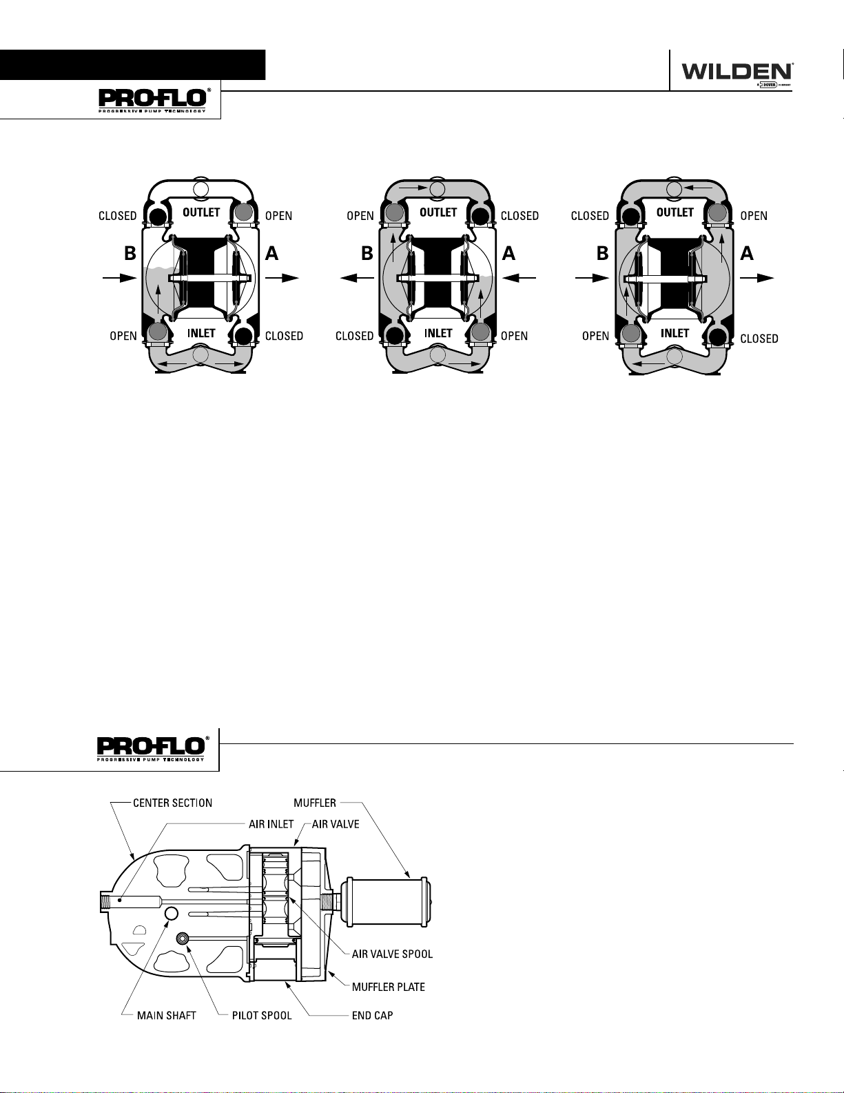
The Wilden diaphragm pump is an air-operated, positive displacement, self-priming pump. These drawings show fl ow pattern
through the pump upon its initial stroke. It is assumed the pump has no fl uid in it prior to its initial stroke.
FIGURE 1 The air valve dir ects pre ssurized
air to the back side of diaphragm A. The
compressed air is applied directly to the
liquid column separated by elastomeric
diaphragms. The diaphragm acts as
a separation membrane between the
compressed air and liquid, balancing the
load and removing mechanical stress
from the diaphragm. The compressed
air moves the diaphragm away from
the center of the pump. The opposite
diaphragm is pulled in by the shaft
connected to the pressurized diaphragm.
Diaphragm B is on its suction stroke; air
behind the diaphragm has been forced
out to atmosphere through the exhaust
port of the pump. The movement of
diaphragm B toward the center of the
pump creates a vacuum within chamber B.
Atmospheric pressure forces fl uid into
the inlet manifold forcing the inlet valve
ball off its seat. Liquid is free to move
past the inlet valve ball and fi ll the liquid
chamber (see shaded area).
HOW IT WORKS—AIR DISTRIBUTION SYSTEM
FIGURE 2 When the pressurized diaphragm,
diaphr agm A, re ache s the limit of i ts dis charge
stroke, the air valve redirects pressurized
air to the back side of diaphragm B. The
pressurized air forces diaphragm B away
from the center while pulling diaphragm A
to the center. Diaphragm B is now on its
discharge stroke. Diaphragm B forces the
inlet valve ball onto its seat due to the
hydraulic forces developed in the liquid
chamber and manifold of the pump. These
same hydraulic forces lift the discharge
valve ball off its seat, while the opposite
discharge valve ball is forced onto its seat,
forcing fl uid to fl ow through the pump
discharge. The movement of diaphragm A
toward the center of the pump creates a
vacuum within liquid chamber A. Atmospheric pressure forces fl uid into the inlet
manifold of the pump. The inlet valve ball
is f or ce d of f it s seat a ll owing th e fl uid being
pumped to fi ll the liquid chamber.
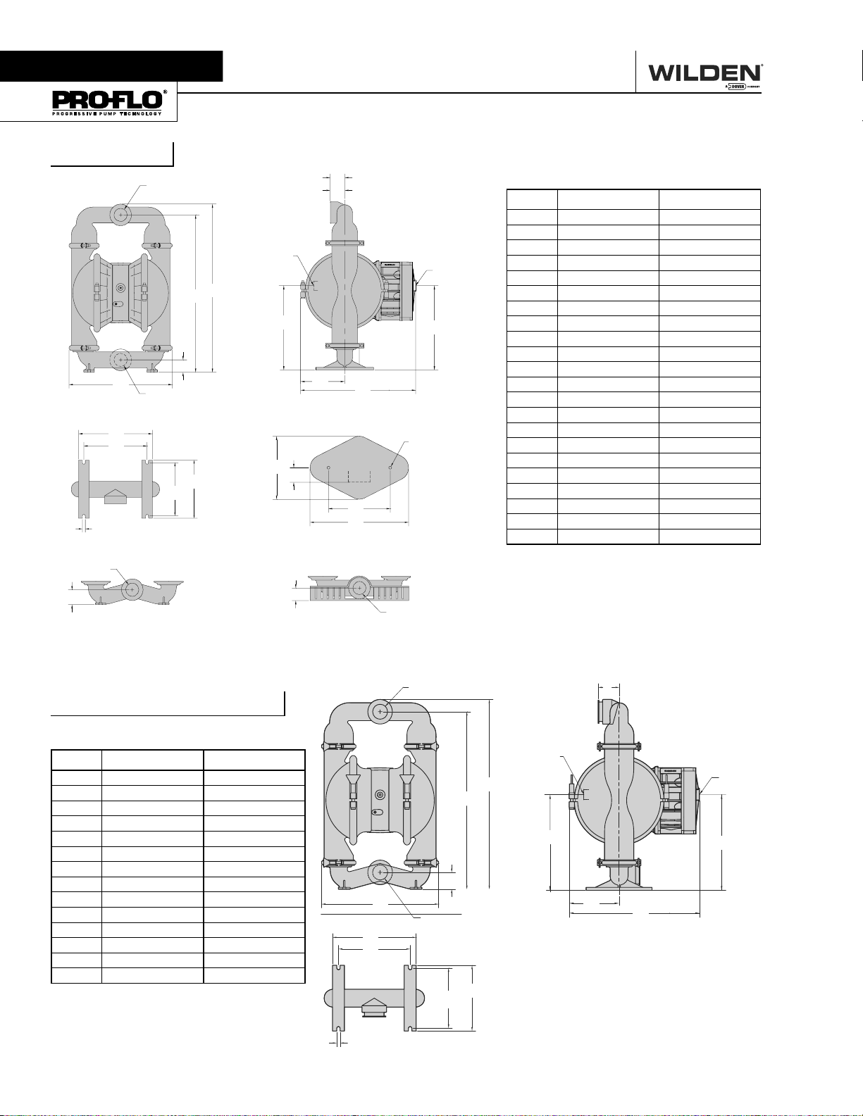
The Pro-Flo
moving parts : the air valve spool and the pilot spool. The heart of
the system is the air valve spool and air valve. This valve design
incorporates an unbalanced spool. The smaller end of the spool
is pressurized continuously, while the large end is alternately
pressurized then exhausted to move the spool. The spool directs
pressurized air to one air chamber while exhausting the other.
The air causes the main shaft /diaphragm assembly to shift to
one side — discharging liquid on that side and pulling liquid in
on the other side. When the shaft reaches the end of its stroke,
the inner piston actuates the pilot spool, which pressurizes and
exhausts the large end of the air valve spool. The repositioning
of the air valve spool routes the air to the other air chamber.
®
patented air distribution system incorporates two
FIGURE 3 At completion of the stroke,
the air valve again redirects air to the
back side of diaphragm A, which starts
diaphragm B on its exhaust stroke. As
the pump reaches its original starting
point, each diaphragm has gone through
one exhaust and one discharge stroke.
This constitutes one complete pumping
cycle. The pump may take several cycles
to completely prime depending on the
conditions of the application.
WIL-10110-E-02 8/06 3 WILDEN PUMP & ENGINEERING, LLC
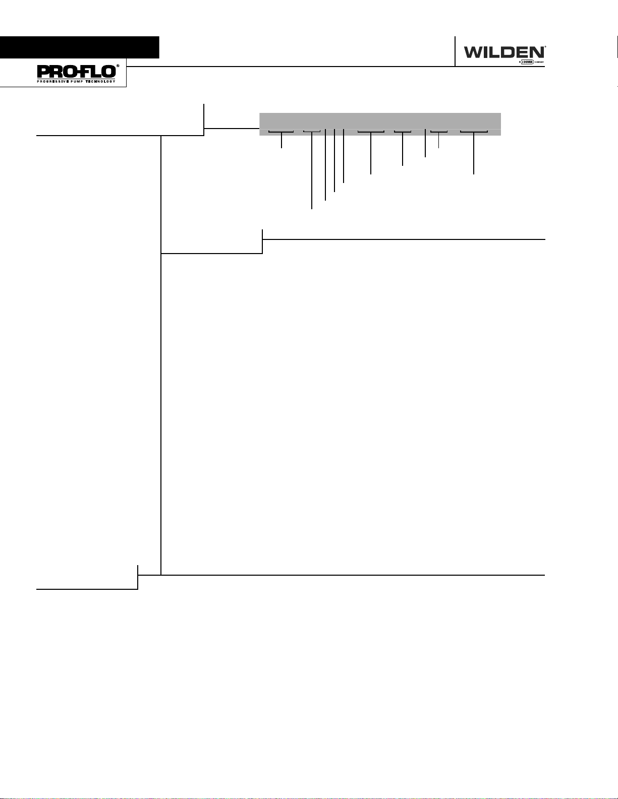
Section 4
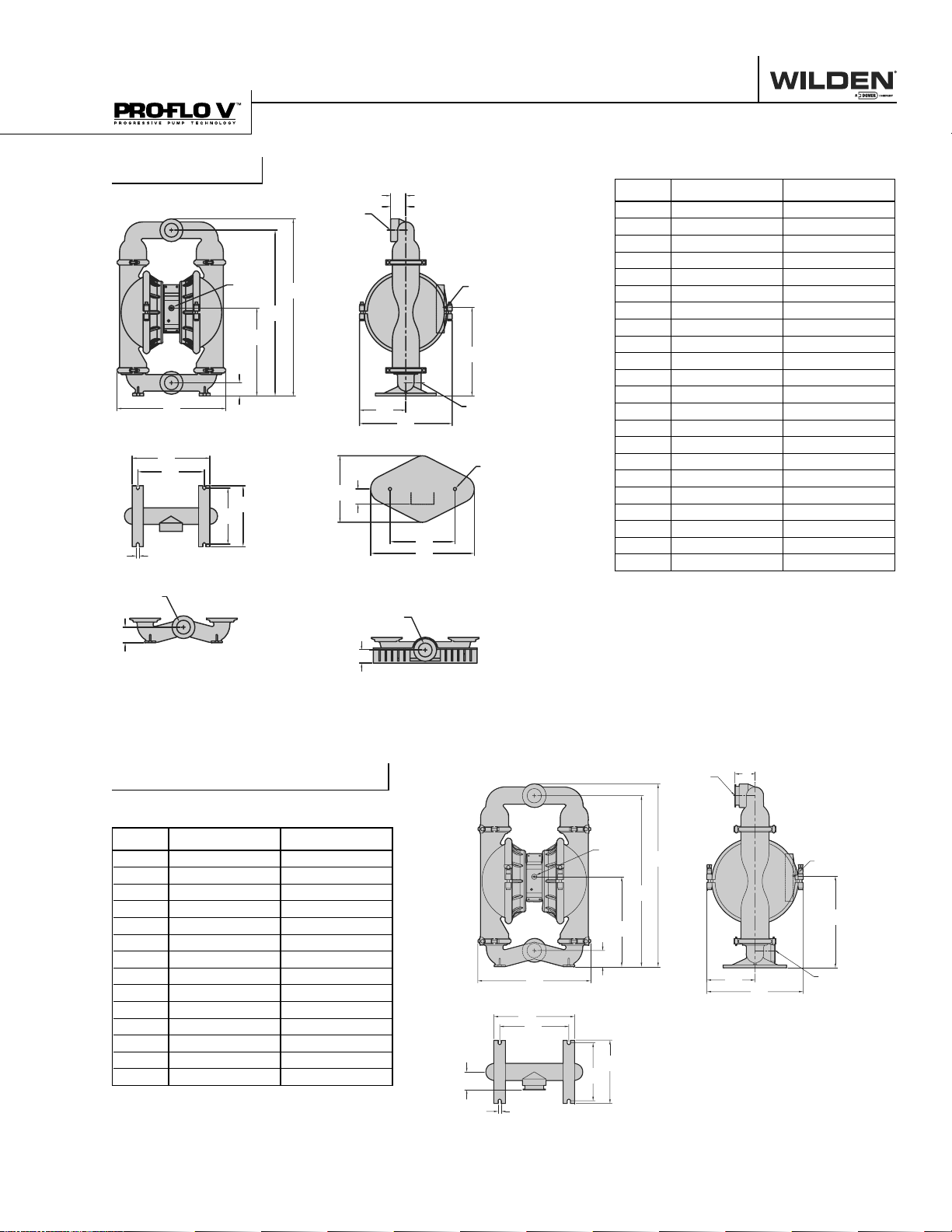
P15 Metal
76 mm
(3") FNPT
LIQUID DISCHARGE
B
A
76 mm
(3") FNPT
LIQUID INLET
L
M
N
R
76 mm
(3") FNPT
LIQ UID INLE T
S
FOO TED BASE FOR S TAINLE SS
STEEL & A LLOY C MO DEL S
CALL 1-800-577-8111 FOR SALES AND SUPPORT
DIMENSIONAL DRAWINGS
F - 316 S. S., C.I., AL LOY C
G - ALUM.
19 mm
(3/4") FNPT
AIR INLET
D
C
E
J
U
P
V
ALUMINUM BASE SCREEN
T
W
X
K
76 mm
(3") FNPT
LIQUID INLET
25 mm (1")
FNPT AIR
EXHAUST
H
Y
DIMENSIONS
ITEM METRIC (mm) STANDARD (inch)
A505 19.9
B58 2.3
C762 30.0
D823 32.4
E391 15.4
F71 2.8
G69 2.7
H406 16.0
J165 6.5
K523 20.6
L361 14.2
M305 12.0
N259 10.2
P282 11.1
R15 0.6
S71 2.8
T66 2.6
U305 12.0
V43 1.7
W305 12.0
X478 18.8
Y15 0.6
P15 Metal Saniflo
FDA
DIMENSIONS
ITEM METRIC (mm) STANDARD (inch)
A521 20.5
B71 2.8
C767 30.2
D810 31.9
E391 15.4
F89 3.5
G216 8.5
H406 16.0
J523 20.6
K356 14.0
L305 12.0
M257 10.1
N279 11.0
P15 0.6
76 mm ( 3")
TRI-CLAMP
LIQUID DISCHARGE
19 mm (3/ 4")
NPT FEMA LE
AIR INLE T
D
C
E
B
A
76 mm ( 3")
K
L
P
TRI-CLAMP
LIQUID INLET
N
M
F
25 mm (1")
FNPT AIR
EXHAUST
H
G
J
WILDEN PUMP & ENGINEERING, LLC 4 WIL-10110-E-02 8/06
CALL 1-800-577-8111 FOR SALES AND SUPPORT
DIMENSIONAL DRAWINGS
PV15 Metal
A
L
M
R
76 mm ( 3") F NPT
LIQUID INLET
S
FOOTED BASE FOR STAINLESS
STEEL & A LLOY C MO DEL S
N
19 mm
(3/4")
FNPT
AIR
INLET
C
B
P
E
D
76 mm (3")
FNPT LIQUID
DISCHARGE
U
V
ALUMINUM BASE SCREEN
76 mm ( 3") F NPT
LIQUID INLET
T
F - 316 S. S., C.I., AL LOY C
G - ALUM.
J
K
W
X
25 mm (1")
FNP T AIR
EXHAUST
H
76 mm ( 3") F NPT
LIQUID INLET
Y
DIMENSIONS
ITEM METRIC (mm) STANDARD (inch)
A505 19.9
B58 2.3
C386 15.2
D762 30.0
E823 32.4
F71 2.8
G84 3.3
H389 15.3
J216 8.5
K406 16.0
L363 14.3
M307 12.1
N257 10.1
P282 11.1
R15 0.6
S71 2.8
T66 2.6
U305 12.0
V43 1.7
W305 12.0
X478 18.8
Y 15 DIA. .6 DIA.
76 mm (3")
PV15 Metal Saniflo
FDA
DIMENSIONS
ITEM METRIC (mm) STANDARD (inch)
A521 20.5
19 mm
(3/4")
FNPT
AIR INLE T
TRI-CLAMP
LIQUID DISCHARGE
E
F
25 mm (1")
FNP T AIR
EXHAUST
B71 2.8
C396 15.6
D767 30.2
E810 31.9
D
C
H
F89 3.5
G216 8.5
H406 16.0
J424 16.7
K356 14.0
L305 12.0
A
K
L
B
G
J
76 mm ( 3")
TRI-CLAMP
LIQUID INLET
M257 10.1
N279 11.0
P15 0.6
WIL-10110-E-02 8/06 5 WILDEN PUMP & ENGINEERING, LLC
F
P
N
M
Section 5A
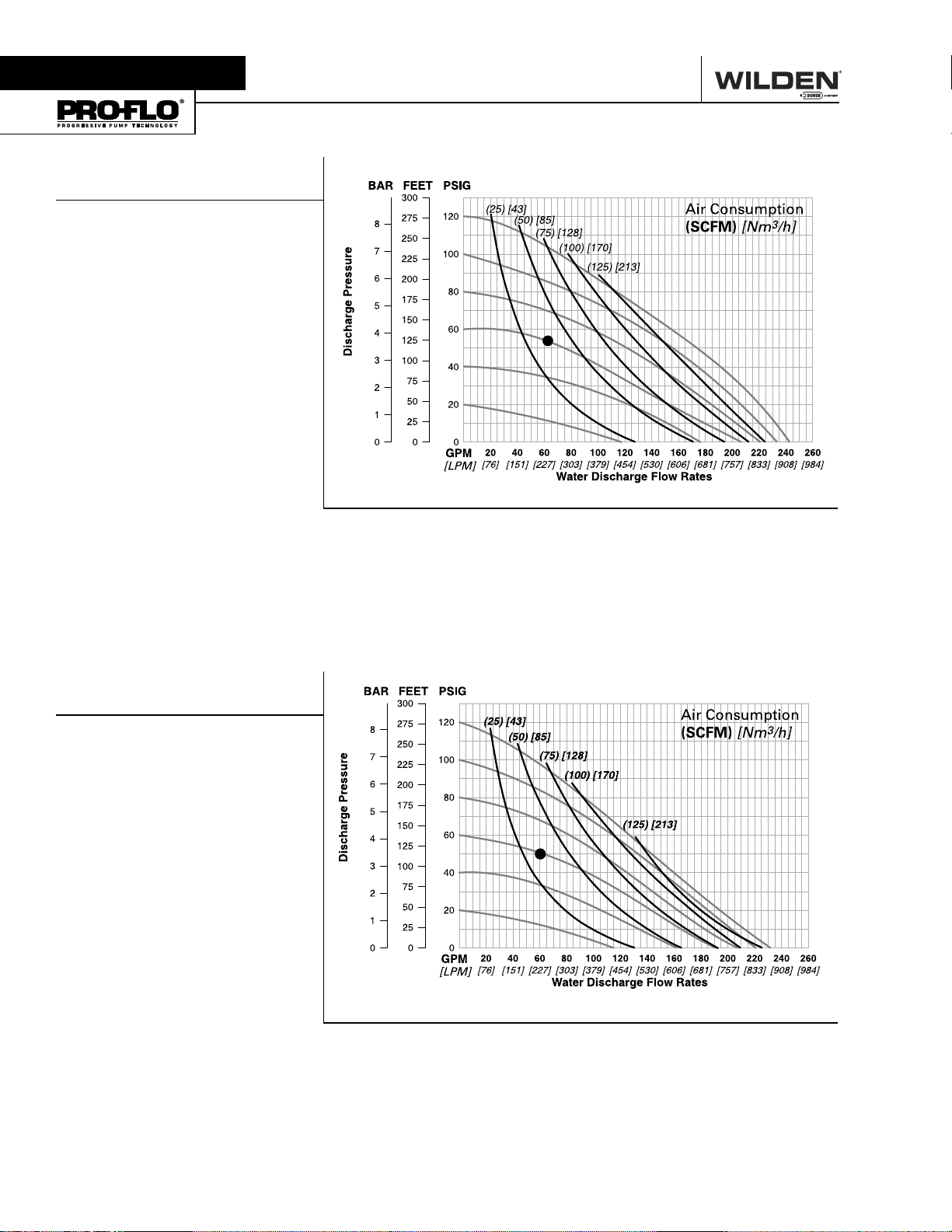
P15 performance Curves
P15 METAL
RUBBER-FITTED
Height .................................823 mm (32.4")
Width .................................. 505 mm (19.9")
Depth ..................................523 mm (20.6")
Est. Ship Weight ...Aluminum 60 kg (132 lbs)
316 Stainless Steel 90 kg (198 lbs)
Cast Iron 98 kg (216 lbs)
Alloy C 112 kg (246 lbs)
Air Inlet ................................... 19 mm (3⁄4")
Inlet ............................................ 76 mm (3")
Outlet ......................................... 76 mm (3")
Suction Lift ......................6.7 m Dry (22.1')
9.3 m Wet (30.6')
Displacement/Stroke ......5.61 l (1.48 gal.)
Max. Flow Rate ........... 920 lpm (243 gpm)
Max. Size Solids ...................9.5 mm (3⁄8")
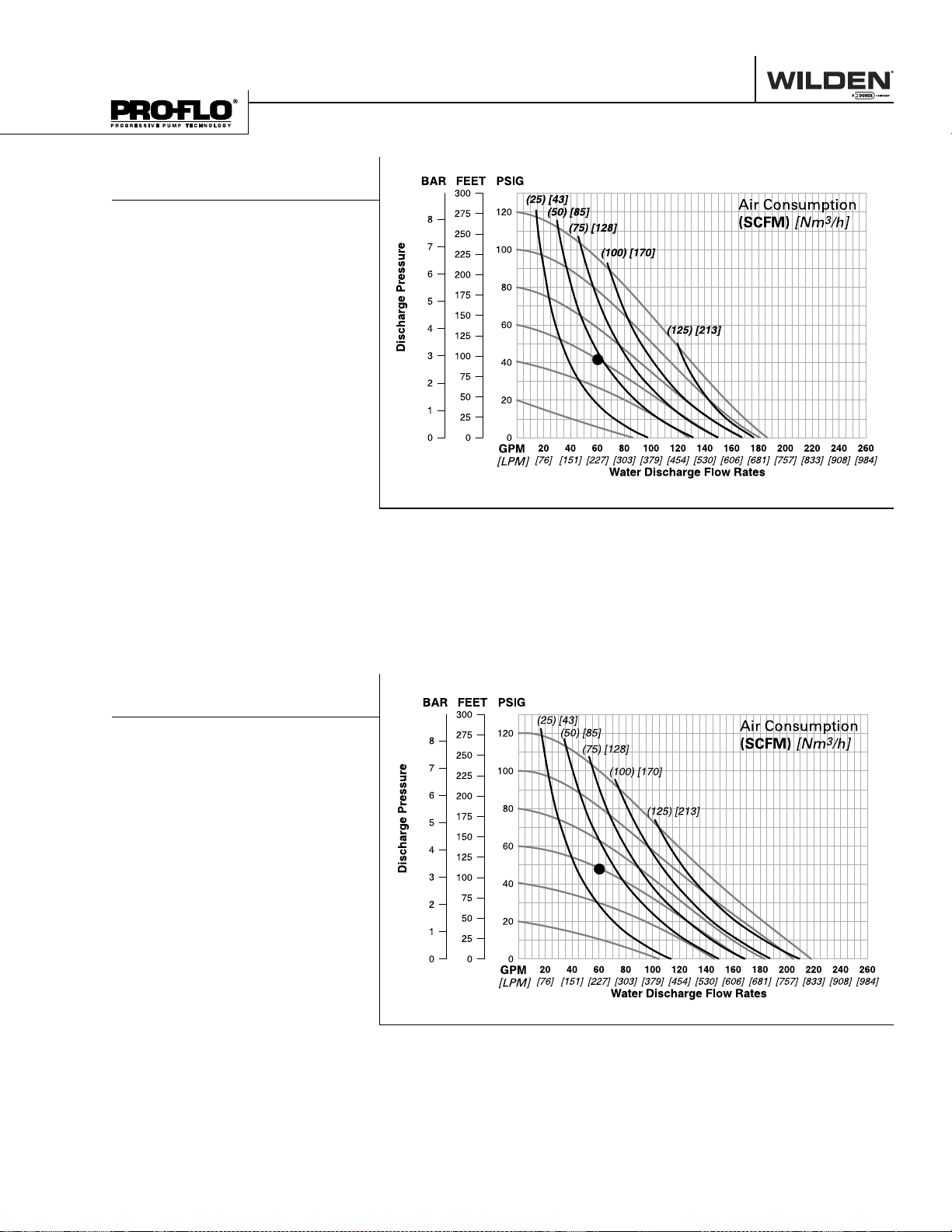
1
Displacement per stroke was calculated
at 4.8 bar (70 psig) air inlet pressure
against a 2.1 bar (30 psig) head pressure.
Example: To pump 227 lpm (60 gpm)
against a discharge head of 3.7 bar
(54 psig) requires 4.1 bar (60 psig) and
3
61 Nm
/h (36 scfm) air consumption.
Caution: Do not exceed 8.6 bar (125 psig)
air supply pressure.
CALL 1-800-577-8111 FOR SALES AND SUPPORT
PERFORMANCE
1
Flow rates indicated on chart were determined by pumping water.
For optimum life and performance, pumps should be specifi ed so that daily operation
parameters will fall in the center of the pump performance curve.
P15 METAL
TPE-FITTED
Height .................................823 mm (32.4")
Width .................................. 505 mm (19.9")
Depth ..................................523 mm (20.6")
Est. Ship Weight ...Aluminum 60 kg (132 lbs)
316 Stainless Steel 90 kg (198 lbs)
Cast Iron 98 kg (216 lbs)
Alloy C 112 kg (246 lbs)
Air Inlet ................................... 19 mm (3⁄4")
Inlet ............................................ 76 mm (3")
Outlet ......................................... 76 mm (3")
Suction Lift ..................... 6.9 m Dry (22.7')
9.2 m Wet (29.5')
Displacement/Stroke ........ 5.7 l (1.49 gal.)
Max. Flow Rate ............878 lpm (232 gpm)
Max. Size Solids ...................9.5 mm (3⁄8")
1
Displacement per stroke was calculated
at 4.8 bar (70 psig) air inlet pressure
against a 2.1 bar (30 psig) head pressure.
Example: To pump 227 lpm (60 gpm)
against a discharge pressure head of 3.4
bar (50 psig) requires 4.1 bar (60 psig) and
3
58 Nm
/h (34 scfm) air consumption.
Caution: Do not exceed 8.6 bar (125 psig)
air supply pressure.
1
Flow rates indicated on chart were determined by pumping water.
For optimum life and performance, pumps should be specifi ed so that daily operation
parameters will fall in the center of the pump performance curve.
WILDEN PUMP & ENGINEERING, LLC 6 WIL-10110-E-02 8/ 06
CALL 1-800-577-8111 FOR SALES AND SUPPORT
PERFORMANCE
P15 METAL
PTFE-FITTED
Height .................................823 mm (32.4")
Width .................................. 505 mm (19.9")
Depth ..................................523 mm (20.6")
Est. Ship Weight ...Aluminum 60 kg (132 lbs)
316 Stainless Steel 90 kg (198 lbs)
Cast Iron 98 kg (216 lbs)
Alloy C 112 kg (246 lbs)
Air Inlet ................................... 19 mm (3⁄4")
Inlet ............................................ 76 mm (3")
Outlet ......................................... 76 mm (3")
Suction Lift ......................4.8 m Dry (15.9')
9.0 m Wet (29.5')
Displacement/Stroke ....... 3.6 l (0.95 gal.)
Max. Flow Rate ............ 708 lpm (187 gpm)
Max. Size Solids ...................9.5 mm (3⁄8")
1
Displacement per stroke was calculated
at 4.8 bar (70 psig) air inlet pressure
against a 2.1 bar (30 psig) head pressure.
Example: To pump 227 lpm (60 gpm)
against a discharge pressure head of 2.9
bar (42 psig) requires 4.1 bar (60 psig) and
3
80 Nm
/h (47 scfm) air consumption.
Caution: Do not exceed 8.6 bar (125 psig)
air supply pressure.
1
Flow rates indicated on chart were determined by pumping water.
For optimum life and performance, pumps should be specifi ed so that daily operation
parameters will fall in the center of the pump performance curve.
P15 METAL
ULTRA-FLEX™-FITTED
Height .................................823 mm (32.4")
Width .................................. 505 mm (19.9")
Depth ..................................523 mm (20.6")
Est. Ship Weight ...Aluminum 60 kg (132 lbs)
316 Stainless Steel 80 kg (198 lbs)
Cast Iron 98 kg (216 lbs)
Alloy C 112 kg (246 lbs)
Air Inlet ................................... 19 mm (3⁄4")
Inlet ............................................ 76 mm (3")
Outlet ......................................... 76 mm (3")
Suction Lift ......................8.0 m Dry (26.1')
9.2 m Wet (30.1')
Displacement/Stroke ......4.62 l (1.22 gal.)
Max. Flow Rate ............ 825 lpm (218 gpm)
Max. Size Solids ...................9.5 mm (3⁄8")
1
Displacement per stroke was calculated
at 4.8 bar (70 psig) air inlet pressure
against a 2.1 bar (30 psig) head pressure.
Example: To pump 227 lpm (60 gpm)
against a discharge pressure head of 3.3
bar (48 psig) requires 4.1 bar (60 psig) and
3
68 Nm
/h (40 scfm) air consumption.
Caution: Do not exceed 8.6 bar (125 psig)
air supply pressure.
1
Flow rates indicated on chart were determined by pumping water.
For optimum life and performance, pumps should be specifi ed so that daily operation
parameters will fall in the center of the pump performance curve.
WIL-10110-E-02 8/06 7 WILDEN PUMP & ENGINEERING, LLC
PV15 performance Curves
PV15 METAL
RUBBER-FITTED
Height .................................823 mm (32.4")
Width .................................. 505 mm (19.9")
Depth .................................. 406 mm (16.0")
Est. Ship Weight ... Aluminum 55 kg (121 lbs)
316 Stainless Steel 85 kg (187 lbs)
Cast Iron 93 kg (205 lbs)
Alloy C 107 kg (235 lbs)
Air Inlet ................................... 19 mm (3⁄4")
Inlet ............................................ 76 mm (3")
Outlet ......................................... 76 mm (3")
Suction Lift ......................6.6 m Dry (21.6')
9.3 m Wet (30.6')
Displacement/Stroke ......5.53 l (1.46 gal.)
Max. Flow Rate ........... 909 lpm (240 gpm)
Max. Size Solids ...................9.5 mm (3⁄8")
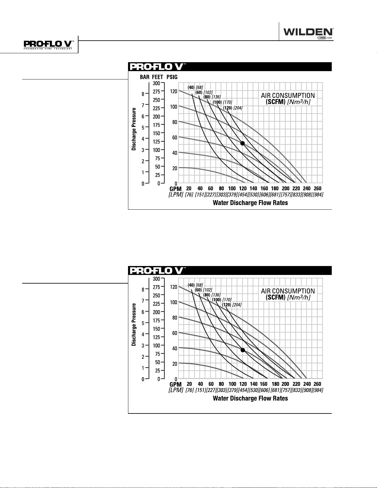
1
Displacement per stroke was calculated
at 4.8 bar (70 psig) air inlet pressure
against a 2.1 bar (30 psig) head pressure.
Example: To pump 454 lpm (120 gpm)
against a discharge head of 3.6 bar
(52 psig) requires 5.5 bar (80 psig) and
3
170 Nm
Caution: Do not exceed 8.6 bar (125 psig)
air supply pressure.
/h (100 scfm) air consumption.
CALL 1-800-577-8111 FOR SALES AND SUPPORT
PERFORMANCE
1
Flow rates indicated on chart were determined by pumping water.
For optimum life and performance, pumps should be specifi ed so that daily operation
parameters will fall in the center of the pump performance curve.
PV15 METAL
TPE-FITTED
Height .................................823 mm (32.4")
Width .................................. 505 mm (19.9")
Depth .................................. 406 mm (16.0")
Est. Ship Weight ... Aluminum 55 kg (121 lbs)
316 Stainless Steel 85 kg (187 lbs)
Cast Iron 93 kg (205 lbs)
Alloy C 107 kg (235 lbs)
Air Inlet ................................... 19 mm (3⁄4")
Inlet ............................................ 76 mm (3")
Outlet ......................................... 76 mm (3")
Suction Lift ......................7.6 m Dry (25.0')
9.5 m Wet (31.2')
Displacement/Stroke ...... 5.72 l (1.51 gal.)
Max. Flow Rate ........... 906 lpm (239 gpm)
Max. Size Solids ...................9.5 mm (3⁄8")
1
Displacement per stroke was calculated
at 4.8 bar (70 psig) air inlet pressure
against a 2.1 bar (30 psig) head pressure.
Example: To pump 254 lpm (120 gpm)
against a discharge pressure head of
2.6 bar (38 psig) requires 4.1 bar (60
psig) and 136 Nm
consumption.
Caution: Do not exceed 8.6 bar (125 psig)
air supply pressure.
3
/h (80 scfm) air
1
Flow rates indicated on chart were determined by pumping water.
For optimum life and performance, pumps should be specifi ed so that daily operation
parameters will fall in the center of the pump performance curve.
WILDEN PUMP & ENGINEERING, LLC 8 WIL-10110-E-02 8/06
CALL 1-800-577-8111 FOR SALES AND SUPPORT
PERFORMANCE
PV15 METAL
PTFE-FITTED
Height .................................823 mm (32.4")
Width .................................. 505 mm (19.9")
Depth .................................. 406 mm (16.0")
Est. Ship Weight ... Aluminum 55 kg (121 lbs)
316 Stainless Steel 85 kg (187 lbs)
Cast Iron 93 kg (205 lbs)
Alloy C 107 kg (235 lbs)
Air Inlet ................................... 19 mm (3⁄4")
Inlet ............................................ 76 mm (3")
Outlet ......................................... 76 mm (3")
Suction Lift ......................5.0 m Dry (16.5')
9.5 m Wet (31.2')
Displacement/Stroke ..... 3.48 l (0.92 gal.)
Max. Flow Rate ............ 704 lpm (186 gpm)
Max. Size Solids ...................9.5 mm (3⁄8")
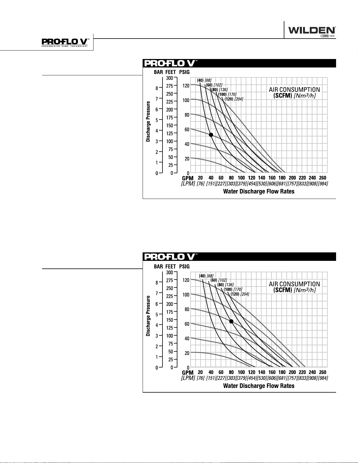
1
Displacement per stroke was calculated
at 4.8 bar (70 psig) air inlet pressure
against a 2.1 bar (30 psig) head pressure.
Example: To pump 151 lpm (40 gpm)
against a discharge pressure head of
3.5 bar ( 51 psig) requires 4.1 bar (60 psig)
and 68 Nm
Caution: Do not exceed 8.6 bar (125 psig)
air supply pressure.
3
/h (40 scfm) air consumption.
1
Flow rates indicated on chart were determined by pumping water.
For optimum life and performance, pumps should be specifi ed so that daily operation
parameters will fall in the center of the pump performance curve.
PV15 METAL
ULTRA-FLEX™-FITTED
Height .................................823 mm (32.4")
Width .................................. 505 mm (19.9")
Depth .................................. 406 mm (16.0")
Est. Ship Weight ... Aluminum 55 kg (121 lbs)
316 Stainless Steel 85 kg (187 lbs)
Cast Iron 93 kg (205 lbs)
Alloy C 107 kg (235 lbs)
Air Inlet ................................... 19 mm (3⁄4")
Inlet ............................................ 76 mm (3")
Outlet ......................................... 76 mm (3")
Suction Lift ......................6.1 m Dry (20.0')
9.5 m Wet (31.2')
Displacement/Stroke ......4.69 l (1.24 gal.)
Max. Flow Rate ........... 854 lpm (226 gpm)
Max. Size Solids ...................9.5 mm (3⁄8")
1
Displacement per stroke was calculated
at 4.8 bar (70 psig) air inlet pressure
against a 2.1 bar (30 psig) head pressure.
Example: To pump 303 lpm (80 gpm)
against a discharge pressure head of
4.3 bar (62 psig) requires 5.5 bar
(80 psig) and 136 Nm
consumption.
Caution: Do not exceed 8.6 bar (125 psig)
air supply pressure.
3
/h (80 scfm) air
1
Flow rates indicated on chart were determined by pumping water.
For optimum life and performance, pumps should be specifi ed so that daily operation
parameters will fall in the center of the pump performance curve.
WIL-10110-E-02 8/06 9 WILDEN PUMP & ENGINEERING, LLC
 Loading...