

Wilden PS Stallion Series Manual
EOM
Engineering
Operation &
Maintenance
PS Stallion
Original™ Metal Pump
Where Innovation Flows
wildenpump.com
TABLE OF CONTENTS
SECTION 1 CAUTIONS—READ FIRST! ..............................................1
SECTION 2 WILDEN PUMP DESIGNATION SYSTEM .................................2
SECTION 3 HOW IT WORKS—PUMP & AIR DISTRIBUTION SYSTEM ................ 3
SECTION 4 DIMENSIONAL DRAWINGS .............................................4
SECTION 5 PERFORMANCE
PS Stallion Performance
Performance Curves
PS4 - EZ-Install TPE-Fitted .............................................. 6
PS8 - EZ-Install TPE-Fitted .............................................. 6
PS15 - EZ-Install TPE-Fitted ............................................. 7
Suction-Lift Curves ......................................................8
SECTION 6 SUGGESTED INSTALLATION, OPERATION & TROUBLESHOOTING ....... 11
SECTION 7 DISASSEMBLY / REASSEMBLY ........................................ 14
Air Valve/Center Section Disassembly .......................................17
Reassembly Hints & Tips ..................................................21
SECTION 8 EXPLODED VIEW & PARTS LISTING
PS4 Stallion Metal .......................................................22
PS8 Stallion Metal .......................................................24
PS15 Stallion Metal ......................................................26
SECTION 9 ELASTOMER OPTIONS .................................................28
Section 1
CAUTIONS—READ FIRST!
CAUTION: Do not apply compressed air to the
exhaust port — pump will not function.
CAUTION: Do not over-lubricate air supply —
excess lub rication will reduce pump performance.
Pump is pre-lubed.
TEMPERATURE LIMITS:
Polypropylene 0°C to 79°C 32°F to 175°F
PVDF –12°C to 107°C 10°F to 225°F
PFA 7°C to 107°C 45°F to 225°F
Neoprene –18°C to 93°C 0°F to 200°F
Buna-N –12°C to 82°C 10°F to 180°F
EPDM –51°C to 138°C –60°F to 280°F
Viton
®
FKM –40°C to 177°C –40°F to 350°F
Wil-Flex™ –40°C to 107°C –40°F to 225°F
Saniflex™ –29°C to 104°C –20°F to 220°F
Polyurethane –12°C to 66°C 10°F to 150°F
Polytetrafluoroethylene (PTFE)1 4°C to 104°C 40°F to 220°F
Nordel
®
EPDM –51°C to 138°C 60°F to 280°F
Nylon –18°C to 93°C 0°F to 200°F
Acetal –29°C to 82°C –20°F to 180°F
SIPD PTFE
SIPD PTFE
Geolast
with
Neoprene-backed
with
EPDM-backed 4°C to 138°C 40°F to 280°F
®
–40°C to 82°C –40°F to 180°F
1
4°C to 149°C (40°F to 300°F) - 13 mm (1/2") and 25 mm (1") models only.
–18°C to 93°C 0°F to 200°F
NOTE: Not all materials are available for all
models. Refer to Section 2 for the material
options available for your pump.
CAUTION: When choosing pump materials, be
sure to check the temperature limits for all wetted
components. Example: Viton® has a maximum
limit of 177°C (350°F), but polypropylene has a
maximum limit of only 79°C (175°F).
CAUTION: Maximum temperature limits are
based upon mechanical stress only. Certain
chemicals will significantly reduce maximum
safe operating temperatures. Consult Chemical
Resistance Guide for chemical compatibility and
temperature limits.
WARNING: Prevent static sparking — If static
sparking occurs, fire or explosion could result.
Pump, valves and containers must be grounded
to a proper grounding point when handling
flammable fluids and whenever discharge of
static electricity is a hazard.
CAUTION: Do not exceed 8.6 bar (125 psig) air
supply pressure.
CAUTION: The process fluid and cleaning fluids
must be chemically compatible with all wetted
pump components. Consult Chemical Resistance
Guide.
CAUTION: Do not exceed 82°C (180°F) air inlet
temperature for Pro-Flo
®
SHIFT models.
CAUTION: Pumps should be thoroughly flushed
before installing into process lines. FDA- and
USDA-approved pumps should be cleaned and/
or sanitized before being used.
CAUTION: Always wear safety glasses when
operating pump. If diaphragm rupture occurs,
material being pumped may be forced out air
exhaust.
CAUTION: Before any maintenance or repair is
attempted, the compressed air line to the pump
should be disconnected and all air pressure
allowed to bleed from pump. Disconnect all
intake, discharge and air lines. Drain the pump
by turning it upside down and allowing any fluid
to flow into a suitable container.
CAUTION: Blow out air line for 10 to 20 seconds
before attaching to pump to make sure all pipeline
debris is clear. Use an in-line air filter. A 5µ
(micron) air filter is recommended.
NOTE: Before starting disassembly, mark a line
from each liquid chamber to its corresponding air
chamber. This line will assist in proper alignment
during reassembly.
CAUTION: Pro-Flo® pumps cannot be used
in submersible applications. Pro-Flo® SHIFT
is available in both submersible and nonsubmersible options. Do not use non-submersible
Pro-Flo® SHIFT models in submersible
applications. Tur b o-Flo® pumps can also be used
in submersible applications.
CAUTION : Tighten all hardware prior to installation.
WIL-10830-E-02 1 WILDEN PUMP & ENGINEERING, LLC
Section 2
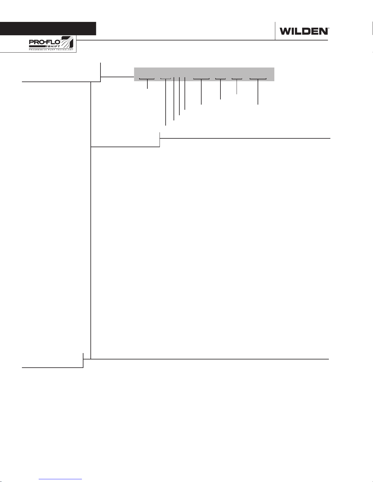
WILDEN PUMP DESIGNATION SYSTEM
PS STALLION
51 mm (2") Pump
Maximum Flow
Rate:
675 LPM (178
GPM)
LEGEND
XXX / XXXX X / XXX / XX / XX / XXXX
MODEL SEAT
MATERIAL CODES
MODEL
PS4 = 38 mm (1-1/2”)
PS8 = 51 mm (2”)
PS15 = 76 mm (3”)
WETTED PARTS & OUTER PISTON
AA = ALUMINUM / ALUMINUM
WW = DUCTILE IRON / DUCTILE
IRON (PS4 & PS 8 Only)
AIR CHAMBERS
A = ALUMINUM
CENTER BLOCK
A = ALUMINUM
DIAPHRAGMS
AIR VALVE
CENTER BLOCK
AIR CHAMBERS
WETTED PARTS & OUTER PISTON
AIR VALVE
R = ANODIZED ALUMINUM
DIAPHRAGMS
FWS = SANITARY WIL-FLEX™,
EZ-INSTALL [Santoprene®
(Two Orange Dots)]
ZGS = GEOLAST®, EZ-INSTALL
ZPS = POLYURETHANE,
EZ-INSTALL (Clear)
ZSS = SANIFLEX™, EZ-INSTALL
(Cream)
ZWS = WIL-FLEX™, EZ-INSTALL
(Orange Dot)
VALVE
VALVE BALLS
SPECIALTY
CODE
(if applicable)
VALVE BALL
BN = BUNA-N (Red Dot)
EP = NORDEL® (Blue Dot)
FS = SANIFL EX™ [Hytrel®
(Cream)]
F W = SANI TARY WIL-FLEX ™
[Santoprene® (Two Orange
Dots)]
NE = NEOPRENE (Green Dot)
PU = Polyurethane (Brown)
VT = VITON® (Silver or
White Dot)
WF = WIL-FLE X™ [Santoprene®
(Orange Dot)]
VALVE SEAT
BN = BUNA-N (Red Dot)
EP = NORDEL® (Blue Dot)
FS = SANIFL EX™ [Hytrel®
(Cream)]
NE = NEOPRENE (Green Dot)
PU = Polyurethane (Clear)
VT = VITON® (Silver or
White Dot)
WF = WIL-FLE X™ [Santoprene®
(Orange Dot)]
SPECIALTY CODES
0046 Stallion internals, BSPT
0048 Stallion Internals
0050 Stallion
0051 Stallion, BSPT
0076 Food Processing, Stallion Internals
NOTE: Bold specialty codes indicate the standard product offering.
WILDEN PUMP & ENGINEERING, LLC 2 WIL-10830-E-02
Section 1
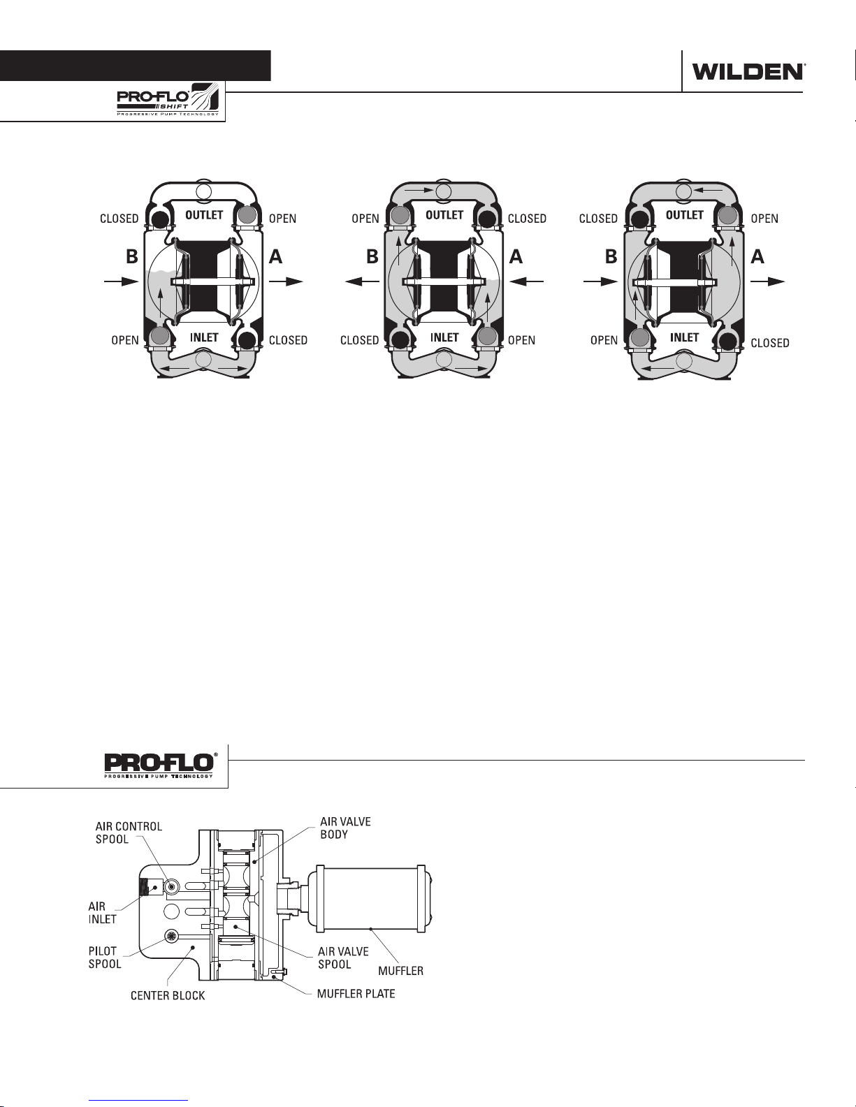
HOW IT WORKS—PUMP
The Wilden diaphragm pump is an air-operated, positive displacement, self-priming pump. These drawings show flow pattern
through the pump upon its initial stroke. It is assumed the pump has no fluid in it prior to its initial stroke.
FIGUR E 1 The air valve dire cts pre ssurized
air to the back side of diaphragm A. The
compressed air is applied directly to the
liquid column separated by elastomeric
diaphragms. The diaphragm acts as
a separation membrane between the
compressed air and liquid; a balanced
load removes mechanical stress from the
diaphragm. The compressed air moves
the diaphragm away from the center of
the pump. The opposite diaphragm is
pulled in by the shaf t connected to the
pressurized diaphragm. Diaphragm B
is on its suction stroke; air behind the
diaphragm has been forced out to the
atmosphere through the exhaust port of
the pump. The movement of diaphragm
B toward the center of the pump creates
a vacuum within chamber B. Atmospheric
pressure forces fluid into the inlet
manifold forcing the inlet valve ball off its
seat. Liquid is free to move past the inlet
valve ball and fill the liquid chamber (see
shaded area).
HOW IT WORKS—AIR DISTRIBUTION SYSTEM
FIGURE 2 When the pressurized diaphragm,
diaphra gm A, re aches t he limit of it s disc harge
stroke, the air valve redirects pressurized
air to the back side of diaphragm B. The
pressurized air forces diaphragm B away
from the center while pulling diaphragm A
to the center. Diaphragm B is now on its
discharge stroke. Diaphragm B forces the
inlet valve ball onto its seat due to the
hydraulic forces developed in the liquid
chamber and manifold of the pump. These
same hydraulic forces lif t the discharge
valve ball off its seat, while the opposite
discharge valve ball is forced onto its seat,
forcing fluid to flow through the pump
discharge. The movement of diaphragm A
toward the center of the pump creates a
vacuum within liquid chamber A. Atmospheric pressure forces fluid into the inlet
manifold of the pump. The inlet valve ball
is forced off its seat allowing the fluid being
pumped to fill the liquid chamber.
FIGURE 3 At completion of the stroke,
the air valve again redirects air to the
back side of diaphragm A, which starts
diaphragm B on its exhaust stroke. As
the pump reaches its original starting
point, each diaphragm has gone through
one exhaust and one discharge stroke.
This constitutes one complete pumping
cycle. The pump may take several cycles
to completely prime depending on the
conditions of the application.
WIL-10830-E-02 3 WILDEN PUMP & ENGINEERING, LLC
The heart of the patented Pro-Flo® SHIFT Air Distribution
System (ADS) is the air valve assembly. The air valve design
incorporates an unbalanced spool with the small end of the
spool being pressurized continuously while the large end of
the spool is alternately pressurized, then exhausted to move
the spool. The air valve spool directs pressurized air to one
chamber while exhausting the other. The air forces the main
shaft/diaphragm assembly to move to one side – discharging
liquid on that side and pulling liquid in on the other side. When
the shaft reaches the end of the stroke, the inner piston actuates
the pilot spool, which controls the air to the large end of the air
valve spool. The repositioning of the air valve spool routes the
air to the other air chamber. The air control spool allows air to
flow freely into the air chamber for the majorit y of each pump
stroke, but it significantly restricts the flow of air into the air
chamber when activated by the inner piston near the end of the
each stroke.
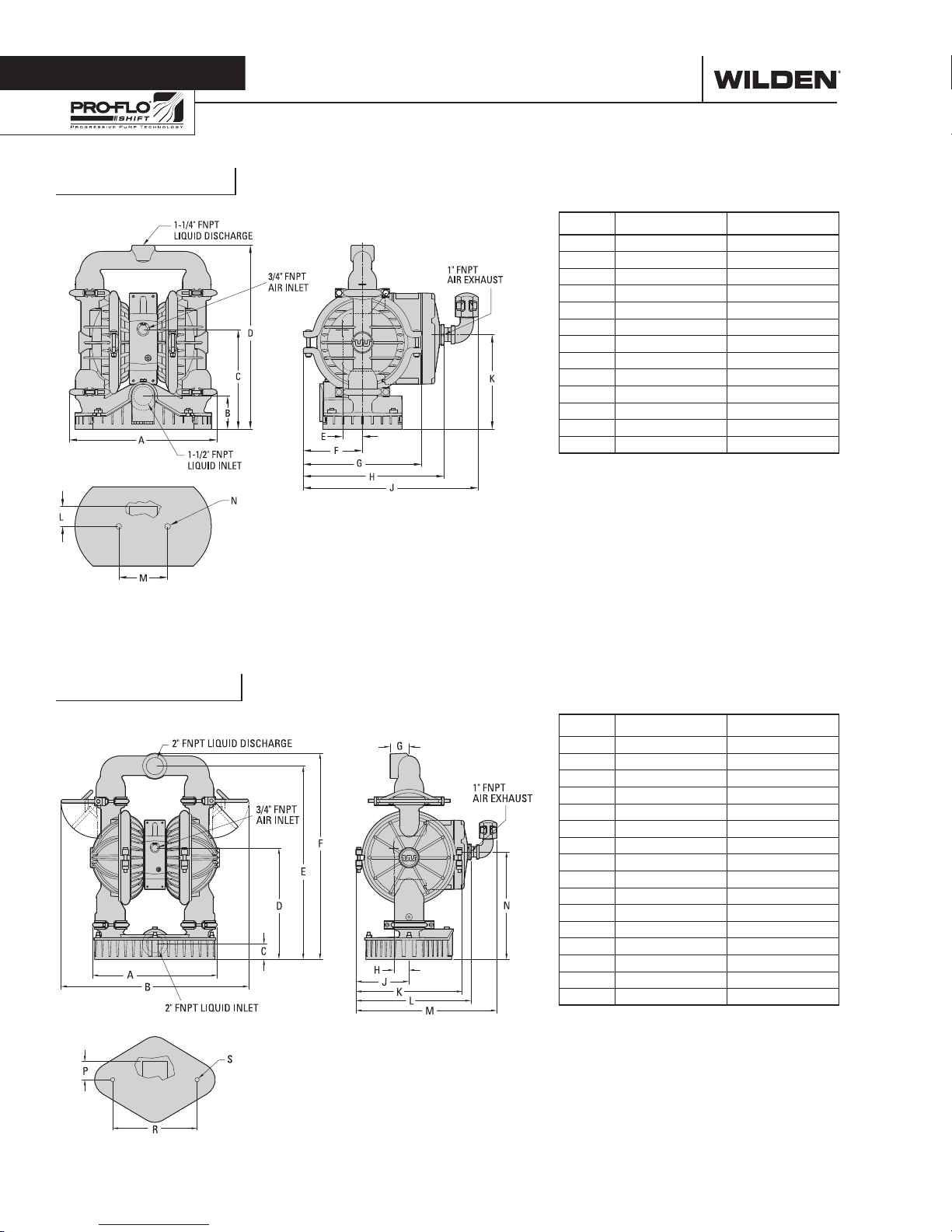
Section 4
PS4 Stallion
DIMENSIONAL DRAWINGS
DIMENSIONS
ITEM METRIC (mm) STANDARD (inch)
A 366 14.4
B 81 3.2
C 245 9.6
D 455 17.9
E 48 1.9
F 147 5.8
G 292 11.5
H 348 13.7
J 432 17.0
K 233 9.2
L 48 1.0
M 122 4.8
N 15 DIA. 0.6 DIA.
LW0261 REV. B
PS8 Stallion
DIMENSIONS
ITEM METRIC (mm) STANDARD (inch)
A 406 16.0
B 612 24.1
C 51 2.0
D 362 14.3
E 630 24.8
F 671 26.4
G 61 2.4
H 48 1.9
J 173 6.8
K 345 13.6
L 375 14.8
M 459 18.1
N 350 13.8
P 58 2.3
R 274 10.8
S 15 DIA. 0.6 DIA.
LW0262 REV. C
WILDEN PUMP & ENGINEERING, LLC 4 WIL-10830-E-02
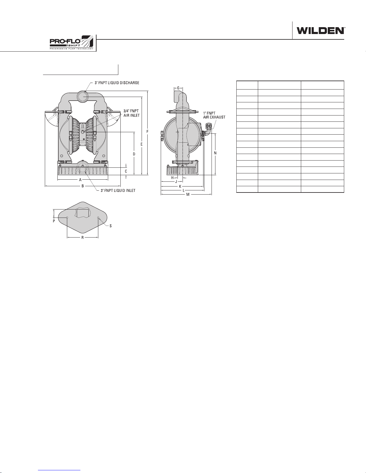
DIMENSIONAL DRAWINGS
PS15 Stallion
DIMENSIONS
ITEM METRIC (mm) STANDARD (inch)
A 495 19.5
B 742 29.2
C 74 2.9
D 422 16.6
E 770 30.3
F 828 32.6
G 84 3.3
H 48 1.9
J 213 8.4
K 414 16.3
L 424 16.7
M 498 19.6
N 409 16.1
P 84 3.3
R 305 12.0
S 15 DIA. 0.6 DIA.
LW0263 REV. B
WIL-10830-E-02 5 WILDEN PUMP & ENGINEERING, LLC
Section 5
PERFORMANCE
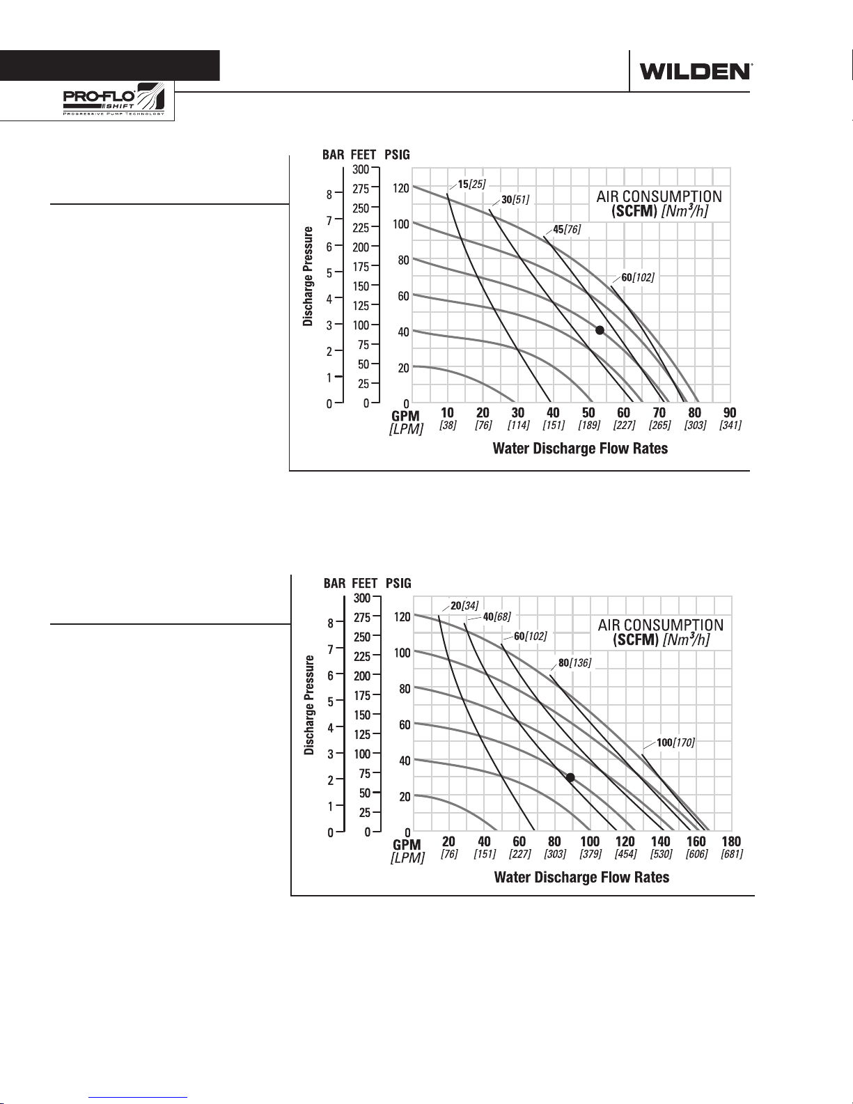
PS4 STALLION
EZ-INSTALL TPE-FITTED
Height ..................................455 mm (17.9”)
Width ..................................366 mm (14.4”)
Depth ...................................432 mm (17.0”)
Ship Weight .......... Aluminum 22 kg (49 lb)
Air Inlet ................................... 19 mm (3/4”)
Inlet ......................................38 mm (1-1/2”)
Outlet ...................................38 mm (1-1/2”)
Suction Lift ....................... 5.7 m Dry (18.7’)
9.0 m Wet (29.5’)
Disp. per Stroke ................. 0.8 L (0.22 gal)
Max. Flow Rate .............. 307 lpm (81 gpm)
Max. Size Solids .....................13 mm (1/2”)
1
Displacement per stroke was calculated at
4.8 bar (70 psig) air inlet pressure against a
2.1 bar (30 psig) head pressure.
Example: To pump 201 lpm (53 gpm)
against a discharge head of 2.8 bar
(40 psig) requires 5.5 bar (80 psig) and
3
66 Nm
/h (39 scfm) air consumption.
Caution: Do not exceed 8.6 bar (125 psig)
air supply pressure.
Ductile Iron 30 kg (66 lb)
1
Flow rates indicated on chart were determined by pumping water.
For optimum life and performance, pumps should be specified so that daily operation
parameters will fall in the center of the pump's performance curve.
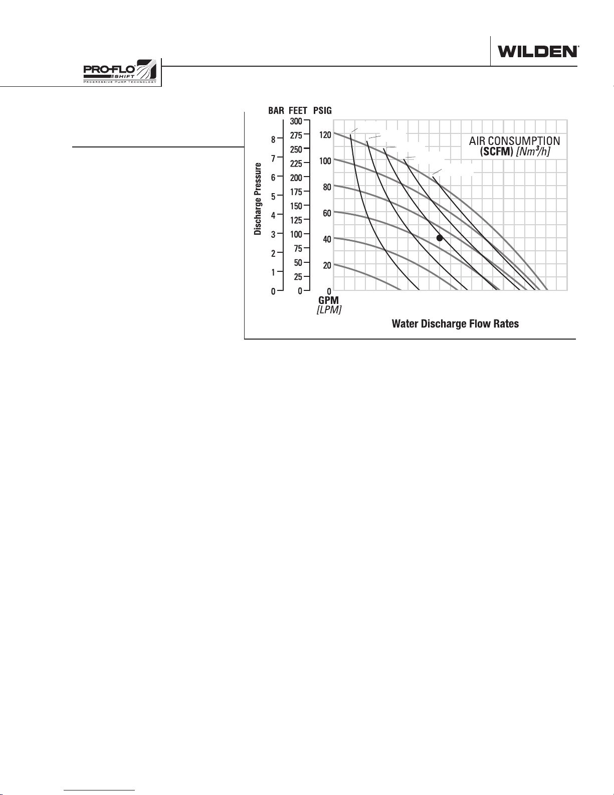
PS8 STALLION
EZ-INSTALL TPE-FITTED
Height .................................671 mm (26.4”)
Width ..................................612 mm (24.1”)
Depth ..................................459 mm (18.1”)
Ship Weight .......... Aluminum 36 kg (79 lb)
Ductile Iron 49 kg (109 lb)
Air Inlet ................................... 19 mm (3/4”)
Inlet ............................................ 51 mm (2”)
Outlet .........................................51 mm (2”)
Suction Lift ........................5.3 m Dry (17.5’)
9.0 m Wet (29.5’)
Disp. per Stroke ................. 2.0 L (0.52 gal)
Max. Flow Rate ............ 634 lpm (168 gpm)
Max. Size Solids ..................... 19 mm (3/4”)
1
Displacement per stroke was calculated at
4.8 bar (70 psig) air inlet pressure against a
2.1 bar (30 psig) head pressure.
Example: To pump 303 lpm (80 gpm)
against a discharge head of 2.1 bar
(30 psig) requires 4.1 bar (60 psig) and
3
71 Nm
/h (42 scfm) air consumption.
Caution: Do not exceed 8.6 bar (125 psig)
air supply pressure.
1
Flow rates indicated on chart were determined by pumping water.
For optimum life and performance, pumps should be specified so that daily operation
parameters will fall in the center of the pump's performance curve.
WILDEN PUMP & ENGINEERING, LLC 6 WIL-10830-E-02
20 40 60 80 100 120 140 160 180 200 220
PERFORMANCE
PS15 STALLION
EZ-INSTALL TPE-FITTED
Height .................................828 mm (32.6”)
Width .................................. 742 mm (29.2”)
Depth .................................. 498 mm (19.6”)
Ship Weight ........ Aluminum 63 kg (138 lb)
Air Inlet ................................... 19 mm (3/4”)
Inlet ............................................ 76 mm (3”)
Outlet ......................................... 76 mm (3”)
Suction Lift ....................... 4.7 m Dry (15.3’)
9.0 m Wet (29.5’)
Disp. per Stroke ................. 3.7 L (0.97 gal)
Max. Flow Rate ............ 764 lpm (202 gpm)
Max. Size Solids ........................25 mm (1”)
1
Displacement per stroke was calculated at
4.8 bar (70 psig) air inlet pressure against a
2.1 bar (30 psig) head pressure.
Example: To pump 379 lpm (100 gpm)
against a discharge head of 2.8 bar
(40 psig) requires 4.8 bar (70 psig) and
3
99 Nm
/h (58 scfm) air consumption.
Caution: Do not exceed 8.6 bar (125 psig)
air supply pressure.
1
20[34]
40[68]
60[102]
80[136]
100[170]
[76] [151] [227] [303] [379] [454] [530] [606] [681] [757] [833]
Flow rates indicated on chart were determined by pumping water.
For optimum life and performance, pumps should be specified so that daily operation
parameters will fall in the center of the pump's performance curve.
WIL-10830-E-02 7 WILDEN PUMP & ENGINEERING, LLC
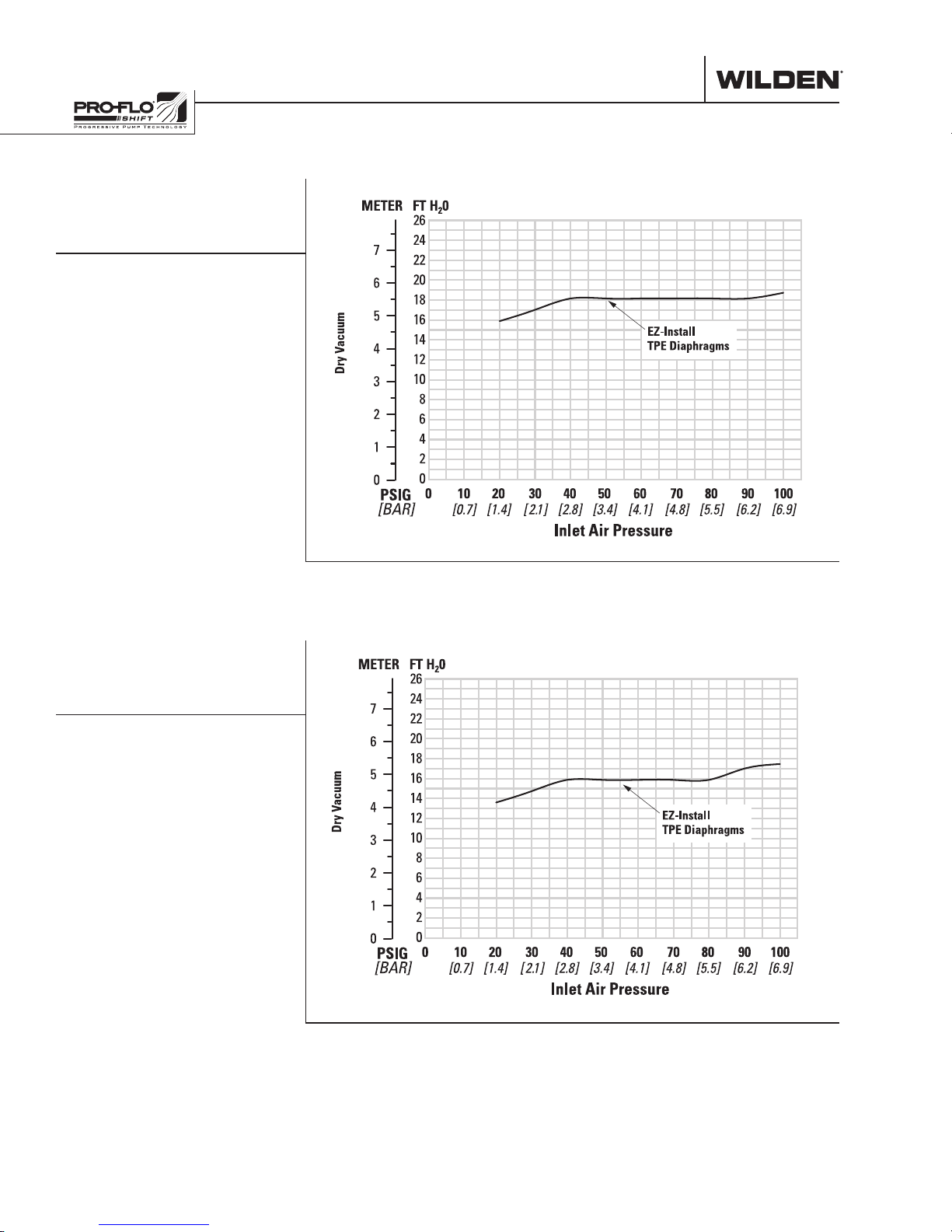
SUCTION-LIFT CURVES SUCTION-LIFT CURVES
PS4 Stallion
METAL SUCTION-
LIFT CAPABILITY
PS8 Stallion
METAL SUCTION-
LIFT CAPABILITY
Suction lift curves are calibrated for pumps operating
at 305 m (1,000') above sea level. This chart is meant
to be a guide only. There are many variables which
can affect your pump’s operating characteristics. The
EZ-Install
TPE Diaphragms
number of intake and discharge elbows, viscosity of
pumping fluid, elevation (atmospheric pressure) and
pipe friction loss all affect the amount of suction lift
your pump will attain.
WILDEN PUMP & ENGINEERING, LLC 8 WIL-10830-E-02
 Loading...