

Wilden P820, P830 Engineering, Operation & Maintenance
EOM
Engineering
Operation &
Maintenance
P820/P830
FIT Metal Pump
Where Innovation Flows
wildenpump.com
TABLE OF CONTENTS
SECTION 1 CAUTIONS—READ FIRST! ..............................................1
SECTION 2 WILDEN PUMP DESIGNATION SYSTEM .................................2
SECTION 3 HOW IT WORKS—PUMP & AIR DISTRIBUTION SYSTEM ................3
SECTION 4 DIMENSIONAL DRAWINGS .............................................4
SECTION 5 PERFORMANCE
P820/P830 Metal Rubber-Fitted ..............................................6
P820/P830 Metal EZ-Install TPE-Fitted .........................................6
P820/P830 Metal Reduced-Stroke PTFE-Fitted ..................................7
P820/P830 Metal Full-Stroke PTFE-Fitted ......................................7
Suction-Lift Curves ........................................................8
SECTION 6 SUGGESTED INSTALLATION, OPERATION & TROUBLESHOOTING .......10
SECTION 7 DISASSEMBLY / REASSEMBLY ........................................13
Air Valve / Center Section Disassembly ......................................16
Reassembly Hints & Tips ..................................................19
SECTION 8 EXPLODED VIEW & PARTS LISTING
P820/P830 Metal .........................................................20
SECTION 9 ELASTOMER OPTIONS .................................................22
Section 1
CAUTIONS—READ FIRST!
CAUTION : Do not apply compressed air to the
exhaust port — pump will not function.
CAUTION: Do not over-lubricate air supply —
excess lub rication will reduce pump p erformance .
Pump is pre-lubed.
TEMPERATURE LIMITS:
Acetal –29°C to 82°C –20°F to 180°F
Buna-N –12°C to 82°C 10°F to 180°F
Geolast
®
–40°C to 82°C –40°F to 180°F
Neoprene –18°C to 93°C 0°F to 200°F
Nordel
®
EPDM –51°C to 138°C –60°F to 280°F
Nylon –18°C to 93°C 0°F to 200°F
PFA –7°C to 107°C 45°F to 225°F
Polypropylene 0°C to 79°C 32°F to 175°F
Polyurethane –12°C to 66°C 10°F to 150°F
PVDF –12°C to 107°C 10°F to 225°F
Saniflex™ –29°C to 104°C –20°F to 220°F
SIPD PTFE with EPDM-backed
SIPD PTFE with Neoprene-backed
PTFE
Viton
1
4°C to 104°C 40°F to 220°F
®
FKM –40°C to 177°C –40°F to 350°F
4°C to 137°C 40°F to 280°F
4°C to 93°C 40°F to 200°F
Wil-Flex™ –40°C to 107°C –40°F to 225°F
1
4°C to 149°C (40°F to 300°F) - 13 mm (1/2") and 25 mm (1") models only.
CAUTION: Do not exceed 82°C (180°F) air inlet
®
temperature for Pro-Flo
models.
CAUTION: Pumps should be thoroughly flushed
before installing into process lines. FDA- and
USDA-approved pumps should be cleaned and /
or sanitized before being used.
CAUTION: Always wear safety glasses when
operating pump. If diaphragm rupture occurs,
material being pumped may be forced out air
exhaust.
CAUTION: Before any maintenance or repair is
attempted, the compressed air line to the pump
should be disconnected and all air pressure
allowed to bleed from pump. Disconnect all
intake, discharge and air lines. Drain the pump
by turning it upside down and allowing any fluid
to flow into a suitable container.
CAUTION: Blow out air line for 10 to 20 seconds
before attaching to pump to make sure all pipeline
debris is clear. Use an in-line air filter. A 5μ
(micron) air filter is recommended.
NOTE:
Not all materials are available for all models.
Refer to Section 2 for material options for your pump.
CAUTION: When choosing pump materials, be
sure to check the temperature limits for all wet-
ted components. Example: Viton® has a maxi-
mum limit of 177°C (350°F), but polypropylene
has a maximum limit of only 79°C (175°F).
CAUTION: Maximum temperature limits are
based upon mechanical stress only. Certain
chemicals will significantly reduce maximum
safe operating temperatures. Please consult the
Wilden Chemical Resistance Guide.
WARNING : Prevent static sparking — If static
sparking occurs, fire or explosion could result.
Pump, valves and containers must be grounded
to a proper grounding point when handling
flammable fluids and whenever discharge of
static electricity is a hazard.
CAUTION: Do not exceed 8.6 bar (125 psig) air
supply pressure.
CAUTION: The process fluid and cleaning fluids
must be chemically compatible with all wetted
pump components. Please consult the Wilden
Chemical Resistance Guide.
NOTE: When installing PTFE diaphragms, it is
important to tighten outer pistons simultaneously
(turning in opposite directions) to ensure tight fit.
(See torque specifications in Section 7.)
NOTE: Some PTFE-fitted pumps come standard
from the factory with expanded PTFE gaskets
installed in the diaphragm bead of the liquid
chamber. PTFE gaskets cannot be re-used.
NOTE: Before starting disassembly, mark a line
from each liquid chamber to its corresponding air
chamber. This line will assist in proper alignment
during reassembly.
CAUTION: Pro-Flo® pumps cannot be used
in submersible applications. Pro-Flo® SHIFT
pumps do have a single-point exhaust option
for submersible applications. Do not use
®
standard Pro-Flo
SHIFT models in submersible
applications.
CAUTION : Tighten all hardware prior to installation.
WIL-115 9 0 -E- 01 1 WILDEN PUMP & ENGINEERING, LLC
Section 2
WILDEN PUMP DESIGNATION SYSTEM
P820/P830 METAL
51 mm (2") Pump
Maximum Flow Rate:
609 lpm (161 gpm)
MATERIAL CODES
LEGEND
MODEL
XP 8 2 0 = PRO-FLO® THREADED
XP83 0 = PRO-FLO® FL ANGED
WETTED PARTS/OUTER PISTON
AA = ALUMINUM / ALUMINUM
SS = STAINLESS ST EEL /
STAINLESS STEEL
WW
AIR CHAMBERS
A = ALUMINUM
CENTER BLOCK
P = POLYPROP YLENE
AIR VALVE
P = POLYPROPYL ENE
PORTS
PORTS
= DUC TILE IRON /
DUCTILE IRON
P820 / XXX XX / XXX / XX / XXX / XXXX
MODEL
DIAPHRAGMS
VALVE BALLS
AIR VALVE
CENTER BLOCK
AIR CHAMBERS
WETTED PARTS & OUTER PISTON
DIAPHRAGMS
BNS = BUNA-N (Red Dot)
EPS = EPDM (Blue Dot)
FWS = SANITARY WIL-FLEXTM,
EZ-INSTALL [Santoprene®
(Two Black Dots)]
NES = NEOPRENE (Green Dot)
TEU = PTFE W/EPDM BACKUP
(White)
TNU = PTFE W/NEOPRENE
BACKUP (White)
TSS = FULL-STROKE PTFE W/
SANIFLEX™ BACK-UP
TSU = PTFE W/SANIFLEX™
BACKUP (White)
TWS = FULL-STROKE PTFE W/WIL-
FLEX™ BACKUP
VTS = VITON® (White Dot)
XBS = CONDUCTIVE BUNA-N
(Two Red Dots)
ZGS = GEOLAST®, EZ-INSTALL
(Black)
ZPS = POLYURETHANE, EZ-INSTALL
(Clear)
ZSS = SANIFLEX™, EZ-INSTALL
[Hytrel® (Cream)]
ZWS = WIL-FLEX™, EZ-INSTALL
[Santoprene® (Three Black
Dots)]
O-RINGS
VALVE SE ATS
VALVE BALLS
BN = BUNA-N (Red Dot)
FS = SANIFLEX™ [Hytrel® (Cream)]
FW = SANITARY WIL-FLEXTM
[Santoprene®
(Two Black Dots)]
EP = EPDM (Blue Dot)
NE = NEOPRENE (Green Dot)
PU = POLYURETHANE (Brown)
TF = PTFE (White)
VT = VITON® (Silver or White Dot)
WF = WIL-FLEX™ [Santoprene®
VALVE SEATS
A = ALUMINUM
BN = BUNA-N (Red Dot)
EP = EPDM (Blue Dot)
FS = SANIFLEX™ [Hytrel® (Cream)]
FW = SANITARY WIL-FLEXTM
[Santoprene®
(Two Black Dots)]
M = MILD STEEL
NE = NEOPRENE (Green Dot)
PU = POLYURETHANE (Brown)
S = STAINLESS STEEL
VT = VITON® (White Dot)
WF = WIL-FLEX™ [Santoprene®
SPECIALT Y
CODE
(if applicable)
(Three Black Dots)]
(Three Black Dots)]
SPECIALTY CODES
0014 BSPT
0100 Wil-Gard 110V
0102 Wil-Gard sensor wires ONLY
0103 Wil-Gard 220V
NOTE: Most elastomeric materials use colored dots for identification.
NOTE: Not all models are available with all material options.
Viton® is a registered trademark of DuPont Dow Elastomers.
WILDEN PUMP & ENGINEERING, LLC 2 WIL-115 9 0 -E- 01
0480 Pump Cycle Monitor (sensor & wires)
0483 Pump Cycle Monitor (module, sensor & wires)
0485 Pump Cycle Monitor (module, sensor & wires), DIN flange
0504 DIN flange
VALVE SEAT O-RINGS
TF = PTFE
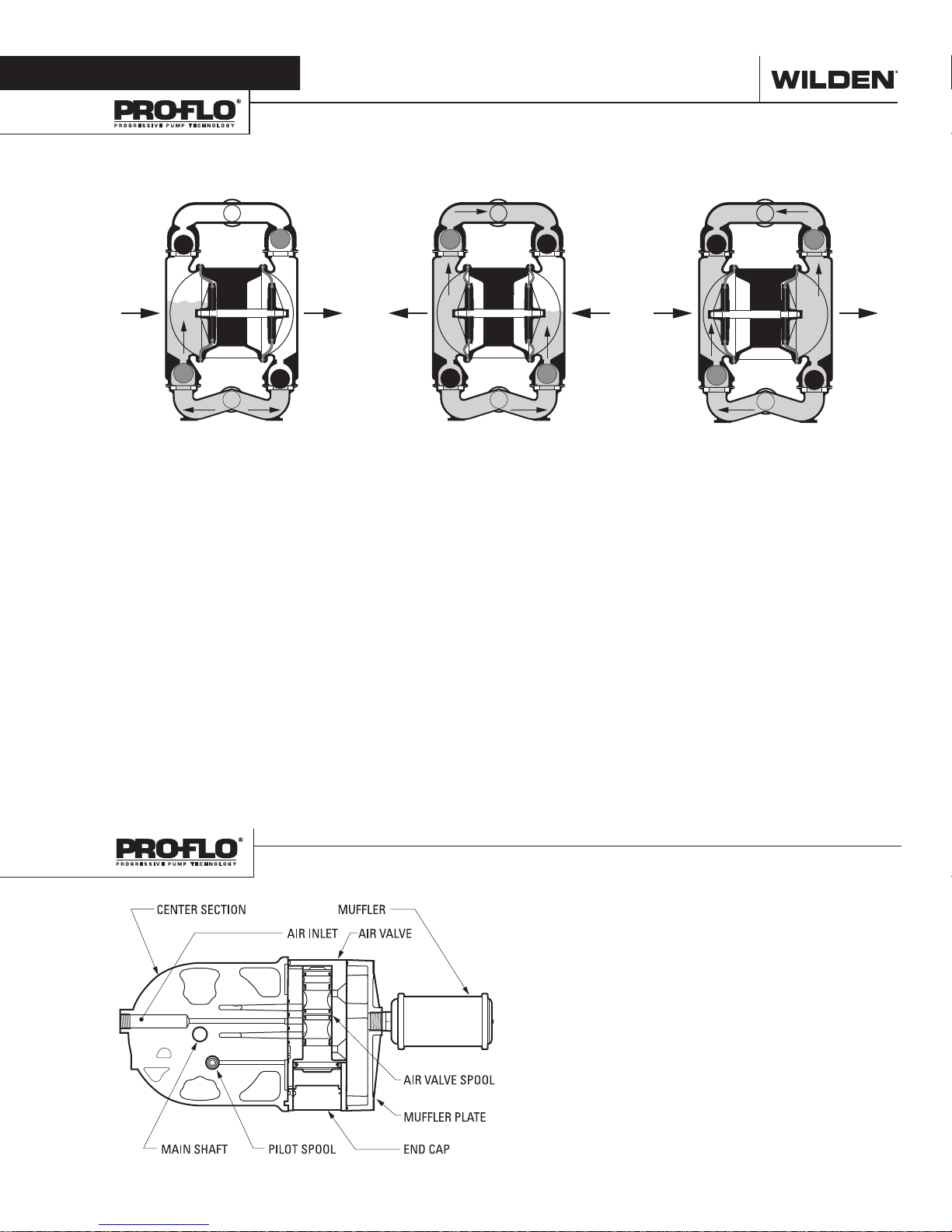
Section 3
HOW IT WORKS—PUMP
The Wilden diaphragm pump is an air-operated, positive displacement, self-priming pump. These drawings show flow pattern
through the pump upon its initial stroke. It is assumed the pump has no fluid in it prior to its initial stroke.
CLOSED
OUTLET
OPEN
B A
INLET
FIGUR E 1 The air valve dire cts pre ssurized
air to the back side of diaphragm A. The
compressed air is applied directly to the
liquid column separated by elastomeric
diaphragms. The diaphragm ac ts as
a separation membrane bet ween the
compressed air and liquid; a balanced
load removes mechanical stress from the
diaphragm. The compressed air moves
the diaphragm away from the center
of the pump. The opposite diaphragm
is pulled in by the shaft connected to
the pressurized diaphragm. Diaphragm
B is on its suction stroke; air behind
the diaphragm has been forced out to
atmosphere through the exhaust port of
the pump. The movement of diaphragm
B toward the center of the pump creates
a vacuum within chamber B. A tmosphe ric
pressure forces fluid into the inlet
manifold forcing the inlet valve ball off its
seat. Liquid is free to move past the inlet
valve ball and fill the liquid chamber (see
shaded area).
CLOSEDOPEN
OPEN
OUTLET
CLOSED
B A
CLOSED OPEN
FIGURE 2
phragm
, diaphragm A, reaches the limit
of its discharge stroke, the air valve
redirects pressurized air to the back side of
diaphragm B. The pressurized air forces
diaphragm B away from the center
while pulling diaphragm A to the center.
Diaphragm B is now on its discharge
stroke. Diaphragm B forces the inlet valve
ball onto its seat due to the hydraulic
forces developed in the liquid chamber
and manifold of the pump. These same
hydraulic forces lift the discharge valve
ball off its seat, while the opposite
discharge valve ball is forced onto its seat,
forcing fluid to flow through the pump
discharge. The movement of diaphragm A
toward the center of the pump creates a
vacuum within liquid chamber A. Atmospheric pressure forces fluid into the inlet
manifold of the pump. The inlet valve ball
is forced off its seat allowing the fluid
being pumped to fill the liquid chamber.
INLET
When the pressurized dia-
CLOSED OPEN
OUTLET
B A
OPEN
FIGURE 3 At completion of the stroke,
the air valve again redirects air to the
back side of diaphragm A, which starts
diaphragm B on its exhaust stroke. As
the pump reaches its original star ting
point, each diaphragm has gone through
one exhaust and one discharge stroke.
This constitutes one complete pumping
cycle. The pump may take several cycles
to completely prime depending on the
conditions of the application.
INLET
CLOSED
HOW IT WORKS—AIR DISTRIBUTION SYSTEM
WIL-115 9 0 -E- 01 3 WILDEN PUMP & ENGINEERING, LLC
The Pro-Flo® patented air distribution system incorporates
two moving par ts : the air valve spool and the pilot spool. The
heart of the system is the air valve spool and air valve. This
valve design incorporates an unbalanced spool. The smaller
end of the spool is pressurized continuously, while the large
end is alternately pressurized then exhausted to move the
spool. The spool directs pressurized air to one air chamber
while exhausting the other. The air causes the main shaft/
diaphragm assembly to shif t to one side — discharging liquid
on that side and pulling liquid in on the other side. When the
shaft reaches the end of its stroke, the inner piston actuates
the pilot spool, which pressurizes and exhausts the large end
of the air valve spool. The repositioning of the air valve spool
routes the air to the other air chamber.
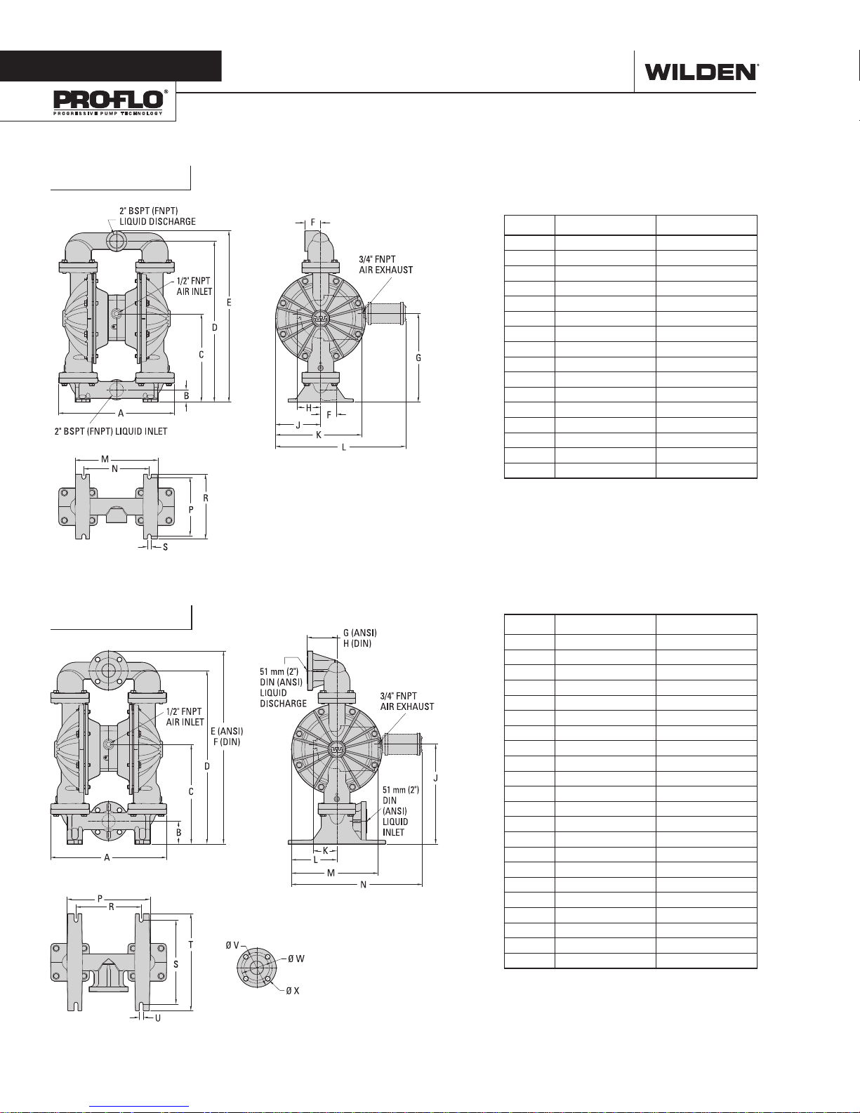
Section 4
P820 Metal
DIMENSIONAL DRAWINGS
DIMENSIONS
ITEM METRIC (mm) STANDARD (Inch)
A 453 17.9
B 48 1.9
C 346 13.6
D 630 24.8
E 670 26.4
F 62 2.4
G 347 13.7
H 93 3.7
J 177 7.0
K 338 13.3
L 510 20.1
M 324 12.8
N 257 10.1
P 229 9.0
R 254 10.0
S 14 0.6
LW0369 REV. A
P830 Metal
DIMENSIONS
ITEM METRIC (mm) STANDARD (Inch)
A 452 17.8
B 89 3.5
C 387 15.3
D 675 26.6
E 752 29.6
F 758 29.8
G 116 4.6
H 117 4.6
J 389 15.3
K 93 3.7
L 177 7.0
M 338 13.3
N 510 20.1
P 324 12.8
R 254 10.0
S 326 12.8
T 378 14.9
U 16 0.6
DIN (mm) ANSI (Inch)
V 165 DIA. 6.0 DIA.
W 125 DIA. 4.8 DIA.
X 18 DIA. 0.8 DIA.
LW0370 REV. A
WILDEN PUMP & ENGINEERING, LLC 4 WIL-115 9 0 -E- 01
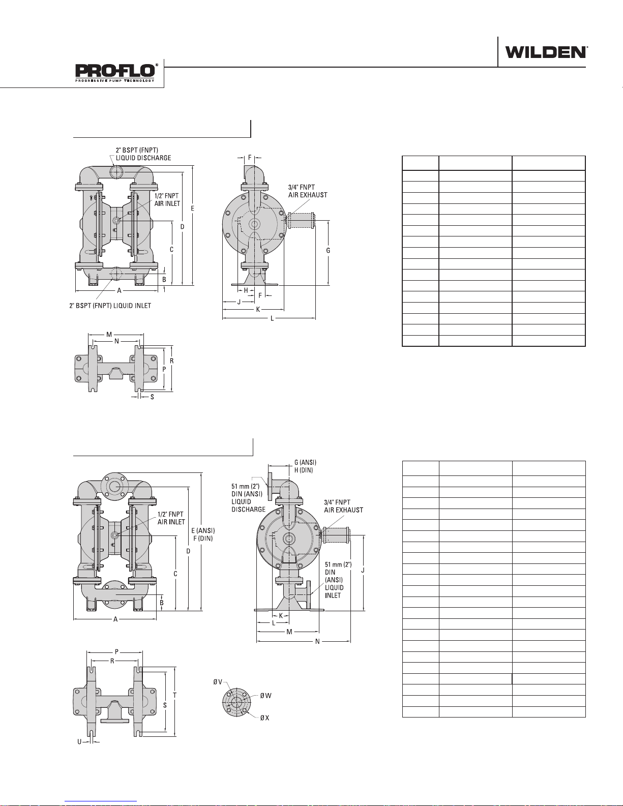
DIMENSIONAL DRAWINGS
P820 Stainless Steel
DIMENSIONS
ITEM METRIC (mm) STANDARD (Inch)
A 452 17.8
B 64 2.5
C 354 14.0
D 620 24.4
E 658 25.9
F 58 2.3
G 356 14.0
H 93 3.7
J 178 7.0
K 338 13.3
L 510 20.1
M 305 12.0
N 254 10.0
P 229 9.0
R 254 10.0
S 15 0.6
LW0371 REV. A
P830 Stainless Steel
DIMENSIONS
ITEM METRIC (mm) STANDARD (Inch)
A 452 17.8
B 89 3.5
C 412 16.2
D 678 26.7
E 754 29.7
F 760 29.9
G 116 4.6
H 115 4.5
J 413 16.3
K 93 3.7
L 177 7.0
M 338 13.3
N 510 20.1
P 304 12.0
R 254 10.0
S 325 12.8
T 379 14.9
U 14 0.6
DIN (mm) ANSI (Inch)
V 165 DIA. 6.0 DIA.
W 125 DIA. 4.8 DIA.
X 18 DIA. 0.8 DIA.
LW0372 REV. A
WIL-115 9 0 -E- 01 5 WILDEN PUMP & ENGINEERING, LLC
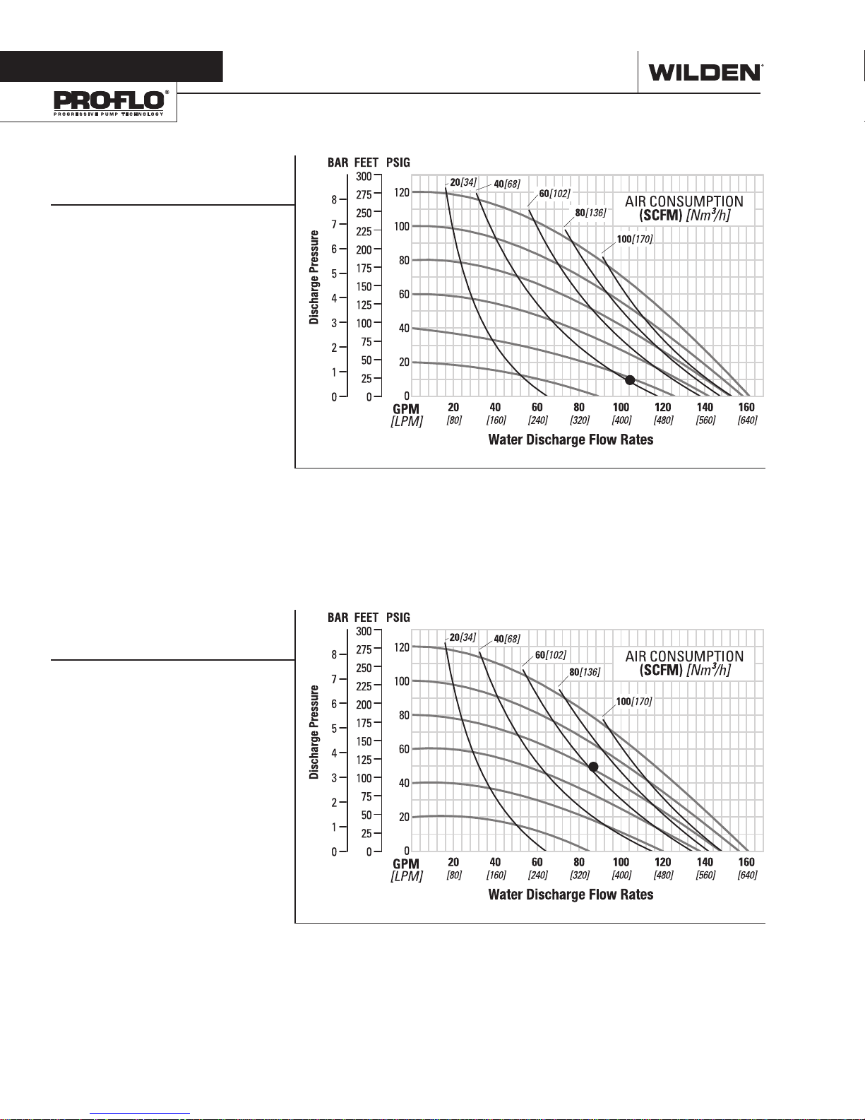
Section 5
PERFORMANCE
P820/P830 METAL
RUBBER-FITTED
Ship Weight ... 820 Threaded AL 47 kg (104 lb)
820 Threaded SS 73 kg (161 lb)
820 Threaded Iron 71 kg (156 lb)
830 Flanged AL 54 kg (118 lb)
830 Flanged SS 81 kg (178 lb)
830 Flanged Iron 82 Kg (181 lb)
Air Inlet ........................................19 mm (3/4”)
Inlet .................................................51 mm (2”)
Outlet ..............................................51 mm (2”)
Suction Lift .............................7.4 m Dry (24.3’)
9.0 m Wet (29.5’)
Disp. per Stroke1 ...................... 2.8 L (0.74 gal)
Max. Flow Rate ................. 609 lpm (161 gpm)
Max. Size Solids .........................6.4 mm (1/4”)
1
Displacement per stroke was calculated at
4.8 bar (70 psig) air inlet pressure against
2 bar (30 psig) head pressure.
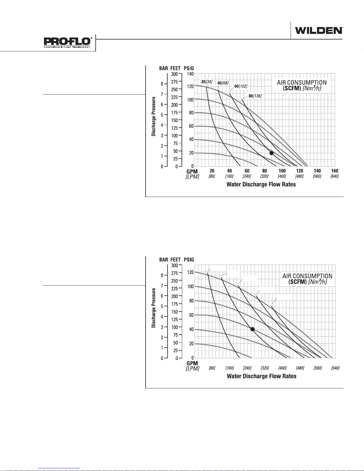
Example: To pump 394 lpm (104 gpm) against
a discharge head of 0.69 bar (10 psig) requires
2.8 bar (40 psig) and 63 Nm3/h (40 scfm) air
consumption.
Caution: Do not exceed 8.6 bar (125 psig) air
supply pressure.
Flow rates indicated on chart were determined by pumping water.
For optimum life and performance, pumps should be specified so that daily operation
parameters will fall in the center of the pump's performance curve.
P820/P830 METAL
EZ-INSTALL TPE-FITTED
Ship Weight ... 820 Threaded AL 47 kg (104 lb)
820 Threaded SS 73 kg (161 lb)
820 Threaded Iron 71 kg (156 lb)
830 Flanged AL 54 kg (118 lb)
830 Flanged SS 81 kg (178 lb)
830 Flanged Iron 82 Kg (181 lb)
Air Inlet ........................................19 mm (3/4”)
Inlet .................................................51 mm (2”)
Outlet ..............................................51 mm (2”)
Suction Lift ............................ 6.7 m Dry (21.9’)
9.0 m Wet (29.5’)
Disp. per Stroke
Max. Flow Rate ................. 605 lpm (160 gpm)
Max. Size Solids .........................6.4 mm (1/4”)
1
Displacement per stroke was calculated at
4.8 bar (70 psig) air inlet pressure against
2 bar (30 psig) head pressure.
Example: To pump 326 lpm (86 gpm) against
a discharge head of 3.4 bar (50 psig) requires
5.5 bar (80 psig) and 98 Nm3/h (62 scfm) air
consumption.
Caution: Do not exceed 8.6 bar (125 psig) air
supply pressure.
1
...................... 2.5 L (0.67 gal)
Flow rates indicated on chart were determined by pumping water.
For optimum life and performance, pumps should be specified so that daily operation
parameters will fall in the center of the pump's performance curve.
WILDEN PUMP & ENGINEERING, LLC 6 WIL-115 9 0 -E- 01
PERFORMANCE
P820/P830 METAL
REDUCED-STROKE
PTFE-FITTED
Ship Weight ... 820 Threaded AL 47 kg (104 lb)
820 Threaded SS 73 kg (161 lb)
820 Threaded Iron 71 kg (156 lb)
830 Flanged AL 54 kg (118 lb)
830 Flanged SS 81 kg (178 lb)
830 Flanged Iron 82 Kg (181 lb)
Air Inlet ........................................19 mm (3/4”)
Inlet .................................................51 mm (2”)
Outlet ..............................................51 mm (2”)
Suction Lift ............................ 4.6 m Dry (15.1’)
9.0 m Wet (29.5’)
Disp. per Stroke
Max. Flow Rate ................. 492 lpm (130 gpm)
Max. Size Solids .........................6.4 mm (1/4”)
1
Displacement per stroke was calculated at
4.8 bar (70 psig) air inlet pressure against
2 bar (30 psig) head pressure.
Example: To pump 326 lpm (86 gpm) against
a discharge head of 1.4 bar (20 psig) requires
4.1 bar (60 psig) and 95 Nm3/h (60 scfm) air
consumption.
Caution: Do not exceed 8.6 bar (125 psig) air
supply pressure.
1
.......................1.7 L (0.46 gal)
Flow rates indicated on chart were determined by pumping water.
For optimum life and performance, pumps should be specified so that daily operation
parameters will fall in the center of the pump's performance curve.
P820/P830 METAL
FULL-STROKE
PTFE-FITTED
Ship Weight ... 820 Threaded AL 47 kg (104 lb)
820 Threaded SS 73 kg (161 lb)
820 Threaded Iron 71 kg (156 lb)
830 Flanged AL 54 kg (118 lb)
830 Flanged SS 81 kg (178 lb)
830 Flanged Iron 82 Kg (181 lb)
Air Inlet ........................................19 mm (3/4”)
Inlet .................................................51 mm (2”)
Outlet ..............................................51 mm (2”)
Suction Lift ............................6.9 m Dry (22.6’)
9.0 m Wet (29.5’)
Disp. per Stroke1 ...................... 2.5 L (0.65 gal)
Max. Flow Rate ................. 590 lpm (156 gpm)
Max. Size Solids .........................6.4 mm (1/4”)
1
Displacement per stroke was calculated at
4.8 bar (70 psig) air inlet pressure against
2 bar (30 psig) head pressure.
Example: To pump 250 lpm (66 gpm) against
a discharge head of 2.8 bar (40 psig) requires
4.1 bar (60 psig) and 65 Nm3/h (41 scfm) air
consumption.
Caution: Do not exceed 8.6 bar (125 psig) air
supply pressure.
20[34]
40[68]
60[102]
80[136]
100[170]
20 40 60 80 100 120 140 160
Flow rates indicated on chart were determined by pumping water.
For optimum life and performance, pumps should be specified so that daily operation
parameters will fall in the center of the pump's performance curve.
WIL-115 9 0 -E- 01 7 WILDEN PUMP & ENGINEERING, LLC
 Loading...