

Page 1
P800/PX800
Advanced™ Series PLASTIC Pumps
Advance your process
Engineering
Operation &
Maintenance
TO REPL ACE WIL-11250- E- 02
WIL-11250-E-03
Page 2

TABLE OF CONTENTS
SECTION 1 CAUTIONS—READ FIRST! . . . . . . . . . . . . . . . . . . . . . . . . . . . . . . . . . . . . . . . . . . . . . .1
SECTION 2 WILDEN PUMP DESIGNATION SYSTEM . . . . . . . . . . . . . . . . . . . . . . . . . . . . . . . . .2
SECTION 3 HOW IT WORKS—PUMP & AIR DISTRIBUTION SYSTEM . . . . . . . . . . . . . . . . 3
SECTION 4 DIMENSIONAL DRAWINGS . . . . . . . . . . . . . . . . . . . . . . . . . . . . . . . . . . . . . . . . . . . . .4
SECTION 5 PERFORMANCE
A. P800 Performance Curves
Rubber-Fitted . . . . . . . . . . . . . . . . . . . . . . . . . . . . . . . . . . . . . . . . . . . . . . . . . . . . . . . .6
TPE-Fitted . . . . . . . . . . . . . . . . . . . . . . . . . . . . . . . . . . . . . . . . . . . . . . . . . . . . . . . . . . .6
Reduced Stroke PTFE-Fitted . . . . . . . . . . . . . . . . . . . . . . . . . . . . . . . . . . . . . . . . . . . .7
Full Stroke-Fitted . . . . . . . . . . . . . . . . . . . . . . . . . . . . . . . . . . . . . . . . . . . . . . . . . . . . .7
Ultra-Flex™-Fitted . . . . . . . . . . . . . . . . . . . . . . . . . . . . . . . . . . . . . . . . . . . . . . . . . . . .8
Suction Lift Curve . . . . . . . . . . . . . . . . . . . . . . . . . . . . . . . . . . . . . . . . . . . . . . . . . . . .9
B. PX800 Performance Curves
Operating Principal . . . . . . . . . . . . . . . . . . . . . . . . . . . . . . . . . . . . . . . . . . . . . . . . . . . .12
How to Use this EMS Curve . . . . . . . . . . . . . . . . . . . . . . . . . . . . . . . . . . . . . . . . . . . . .13
Performance Curves
Rubber-Fitted . . . . . . . . . . . . . . . . . . . . . . . . . . . . . . . . . . . . . . . . . . . . . . . . . . . .16
TPE-Fitted . . . . . . . . . . . . . . . . . . . . . . . . . . . . . . . . . . . . . . . . . . . . . . . . . . . . . . .17
Reduced Stroke PTFE-Fitted . . . . . . . . . . . . . . . . . . . . . . . . . . . . . . . . . . . . . . . .18
Full Stroke-Fitted . . . . . . . . . . . . . . . . . . . . . . . . . . . . . . . . . . . . . . . . . . . . . . . . . .19
Ultra-Flex™-Fitted . . . . . . . . . . . . . . . . . . . . . . . . . . . . . . . . . . . . . . . . . . . . . . . . 20
Suction Lift Curve . . . . . . . . . . . . . . . . . . . . . . . . . . . . . . . . . . . . . . . . . . . . . . . . . . .21
SECTION 6 SUGGESTED INSTALLATION, OPERATION & TROUBLESHOOTING . . . . . . . 23
SECTION 7 DISASSEMBLY/REASSEMBLY
Pump Disassembly . . . . . . . . . . . . . . . . . . . . . . . . . . . . . . . . . . . . . . . . . . . . . . . . . . . . . . .25
Pro-Flo® Air Valve / Center Section Disassembly . . . . . . . . . . . . . . . . . . . . . . . . . . . . . . . 29
TM
Pro-Flo X
Reassembly Hints & Tips . . . . . . . . . . . . . . . . . . . . . . . . . . . . . . . . . . . . . . . . . . . . . . . . . . 34
Air Valve / Center Section Disassembly . . . . . . . . . . . . . . . . . . . . . . . . . . . . 32
SECTION 8 EXPLODED VIEW & PARTS LISTING
P800 PLASTIC
P800 Full Stroke-Fitted . . . . . . . . . . . . . . . . . . . . . . . . . . . . . . . . . . . . . . . . . . . . . . . . .36
P800 Reduced Stroke-Fitted . . . . . . . . . . . . . . . . . . . . . . . . . . . . . . . . . . . . . . . . . . . . .38
P800 PLASTIC
PX800 Full Stroke-Fitted . . . . . . . . . . . . . . . . . . . . . . . . . . . . . . . . . . . . . . . . . . . . . . . .40
PX800 Reduced Stroke-Fitted . . . . . . . . . . . . . . . . . . . . . . . . . . . . . . . . . . . . . . . . . . . .42
SECTION 9 ELASTOMER OPTIONS . . . . . . . . . . . . . . . . . . . . . . . . . . . . . . . . . . . . . . . . . . . . . . . . .44
Page 3
Section 1
CAUTIONS—READ FIRST!
CAUTION: Do not apply compressed air to the
exhaust port — pump will not function.
CAUTION: Do not over-lubricate air supply —
excess lubrication will reduce pump performance.
Pump is pre-lubed.
TEMPERATURE LIMITS:
Neoprene –17.7°C to 93.3°C 0°F to 200°F
Buna-N –12.2°C to 82.2°C 10°F to 180°F
EPDM –51.1°C to 137.8°C –60°F to 280°F
Viton
Sanifl ex™ –28.9°C to 104.4°C –20°F to 220°F
Polytetrafl uoroethylene (PTFE)
4.4°C to 104.4°C 40°F to 220°F
Polyurethane –12.2°C to 65.6°C 10°F to 150°F
Tetra-Flex™ PTFE w/Neoprene Backed
4.4°C to 107.2°C 40°F to 225°F
Tetra-Flex™ PTFE w/EPDM Backed
-10°C to 137°C 14°F to 280°F
Wil-Flex™ -40°C to 107.2°C (-40°F to 225°F)
®
–40°C to 176.7°C –40°F to 350°F
NOTE: Not all materials are available for all
models. Refer to Section 2 for material options
for your pump.
CAUTION: When choosing pump materials, be
sure to check the temperature limits for all wetted
components. Example: Viton® has a maximum
limit of 176.7°C (350°F) but polypropylene has a
maximum limit of only 79°C (175°F).
CAUTION: Maximum temperature limits are
based upon mechanical stress only. Certain
chemicals will signifi cantly reduce maximum
safe operating temperatures. Consult Chemical
Resistance Guide (E4) for chemical compatibility
and temperature limits.
WARNING: Prevention of static sparking — If
static sparking occurs, fi re or explosion could
result.
CAUTION: Always wear safety glasses when
operating pump. If diaphragm rupture occurs,
material being pumped may be forced out air
exhaust.
CAUTION: Before any maintenance or repair is
attempted, the compressed air line to the pump
should be disconnected and all air pressure
allowed to bleed from pump. Disconnect all
intake, discharge and air lines. Drain the pump
by turning it upside down and allowing any fl uid
to fl ow into a suitable container.
CAUTION: Blow out air line for 10 to 20 seconds
before attaching to pump to make sure all pipeline
debris is clear. Use an in-line air fi lter. A 5µ (micron)
air fi lter is recommended.
CAUTION: If the pipe plug in the inlet or discharge
manifold on the 51 mm (2") Advanced™ plastic
center-ported model is removed, a triple density
(red) PTFE pipe tape is recommended to ensure
adequate sealing.
NOTE: When installing PTFE diaphragms, it is
important to tighten outer pistons simultaneously
(t ur ning in oppo site direc tions) to ensure tight fi t.
(See torque specifi cations in Section 7.)
NOTE: Before starting disassembly, mark a line
from each liquid chamber to its corresponding air
chamber. This line will assist in proper alignment
during reassembly.
CAUTION: Pro-Flo® pumps cannot be used in
submersible applications. Pro-Flo X™ is available
in both submersible and non-submersible
options. Do not use non-submersible Pro-Flo X™
models in submersible applications.
CAUTION: Tighten all hardware prior to installation.
CAUTION: Do not exceed 8.6 bar (125 psig) air
supply pressure.
CAUTION: The process fl uid and cleaning fl uids
must be chemically compatible with all wetted
pump components. Consult Chemical Resistance
Guide (E4).
CAUTION: Do not exceed 82°C (180°F) air inlet
temperature for Pro-Flo X™ models.
WIL-11250-E-03 1 WILDEN PUMP & ENGINEERING, LLC
Page 4
Section 2
WILDEN PUMP DESIGNATION SYSTEM
P800/PX800 PLASTIC
51 mm (2") Pump
Maximum Flow Rate:
693 lpm (183 gpm)
LEGEND
MATERIAL CODES
MODEL
P800 = PRO-FLO
PX8 00 = PRO-F LO X™
WETTED PARTS
KK = PVDF / PVDF
PK = POLYPROPYLENE / PVDF
AIR CHAMBERS
P = POLYPROP YLENE
CENTER BLOCK
P = POLYPROP YLENE
AIR VALVE
P = POLYPROP YLENE
L = ACETAL (P800 only)
®
PX800 / XXXXX / XXX / XX/ XXX / XXXX
MODEL
VALVE BALLS
DIAPHRAGMS
AIR VALVE
CENTER BLOCK
AIR CHAMBERS
WETTED PARTS & OUTER PISTON
DIAPHRAGMS
BNS = BUNA-N (Red Dot)
BNU = BUNA-N, ULTRA-FLEX™
EPS = EPDM (Blue Dot)
EPU = EPDM, ULTRA-FLEX™
FSS = SANIFLEX™
[Hytrel® (Cream)]
NES = NEOPRENE (Green Dot)
NEU = NEOPRENE, ULTRA-FLEX™
PUS = POLYURETHANE (Clear)
TEU = PTFE W/EPDM
BACK-UP (White)
TNU = PTFE W/NEOPRENE
BACK-UP (White)
TSU = PTFE W/SANIFLEX™
BACK-UP (White)
VTS = VITON® (White Dot)
VTU = VITON®, ULTRA-FLEX™
WFS = WIL-FLEX™ [Santoprene®
(Orange Dot)]
TSS = FULL STROKE PTFE
W/SANIFLEX™ BACK-UP
TWS = FULL STROKE PTFE
W/WIL-FLEX™ BACK-UP
O-RINGS
VALVE SEAT
VALVE BALL
BN = BUNA-N (Red Dot)
EP = EPDM (Blue Dot)
FS = SANIFLEX™
[Hytrel® (Cream)]
NE = NEOPRENE (Green Dot)
PU = POLYURETHANE (Clear)
TF = PT FE (White)
VT = VITON® (White Dot)
WF = WIL-FLEX™ [Santoprene®
(Orange Dot)]
VALVE SEAT
K = PVDF
P = POLYPROPY LENE
VALVE SEAT & FLANGE O-RING
BN = BUNA-N
TV = PT FE ENCAP. VI TON
WF = WIL-FL E X ™ ( San top rene )
SPECIALTY
CODE
(if applicable)
®
SPECIALTY CODES
0100 Wil-Gard 110V
0102 Wil-Gard sensor wires ONLY
0103 Wil-Gard 220V
0206 PFA coated hardware,
Wil-Gard II™ sensor wires ONLY
0480 Pump Cycle Monitor (sensor & wires)
0483 Pump Cycle Monitor (module, sensor & wires)
0485 Pump Cycle Monitor (module, sensor & wires),
DIN flange
NOTE: MOST EL ASTOMERIC M ATERIALS USE COLORED DOTS FOR IDEN TIF ICATION.
NOTE: Not all models are available with all material options.
®
Viton
is a registered trademark of DuPont Dow Elastomers.
0502 PFA Coated
0504 DIN Flange
0506 DIN Flange, PFA Coated
0513 SS outer pistons
0604 DIN flange Wil-Gard II™
0608 PFA coated hardware, Wil-Gard II™ 220V
0690 Center-Ported ANSI/DIN Combo
0691 Center-ported, ANSI/DIN combo flange, PFA
coated fasteners
WILDEN PUMP & ENGINEERING, LLC 2 WIL-11250-E-03
0733 Center-ported, Reversed ANSI/DIN combo
flange (inlet facing air inlet/discharge facing
exhaust)
0734 Center-ported, Reversed ANSI/DIN combo
flange (inlet facing air inlet/discharge facing
exhaust), PFA coated fasteners
Page 5
Section 3
HOW IT WORKS—PUMP
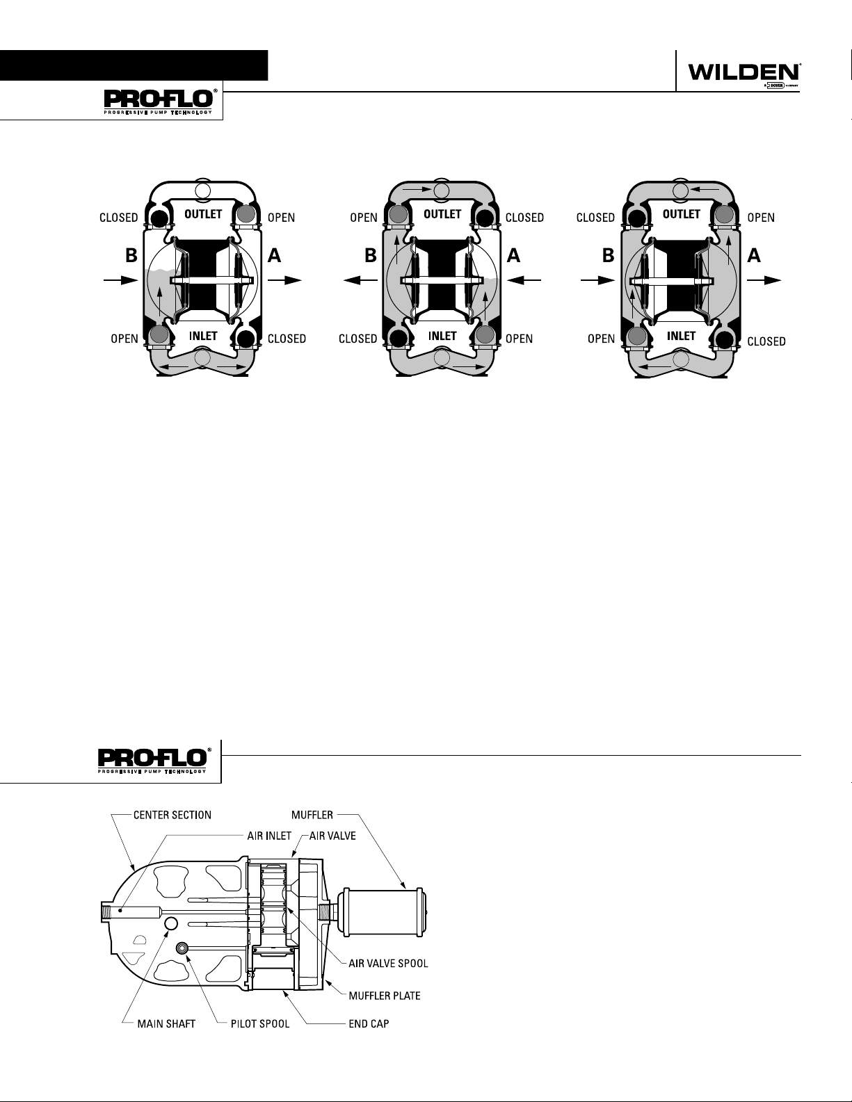
The Wilden diaphragm pump is an air-operated, positive displacement, self-priming pump. These drawings show fl ow pattern
through the pump upon its initial stroke. It is assumed the pump has no fl uid in it prior to its initial stroke.
FIGURE 1 The air valve dir ects pre ssurized
air to the back side of diaphragm A. The
compressed air is applied directly to the
liquid column separated by elastomeric
diaphragms. The diaphragm acts as
a separation membrane between the
compressed air and liquid, balancing the
load and removing mechanical stress
from the diaphragm. The compressed
air moves the diaphragm away from
the center of the pump. The opposite
diaphragm is pulled in by the shaf t
connected to the pressurized diaphragm.
Diaphragm B is on its suction stroke; air
behind the diaphragm has been forced
out to atmosphere through the exhaust
port of the pump. The movement of
diaphragm B toward the center of the
pump creates a vacuum within chamber B.
Atmospheric pressure forces fl uid into
the inlet manifold forcing the inlet valve
ball off its seat. Liquid is free to move
past the inlet valve ball and fi ll the liquid
chamber (see shaded area).
HOW IT WORKS—AIR DISTRIBUTION SYSTEM
FIGURE 2 When the pressurized diaphragm,
diaphra gm A, re aches t he limit of it s disc harge
stroke, the air valve redirects pressurized
air to the back side of diaphragm B. The
pressurized air forces diaphragm B away
from the center while pulling diaphragm A
to the center. Diaphragm B is now on its
discharge stroke. Diaphragm B forces the
inlet valve ball onto its seat due to the
hydraulic forces developed in the liquid
chamber and manifold of the pump. These
same hydraulic forces lift the discharge
valve ball off its seat, while the opposite
discharge valve ball is forced onto its seat,
forcing fl uid to fl ow through the pump
discharge. The movement of diaphragm A
toward the center of the pump creates a
vacuum within liquid chamber A. Atmospheric pressure forces fl uid into the inlet
manifold of the pump. The inlet valve ball
is forced off its seat allowing the fl uid being
pumped to fi ll the liquid chamber.
FIGURE 3 At completion of the stroke,
the air valve again redirects air to the
back side of diaphragm A, which star ts
diaphragm B on its exhaust stroke. As
the pump reaches its original starting
point, each diaphragm has gone through
one exhaust and one discharge stroke.
This constitutes one complete pumping
cycle. The pump may take several cycles
to completely prime depending on the
conditions of the application.
The Pro -Flo
moving parts : the air valve spool and the pilot spool. The heart of
the system is the air valve spool and air valve. This valve design
incorporates an unbalanced spool. The smaller end of the spool
is pressurized continuously, while the large end is alternately
pressurized then exhausted to move the spool. The spool directs
pressurized air to one air chamber while exhausting the other.
The air causes the main shaft/diaphragm assembly to shift to
one side — discharging liquid on that side and pulling liquid in
on the other side. When the shaft reaches the end of its stroke,
the inner piston actuates the pilot spool, which pressurizes and
exhausts the large end of the air valve spool. The repositioning
of the air valve spool routes the air to the other air chamber.
WIL-11250-E-03 3 WILDEN PUMP & ENGINEERING, LLC
®
patented air distribution system incorporates two
Page 6
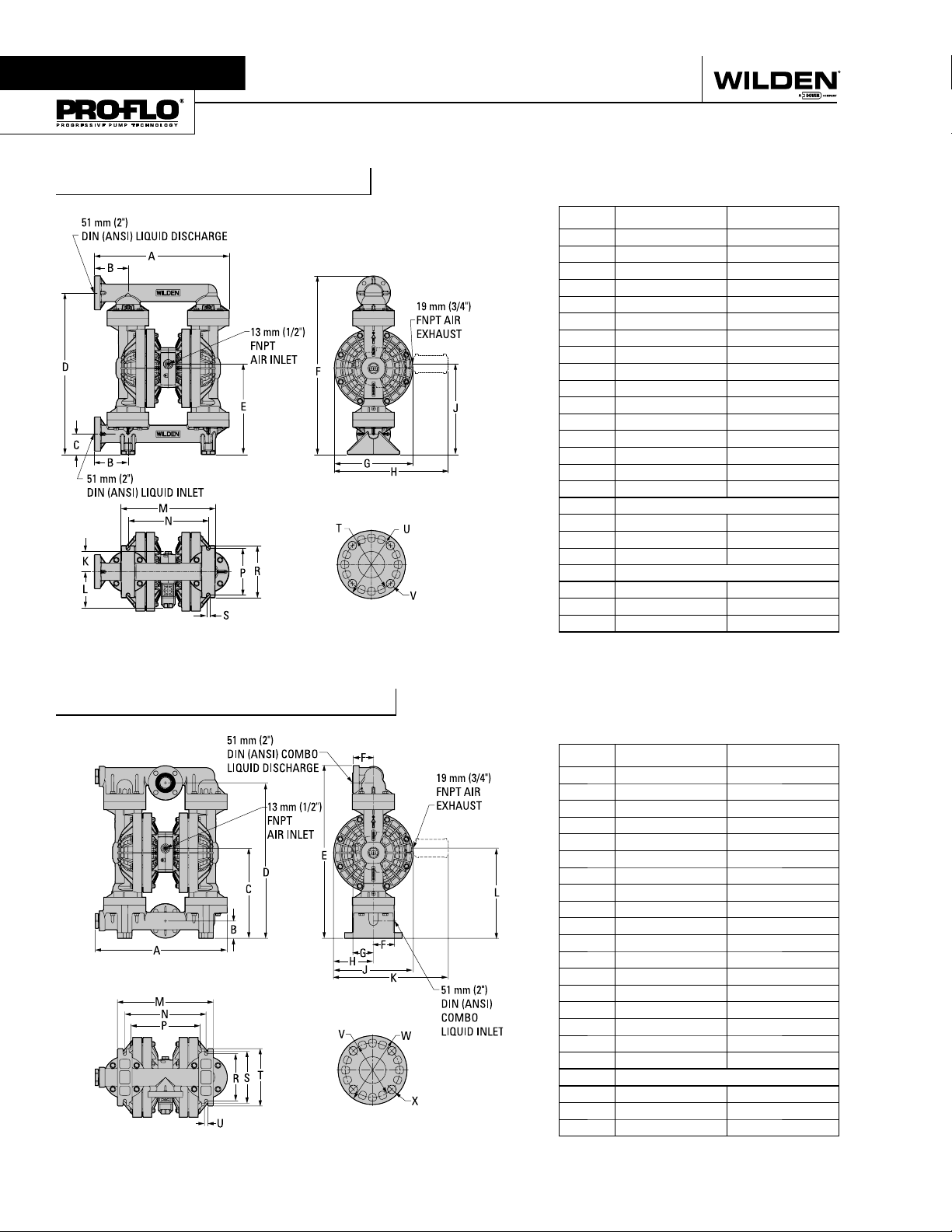
Section 4
DIMENSIONAL DRAWINGS
P800 Plastic Side-Ported
DIMENSIONS
ITEM METRIC (mm) STANDARD (inch)
A 605 23.8
B 150 5.9
C 91 3.6
D 729 28.7
E 406 16.0
F 805 31.7
G 353 13.9
H 508 20.0
J 406 16.0
K 84 3.3
L 122 4.8
M 424 16.7
N 361 14.2
P 208 8.2
R 234 9.2
S 15 0.6
DIN FLANGE
T 125 DIA. 4.9 DIA.
U 165 DIA. 6.5 DIA.
V 18 DIA. 0.7 DIA.
ANSI FLANGE
T 122 DIA. 4.8 DIA.
U 152 DIA. 6.0 DIA.
V 20 DIA. 0.8 DIA.
P800 Plastic Center-Ported
DIMENSIONS
ITEM METRIC (mm) STANDARD (inch)
A 584 23.0
B 76 3.0
C 396 15.6
D 688 27.1
E 765 30.1
F 89 3.5
G 91 3.6
H 175 6.9
J 353 13.9
K 508 20.0
L 399 15.7
M 424 16.7
N 361 14.2
P 307 12.1
R 208 8.2
S 229 9.0
T 254 10.0
U 15 0.6
DIN / ANSI COMBO
V
W
X
152 DIA. 6.0 DIA.
122 DIA. 4.8 DIA.
20 DIA. 0.8 DIA.
WILDEN PUMP & ENGINEERING, LLC 4 WIL-11250-E-03
Page 7
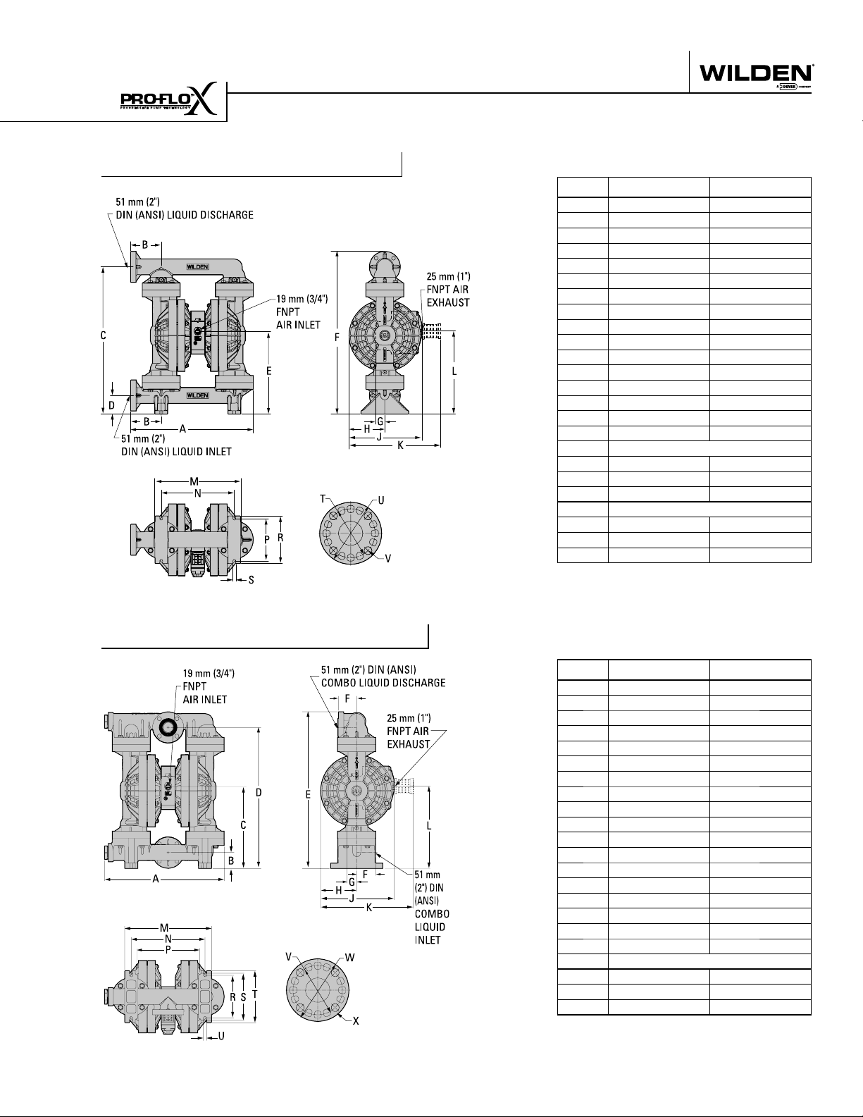
DIMENSIONAL DRAWING
PX800 Plastic Side-Ported
DIMENSIONS
ITEM METRIC (mm) STANDARD (inch)
A 605 23.8
B 150 5.9
C 729 28.7
D 91 3.6
E 406 16.0
F 805 31.7
G 48 1.9
H 178 7.0
J 356 14.0
K 452 17.8
L 414 16.3
M 424 16.7
N 361 14.2
P 208 8.2
R 234 9.2
S 15 0.6
DIN FLANGE
T 125 DIA. 4.9 DIA.
U 165 DIA. 6.5 DIA.
V 18 DIA. .7 DIA.
ANSI FLANGE
T 122 DIA. 4.8 DIA.
U 154 DIA. 6.0 DIA.
V 20 DIA. .8 DIA.
PX800 Plastic Center-Ported
DIMENSIONS
ITEM METRIC (mm) STANDARD (inch)
A 584 23.0
B 76 3.0
C 396 15.6
D 688 27.1
E 765 30.1
F 89 3.5
G 48 1.9
H 178 7.0
J 356 14.0
K 452 17.8
L 404 15.9
M 424 16.7
N 361 14.2
P 307 12.1
R 208 8.2
S 229 9.0
T 254 10.0
U 15 0.6
DIN / ANSI COMBO
V 152 DIA. 6.0 DIA.
W 122 DIA. 4.8 DIA.
X 20 DIA. .8 DIA.
WIL-11250-E-03 5 WILDEN PUMP & ENGINEERING, LLC
Page 8
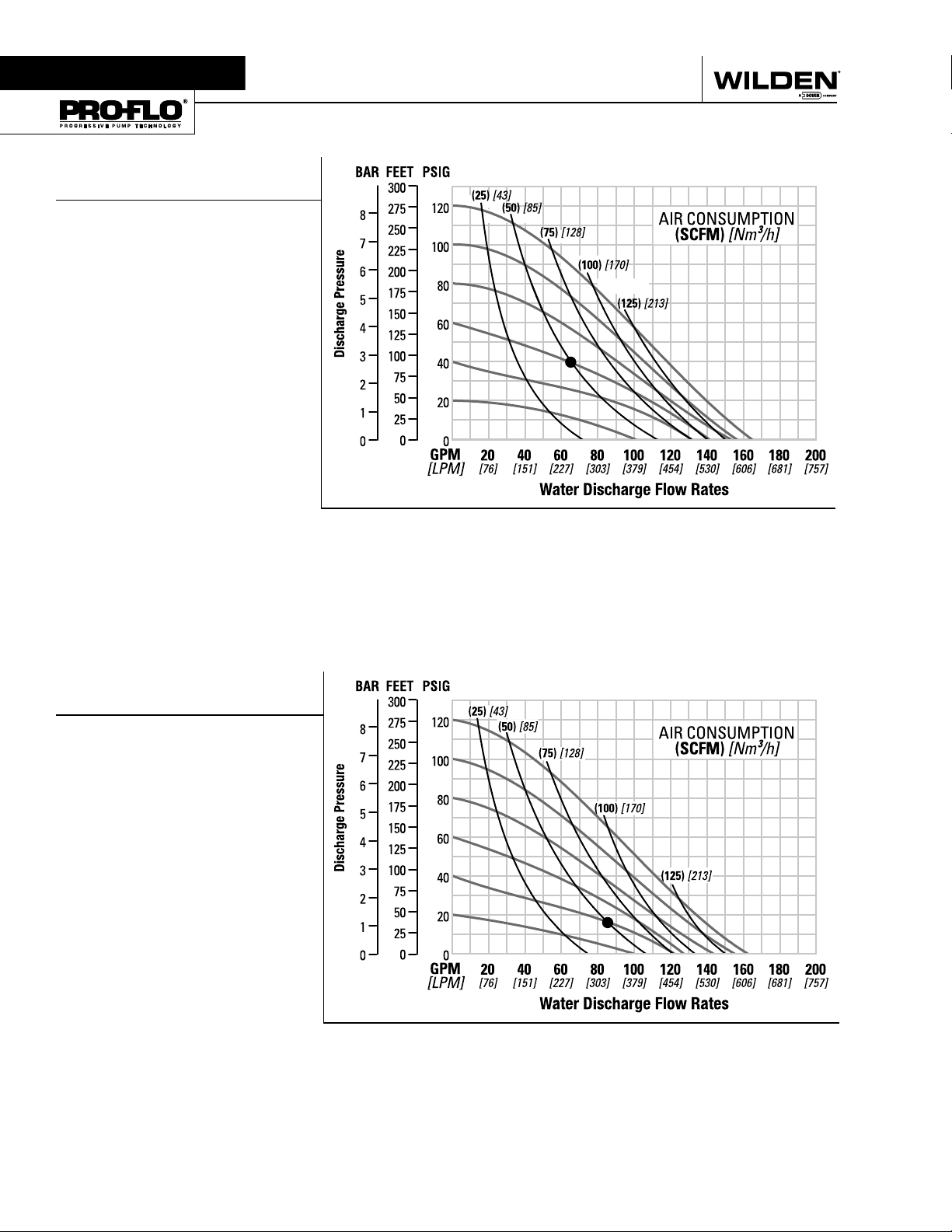
Section 5A
PERFORMANCE
P800 PLASTIC
RUBBER-FITTED
Height ..................................805 mm (31.7")
Width .................................. 605 mm (23.8")
Depth .................................. 353 mm (13.9")
Est. Ship Weight
Polypropylene 32 kg (70 lbs)
PVDF 45 kg (99 lbs)
Air Inlet ....................................13 mm (1⁄2")
Inlet ............................................ 51 mm (2")
Outlet ......................................... 51 mm (2")
Suction Lift ..................... 6.23 m Dry (20.4')
8.65 m Wet (28.4')
Displacement/Stroke 2.75 l (0.727 gal.)
Max. Flow Rate ............ 624 lpm (165 gpm)
Max. Size Solids .....................6.4 mm (1⁄4")
1
Displacement per stroke was calculated at
4.8 Bar (70 psig) air inlet pressure against
a 2 bar (30 psig) head pressure.
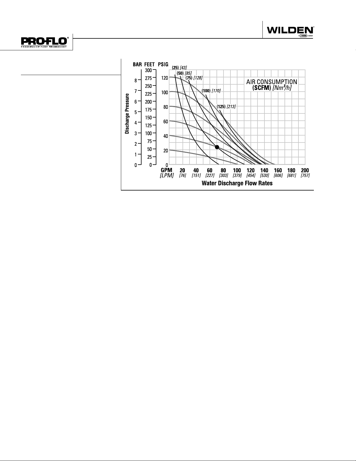
Example: To pump 246 lpm (65 gpm)
against a discharge head pressure of 2.8
Bar (40 psig) requires 4.1 bar (60 psig) and
85 Nm3/h (50 scfm) air consumption. (See
dot on chart.)
Caution: Do not exceed 8.6 bar (125 psig)
air supply pressure.
1
Flow rates indicated on chart were determined by pumping water.
For optimum life and performance, pumps should be specifi ed so that daily operation
parameters will fall in the center of the pump performance curve.
P800 PLASTIC
TPE-FITTED
Height ..................................805 mm (31.7")
Width .................................. 605 mm (23.8")
Depth .................................. 353 mm (13.9")
Est. Ship Weight
Polypropylene 32 kg (70 lbs)
PVDF 45 kg (99 lbs)
Air Inlet ....................................13 mm (1⁄2")
Inlet ............................................ 51 mm (2")
Outlet ......................................... 51 mm (2")
Suction Lift ................... 5.54 m Dry (18.16')
5.19 m Wet (17.0')
Displacement/Stroke .... 2.78 l (0.735 gal.)
Max. Flow Rate ............ 615 lpm (162 gpm)
Max. Size Solids .....................6.4 mm (1⁄4")
1
Displacement per stroke was calculated at
4.8 bar (70 psig) air inlet pressure against a
2 bar (30 psig) head pressure.
Example: To pump 321.8 lpm (85 gpm)
against a discharge head pressure of
1.2 bar (17 psig) requires 2.8 bar (40 psig)
and 85 Nm3/h (50 scfm) air consumption.
(See dot on chart.)
Caution: Do not exceed 8.6 bar (125 psig)
air supply pressure.
1
Flow rates indicated on chart were determined by pumping water.
For optimum life and performance, pumps should be specifi ed so that daily operation
parameters will fall in the center of the pump performance curve.
WILDEN PUMP & ENGINEERING, LLC 6 WIL-11250-E-03
Page 9
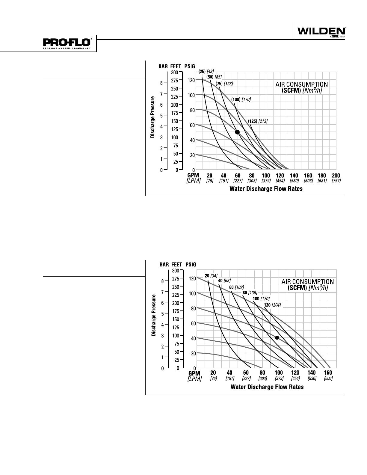
PERFORMANCE
P800 PLASTIC
REDUCED STROKE PTFE-FITTED
Height ..................................805 mm (31.7")
Width .................................. 605 mm (23.8")
Depth .................................. 353 mm (13.9")
Est. Ship Weight
Polypropylene 32 kg (70 lbs)
PVDF 45 kg (99 lbs)
Air Inlet ....................................13 mm (1⁄2")
Inlet ............................................ 51 mm (2")
Outlet ......................................... 51 mm (2")
Suction Lift ................... 4.15 m Dry (13.62')
8.65 m Wet (28.4')
Displacement/Stroke .... 1.73 l (0.457 gal.)
Max. Flow Rate ............ 504 lpm (133 gpm)
Max. Size Solids .....................6.4 mm (1⁄4")
1
Displacement per stroke was calculated at
4.8 bar (70 psig) air inlet pressure against a
2 bar (30 psig) head pressure.
Example: To pump 219.6 lpm (58 gpm)
against a discharge head pressure of 3.4
Bar (50 psig) requires 5.5 bar (80 psig) and
128 Nm3/h (75 scfm) air consumption. (See
dot on chart.)
Caution: Do not exceed 8.6 bar (125 psig)
air supply pressure.
1
Flow rates indicated on chart were determined by pumping water.
For optimum life and performance, pumps should be specifi ed so that daily operation
parameters will fall in the center of the pump performance curve.
P800 PLASTIC
FULL STROKE PTFE-FITTED
Height ................................. 804 mm (31.7”)
Width ..................................604 mm (23.8”)
Depth ..................................353 mm (13.9”)
Ship Weight . Polypropylene 32 kg (70 lbs.)
PVDF 45 kg (99 lbs.)
Air Inlet ...................................13 mm (1/2”)
Inlet ............................................51 mm (2”)
Outlet .........................................51 mm (2”)
Suction Lift ........................ 5.9m Dry (19.5’)
9.0 m Wet (29.5’)
Disp. Per Stroke ................. 2.5 l (0.67 gal.)
Max. Flow Rate ............ 615 lpm (162 gpm)
Max. Size Solids .................... 6.4 mm (1/4”)
1
Displacement per stroke was calculated at
4.8 bar (70 psig) air inlet pressure against a
2.1 bar (30 psig)head pressure.
Example: To pump 98 GPM against a
discharge head of 40 psigrequires 80 psig
and 92 scfm air consumption.
Caution: Do not exceed 8.6 bar (125 psig)
air supply pressure.
1
20 [34]
40 [68]
60 [102]
80 [136]
100 [170]
120 [204]
20 40 60 80 100 120 140 160
[76] [151] [227] [303] [379] [454] [530] [606]
Flow rates indicated on chart were determined by pumping water.
For optimum life and performance, pumps should be specifi ed so that daily operation
parameters will fall in the center of the pump performance curve.
WIL-11250-E-03 7 WILDEN PUMP & ENGINEERING, LLC
Page 10
PERFORMANCE
P800 PLASTIC
ULTRA-FLEX™-FITTED
Height ..................................805 mm (31.7")
Width .................................. 605 mm (23.8")
Depth .................................. 353 mm (13.9")
Est. Ship Weight
Polypropylene 32 kg (70 lbs)
PVDF 45 kg (99 lbs)
Air Inlet ....................................13 mm (1⁄2")
Inlet ............................................ 51 mm (2")
Outlet ......................................... 51 mm (2")
Suction Lift ................... 4.84 m Dry (15.89')
8.65 m Wet (28.4')
Displacement/Stroke .... 1.73 l (0.457 gal.)
Max. Flow Rate ............ 588 lpm (155 gpm)
Max. Size Solids .....................6.4 mm (1⁄4")
1
Displacement per stroke was calculated at
4.8 bar (70 psig) air inlet pressure against a
2 bar (30 psig) head pressure.
Example: To pump 265 lpm (70 gpm)
against a discharge head pressure of
1.7 bar (24 psig) requires 2.8 bar (40 psig)
and 85 Nm3/h (50 scfm) air consumption.
(See dot on chart.)
Caution: Do not exceed 8.6 bar (125 psig)
air supply pressure.
1
Flow rates indicated on chart were determined by pumping water.
For optimum life and performance, pumps should be specifi ed so that daily operation
parameters will fall in the center of the pump performance curve.
WILDEN PUMP & ENGINEERING, LLC 8 WIL-11250-E-03
Page 11
Section 5A
SUCTION LIFT CURVE
P800 PLASTIC
SUCTION LIFT CAPABILITY
WIL-11250-E-03 9 WILDEN PUMP & ENGINEERING, LLC
Page 12

NOTES
Page 13
PX800
P L A S T I C
PX800 PERFORMANCE
WIL-11250-E-03 11 WILDEN PUMP & ENGINEERING, LLC
Page 14
Section 5B
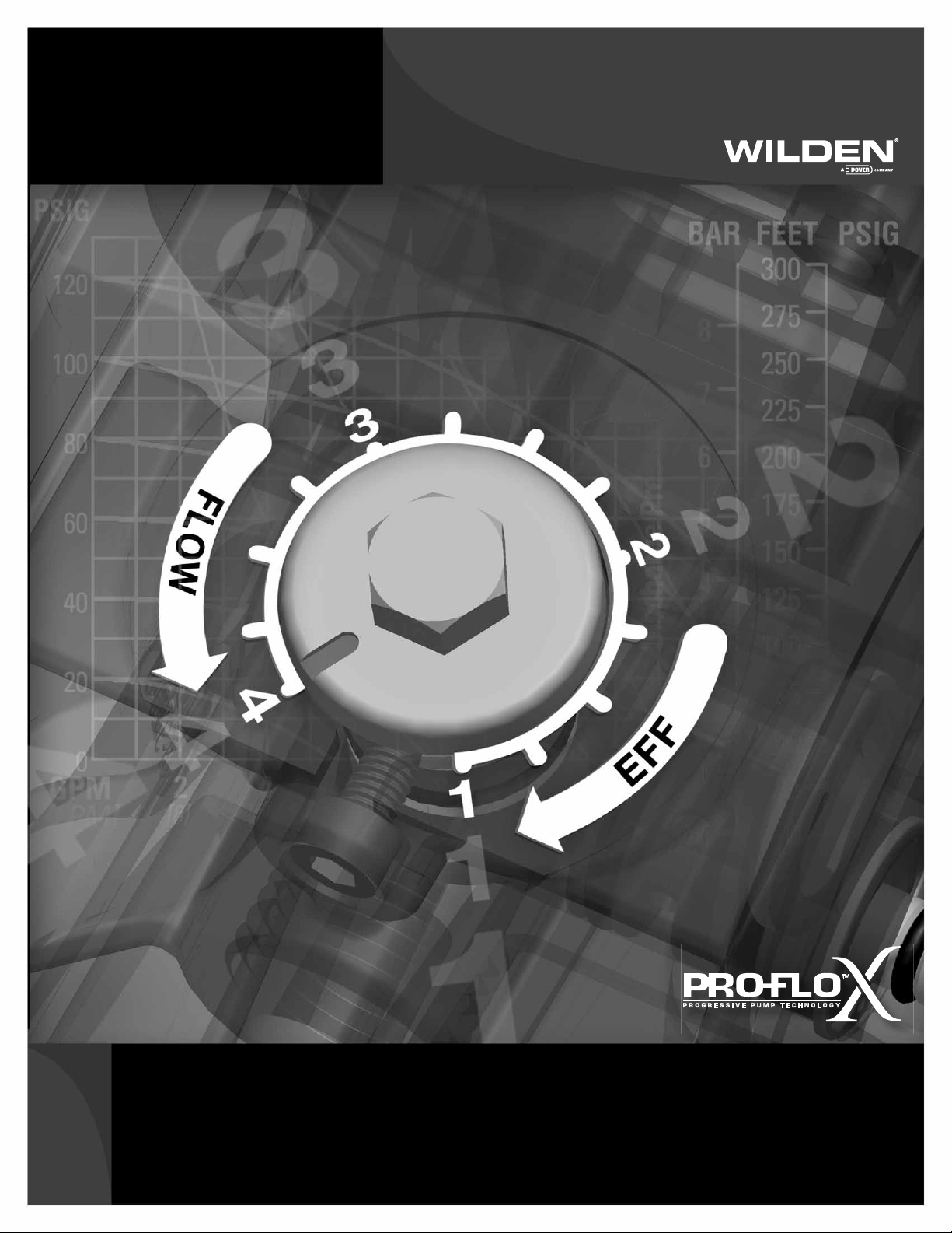
Pro-Flo X
The Pro-Flo X™ air distribution system with the
revolutionary Effi ciency Management System (EMS)
offers fl exibility never before seen in the world of
AODD pumps. The
patent-pending EMS
is simple and easy
to use. With the
turn of an integrated
TM
Operating Principal
control dial, the operator can select the optimal
balance of fl ow and effi ciency that best meets the
application needs. Pro-Flo X™ provides higher
performance, lower
operational costs
and fl exibility that
exceeds previous
industry standards.
AIR CONSUMPTION
$
$
$
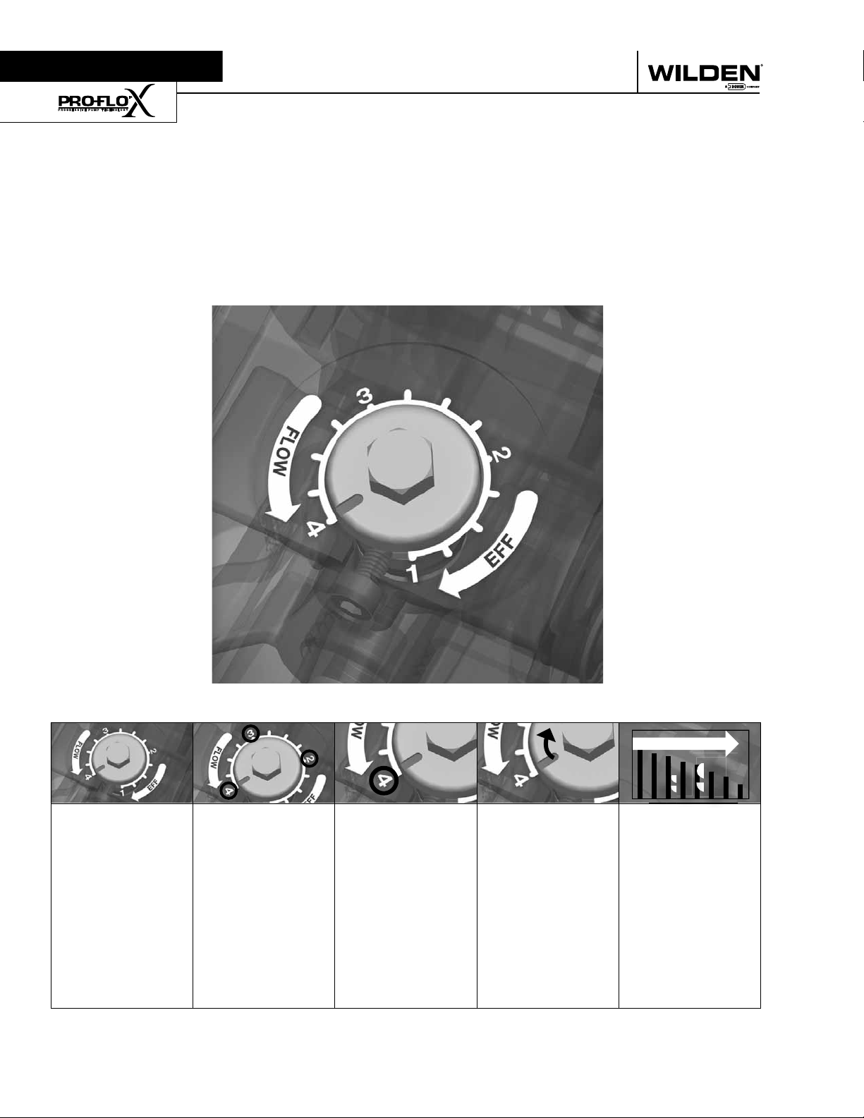
Turning the dial
changes the
relationship
between air inlet
and exhaust
porting.
WILDEN PUMP & ENGINEERING, LLC 12 PX800 Performance
Each dial setting
represents an
entirely different
fl ow curve
Pro-Flo X™ pumps
are shipped from
the factory on
setting 4, which
is the highest
fl ow rate setting
possible
Moving the dial
from setting 4
causes a decrease
in fl ow and an even
greater decrease in
air consumption.
When the air
consumption
decreases more
than the fl ow
rate, effi ciency
is improved and
operating costs
are reduced.
Page 15
Example 1
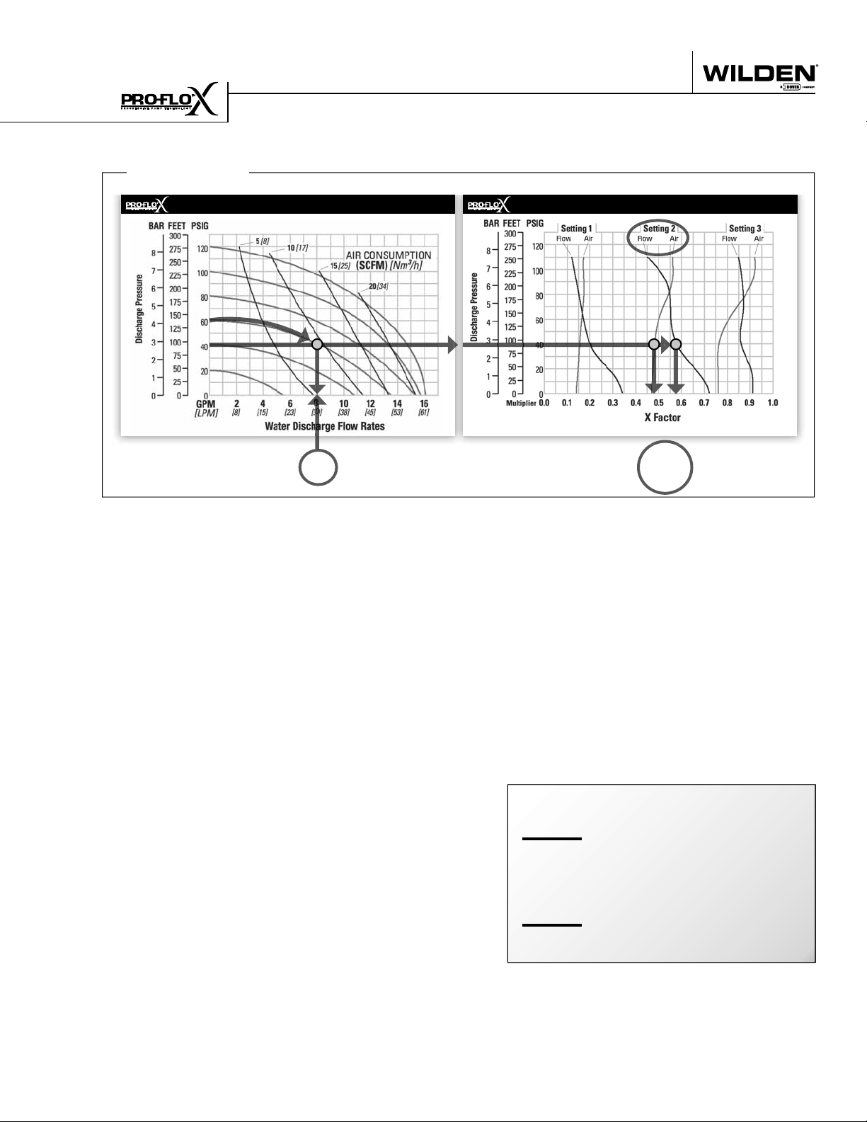
HOW TO USE THIS EMS CURVE
SETTING 4 PERFORMANCE CURVE
Figure 1 Figure 2
Example data point = Example data point =
This is an example showing how to determine fl ow rate and
air consumption for your Pro-Flo X™ pump using the Effi ciency Management System (EMS) curve and the performance
curve. For this example we will be using 4.1 bar (60 psig) inlet
air pressure and 2.8 bar (40 psig) discharge pressure and EMS
setting 2.
Step 1:
Identifying performance at setting 4. Locate
the curve that represents the fl ow rate of the
pump with 4.1 bar (60 psig) air inlet pressure.
Mark the point where this curve crosses the
horizontal line representing 2.8 bar (40 psig)
discharge pressure. (Figure 1). After locating
your performance point on the fl ow curve,
draw a vertical line downward until reaching
the bottom scale on the chart. Identify the fl ow
rate (in this case, 8.2 gpm). Observe location
of performance point relative to air consumption curves and approximate air consumption
value (in this case, 9.8 scfm).
8.2
GPM
curve, draw vertical lines downward until
reaching the bottom scale on the chart. This
identifi es the fl ow X Factor (in this case, 0.58)
and air X Factor (in this case, 0.48).
Step 3:
Calculating performance for specific EMS
setting. Multiply the fl ow rate (8.2 gpm)
obtained in Step 1 by the fl ow X Factor multiplier (0.58) in Step 2 to determine the fl ow rate
at EMS setting 2. Multiply the air consumption (9.8 scfm) obtained in Step 1 by the air
X Factor multiplier (0.48) in Step 2 to determine the air consumption at EMS setting 2
(Figure 3).
gpm
8.2
.58
gpm
4.8
0.58
0.48
(fl ow rate for Setting 4)
(Flow X Factor setting 2)
(Flow rate for setting 2)
EMS CURVE
fl ow multiplier
air multiplier
Step 2:
Determining flow and air X Factors. Locate
your discharge pressure (40 psig) on the vertical axis of the EMS curve (Figure 2). Follow
along the 2.8 bar (40 psig) horizontal line until
intersecting both fl ow and air curves for your
desired EMS setting (in this case, setting 2).
Mark the points where the EMS curves intersect the horizontal discharge pressure line.
After locating your EMS points on the EMS
PX800 Performance 13 WILDEN PUMP & ENGINEERING, LLC
Figure 3
The fl ow rate and air consumption at Setting
2 are found to be 18.2 lpm (4.8 gpm) and 7.9
Nm3/h (4.7 scfm) respectively.
9.8
.48
4.7
scfm
(air consumption for setting 4)
(Air X Factor setting 2)
scfm
(air consumption for setting 2)
Page 16

HOW TO USE THIS EMS CURVE
Example 2.1
SETTING 4 PERFORMANCE CURVE
Figure 4
Example data point =
This is an example showing how to determine the inlet air
pressure and the EMS setting for your Pro-Flo X™ pump to
optimize the pump for a specifi c application. For this example we will be using an application requirement of 18.9 lpm
(5 gpm) fl ow rate against 2.8 bar (40 psig) discharge pressure.
This example will illustrate how to calculate the air consumption that could be expected at this operational point.
10.2
gpm
DETERMINE EMS SETTING
Step 1
: Establish inlet air pressure. Higher air pres-
sures will typically allow the pump to run
more effi ciently, however, available plant air
pressure can vary greatly. If an operating
pressure of 6.9 bar (100 psig) is chosen when
EMS Flow
Settings 1 & 2
0.49
In our example it is 38.6 lpm (10.2 gpm). This
is the setting 4 fl ow rate. Observe the location of the performance point relative to air
consumption curves and approximate air
consumption value. In our example setting
4 air consumption is 24 Nm3/h (14 scfm).
See fi gure 4.
Step 3
: Determine flow X Factor. Divide the required
fl ow rate 18.9 lpm (5 gpm) by the setting 4 fl ow
rate 38.6 lpm (10.2 gpm) to determine the fl ow
X Factor for the application.
5
gpm / 10.2 gpm = 0.49 (flow X Factor)
EMS CURVE
Figure 5
fl ow multiplier
plant air frequently dips to 6.2 bar (90 psig)
Step 4
pump performance will vary. Choose an operating pressure that is within your compressed
air system's capabilities. For this example we
will choose 4.1 bar (60 psig).
: Determine EMS setting from the flow
X Factor. Plot the point representing the fl ow
X Factor (0.49) and the application discharge
pressure 2.8 bar (40 psig) on the EMS curve.
This is done by following the horizontal 2.8
Step 2
: Determine performance point at setting 4. For
this example an inlet air pressure of 4.1 bar
(60 psig) inlet air pressure has been chosen.
Locate the curve that represents the performance of the pump with 4.1 bar (60 psig) inlet
air pressure. Mark the point where this curve
crosses the horizontal line representing 2.8
bar (40 psig) discharge pressure. After locating this point on the fl ow curve, draw a vertical line downward until reaching the bottom
scale on the chart and identify the fl ow rate.
bar (40 psig) psig discharge pressure line until
it crosses the vertical 0.49 X Factor line. Typically, this point lies between two fl ow EMS
setting curves (in this case, the point lies between the fl ow curves for EMS setting 1 and
2). Observe the location of the point relative
to the two curves it lies between and approximate the EMS setting (fi gure 5). For more precise results you can mathematically interpolate between the two curves to determine the
optimal EMS setting.
For this example the EMS setting is 1.8.
WILDEN PUMP & ENGINEERING, LLC 14 PX800 Performance
Page 17

HOW TO USE THIS EMS CURVE
Example 2.2
SETTING 4 PERFORMANCE CURVE
Figure 6
Example data point =
10.2
gpm
Determine air consumption at a specific
EMS setting.
Step 1
: Determine air X Factor. In order to determine
the air X Factor, identify the two air EMS setting curves closest to the EMS setting established in example 2.1 (in this case, the point lies
between the air curves for EMS setting 1 and
2). The point representing your EMS setting
(1.8) must be approximated and plotted on the
EMS curve along the horizontal line representing your discharge pressure (in this case, 40
psig). This air point is different than the fl ow
point plotted in example 2.1. After estimating
(or interpolating) this point on the curve, draw
a vertical line downward until reaching the
bottom scale on the chart and identify the air
X Factor (fi gure 7).
EMS CURVE
EMS Air
Settings 1 & 2
Figure 7
Example data point =
Step 2
: Determine air consumption. Multiply your
setting 4 air consumption (14 scfm) value by
the air X Factor obtained above (0.40) to determine your actual air consumption.
1
4 scfm x 0.40 = 5.6 SCFM
In summary, for an application requiring 18.9 lpm
(5 gpm) against 2.8 bar (40 psig) discharge pressure,
the pump inlet air pressure should be set to 4.1 bar
(60 psig) and the EMS dial should be set to 1.8. The
pump would then consume 9.5 Nm3/h (5.6 scfm) of
compressed air.
0.40
air multiplier
For this example the air X Factor is 0.40
PX800 Performance 15 WILDEN PUMP & ENGINEERING, LLC
Page 18

EMS CURVE
PERFORMANCE
Example:
A PX800 polypropylene, rubber-fi tted pump operating at EMS set-
ting 4, achieved a fl ow rate of 303 lpm (80 gpm) using 88 Nm3/h (52
scfm) of air when run at 4.1 bar (60 psig) air inlet pressure and 2.1
bar (30 psig) discharge pressure (See dot on performance curve).
The end user did not require that much fl ow and wanted to reduce
air consumption at his facility. He determined that EMS setting 1
would meet his needs. At 1.4 bar (20 psig) discharge pressure and
EMS setting 1, the fl ow “X factor” is 0.28 and the air “X factor” is
0.19 (see dots on EMS curve).
Multiplying the original setting 4 values by the “X factors” provides
the setting 1 fl ow rate of 85 lpm (22 gpm) and an air consumption
of 17 Nm3/h (10 scfm). The fl ow rate was reduced by 72% while
the air consumption was reduced by 81%, thus providing increased
effi ciency.
For a detailed example for how to set your EMS, see beginning of
performance curve section.
Caution: Do not exceed 8.6 bar (125 psig) air supply pressure.
The Effi ciency Management System (EMS)
can be used to optimize the performance of
your Wilden pump for specifi c applications.
The pump is delivered with the EMS adjusted
to setting 4, which allows maximum fl ow.
The EMS curve allows the pump user to deter-
mine fl ow and air consumption at each EMS
setting. For any EMS setting and discharge
pressure, the “X factor” is used as a multi-
plier with the original values from the setting
4 performance curve to calculate the actual
fl ow and air consumption values for that spe-
cifi c EMS setting. Note: you can interpolate
between the setting curves for operation at
intermediate EMS settings.
1
SETTING 4 PERFORMANCE CURVE
TECHNICAL DATA
Height . . . . . . . . . . . . . . . . . . . . . . . . . .805 mm (31.7”)
Width. . . . . . . . . . . . . . . . . . . . . . . . . . .605 mm (23.8”)
Depth. . . . . . . . . . . . . . . . . . . . . . . . . . .356 mm (14.0”)
Ship Weight . . . . . . . . Polypropylene 33 kg (70 lbs.)
. . . . . . . . . . . . . . . . . . . . . . . . . . . PVDF 45 kg (99 lbs.)
Air Inlet . . . . . . . . . . . . . . . . . . . . . . . . . . 19 mm (3/4”)
Inlet . . . . . . . . . . . . . . . . . . . . . . . . . . . . . . . 51 mm (2”)
Outlet. . . . . . . . . . . . . . . . . . . . . . . . . . . . . . 51 mm (2”)
Suction Lift . . . . . . . . . . . . . . . . . . . . .6.1 m Dry (19.9’)
. . . . . . . . . . . . . . . . . . . . . . . . . . . . . . 9.0 m Wet (29.5’)
PX800 PLASTIC RUBBER-FITTED
WILDEN PUMP & ENGINEERING, LLC 16 PX800 Performance
Disp. Per Stroke. . . . . . . . . . . . . . . . . 2.6 l (0.70 gal.)
Displacement per stroke was calculated at 4.8 bar (70 psig)
Max. Flow Rate . . . . . . . . . . . . . . .693 lpm (183 gpm)
Max. Size Solids . . . . . . . . . . . . . . . . . . 6.4 mm (1/4”)
1
air inlet pressure against a 2.1 bar (30 psig)head pressure.
Page 19

EMS CURVE
PERFORMANCE
/h (100 scfm)
3
of air when run at 6.9 bar (100 psig) air inlet pressure and 1.4 bar (20
psig) discharge pressure (See dot on performance curve).
The end user did not require that much fl ow and wanted to reduce
air consumption at his facility. He determined that EMS setting 2
would meet his needs. At 1.4 bar (20 psig) discharge pressure and
EXAMPLE
A PX800 polypropylene, TPE-fi tted pump operating at EMS setting 4,
achieved a fl ow rate of 522 lpm (138 gpm) using 170 Nm
EMS setting 2, the fl ow “X factor” is 0.68 and the air “X factor” is
/h (48 scfm). The fl ow rate was reduced by 32% while the
3
0.48 (see dots on EMS curve).
Multiplying the original setting 4 values by the “X factors” provides
the setting 2 fl ow rate of 355 lpm (94 gpm) and an air consumption
of 82 Nm
air consumption was reduced by 52%, thus providing increased ef-
fi ciency.
For a detailed example for how to set your EMS, see beginning of
performance curve section.
Caution: Do not exceed 8.6 bar (125 psig) air supply pressure.
The Effi ciency Management System (EMS)
can be used to optimize the performance of
your Wilden pump for specifi c applications.
The pump is delivered with the EMS adjusted
to setting 4, which allows maximum fl ow.
The EMS curve allows the pump user to deter-
mine fl ow and air consumption at each EMS
setting. For any EMS setting and discharge
pressure, the “X factor” is used as a multi-
plier with the original values from the setting
4 performance curve to calculate the actual
fl ow and air consumption values for that spe-
cifi c EMS setting. Note: you can interpolate
between the setting curves for operation at
intermediate EMS settings.
1
SETTING 4 PERFORMANCE CURVE
TECHNICAL DATA
Height . . . . . . . . . . . . . . . . . . . . . . . . . .805 mm (31.7”)
Width. . . . . . . . . . . . . . . . . . . . . . . . . . .605 mm (23.8”)
Depth. . . . . . . . . . . . . . . . . . . . . . . . . . .356 mm (14.0”)
Ship Weight . . . . . . . . Polypropylene 33 kg (70 lbs.)
. . . . . . . . . . . . . . . . . . . . . . . . . . . PVDF 45 kg (99 lbs.)
Air Inlet . . . . . . . . . . . . . . . . . . . . . . . . . . 19 mm (3/4”)
Inlet . . . . . . . . . . . . . . . . . . . . . . . . . . . . . . . 51 mm (2”)
Outlet. . . . . . . . . . . . . . . . . . . . . . . . . . . . . . 51 mm (2”)
Suction Lift . . . . . . . . . . . . . . . . . . . . .5.4 m Dry (17.6’)
. . . . . . . . . . . . . . . . . . . . . . . . . . . . . . 9.0 m Wet (29.5’)
PX800 PLASTIC TPE-FITTED
PX800 Performance 17 WILDEN PUMP & ENGINEERING, LLC
Disp. Per Stroke. . . . . . . . . . . . . . . . . 2.6 l (0.70 gal.)
Displacement per stroke was calculated at 4.8 bar (70 psig)
Max. Flow Rate . . . . . . . . . . . . . . .689 lpm (182 gpm)
Max. Size Solids . . . . . . . . . . . . . . . . . . 6.4 mm (1/4”)
1
air inlet pressure against a 2.1 bar (30 psig)head pressure.
Page 20

EMS CURVE
PERFORMANCE
.
/h (86 scfm) of air when run at 5.5 bar (80 psig) air inlet pressure and
3
The end user did not require that much fl ow and wanted to reduce
air consumption at his facility. He determined that EMS setting 2
would meet his needs. At 0.7 bar (10 psig) discharge pressure and
EXAMPLE
A PX800 polypropylene, reduced stroke PTFE-fi tted pump operating
at EMS setting 4, achieved a fl ow rate of 439 lpm (116 gpm) using 146
Nm
0.7 bar (10 psig) discharge pressure (See dot on performance curve)
EMS setting 2, the fl ow “X factor” is 0.67 and the air “X factor” is
/h (40 scfm). The fl ow rate was reduced by 33% while the
3
0.46 (see dots on EMS curve).
Multiplying the original setting 4 values by the “X factors” provides
the setting 2 fl ow rate of 294 lpm (78 gpm) and an air consumption
of 67 Nm
air consumption was reduced by 54%, thus providing increased
effi ciency.
For a detailed example for how to set your EMS, see beginning of
performance curve section.
Caution: Do not exceed 8.6 bar (125 psig) air supply pressure.
The Effi ciency Management System (EMS)
can be used to optimize the performance of
your Wilden pump for specifi c applications.
The pump is delivered with the EMS adjusted
to setting 4, which allows maximum fl ow.
The EMS curve allows the pump user to
determine fl ow and air consumption at
each EMS setting. For any EMS setting and
discharge pressure, the “X factor” is used
as a multiplier with the original values from
the setting 4 performance curve to calculate
the actual fl ow and air consumption values
for that specifi c EMS setting. Note: you can
interpolate between the setting curves for
operation at intermediate EMS settings.
1
SETTING 4 PERFORMANCE CURVE
TECHNICAL DATA
Height . . . . . . . . . . . . . . . . . . . . . . . . . .805 mm (31.7”)
Width. . . . . . . . . . . . . . . . . . . . . . . . . . .605 mm (23.8”)
Depth. . . . . . . . . . . . . . . . . . . . . . . . . . .356 mm (14.0”)
Ship Weight . . . . . . . . Polypropylene 33 kg (70 lbs.)
. . . . . . . . . . . . . . . . . . . . . . . . . . . PVDF 45 kg (99 lbs.)
Air Inlet . . . . . . . . . . . . . . . . . . . . . . . . . . 19 mm (3/4”)
Inlet . . . . . . . . . . . . . . . . . . . . . . . . . . . . . . . 51 mm (2”)
Outlet. . . . . . . . . . . . . . . . . . . . . . . . . . . . . . 51 mm (2”)
Suction Lift . . . . . . . . . . . . . . . . . . . . .4.5 m Dry (14.8’)
. . . . . . . . . . . . . . . . . . . . . . . . . . . . . . 7.2 m Wet (23.8’)
PX800 PLASTIC REDUCED STROKE PTFE-FITTED
WILDEN PUMP & ENGINEERING, LLC 18 PX800 Performance
Disp. Per Stroke. . . . . . . . . . . . . . . . . 1.7 l (0.46 gal.)
Displacement per stroke was calculated at 4.8 bar (70 psig)
Max. Flow Rate . . . . . . . . . . . . . . .579 lpm (153 gpm)
Max. Size Solids . . . . . . . . . . . . . . . . . . 6.4 mm (1/4”)
1
air inlet pressure against a 2.1 bar (30 psig)head pressure.
Page 21

EMS CURVE
PERFORMANCE
/h (76
3
scfm) of air when run at 5.5 bar (80 psig) air inlet pressure and 2.1
EXAMPLE
A PX800 plastic, full stroke PTFE fi tted pump operating at EMS set-
bar (30 psig) discharge pressure (See dot on performance curve).
ting 4, achieved a fl ow rate of 416 lpm (110 gpm) using 129 Nm
The end user did not require that much fl ow and wanted to reduce
air consumption at his facility. He determined that EMS setting 3
would meet his needs. At 2.1 bar (30 psig) discharge pressure and
EMS setting 3, the fl ow “X factor” is 0.74 and the air “X factor” is
0.66 (see dots on EMS curve).
/h (50 scfm). The fl ow rate was reduced by 26% while the
3
Multiplying the original setting 4 values by the “X factors” provides
the setting 3 fl ow rate of 308 lpm (81 gpm) and an air consumption
of 85 Nm
air consumption was reduced by 34%, thus providing increased
effi ciency.
For a detailed example for how to set your EMS, see beginning of
performance curve section.
Caution: Do not exceed 8.6 bar (125 psig) air supply pressure.
The Effi ciency Management System (EMS)
can be used to optimize the performance of
your Wilden pump for specifi c applications.
The pump is delivered with the EMS adjusted
to setting 4, which allows maximum fl ow.
The EMS curve allows the pump user to
determine fl ow and air consumption at
each EMS setting. For any EMS setting and
discharge pressure, the “X factor” is used
as a multiplier with the original values from
the setting 4 performance curve to calculate
the actual fl ow and air consumption values
for that specifi c EMS setting. Note: you can
interpolate between the setting curves for
operation at intermediate EMS settings.
SETTING 4 PERFORMANCE CURVE
TECHNICAL DATA
Height . . . . . . . . . . . . . . . . . . . . . . . . . .805 mm (31.7”)
Width. . . . . . . . . . . . . . . . . . . . . . . . . . .605 mm (23.8”)
Depth. . . . . . . . . . . . . . . . . . . . . . . . . . .356 mm (14.0”)
Ship Weight . . . . . . . . Polypropylene 33 kg (70 lbs.)
. . . . . . . . . . . . . . . . . . . . . . . . . . . PVDF 45 kg (99 lbs.)
Air Inlet . . . . . . . . . . . . . . . . . . . . . . . . . . 19 mm (3/4”)
Inlet . . . . . . . . . . . . . . . . . . . . . . . . . . . . . . . 51 mm (2”)
Outlet. . . . . . . . . . . . . . . . . . . . . . . . . . . . . . 51 mm (2”)
Suction Lift . . . . . . . . . . . . . . . . . . . . . 5.9m Dry (19.5’)
. . . . . . . . . . . . . . . . . . . . . . . . . . . . . . 9.0 m Wet (29.5’)
PX800 PLASTIC FULL STROKE PTFE-FITTED
PX800 Performance 19 WILDEN PUMP & ENGINEERING, LLC
Disp. Per Stroke. . . . . . . . . . . . . . . . . 2.5 l (0.67 gal.)1
Displacement per stroke was calculated at 4.8 bar (70 psig)
Max. Flow Rate . . . . . . . . . . . . . 664 lpm (175.4 gpm)
Max. Size Solids . . . . . . . . . . . . . . . . . . 6.4 mm (1/4”)
1
air inlet pressure against a 2.1 bar (30 psig)head pressure.
Page 22

EMS CURVE
PERFORMANCE
EXAMPLE
A PX800 polypropylene, Ultra-Flex-fi tted pump operating at EMS set-
ting 4, achieved a fl ow rate of 220 lpm (58 gpm) using 131 Nm3/h (77
scfm) of air when run at 6.9 bar (100 psig) air inlet pressure and 4.1
bar (60 psig) discharge pressure (See dot on performance curve).
The end user did not require that much fl ow and wanted to reduce
air consumption at his facility. He determined that EMS setting 3
would meet his needs. At 4.1 bar (60 psig) discharge pressure and
EMS setting 3, the fl ow “X factor” is 0.89 and the air “X factor” is
0.81 (see dots on EMS curve).
Multiplying the original setting 4 values by the “X factors” provides
the setting 3 fl ow rate of 195 lpm (52 gpm) and an air consumption
of 106 Nm3/h (62 scfm). The fl ow rate was reduced by 11% while
the air consumption was reduced by 19%, thus providing increased
effi ciency.
For a detailed example for how to set your EMS, see beginning of
performance curve section.
Caution: Do not exceed 8.6 bar (125 psig) air supply pressure.
FITTED
TM
The Effi ciency Management System (EMS)
can be used to optimize the performance of
your Wilden pump for specifi c applications.
The pump is delivered with the EMS adjusted
to setting 4, which allows maximum fl ow.
The EMS curve allows the pump user to deter-
mine fl ow and air consumption at each EMS
setting. For any EMS setting and discharge
pressure, the “X factor” is used as a multi-
plier with the original values from the setting
4 performance curve to calculate the actual
fl ow and air consumption values for that spe-
cifi c EMS setting. Note: you can interpolate
between the setting curves for operation at
intermediate EMS settings.
1
SETTING 4 PERFORMANCE CURVE
TECHNICAL DATA
Height . . . . . . . . . . . . . . . . . . . . . . . . . .805 mm (31.7”)
Width. . . . . . . . . . . . . . . . . . . . . . . . . . .605 mm (23.8”)
Depth. . . . . . . . . . . . . . . . . . . . . . . . . . .356 mm (14.0”)
Ship Weight . . . . . . . . Polypropylene 33 kg (70 lbs.)
. . . . . . . . . . . . . . . . . . . . . . . . . . . PVDF 45 kg (99 lbs.)
Air Inlet . . . . . . . . . . . . . . . . . . . . . . . . . . 19 mm (3/4”)
Inlet . . . . . . . . . . . . . . . . . . . . . . . . . . . . . . . 51 mm (2”)
Outlet. . . . . . . . . . . . . . . . . . . . . . . . . . . . . . 51 mm (2”)
Suction Lift . . . . . . . . . . . . . . . . . . . . .4.8 m Dry (15.9’)
. . . . . . . . . . . . . . . . . . . . . . . . . . . . . . 7.9 m Wet (26.1’)
PX800 PLASTIC ULTRA-FLEX
WILDEN PUMP & ENGINEERING, LLC 20 PX800 Performance
Disp. Per Stroke. . . . . . . . . . . . . . . . . 1.7 l (0.45 gal.)
Displacement per stroke was calculated at 4.8 bar (70 psig)
Max. Flow Rate . . . . . . . . . . . . . . .632 lpm (167 gpm)
Max. Size Solids . . . . . . . . . . . . . . . . . . 6.4 mm (1/4”)
1
air inlet pressure against a 2.1 bar (30 psig) head pressure.
Page 23

Section 5C
SUCTION LIFT CURVE
PX800 PLASTIC
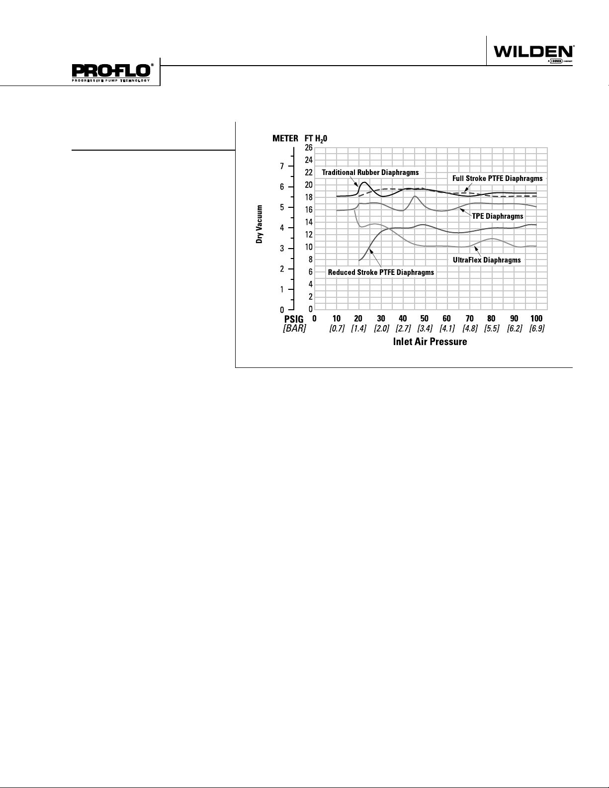
SUCTION LIFT CAPABILITY
Traditional Rubber Diaphragms
TPE Diaphragms
UltraFlex Diaphragms
Reduced Stroke PTFE Diaphragms
Full Stroke PTFE Diaphragms
PX800 Performance 21 WILDEN PUMP & ENGINEERING, LLC
Page 24

T
a
k
e
c
o
n
t
r
o
l
o
f
y
o
u
r
p
r
o
c
e
s
s
t
o
d
a
y
w
i
t
h
22069 Van Buren St. • Grand Terrace, CA 92313-5651
Tel 909-422-1730 • Fax 909-783-3440 • www.wildenx.com
Page 25

Section 6
SUGGESTED INSTALLATION
Wilden pumps are designed to meet the performance
requirements of even the most demanding pumping
applications. They have been designed and manufactured
to the highest standards and are available in a variety of
liquid path materials to meet your chemical resistance
needs. Refer to the performance section of this manual for
an in-depth analysis of the performance characteristics of
your pump. Wilden offers the widest variety of elastomer
options in the industry to satisfy temperature, chemical
compatibility, abrasion resistance and fl ex concerns.
The suction pipe size should be at least the equivalent or
larger than the diameter size of the suction inlet on your
Wilden pump. The suction hose must be non-collapsible,
reinforced type as these pumps are capable of pulling a high
vacuum. Discharge piping should also be the equivalent
or larger than the diameter of the pump discharge which
will help reduce friction losses. It is critical that all fi ttings
and connections are airtight or a reduction or loss of pump
suction capability will result.
INSTALLATION: Months of careful planning, study,
and selection efforts can result in unsatisfactory pump
performance if installation details are left to chance.
Premature failure and long term dissatisfaction can be
avoided if reasonable care is exercised throughout the
installation process.
LOCATION: Noise, safety, and other logistical factors usually
dictate where equipment will be situated on the production
fl oor. Multiple installations with confl icting requirements
can result in congestion of utility areas, leaving few choices
for additional pumps.
Within the framework of these and other existing conditions,
every pump should be located in such a way that six key
factors are balanced against each other to maximum
advantage.
ACCESS: First of all, the location should be accessible. If
it’s easy to reach the pump, maintenance personnel will
have an easier time carrying out routine inspections and
adjustments. Should major repairs become necessary, ease
of access can play a key role in speeding the repair process
and reducing total downtime.
AIR SUPPLY: Every pump location should have an air line
large enough to supply the volume of air necessary to
achieve the desired pumping rate. Use air pressure up to
a maximum of 8.6 bar (125 psig) depending on pumping
requirements.
For best results, the pumps should use a 5µ (micron) air
fi lter, needle valve and regulator. The use of an air fi lter
before the pump will ensure that the majority of any pipeline
contaminants will be eliminated.
SOLENOID OPERATION: When operation is controlled by a
solenoid valve in the air line, three-way valves should be
used. This valve allows trapped air between the valve and
the pump to bleed off which improves pump performance.
Pumping volume can be estimated by counting the number
of strokes per minute and then multiplying the fi gure by the
displacement per stroke.
MUFFLER: Sound levels are reduced below OSHA
specifi cations using the standard Wilden muffl er. Other
muffl ers can be used to further reduce sound levels, but
they usually reduce pump performance.
ELEVATION: Selecting a site that is well within the pump’s
dynamic lift capability will assure that loss-of-prime issues will
be eliminated. In addition, pump effi ciency can be adversely
affected if proper attention is not given to site location.
PIPING: Final determination of the pump site should not be
made until the piping challenges of each possible location
have been evaluated. The impact of current and future
installations should be considered ahead of time to make
sure that inadvertent restrictions are not created for any
remaining sites.
The best choice possible will be a site involving the shortest
and straightest hook-up of suction and discharge piping.
Unnecessary elbows, bends, and fi ttings should be avoided.
Pipe sizes should be selected to keep friction losses within
practical limits. All piping should be supported independently
of the pump. In addition, the piping should be aligned to
avoid placing stress on the pump fi ttings.
Flexible hose can be installed to aid in absorbing the forces
created by the natural reciprocating action of the pump. If the
pump is to be bolted down to a solid location, a mounting
pad placed between the pump and the foundation will assist
in minimizing pump vibration. Flexible connections between
the pump and rigid piping will also assist in minimizing
pump vibration. If quick-closing valves are installed at any
point in the discharge system, or if pulsation within a system
becomes a problem, a surge suppressor (SD Equalizer
should be installed to protect the pump, piping and gauges
from surges and water hammer.
If the pump is to be used in a self-priming application, make
sure that all connections are airtight and that the suction lift is
within the model’s ability. Note: Materials of construction and
elastomer material have an effect on suction lift parameters.
Please refer to the performance section for specifi cs.
When pumps are installed in applications involving fl ooded
suction or suction head pressures, a gate valve should be
installed in the suction line to permit closing of the line for
pump service.
Pumps in service with a positive suction head are most effi cient
when inlet pressure is limited to 0.5–0.7 bar (7–10 psig).
Premature diaphragm failure may occur if positive suction
is 0.7 bar (10 psig) and higher.
SUBMERSIBLE APPLICATIONS: Pro-Flo X™ pumps can be
used for submersible applications, when using the Pro-Flo
X™ single point exhaust option.
NOTE: Pro-Flo
ALL WILDEN PUMPS ARE CAPABLE OF PASSING SOLIDS.
A STRAINER SHOULD BE USED ON THE PUMP INTAKE TO
ENSURE THAT THE PUMP'S RATED SOLIDS CAPACITY IS
NOT EXCEEDED.
CAUTION: DO NOT EXCEED 8.6 BAR (125 PSIG) AIR
SUPPLY PRESSURE.
®
and Accu-Flo™ pumps are not submersible.
®
)
WIL-11250-E-03 23 WILDEN PUMP & ENGINEERING, LLC
Page 26

SUGGESTED INSTALLATION
This illustration is a generic
representation of an air-operated
double-diaphragm pump.
NOTE: In the event of a power failure, the shut off valve
should be closed, if the restarting of the pump is not
desirable once power is regained.
AIR OPERATED PUMPS: To stop the pump from
operating in an emergency situation, simply close the
shut off valve (user supplied) installed in the air supply
line. A properly functioning valve will stop the air supply
to the pump, therefore stopping output. This shut of f
valve should be located far enough away from the
pumping equipment such that it can be reached safely
in an emergency situation.
WILDEN PUMP & ENGINEERING, LLC 24 WIL-11250-E-03
Page 27

SUGGESTED OPERATION & MAINTENANCE
OPERATION: The P800 and PX800 are pre-lubricated,
and do not require in-line lubrication. Additional
lubrication will not damage the pump, however if the
pump is heavily lubricated by an external source, the
pump’s internal lubrication may be washed away. If the
pump is then moved to a non-lubricated location, it may
need to be disassembled and re-lubricated as described
in the ASSEMBLY/DISASSEMBLY INSTRUCTIONS.
Pump discharge rate can be controlled by limiting
the volume and/or pressure of the air supply to the
pump. An air regulator is used to regulate air pressure.
A needle valve is used to regulate volume. Pump
discharge rate can also be controlled by throttling
the pump discharge by partially closing a valve in
the discharge line of the pump. This action increases
friction loss which reduces fl ow rate. (See Section 5.)
Thi s is usefu l whe n the need exis ts to c ontr ol t he pu mp
from a remote location. When the pump discharge
pressure equals or exceeds the air supply pressure,
the pump will stop; no bypass or pressure relief valve
is needed, and pump damage will not occur. The
pump has reached a “deadhead” situation and can
TROUBLESHOOTING
be restarted by reducing the fl uid discharge pressure
or increasing the air inlet pressure. The Wilden P800
and PX800 pumps run solely on compressed air and
do not generate heat, therefore your process fl uid
temperature will not be affected.
MAINTENANCE AND INSPECTIONS: Since each
application is unique, maintenance schedules may
be different for every pump. Frequency of use, line
pressure, viscosity and abrasiveness of process fl uid
all affect the parts life of a Wilden pump. Periodic
inspections have been found to offer the best
means for preventing unscheduled pump downtime.
Personnel familiar with the pump’s construction and
service should be informed of any abnormalities that
are detected during operation.
RECORDS: When service is required, a record should
be made of all necessary repairs and replacements.
Over a period of time, such records can become a
valuable tool for predicting and preventing future
maintenance problems and unscheduled downtime. In
addition, accurate records make it possible to identify
pumps that are poorly suited to their applications.
Pump will not run or runs slowly.
1. Ensure that the air inlet pressure is at least 0.4 bar
(5 psig) above startup pressure and that the differential
pressure (the difference between air inlet and liquid
discharge pressures) is not less than 0.7 bar (10 psig).
2. Check air inlet fi lter for debris (see recommended
installation).
3. Check for extreme air leakage (blow by) which
would indicate worn seals /bores in the air valve,
pilot spool, main shaft.
4. Disassemble pump and check for obstructions
in the air passageways or objects which would
obstruct the movement of internal parts.
5. Check for sticking ball check valves. If material being
pumped is not compatible with pump elastomers,
swelling may occur. Replace ball check valves and
seals with proper elastomers. Also, as the check
valve balls wear out, they become smaller and can
become stuck in the seats. In this case, replace balls
and seats.
6. Check for broken inner piston which will cause the
air valve spool to be unable to shift.
7. Remove plug from pilot spool exhaust.
Pump runs but little or no product fl ows.
1. Check for pump cavitation; slow pump speed
down to allow thick material to fl ow into liquid
chambers.
2. Verify that vacuum required to lift liquid is not
greater than the vapor pressure of the material
being pumped (cavitation).
3. Check for sticking ball check valves. If material being
pumped is not compatible with pump elastomers,
swelling may occur. Replace ball check valves and
seats with proper elastomers. Also, as the check
valve balls wear out, they become smaller and can
become stuck in the seats. In this case, replace balls
and seats.
Pump air valve freezes.
1. Check for excessive moisture in compressed
air. Either install a dryer or hot air generator for
compressed air. Alternatively, a coalescing fi lter
may be used to remove the water from the
compressed air in some applications.
Air bubbles in pump discharge.
1. Check for ruptured diaphragm.
2. Check tightness of outer pistons (refer to Section 7).
3. Check tightness of fasteners and integrity of
o-rings and seals, especially at intake manifold.
4. Ensure pipe connections are airtight.
Product comes out air exhaust.
1. Check for diaphragm rupture.
2. Check tightness of outer pistons to shaft.
WIL-11250-E-03 25 WILDEN PUMP & ENGINEERING, LLC
Page 28

Section 7
PUMP DISASSEMBLY
Tools Required:
• 3/4" Wrench
• Adjustable Wrench
• Vise equipped w/soft jaws
(such as plywood, plastic
or other suitable material)
CAUTION: Before any maintenance or repair is attempted, the compressed air line
to the pump should be disconnected and all air pressure allowed to bleed from the
pump. Disconnect all intake, discharge, and air lines. Drain the pump by turning it
upside down and allowing any fl uid to fl ow into a suitable container. Be aware of
any hazardous effects of contact with your process fl uid.
NOTE: The model photographed for these instructions incorporates PTFE diaphragms,
balls, and seats. Models with rubber diaphragms, balls and seats are the same except
where noted.
Step 1
Please note alignment marks on
liquid chambers. Use to properly
align center section with liquid
chamber.
WILDEN PUMP & ENGINEERING, LLC 26 WIL-11250-E-03
Step 2
Using a 3/4" wrench, loosen the
discharge manifold from the liquid
chambers.
Step 3
Remove the discharge manifold to
expose the valve balls, valve seats
and valve seat o-rings.
Page 29

PUMP DISASSEMBLY
Step 4
Inspect valve balls, valve seats, and
valve seat o-rings for nicks, gouges,
chemical attack or abrasive wear.
Step 5
Using a 3/4" wrench, lossen the inlet
manfold from the liquid chambers.
Step 6
Remove the inlet manifold, valve
balls, valve seats and valve seat
o-rings and inspect for nicks, gouges,
chemical attack or abrasive wear.
Step 7
Using a 3/4" wrench, remove the liquid
chamber fasteners that secure the
liquid chamber to the center section.
WIL-11250-E-03 27 WILDEN PUMP & ENGINEERING, LLC
Step 8
Remove the liquid chamber to expose
the diaphragm and outer piston.
Step 9
Using two adjustable wrenches,
or rotating both diaphragms by
hand (counterclockwise), remove
the diaphragm assembly from the
center section assembly.
Page 30

PUMP DISASSEMBLY
Step 10
Due to varying torque values, one of the
following two situations may occur:
1) The outer piston, diaphragm and
inner piston remain attached to the
shaft and the entire assembly can be
removed from the center section.
2) The outer piston, diaphragm and
inner piston separate from the shaft,
which remains connected to the
opposite side diaphragm assembly.
Step 11
Remove diaphragm assembly from
shaft, secure shaft with soft jaws (a
vise fi tted with plywood, plastic or
other suitable material) to ensure
shaft is not nicked, scratched or
gouged. Using an adjustable wrench
or rotating counterclockwise by
hand, remove diaphragm assembly
from shaft.
WILDEN PUMP & ENGINEERING, LLC 28 WIL-11250-E-03
Page 31

Section 7B
PRO-FLO® AIR DISTRIBUTION SYSTEM (ADS) DISASSEMBLY
Tools Required:
• 3/16" Wrench
• O-ring Pick
CAUTION: Before any maintenance or repair is attempted, the compressed air line
to the pump should be disconnected and all air pressure allowed to bleed from the
pump. Disconnect all intake, discharge, and air lines. Drain the pump by turning it
upside down and allowing any fl uid to fl ow into a suitable container. Be aware of
hazardous effects of contact with your process fl uid.
Step 1
Using a 3/16” hex head wrench,
loosen air valve bolts.
WIL-11250-E-03 29 WILDEN PUMP & ENGINEERING, LLC
Step 2
Remove muffl er plate and air valve
bolts from air valve assembly,
exposing muffl er gasket for
inspection. Replace if necessary.
Step 3
Lift away air valve assembly
and remove air valve gasket for
inspection. Replace if necessary.
Page 32

PRO-FLO® AIR DISTRIBUTION SYSTEM (ADS) DISASSEMBLY
Step 4
Remove air valve end cap to expose
air valve spool by simply lifting up
on end cap once air valve bolts are
removed. Note: Pro-Flo V™ air
valve incorporates an end cap at
both end of the air valve.
Step 5
Remove the air valve spool from the air
valve body by threading one air valve
bolt into the end of the air valve spool
and gently sliding the spool out of the
air valve body. Inspect seals for signs
of wear and replace entire assembly if
necessary. Use caution when handling
air valve spool to prevent damaging
seals. Note: Seals should not be
removed from assembly. Seals are not
sold separately.
Step 6
Remove pilot sleeve from center
section. To do so, the air chambers
must be remove from thecenter
block which will expose the pilot
spool sleeve.
WILDEN PUMP & ENGINEERING, LLC 30 WIL-11250-E-03
Page 33

PRO-FLO® AIR DISTRIBUTION SYSTEM (ADS) DISASSEMBLY
NOTCHED
END
Step 7
Using an o-ring pick, gently remove the o-ring from the opposite side of the
“notched end” on one side of the pilot spool. Gently remove the pilot spool
from pilot spool sleeve and inspect for nicks, gouges and wear. Replace
pilot sleeve or outer sleeve o-rings if necessary. During re-assembly, never
insert the pilot spool into the sleeve with the “notched end” fi rst, this end
incorporates the urethane o-ring and will be damaged as it slides over the
ports cut in the sleeve. Note: Seals should not be removed from pilot
spool. Seals are not sold separately.
Step 8
Inspect center section seals for signs
of wear. If necessary, remove seals
with o-ring pick and replace.
WIL-11250-E-03 31 WILDEN PUMP & ENGINEERING, LLC
Page 34

Section 7C
PRO-FLO X™ AIR DISTRIBUTION SYSTEM (ADS) DISASSEMBLY
Step 1. Figure 1
Loosen the air valve bolts using a 3/16"
hex wrench.
Step 2. Figure 2
Remove air valve bolts, muffl er plate,
and air valve assembly exposing
muffl er gasket and air valve gasket.
Replace if necessary.
Step 3. Figure 3
Remove air valve end cap to expose
the large end of air valve spool by
simply lifting up on the air valve
end cap once the bolts have been
removed.
Step 4. Figure 4
Remove air valve spool from air
valve body by threading one air
valve bolt into the end of the spool
and gently sliding the spool out of
the air valve body. Inspect seals for
signs of wear and replace entire
assembly if necessary. Use caution
when handling air valve spool to
prevent damaging seals.
NOTE: Seals should not be remove
from assembly. Seals are not sold
separately.
WILDEN PUMP & ENGINEERING, LLC 32 WIL-11250-E-03
Step 5. Figure 5
Remove pilot spool retaining snap
ring on both sides of the center
section using snap ring pliers.
Step 6-6A. Figure 6
Remove the air chamber bolts using
a 1/4" hex wrench.
Page 35

PRO-FLO X™ AIR DISTRIBUTION SYSTEM (ADS) DISASSEMBLY
Step 7. Figure 7
Remove the air chamber and inspect
air chamber gaskets (2). Replace if
necessary.
Step 8. Figure 8
Remove the pilot spool from the
center section.
Step 9. Figure 9
With o-ring pick, gently remove the oring from the opposite side of the “center
hole” cut on the spool. Gently remove
the pilot spool from sleeve and inspect
for nicks or gouges and other signs of
wear. Replace pilot sleeve assembly or
outer sleeve o-rings if necessary. During
re-assembly never insert the pilot spool
into the sleeve with the “center cut” side
fi rst, this end incorporates the urethane
o-ring and will be damaged as it slides
over the ports cut in the sleeve.
NOTE: Seals should not be removed
from pilot spool. Seals are not sold
separately.
Step 10. Figure 10
Once the air chambers have been
removed, the square air valve nuts
(6) may be removed or replaced if
necessary.
WIL-11250-E-03 33 WILDEN PUMP & ENGINEERING, LLC
Step 11. Figure 11
Remove and inspect the shaft
bushings (2) replace if necessary.
Step 12. Figure 12
Inspect center block Glyd rings (2)
for wear. If replacement is necessary,
use an o-ring pick to remove the
used Glyd rings then replace with
genuine Wilden replacement parts.
Page 36

Section 7
REASSEMBLY HINTS & TIPS
ASSEMBLY:
Upon performing applicable maintenance to the air
distrib ution system, the p ump can now be reass embled.
Please refer to the disassembly instructions for photos
and parts placement. To reassemble the pump, follow
the disassembly instructions in reverse order. The air
distribution system needs to be assembled fi rst, then
the diaphragms and fi nally the wetted path. Please fi nd
the applicable torque specifi cations on this page. The
following tips will assist in the assembly process.
• Lubricate air valve bore, center section shaft and
pilot spool bore with NLGI grade 2 white EP bearing
grease or equivalent.
• Clean the inside of the center section shaf t bore to
ensure no damage is done to new seals.
• A small amount NLGI grade 2 white EP bearing
grease can be applied to the muffl er and air valve
gaskets to locate gaskets during assembly.
• Make sure that the exhaust port on the muffl er plate
is centered between the two exhaust ports on the
center section.
• Stainless bolts should be lubed to reduce the
possibility of seizing during tightening.
• Use a mallet to tamp lightly on the large clamp
bands to seat the diaphragm before tightening.
PRO-FLO® MAXIMUM TORQUE SPECIFICATIONS
Description of Part Torque
®
Pro-Flo
Air Valve Bolts
Air Chamber to Center Block 27.1 N•m (20 ft-lbs)
Outer Piston, Ultra-Flex™ 47.5 N•m (35 ft-lbs)
Outer Piston, Rubber & TPE 81.3 N•m (60 ft-lbs)
Manifold to Liquid Chamber 44.7 N•m (33 ft-lbs)
Liquid Chamber to Air Chamber 44.7 N•m (33 ft-lbs)
P800 5.1 N•m (45 in-lbs) / PX800 5.1 N•m (45 in-lbs)
SHAFT SEAL INSTALLATION:
PRE-INSTALLATION
• Once all of the old seals have been removed, the
inside of the groove should be cleaned to ensure no
debris is left that may cause premature damage to
the new seals.
INSTALLATION
The following tools can be used to aid in the installation
of the new seals:
Needle Nose Pliers
Phillips Screwdriver
Electrical Tape
• Wrap electrical tape around each leg of the needle nose
pliers (heat shrink tubing may also be used). This is done
to prevent damaging the inside surface of the new seal.
• With a new seal in hand, place the two legs of the needle
nose pliers inside the seal ring. (See Figure A.)
• Open the pliers as wide as the seal diameter will allow,
then with two fi ngers pull down on the top portion of
the seal to form kidney bean shape. (See Figure B.)
• Lightly clamp the pliers together to hold the seal into
the kidney shape. Be sure to pull the seal into as tight
of a kidney shape as possible, this will allow the seal to
travel down the bushing bore easier.
• With the seal clamped in the pliers, insert the seal into
the bushing bore and position the bottom of the seal
into the correct groove. Once the bottom of the seal is
seated in the groove, release the clamp pressure on the
pliers. This will allow the seal to partially snap back to its
original shape.
• Af ter the pliers are removed, you will notice a slight
bump in the seal shape. Before the seal can be properly
resized, the bump in the seal should be removed as
much as possible. This can be done with either the
Phillips screwdriver or your fi nger. With either the side
of the screwdriver or your fi nger, apply light pressure
to the peak of the bump. This pressure will cause the
bump to be almost completely eliminated.
• Lubricate the edge of the shaft with NLGI grade 2
white EP bearing grease.
• Slowly insert the center shaft with a rotating motion.
This will complete the resizing of the seal.
• Perform these steps for the remaining seal.
Figure A
SHAFT SEAL
TAPE
WILDEN PUMP & ENGINEERING, LLC 34 WIL-11250-E-03
Figure B
SHAFT SEAL
NEEDLE NOSE
PLIERS
TAPE
Page 37

ELASTOMER KITS
Program Details:
• Elastomer & ADS Repair Kits
• All Sizes Available
• PTFE, Rubber & TPE Elastomers
• One Part Number Simplifies Inventory
• Eliminates Order Errors
• Reduces Re-Build Time
• Rejuvenates Your Pump
NOTE: See Section 9.
Page 38

Section 8
EXPLODED VIEW AND PARTS LISTING
P800 PLASTIC
FULL STROKE PTFE-FITTED
Full Stroke Diaphragm-Fitted EXPLODED VIEW
A
7
6
5
4
2
3
27
28
29
30
31
32
14
26
17
18
19
A
9
8
21
22
15
23
1
CENTER-PORTED
20
10
11
12
16
34
13
28
33
24
25
33
24
ALL CIRCLED PART IDENTIFIERS ARE INCLUDED IN REPAIR KITS (see section 9).
WILDEN PUMP & ENGINEERING, LLC 36 WIL-11250-E-03
Page 39

EXPLODED VIEW AND PARTS LISTING
P800 PLASTIC
No. Part Description Qty.
1 Pro-Flo® Air Valve Assembly
Full Stroke Diaphragm-Fitted PARTS LISTING
P800/PKPPP
P/N
1
1 04-2000-20-700 04-2000-20-700 04-2000-20-700 04-2000-20-700
P800/KKPPP
P/N
P800/PKPPP-0502
P/N
P800/KKPPP-0502
P/N
2 O-Ring (-225), End Cap (1.859" x .139") 1 04-2390-52-700 04-2390-52-700 04-2390-52-700 04-2390-52-700
3 End Cap, Pro-Flo
®
1 04-2330-20-700 04-2330-20-700 04-2330-20-700 04-2330-20-700
4 Screw, SHC, 1/4-20x4.5” 4 01-6000-03 01-6000-03 01-6000-05 01-6000-05
5 Screw, SHCS, 10-16 x 1.75 2 04-6351-03 04-6351-03 04-6351-03 04-6351-03
6 Muffler Plate, Pro-Flo
®
1 04-3180-20-700 04-3180-20-700 04-3180-20-700 04-3180-20-700
7 Gasket, Muffler Plate 1 04-3500-52-700 04-3500-52-700 04-3500-52-700 04-3500-52-700
8 Gasket, Air Valve 1 04-2600-52-700 04-2600-52-700 04-2600-52-700 04-2600-52-700
9 Center Block 1 04-3110-20 04-3110-20 04-3110-20 04-3110-20
10 Bushing, Reducer 1 04-6950-20-700 04-6950-20-700 04-6950-20-700 04-6950-20-700
11 Nut, Square, 1/4"-20 4 00-6505-03 00-6505-03 00-6505-05 00-6505-05
12 Sleeve, Threaded, Pro-Flo® Center Block 4 04-7710-08 04-7710-08 04-7710-08 04-7710-08
13 Removable Pilot Sleeve Assembly 1 04-3882-99 04-3882-99 04-3882-99 04-3882-99
14 Shaft, Rubber/TPE 1 08-3811-09 08-3811-09 08-3811-09 08-3811-09
15 Glyd™ Ring 2 08-3210-55-225 08-3210-55-225 08-3210-55-225 08-3210-55-225
16 Gasket, Center Block, Pro-Flo
17 Air Chamber, Pro-Flo
®
®
2 04-3526-52 04-3526-52 04-3526-52 04-3526-52
2 08-3681-20 08-3681-20 08-3681-20 08-3681-20
18 Washer, Flat 3/8 x 13/32 8 04-6741-03 04-6741-03 04-6741-03 04-6741-03
19 Screw, HHC, 3/8"-16 x 1-1/4" 8 04-6190-03 04-6190-03 04-6190-03 04-6190-03
20 Inner Piston 2 08-3700-01 08-3700-01 08-3700-01 08-3700-01
21 Diaphragm 2 ****
22 Outer Piston 2 08-4550-21-500 08-4550-21-500 08-4550-21-500 08-4550-21-500
23 Liquid Chamber 2 08-5005-20 08-5005-21 08-5005-20 08-5005-21
24 Washer, Plain 32 04-6730-03 04-6730-03 04-6730-05 04-6730-05
25 Screw, HHC 1/2-13 x 4.00 16 08-6191-03 08-6191-03 08-6191-05 08-6191-05
26 Nut, Hex Flange 1/2-13 16 08-6435-03 08-6435-03 08-6435-05 08-6435-05
27 Screw, HHC 1/2-13 x 2.00 16 04-6210-03 04-6210-03 08-6181-05 08-6181-05
28 Manifold, Discharge ANSI, Side-Ported 1 08-5030-20 08-5030-21 08-5030-20 08-5030-21
Manifold, Discharge DIN, Side Ported 08-5031-20 08-5031-21 08-5031-20 08-5031-21
Manifold, Discharge, Center-Ported, Combo 1 08-5030-20-690 08-5030-21-690 08-5030-20-690 08-5030-21-690
29 Valve Ball 4 ****
30 Valve Seat O-Ring (3.475" x .210") 4 ****
31 Valve Seat 4 08-1125-20 08-1125-21 08-1125-20 08-1125-21
32 Manifold O-ring (4.350"x.210") 4 ****
33 Manifold, Inlet ANSI, Side-Ported 1 08-5090-20 08-5090-21 08-5090-20 08-5090-21
Manifold, Inlet DIN, Side Ported 08-5091-20 08-5091-21 08-5091-20 08-5091-21
Manifold, Inlet, Center-Ported, Combo 1 08-5090-20-690 08-5090-21-690 08-5090-20-690 08-5090-21-690
34 Pilot Spool Retaining O-Ring 2 04-2650-49-700 04-2650-49-700 04-2650-49-700 04-2650-49-700
35 Diaphragm, Full Stroke PTFE, Primary 2 08-1040-55 08-1040-55 08-1040-55 08-1040-55
36 Diaphragm, Full Stroke PTFE, Back-Up 2 08-1065-57 08-1065-57 08-1065-57 08-1065-57
*Refer to Elastometer Chart
1
Air Valve Assembly includes items 2 and 3
0502 Specialty Code = PFA-Coated Hardware
0504 Specialty Code = DIN Flange
All boldface items are primary wear parts.
WIL-11250-E-03 37 WILDEN PUMP & ENGINEERING, LLC
Page 40

EXPLODED VIEW AND PARTS LISTING
P800 PLASTIC
CENTER-PORTED
Reduced Stroke Diaphragm-Fitted EXPLODED VIEW
10
11
12
35
13
16
22
34
29
A
7
6
5
2
4
3
9
15
8
1
B
23 20
ULTRA-FLEX™
WILDEN PUMP & ENGINEERING, LLC 38 WIL-11250-E-03
Page 41

EXPLODED VIEW AND PARTS LISTING
P800 PLASTIC
No. Part Description Qty.
1 Pro-Flo® Air Valve Assembly
Reduced Stroke Diaphragm-Fitted PARTS LISTING
P800/PKPPP
P/N
1
1 04-2000-20-700 04-2000-20-700 04-2000-20-700 04-2000-20-700
P800/KKPPP
P/N
P800/PKPPP-0502
P/N
P800/KKPPP-0502
P/N
2 O-Ring (-225), End Cap (1.859" x .139") 1 04-2390-52-700 04-2390-52-700 04-2390-52-700 04-2390-52-700
3 End Cap, Pro-Flo
®
1 04-2330-20-700 04-2330-20-700 04-2330-20-700 04-2330-20-700
4 Screw, HHC, 1/4-20x4.5” 4 01-6000-03 01-6000-03 01-6000-05 01-6000-05
5 Screw, SHCS, 10-16 x 1.75” 2 04-6351-03 04-6351-03 04-6351-05 04-6351-05
6 Muffler Plate, Pro-Flo
®
1 04-3180-20-700 04-3180-20-700 04-3180-20-700 04-3180-20-700
7 Gasket, Muffler Plate 1 04-3500-52-700 04-3500-52-700 04-3500-52-700 04-3500-52-700
8 Gasket, Air Valve 1 04-2600-52-700 04-2600-52-700 04-2600-52-700 04-2600-52-700
9 Center Block 1 04-3110-20 04-3110-20 04-3100-20 04-3110-20
10 Bushing, Reducer 1 04-6950-20-700 04-6950-20-700 04-6950-20-700 04-6950-20-700
11 Nut, Hex, 1/4"-20 4 00-6505-03 00-6505-03 00-6505-05 00-6505-05
12 Sleeve, Threaded, Pro-Flo® Center Block 4 04-7710-03 04-7710-03 04-7710-03 04-7710-03
13 Removable Pilot Sleeve Assembly 1 04-3882-99 04-3882-99 04-3882-99 04-3882-99
14 Shaft, PTFE 1 08-3842-03 08-3842-03 08-3842-03 08-3842-03
Shaft, Ultra-Flex™ 1 08-3843-03 08-3843-03 08-3843-03 08-3843-03
15 Glyd™ Ring 2 08-3210-55-225 08-3210-55-225 08-3210-55-225 08-3210-55-225
16 Gasket, Center Block, Pro-Flo
17 Air Chamber, Pro-Flo
®
®
2 04-3526-52 04-3526-52 04-3526-52 04-3526-52
2 08-3681-20 08-3681-20 08-3681-20 08-3681-20
18 Washer, flat 3/8 x 13/32 8 04-6741-03 04-6741-03 04-6741-03 04-6741-03
19 Screw, HHC, 3/8"-16 x 1-1/4" 8 04-6190-03 04-6190-03 04-6190-03 04-6190-03
20 Inner Piston 2 08-3750-01 08-3750-01 08-3750-01 08-3750-01
Inner Piston, Ultra-Flex
®
2 08-3761-01 08-3761-01 08-3761-01 08-3761-01
21 Diaphragm, Back-up 2 08-1060-51 08-1060-51 08-1060-51 08-1060-51
Outer Piston, Ultra-Flex™ 2 08-4560-21 08-4560-21 08-4560-21 08-4560-21
22 Diaphragm, PTFE Primary 2 08-1010-55 08-1010-55 08-1010-55 08-1010-55
Diaphragm, Ultra-Flex
TM
2****
23 Outer Piston 2 08-4600-21-500 08-4600-21-500 08-4600-21-500 08-4600-21-500
Outer Piston, Ultra-Flex™ 2 08-4560-21 08-4560-21 08-4560-21 08-4560-21
24 Liquid Chamber 2 08-5005-20 08-5005-21 08-5005-20 08-5005-21
25 Washer, Plain 32 04-6730-03 04-6730-03 04-6730-05 04-6730-05
26 Screw, HHC, 1/2-13 x 4.00 16 08-6191-03 08-6191-03 08-6191-05 08-6191-05
27 Nut, Hex Flange 1/2-13 16 08-6435-03 08-6435-03 08-6435-05 08-6435-05
28 Screw, HHC, 1/2-13 x 2 16 04-6210-03 04-6210-03 08-6181-05 08-6181-05
29 Manifold, Discharge ANSI, Side-Ported 1 08-5030-20 08-5030-21 08-5030-20 08-5030-21
Manifold, Discharge DIN, Side-Ported 1 08-5031-20 08-5031-21 08-5031-20 08-5031-21
Manifold, Discharge, Center-Ported, Combo 1 08-5030-20-690 08-5030-21-690 08-5030-20-690 08-5030-21-690
30 Valve Ball 4 08-1080-55 08-1080-55 08-1080-55 08-1080-55
31 Valve Seat, O-Ring (3.475" x .210") 4 08-1205-60 08-1205-60 08-1205-60 08-1205-60
32 Valve Seat 4 08-1125-20 08-1125-21 08-1125-20 08-1125-21
33 Manifold O-Ring (4.350" x .210") 4 08-1371-60 08-1371-60 08-1371-60 08-1371-60
34 Manifold, Inlet ANSI, Side-Ported 1 08-5090-20 08-5090-21 08-5090-20 08-5090-21
Manifold, Inlet DIN, Side-Ported 1 08-5091-20 08-5010-21 08-5091-20 08-5010-21
Manifold, Inlet, Center-Ported, Combo 1 08-5090-20-690 08-5090-21-690 08-5090-20-690 08-5090-21-690
35 Pilot Spool Retaining O-Ring 2 04-2650-49-700 04-2650-49-700 04-2650-49-700 04-2650-49-700
*Refer to Elastometer Chart
1
Air Valve Assembly includes item numbers 2 and 3
0502 Specialty Code = PFA-Coated Hardware
0504 Specialty Code = DIN Flange
All boldface items are primary wear parts.
WIL-11250-E-03 39 WILDEN PUMP & ENGINEERING, LLC
Page 42

EXPLODED VIEW AND PARTS LISTING
PX800 PLASTIC
FULL STROKE PTFE-FITTED
Full Stroke Diaphragm-Fitted EXPLODED VIEW
CENTER-PORTED
ALL CIRCLED PART IDENTIFIERS ARE INCLUDED IN REPAIR KITS (see section 9).
WILDEN PUMP & ENGINEERING, LLC 40 WIL-11250-E-03
Page 43

PX800 PLASTIC
Item Description Qty.
1 Pro-Flo X™ Assembly, Air Valve
2
O-Ring (-225), End Cap (Ø1.859” x Ø.139”)
3 End Cap 2
4
Screw, SHC, Air Valve (1/4”-20 x 4-1/2”)
5
Nut, Square (1/4”-20)
6 Muffl er Plate, Pro-Flo X™ 1
7
Gasket, Muffl er Plate, Pro-Flo X™
8
Gasket, Air Valve, Pro-Flo X™
9
Center Block Assembly, Pro-Flo X™
10
O-Ring (-210), Adjuster (Ø.734” x Ø.139”)
11
Sleeve, Threaded, Center Block
12 Pilot Spool Retaining O-Ring (Ø.204” x Ø.070”) 2
13
Removable Pilot Sleeve Assembly
14
Shaft Pro-Flo® Rubber Advanced
15 Shaft Seal 2
16 Shaft Bushing 2
17
Gasket, Center Block Pro-Flo V™
18
Air Chamber, Pro-Flo V™
19
Washer, Flat (13/32” x 7/8”))
20
Screw, HHC (3/8”-16 x 1-1/4”)
21
Inner Piston
22
Diaphragm
23
Outer Piston
24
Valve Ball
25
Valve Seat O-Ring (Ø3.475” x Ø.210”)
26
Valve Seat
27
Manifold O-Ring (Ø4.350” x Ø.210”)
28
Liquid Chamber
29
Washer, Plain (17/32” x 1 1/16”)
30
Screw, HHC (1/2” - 13 x 4.00”)
31
Nut, Hex Flange (1/2” - 13)
32
Screw, HHC (1/2” - 13 x 2.00”)
33
Manifold, Discharge, ANSI, Side-Ported
Manifold, Discharge, DIN, Side-Ported
Manifold, Discharge, Center-Ported, Combo
34
Manifold, Inlet, ANSI, Side-Ported
Manifold, Inlet, DIN, Side-Ported
Manifold, Inlet, Center-Ported, Combo
35 Diaphragm, Full Stroke PTFE, Primary 2 08-1040-55 08-1040-55 08-1040-55 08-1040-55
36 Diaphragm, Full Stroke PTFE, Back-Up 2 08-1065-57 08-1065-57 08-1065-57 08-1065-57
Muffler 1” (not Shown)
EXPLODED VIEW AND PARTS LISTING
Full Stroke Diaphragm-Fitted PARTS LISTING
PX800/PKPPP
P/N
1
2
1
2
6
6
1
1
1
1
4
1
1
2
2
8
8
2
2
2
4
4
4
4
2
32
16
16
16
1
1
1
1
1
1
1
08-2030-20 08-2030-20 08-2030-20 08-2030-20
04-2390-52-700 04-2390-52-700 04-2390-52-700 04-2390-52-700
04-2330-20-700 04-2330-20-700 04-2330-20-700 04-2330-20-700
01-6000-03 01-6000-03 01-6000-05 01-6000-05
00-6505-03 00-6505-03 00-6505-05 00-6505-05
08-3185-20 08-3185-20 08-3185-20 08-3185-20
08-3502-52 08-3502-52 08-3502-52 08-3502-52
08-2620-52 08-2620-52 08-2620-52 08-2620-52
08-3126-20 08-3126-20 08-3126-20 08-3126-20
02-3200-52 02-3200-52 02-3200-52 02-3200-52
04-7710-08 04-7710-08 04-7710-08 04-7710-08
04-2650-49-700 04-2650-49-700 04-2650-49-700 04-2650-49-700
04-3882-99 04-3882-99 04-3882-99 04-3882-99
08-3811-09 08-3811-09 08-3811-09 08-3811-09
08-3210-55-225 08-3210-55-225 08-3210-55-225 08-3210-55-225
08-3306-13 08-3306-13 08-3306-13 08-3306-13
04-3529-52 04-3529-52 04-3529-52 04-3529-52
08-3690-20 08-3690-20 08-3690-20 08-3690-20
04-6741-03 04-6741-03 04-6741-03 04-6741-03
04-6190-03 04-6190-03 04-6190-03 04-6190-03
08-3700-01 08-3700-01 08-3700-01 08-3700-01
****
08-4550-21-500 08-4550-21-500 08-4550-21-500 08-4550-21-500
****
****
08-1125-20 08-1125-21 08-1125-20 08-1125-21
****
08-5005-20 08-5005-21 08-5005-20 08-5005-21
04-6730-03 04-6730-03 04-6730-05 04-6730-05
08-6191-03 08-6191-03 08-6191-05 08-6191-05
08-6435-03 08-6435-03 08-6435-05 08-6435-05
04-6210-03 04-6210-03 04-6210-05 04-6210-05
08-5030-20 08-5030-21 08-5030-20 08-5030-21
08-5031-20 08-5031-21 08-5031-20 08-5031-21
08-5030-20-690 08-5030-21-690 08-5030-20-690 08-5030-21-690
08-5090-20 08-5090-21 08-5090-20 08-5090-21
08-5091-20 08-5091-21 08-5091-20 08-5091-21
08-5090-20-690 08-5090-21-690 08-5090-20-690 08-5090-21-690
15-3514-99 15-3514-99 15-3514-99 15-3514-99
PX800/KKPPP
P/N
PX800/PKPPP/ 0502
P/N
PX800/KKPPP 0502
P/N
1
Air Valve Assembly includes items 2 and 3.
2
Center Block Assembly includes items 10, 11, 15 and 16.
0502 Specialty Code=PFA-Coated Hardware
0504 Specialty Code=DIN Flange
*Refer to Elastometer Chart
All boldface items are primary wear parts.
WIL-11250-E-03 41 WILDEN PUMP & ENGINEERING, LLC
Page 44

EXPLODED VIEW AND PARTS LISTING
PX800 PLASTIC
Reduced Stroke Diaphragm-Fitted EXPLODED VIEW
B
23
24 21
ULTRA-FLEX™
ALL CIRCLED PART IDENTIFIERS ARE INCLUDED IN REPAIR KITS (see section 9).
WILDEN PUMP & ENGINEERING, LLC 42 WIL-11250-E-03
Page 45

PX800 PLASTIC
Item Description Qty.
1 Pro-Flo X™ Assembly, Air Valve
2
O-Ring (-225), End Cap (Ø1.859” x Ø.139”)
3 End Cap 2
4
Screw, SHC, Air Valve (1/4”-20 x 4-1/2”)
5
Nut, Square (1/4”-20)
6 Muffl er Plate, Pro-Flo X™ 1
7
Gasket, Muffl er Plate, Pro-Flo X™
8
Gasket, Air Valve, Pro-Flo X™
9
Center Block Assembly, Pro-Flo X™
10
O-Ring (-210), Adjuster (Ø.734” x Ø.139”)
11
Sleeve, Threaded, Center Block
12 Pilot Spool Retaining O-Ring (Ø.204” x Ø.070”) 2
13
Removable Pilot Sleeve Assembly
14
Shaft Pro-Flo® PTFE Advanced
Shaft, Ultra-Flex™ Advanced
15
Shaft Seal
16 Shaft Bushing 2
17 Gasket, Center Block Pro-Flo V™ 2
18
Air Chamber, Pro-Flo V™
19
Washer, Flat (13/32” x 7/8”))
20
Screw, HHC (3/8”-16 x 1-1/4”)
21
Inner Piston
Inner Piston, Ultra-Flex™
22
Diaphragm, Back-up
23
Diaphragm
Diaphragm, Ultra-Flex™
24
Outer Piston
Outer Piston , Ultra-Flex™
25
Valve Ball
26
Valve Seat O-Ring (Ø3.475” x Ø.210”)
27
Valve Seat
28
Manifold O-Ring (Ø4.350” x Ø.210”)
29
Liquid Chamber
30
Washer, Plain (17/32” x 1 1/16”)
31
Screw, HHC (1/2” - 13 x 4.00”)
32
Nut, Hex Flange (1/2” - 13)
33
Screw, HHC (1/2” - 13 x 2.00”)
34
Manifold, Discharge, ANSI, Side-Ported
Manifold, Discharge, DIN, Side-Ported
Manifold, Discharge, Center-Ported, Combo
35
Manifold, Inlet, ANSI, Side-Ported
Manifold, Inlet, DIN, Side-Ported
Manifold, Inlet, Center-Ported, Combo
Muffler 1” (not Shown)
EXPLODED VIEW AND PARTS LISTING
Reduced Stroke Diaphragm-Fitted PARTS LISTING
1
2
PX800/PKPPP
P/N
1
2
6
6
1
1
1
1
4
1
1
1
2
2
8
8
2
2
2
2
2
2
2
4
4
4
4
2
32
16
16
16
1
1
1
1
1
1
1
08-2030-20 08-2030-20 08-2030-20 08-2030-20
04-2390-52-700 04-2390-52-700 04-2390-52-700 04-2390-52-700
04-2330-20-700 04-2330-20-700 04-2330-20-700 04-2330-20-700
01-6000-03 01-6000-03 01-6000-05 01-6000-05
00-6505-03 00-6505-03 00-6505-05 00-6505-05
08-3185-20 08-3185-20 08-3185-20 08-3185-20
08-3502-52 08-3502-52 08-3502-52 08-3502-52
08-2620-52 08-2620-52 08-2620-52 08-2620-52
08-3126-20 08-3126-20 08-3126-20 08-3126-20
02-3200-52 02-3200-52 02-3200-52 02-3200-52
04-7710-08 04-7710-08 04-7710-08 04-7710-08
04-2650-49-700 04-2650-49-700 04-2650-49-700 04-2650-49-700
04-3882-99 04-3882-99 04-3882-99 04-3882-99
08-3842-03 08-3842-03 08-3842-03 08-3842-03
08-3843-03 08-3843-03 08-3843-03 08-3843-03
08-3210-55-225 08-3210-55-225 08-3210-55-225 08-3210-55-225
08-3306-13 08-3306-13 08-3306-13 08-3306-13
04-3529-52 04-3529-52 04-3529-52 04-3529-52
08-3690-20 08-3690-20 08-3690-20 08-3690-20
04-6741-03 04-6741-03 04-6741-03 04-6741-03
04-6190-03 04-6190-03 04-6190-03 04-6190-03
08-3750-01 08-3750-01 08-3750-01 08-3750-01
08-3761-01 08-3761-01 08-3761-01 08-3761-01
08-1060-51 08-1060-51 08-1060-51 08-1060-51
08-1010-55 08-1010-55 08-1010-55 08-1010-55
****
08-4600-21-500 08-4600-21-500 08-4600-21-500 08-4600-21-500
08-4560-21 08-4560-21 08-4560-21 08-4560-21
08-1080-55 08-1080-55 08-1080-55 08-1080-55
08-1205-60 08-1205-60 08-1205-60 08-1205-60
08-1125-20 08-1125-21 08-1125-20 08-1125-21
08-1371-60 08-1371-60 08-1371-60 08-1371-60
08-5005-20 08-5005-21 08-5005-20 08-5005-21
04-6730-03 04-6730-03 04-6730-05 04-6730-05
08-6191-03 08-6191-03 08-6191-05 08-6191-05
08-6435-03 08-6435-03 08-6435-05 08-6435-05
04-6210-03 04-6210-03 04-6210-05 04-6210-05
08-5030-20 08-5030-21 08-5030-20 08-5030-21
08-5031-20 08-5031-21 08-5031-20 08-5031-21
08-5030-20-690 08-5030-21-690 08-5030-20-690 08-5030-21-690
08-5090-20 08-5090-21 08-5090-20 08-5090-21
08-5091-20 08-5091-21 08-5091-20 08-5091-21
08-5090-20-690 08-5090-21-690 08-5090-20-690 08-5090-21-690
15-3514-99 15-3514-99 15-3514-99 15-3514-99
PX800/KKPPP
P/N
PX800/PKPPPP/0502
P/N
PX800/KKPPP/ 0502
P/N
*Refer to Elastometer Chart
1
Air Valve Assembly includes items 2 and 3.
2
Center Block Assembly includes items 10, 11, 15 and 16.
0502 Specialty Code=PFA-Coated Hardware
0504 Specialty Code=DIN Flange
All boldface items are primary wear parts.
WIL-11250-E-03 43 WILDEN PUMP & ENGINEERING, LLC
Page 46

Section 9
ELASTOMER OPTIONS
P800 and PX800 Plastic
MATERIAL
Neoprene 08-1010-51 08-1020-51 08-1060-51 N/A 08-1080-51 N/A N/A N/A
Buna-N 08-1010-52 08-1020-52 N/A N/A 08-1080-52 N/A 08-1205-52 08-1371-52
®
Viton
EPDM 08-1010-54 08-1020-54 N/A N/A 08-1080-54 N/A N/A N/A
PTFE 08-1010-55 N/A N/A N/A 08-1080-55 N/A N/A N/A
Full Stroke PTFE 08-1040-55 N/A N/A N/A N/A N/A N/A N/A
PTFE Encap. (Viton
Polyurethane 08-1010-50 N/A N/A N/A 08-1080-50 N/A N/A N/A
Sanifl ex™ 08-1010-56 N/A 08-1060-56 08-1065-56 08-1080-56 N/A N/A N/A
Wil-Flex™ 08-1010-58 N/A N/A 08-1065-57 08-1080-58 N/A 08-1205-58 08-1371-58
Polypropylene N/A N/A N/A N/A N/A 08-1125-20 N/A N/A
PVDF N/A N/A N/A N/A N/A 08-1125-21 N/A N/A
Back-up diaphragms used with PTFE diaphragms only.
DIAPHRAGMS
(2)
08-1010-53 08-1020-53 N/A N/A 08-1080-53 N/A N/A N/A
®
) N/A N/A N/A N/A N/A N/A 08-1205-60 08-1371-60
ULTRA-FLEX™
DIAPHRAGMS
REDUCED STROKE
BACKUP
DIAPHRAGMS
PRO-FLO® PLASTIC
DESCRIPTION NEOPRENE BUNA-N VITON® EPDM
Pro-Flo® Advanced™ Plastic
08-9553-51 08-9553-52 08-9553-53 08-9553-54 08-9553-55 08-9553-58 08-9553-56 08-9553-50
FULL STROKE
BACKUP
DIAPHRAGMS
VALVE BALLS
(4)
REDUCED
STROKE PTFE WIL-FLEX™ SANIFLEX™
VALVE SEAT
(4)
VALVE SEAT
O-RING (4)
MANIFOLD
O-RING
POLYURETHANE
PRO-FLO X™ PLASTIC
DESCRIPTION NEOPRENE BUNA-N VITON® EPDM
Pro-Flo X™ Advanced™ Plastic
08-9581-51 08-9581-52 08-9581-53 08-9581-54 08-9581-55 08-9581-58 08-9581-56 08-9581-50
REDUCED
STROKE PTFE WIL-FLEX™ SANIFLEX™
POLYURETHANE
WILDEN PUMP & ENGINEERING, LLC 44 WIL-11250-E-03
Page 47

WARRANTY
Each and every product manufactured by Wilden Pump and Engineering, LLC is built to meet the highest
standards of quality. Every pump is functionally tested to insure integrity of operation.
Wilden Pump and Engineering, LLC warrants that pumps, accessories and parts manufactured or supplied by
it to be free from defects in material and workmanship for a period of five (5) years from date of installation or
six (6) years from date of manufacture, whichever comes first. Failure due to normal wear, misapplication, or
abuse is, of course, excluded from this warranty.
Since the use of Wilden pumps and parts is beyond our control, we cannot guarantee the suitability of any pump
or part for a particular application and Wilden Pump and Engineering, LLC shall not be liable for any consequential
damage or expense arising from the use or misuse of its products on any application. Responsibility is limited
solely to replacement or repair of defective Wilden pumps and parts.
All decisions as to the cause of failure are the sole determination of Wilden Pump and Engineering, LLC.
Prior approval must be obtained from Wilden for return of any items for warranty consideration and must be
accompanied by the appropriate MSDS for the product(s) involved. A Return Goods Tag, obtained from an
authorized Wilden distributor, must be included with the items which must be shipped freight prepaid.
The foregoing warranty is exclusive and in lieu of all other warranties expressed or implied (whether written or oral)
including all implied warranties of merchantability and fitness for any particular purpose. No distributor or other
person is authorized to assume any liability or obligation for Wilden Pump and Engineering, LLC other than expressly
provided herein.
PLEASE PRINT OR TYPE AND FAX TO WILDEN
PUMP INFORMATION
Item # Serial #
Company Where Purchased
YOUR INFORMATION
Company Name
Industry
Name Title
Street Address
City State Postal Code Country
Telephone Fax E-mail Web Addre ss
Number of pumps in facility? Number of Wilden pumps?
Types of pumps in facility (check all that apply): Diaphragm
Media being pumped?
Other
Centrifugal
Gear
Submersible
Lobe
How did you hear of Wilden Pump?
Other
NOTE: WARRANTY VOID IF PAGE IS NOT FAXED TO WILDEN
Trade Journal
Trade Show
ONCE COMPLETE, FAX TO (909) 783-3440
WILDEN PUMP & ENGINEERING, LLC
Internet/E-mail
Distributor
 Loading...