

Wilden P400, PX400 Engineering, Operation & Maintenance
EOM
Engineering
Operation &
Maintenance
P400/PX400
Plastic Pump
Where Innovation Flows
www.wildenpump.com
TABLE OF CONTENTS
SECTION 1 CAUTIONS—READ FIRST! .............................................1
SECTION 2 WILDEN PUMP DESIGNATION SYSTEM ................................2
SECTION 3 HOW IT WORKS—PUMP & AIR DISTRIBUTION SYSTEM. . . . . . . . . . . . . . . . 3
SECTION 4 DIMENSIONAL DRAWINGS .............................................4
SECTION 5 PERFORMANCE
A. P400 Plastic Performance Curves
Rubber-Fitted ....................................................... 6
TPE-Fitted .......................................................... 6
Reduced-Stroke PTFE-Fitted .......................................... 7
Full-Stroke PTFE-Fitted ............................................... 7
Suction-Lift Curves .................................................... 8
B. PX400 Plastic Performance
Operating Principle ....................................................10
How to Use this EMS Curve .............................................11
Perf orman c e Cur ve s
Rubber-Fitted ....................................................14
TPE-Fitted .......................................................15
Reduced-Stroke PTFE-Fitted ........................................16
Full-Stroke PTFE-Fitted ............................................17
Suction-Lift Curves ....................................................18
SECTION 6 SUGGESTED INSTALLATION, OPERATION & TROUBLESHOOTING ......19
SECTION 7 DISASSEMBLY / REASSEMBLY ........................................22
Pro-Flo® Air Valve / Center Section Disassembly ...............................25
Pro-Flo X
Reassembly Hints & Tips ..................................................30
TM
Air Valve / Center Section Disassembly .............................28
SECTION 8 EXPLODED VIEW & PARTS LISTING
P400 Plastic .............................................................32
PX400 Plastic ...........................................................34
SECTION 9 ELASTOMER OPTIONS ................................................36
Section 1
CAUTIONS—READ FIRST!
CAUTION: Do not apply compressed air to the
exhaust port — pump will not function.
CAUTION: Do not over-lubricate air supply —
excess lub rication will reduce pump perfor mance.
Pump is pre-lubed.
TEMPERATURE LIMITS:
Acetal –29°C to 82°C –20°F to 180°F
Buna-N –12°C to 82°C 10°F to 180°F
Geolast
®
–40°C to 82°C –40°F to 180°F
Neoprene –18°C to 93°C 0°F to 200°F
Nordel
®
EPDM –51°C to 138°C –60°F to 280°F
Nylon –18°C to 93°C 0°F to 200°F
PFA –7°C to 107°C 45°F to 225°F
Polypropylene 0°C to 79°C 32°F to 175°F
Polyurethane –12°C to 66°C 10°F to 150°F
PVDF –12°C to 107°C 10°F to 225°F
Saniflex™ –29°C to 104°C –20°F to 220°F
SIPD PTFE with EPDM-backed
SIPD PTFE with Neoprene-backed
PTFE
Viton
1
4°C to 104°C 40°F to 220°F
®
FKM –40°C to 177°C –40°F to 350°F
4°C to 137°C 40°F to 280°F
4°C to 93°C 40°F to 200°F
Wil-Flex™ –40°C to 107°C –40°F to 225°F
1
4°C to 149°C (40°F to 300°F) - 13 mm (1/2") and 25 mm (1") models only.
NOTE: Not all materials are available for all
models. Refer to Section 2 for material options
for your pump.
CAUTION: When choosing pump materials, be
sure to check the temperature limits for all wetted
components. Example: Viton® has a maximum
limit of 177°C (350°F) but polypropylene has a
maximum limit of only 79°C (175°F).
CAUTION: Maximum temperature limits are
based upon mechanical stress only. Certain
chemicals will significantly reduce maximum
safe operating temperatures. Consult Chemical
Resistance Guide for chemical compatibility and
temperature limits.
WARNING : Prevent static sparking — If static
sparking occurs, fire or explosion could result.
Pump, valves, and containers must be grounded
to a proper grounding point when handling
flammable fluids and whenever discharge of
static electricity is a hazard.
CAUTION: Do not exceed 8.6 bar (125 psig) air
supply pressure.
CAUTION: Do not exceed 82°C (180°F) air inlet
temperature for Pro-Flo X™ models.
CAUTION: Pumps should be thoroughly flushed
before installing into process lines. FDA- and
USDA-approved pumps should be cleaned and/
or sanitized before being used.
CAUTION: Always wear safety glasses when
operating pump. If diaphragm rupture occurs,
material being pumped may be forced out air
exhaust.
CAUTION: Before any maintenance or repair is
attempted, the compressed air line to the pump
should be disconnected and all air pressure
allowed to bleed from pump. Disconnect all
intake, discharge and air lines. Drain the pump
by turning it upside down and allowing any fluid
to flow into a suitable container.
CAUTION: Blow out air line for 10 to 20 seconds
before attaching to pump to make sure all
pipeline debris is clear. Use an in-line air filter. A
5μ (micron) air filter is recommended.
NOTE: When installing PFTE diaphragms, it is
important to tighten outer pistons simultaneously
(turning in opposite directions) to ensure tight fit.
(See torque specifications in Section 7.)
NOTE: PVDF pumps come standard from the
factory with expanded PTFE gaskets installed
in the diaphragm bead of the liquid chamber,
in the T-section and in the ball and seat area.
PTFE gaskets cannot be re-used. Consult for
installation instructions during reassembly.
NOTE: Before starting disassembly, mark a line
from each liquid chamber to its corresponding air
chamber. This line will assist in proper alignment
during reassembly.
CAUTION: Pro-Flo® pumps cannot be used in
submersible applications. Pro-Flo X™ is available
in both single-point exhaust (submersible) and
standard (non-submersible) options. Do not use
standard Pro-Flo X™ models in submersible
applications. Turbo-Flo™ pumps are also
available in a single-point exhaust (submersible)
configuration.
CAUTION: The process fluid and cleaning fluids
CAUTION : Tighten all hardware prior to installation.
must be chemically compatible with all wetted
pump components. Consult Chemical Resistance
Guide.
WIL-11240-E-05 1 WILDEN PUMP & ENGINEERING, LLC
Section 2
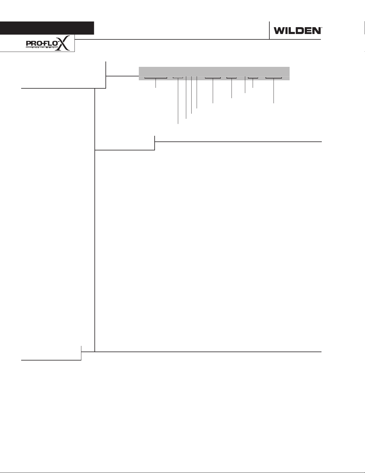
WILDEN PUMP DESIGNATION SYSTEM
P400/PX400
PLASTIC
38 mm (1-1/2") Pump
Maximum Flow Rate:
450 lpm (119 gpm)
LEGEND
PX400 / XXXXX / XXX / XX / XXX / XXXX
MODEL
MATERIAL CODES
MODEL
P400 = PRO‑FLO
PX400 = PRO‑FLO X™
WETTED PARTS & OUTER PISTON
KK = PVDF / PVDF
KZ = PVDF / NO OUTER PISTON
PP = POLYPROPYLENE /
POLYPROPYLENE
PZ = POLYPROPYLENE / NO
OUTER PISTON
AIR CHAMBERS
P = POLYPROPYLENE
CENTER BLOCK
P = POLYPROPYLENE
AIR VALVE
P = POLYPROPYLENE
®
DIAPHRAGMS
VALVE BALLS
AIR VALVE
CENTER BLOCK
AIR CHAMBERS
WETTED PARTS & OUTER PISTON
DIAPHRAGMS
BNS = BUNA‑N (Red Dot)
EPS = EPDM (Blue Dot)
FSS = SANIFLEX™
[Hytrel® (Cream)]
FWL = SANITARY WIL‑FLEX™,
IPD
FWS = SANITARY WIL‑FLEX™,
EZ‑INSTALL [Santoprene®
(Two Orange Dots)]
NES = NEOPRENE (Green Dot)
PUS = POLYURETHANE (Clear)
TEU = PTFE W/EPDM
BACK‑UP (White)
TNU = PTFE W/NEOPRENE
BACK‑UP (White)
TSS = FULL STROKE PTFE
W/SANIFLEX™ BACK‑UP
TSU = PTFE W/SANIFLEX™
BACK‑UP (White)
TWS = FULL STROKE PTFE
W/WIL‑FLEX™ BACK‑UP
VTS = VITON® (White Dot)
WFS = WIL‑FLEX™ [Santoprene®
(Orange Dot)]
ZGS = GEOLAST®, EZ‑INSTALL
ZPS = POLYURETHANE,
EZ‑INSTALL
ZSS = SANIFLEX™, EZ‑INSTALL
ZWL = WIL‑FLEX™, INTEGRAL
PISTON
ZWS = WIL‑FLEX™, EZ‑INSTALL
O-RINGS
VALVE SE ATS
VALVE BALLS
BN = BUNA‑N (Red Dot)
EP = EPDM (Blue Dot)
FS = SANIFLEX™
FW = SANITARY WIL‑FLEX™
NE = NEOPRENE (Green Dot)
PU = POLYURETHANE (Clear)
TF = PTFE (White)
VT = VITON® (White Dot)
WF = WIL‑FLEX™ [Santoprene®
VALVE SEATS
K = PVDF
P = POLYPROPYLENE
VALVE SEAT O-RINGS
BN = BUNA‑N
TV = PTFE ENCAP. VITON
WF = WIL‑FLEX™ (Santoprene®)
SPECIALT Y
CODE
(if applicable)
[Hytrel® (Cream)]
[Santoprene® (Two Orange
Dots)]
(Orange Dot)]
®
SPECIALTY CODES
0100 Wil‑Gard II™ 110V
0102 Wil‑Gard II™, sensor wires ONLY
0103 Wil‑Gard II™ 220V
0320 Single‑point exhaust
0502 PFA‑coated hardware
0504 DIN flange
0506 DIN flange, PFA coated hardware
0604 DIN flange Wil‑Gard II™ 220V
NOTE: Most elastomeric materials use colored dots for identification.
Viton® is a registered trademark of DuPont Dow Elastomers.
WILDEN PUMP & ENGINEERING, LLC 2 WIL-11240-E-05
Section 3
HOW IT WORKS—PUMP
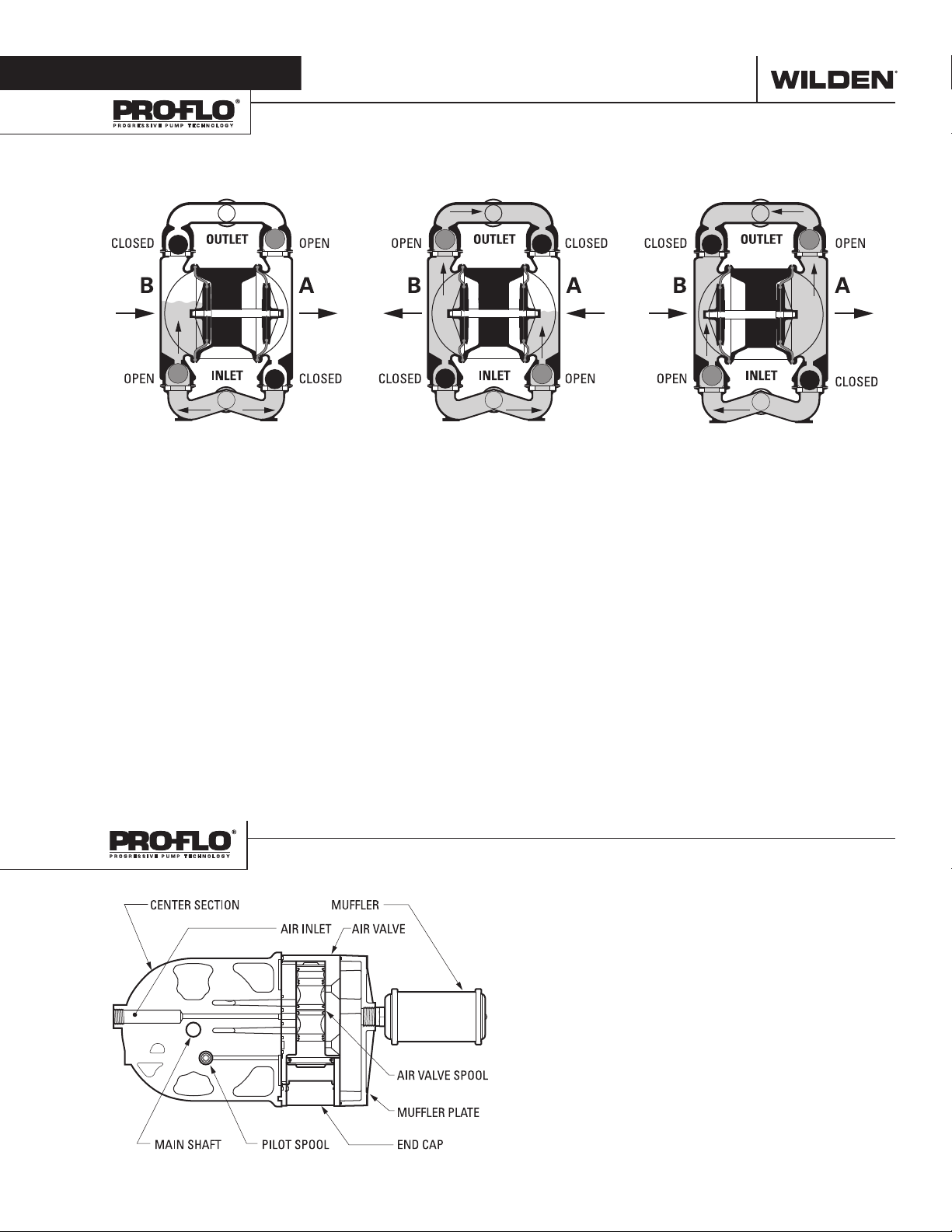
The Wilden diaphragm pump is an air-operated, positive displacement, self-priming pump. These drawings show flow pattern
through the pump upon its initial stroke. It is assumed the pump has no fluid in it prior to its initial stroke.
FIGUR E 1 The air valve dire cts pre ssurized
air to the back side of diaphragm A. The
compressed air is applied directly to the
liquid column separated by elastomeric
diaphragms. The diaphragm acts as
a separation membrane between the
compressed air and liquid; a balanced
load removes mechanical stress from the
diaphragm. The compressed air moves
the diaphragm away from the center
of the pump. The opposite diaphragm
is pulled in by the shaft connected to
the pressurized diaphragm. Diaphragm
B is on its suction stroke; air behind
the diaphragm has been forced out to
atmosphere through the exhaust por t of
the pump. The movement of diaphragm
B toward the center of the pump creates
a vacuum within chamber B. Atmos pheric
pressure forces fluid into the inlet
manifold forcing the inlet valve ball off its
seat. Liquid is free to move past the inlet
valve ball and fill the liquid chamber (see
shaded area).
HOW IT WORKS—AIR DISTRIBUTION SYSTEM
FIGURE 2 When the pressurized diaphragm,
diaphra gm A, re aches t he limit of it s disc harge
stroke, the air valve redirects pressurized
air to the back side of diaphragm B. The
pressurized air forces diaphragm B away
from the center while pulling diaphragm A
to the center. Diaphragm B is now on its
discharge stroke. Diaphragm B forces the
inlet valve ball onto its seat due to the
hydraulic forces developed in the liquid
chamber and manifold of the pump. These
same hydraulic forces lift the discharge
valve ball off its seat, while the opposite
discharge valve ball is forced onto its seat,
forcing fluid to flow through the pump
discharge. The movement of diaphragm A
toward the center of the pump creates a
vacuum within liquid chamber A. Atmospheric pressure forces fluid into the inlet
manifold of the pump. The inlet valve ball
is forced off its seat allowing the fluid being
pumped to fill the liquid chamber.
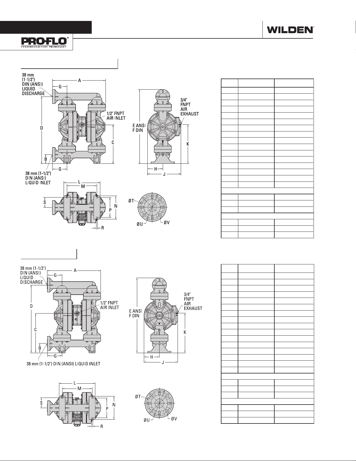
The Pro-Flo
moving parts: the air valve spool and the pilot spool. The heart of
the system is the air valve spool and air valve. This valve design
incorporates an unbalanced spool. The smaller end of the spool
is pressurized continuously, while the large end is alternately
pressurized then exhausted to move the spool. The spool directs
pressurized air to one air chamber while exhausting the other.
The air causes the main shaft/diaphragm assembly to shif t to
one side — discharging liquid on that side and pulling liquid in
on the other side. When the shaf t reaches the end of its stroke,
the inner piston actuates the pilot spool, which pressurizes and
exhausts the large end of the air valve spool. The repositioning
of the air valve spool routes the air to the other air chamber.
®
patented air distribution system incorporates two
FIGURE 3 At completion of the stroke,
the air valve again redirec ts air to the
back side of diaphragm A, which star ts
diaphragm B on its exhaust stroke. As
the pump reaches its original starting
point, each diaphragm has gone through
one exhaust and one discharge stroke.
This constitutes one complete pumping
cycle. The pump may take several cycles
to completely prime depending on the
conditions of the application.
WIL-11240-E-05 3 WILDEN PUMP & ENGINEERING, LLC
Section 4
DIMENSIONAL DRAWINGS
P400 Polypropylene
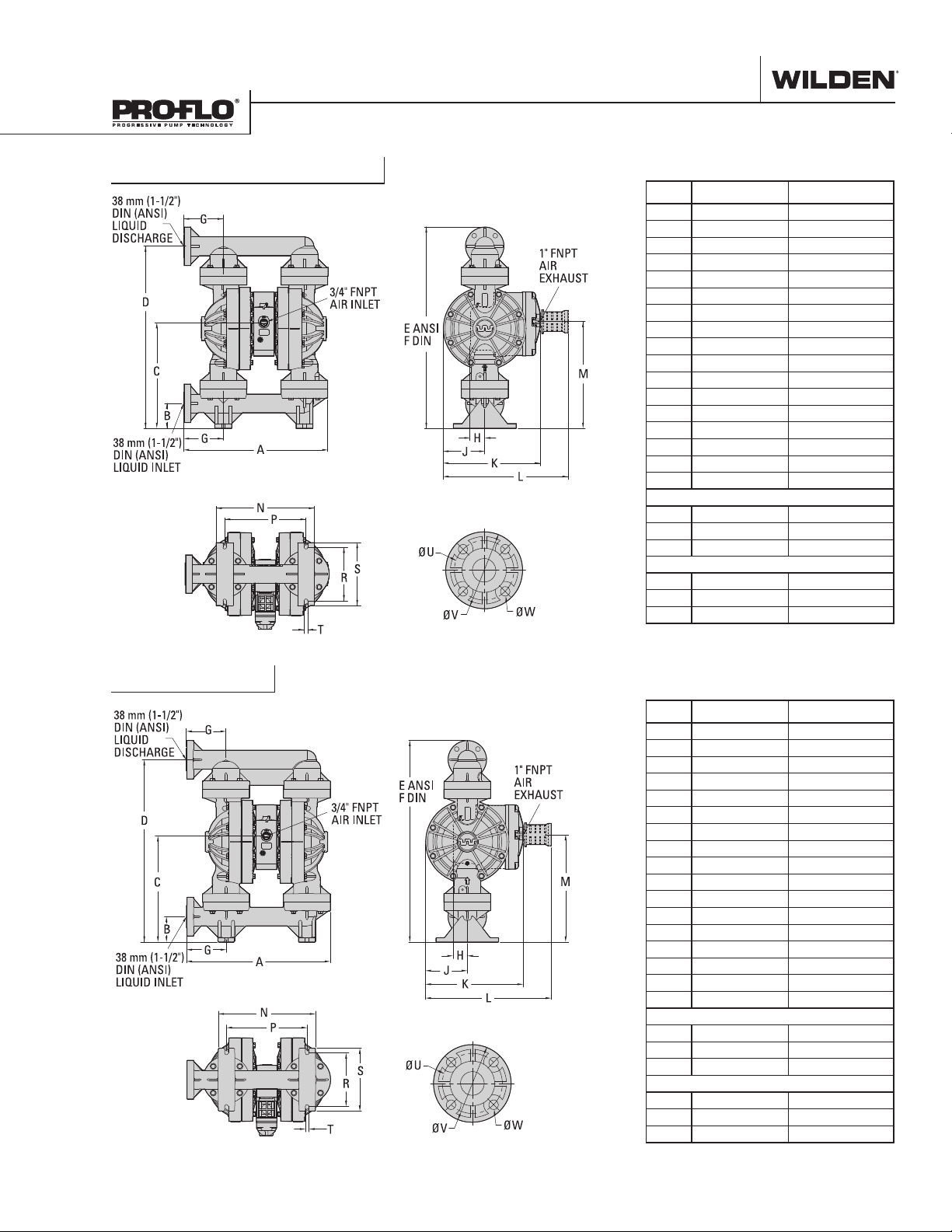
DIMENSIONS
ITEM METRIC (mm) STANDARD (inch)
A 476 18.8
B 81 3.2
C 348 13.7
D 602 23.7
E 665 26.2
F 677 26.6
G 131 5.2
H 138 5.4
J 300 11.8
K 351 13.8
L 324 12.8
M 268 10.6
N 208 8.2
P 176 6.9
R 12 0.5
S 91 3.6
DIN FL ANGE
T 110 DIA. 4.3 DIA.
U 150 DIA. 5.9 DIA.
V 18 DIA. 0.7 DIA.
ANSI FLANGE
T 98 DIA. 3.9 DIA.
U 127 DIA. 5.0 DIA.
V 16 DIA. 0.6 DIA.
LW0324 REV. A
P400 PVDF
DIMENSIONS
ITEM METRIC (mm) STANDARD (inch)
A 471 18.5
B 83 3.2
C 345 13.6
D 596 23.4
E 659 25.9
F 670 26.4
G 130 5.1
H 137 5.4
J 300 11.8
K 348 13.7
L 319 12.6
M 264 10.4
N 205 8.1
P 174 6.9
R 12 0.5
S 91 3.6
DIN FL ANGE
T 110 DIA. 4.3 DIA.
U 149 DIA. 5.9 DIA.
V 18 DIA. 0.7 DIA.
ANSI FLANGE
T 98 DIA. 3.9 DIA.
U 126 DIA. 5.0 DIA.
V 16 DIA. 0.6 DIA.
LW0325 REV. A
WILDEN PUMP & ENGINEERING, LLC 4 WIL-11240-E-05
DIMENSIONAL DRAWINGS
PX400 Polypropylene
DIMENSIONS
ITEM METRIC (mm) STANDARD (inch)
A 476 18.8
B 82 3.2
C 348 13.7
D 602 23.7
E 665 26.2
F 677 26.6
G 131 5.2
H 48 1.9
J 138 5.4
K 320 12.6
L 411 16.2
M 356 14.0
N 324 12.8
P 268 10.6
R 176 6.9
S 208 8.2
T 12 0.5
DIN FL ANGE
U 110 DIA. 4.3 DIA.
V 150 DIA. 5.9 DIA.
W 18 DIA. 0.7 DIA.
ANSI FLANGE
U 98 DIA. 3.9 DIA.
V 127 DIA. 5.0 DIA.
W 16 DIA. 0.6 DIA.
LW0326 REV. A
PX400 PVDF
DIMENSIONS
ITEM METRIC (mm) STANDARD (inch)
A 471 18.5
B 83 3.2
C 345 13.6
D 596 23.4
E 659 25.9
F 670 26.4
G 130 5.1
H 48 1.9
J 137 5.4
K 320 12.6
L 411 16.2
M 351 13.8
N 319 12.6
P 264 10.4
R 174 6.9
S 205 8.1
T 12 0.5
DIN FL ANGE
U 110 DIA. 4.3 DIA.
V 149 DIA. 5.9 DIA.
W 18 DIA. 0.7 DIA.
ANSI FLANGE
U 98 DIA. 3.9 DIA.
V 126 DIA. 5.0 DIA.
W 16 DIA. 0.6 DIA.
LW0327 REV. A
WIL-11240-E-05 5 WILDEN PUMP & ENGINEERING, LLC
Section 5A
PERFORMANCE
P400 PLASTIC
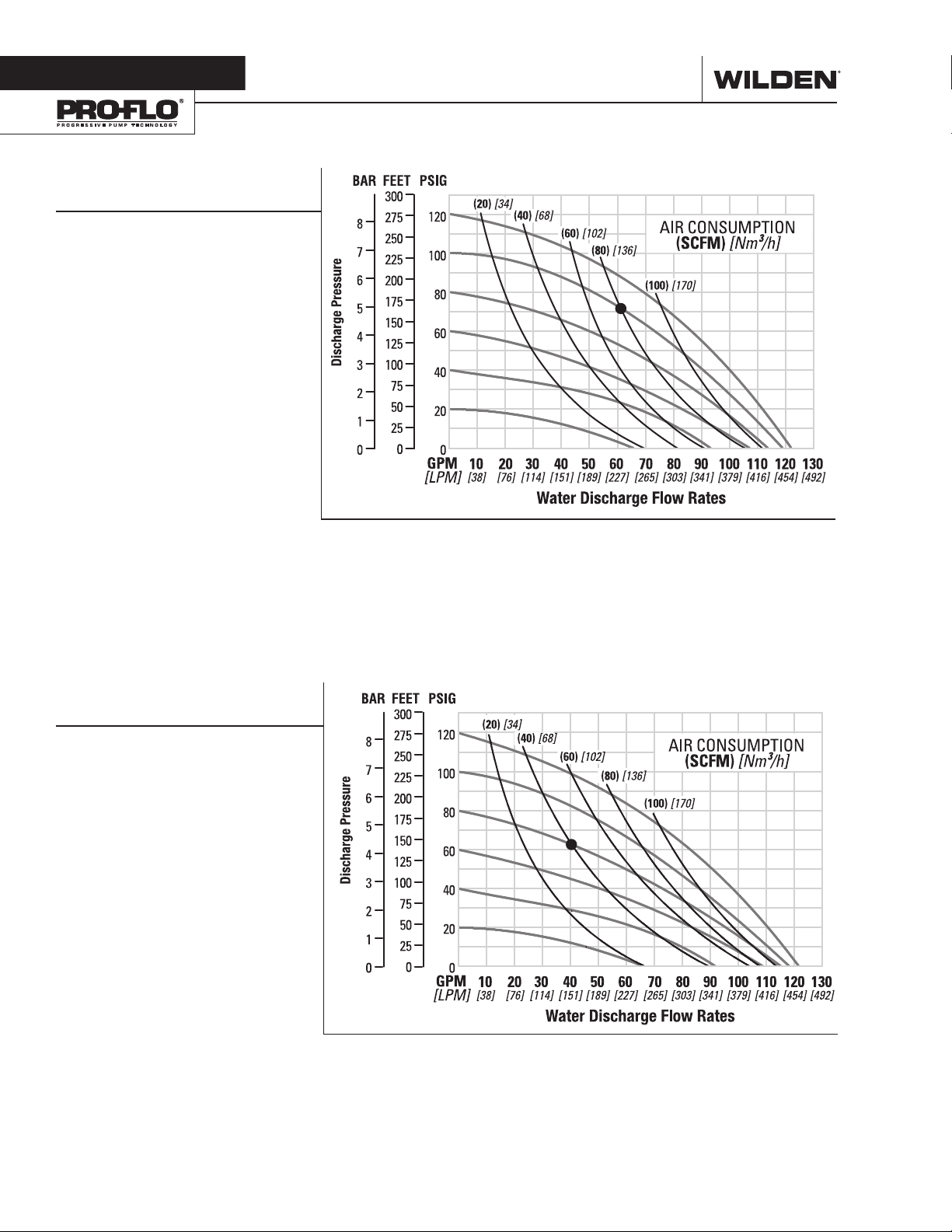
RUBBER-FITTED
Ship Weight .......Polypropylene 19 kg (41 lb)
PVDF 27 kg (59 lb)
Air Inlet ................................... 13 mm (1/2")
Inlet ...................................... 38 mm (1-1/2")
Outlet ................................... 38 mm (1-1/2")
Suction Lift ....................... 5.5 m Dry (18.2')
9.0 m Wet (29.5')
Disp. per Stroke1 .............. 1.25 L (0.330 gal)
Max. Flow Rate ............ 454 lpm (120 gpm)
Max. Size Solids ................... 6.4 mm (1/4")
1
Displacement per stroke was calculated at
4.8 bar (70 psig) air inlet pressure against a
2 bar (30 psig) head pressure.
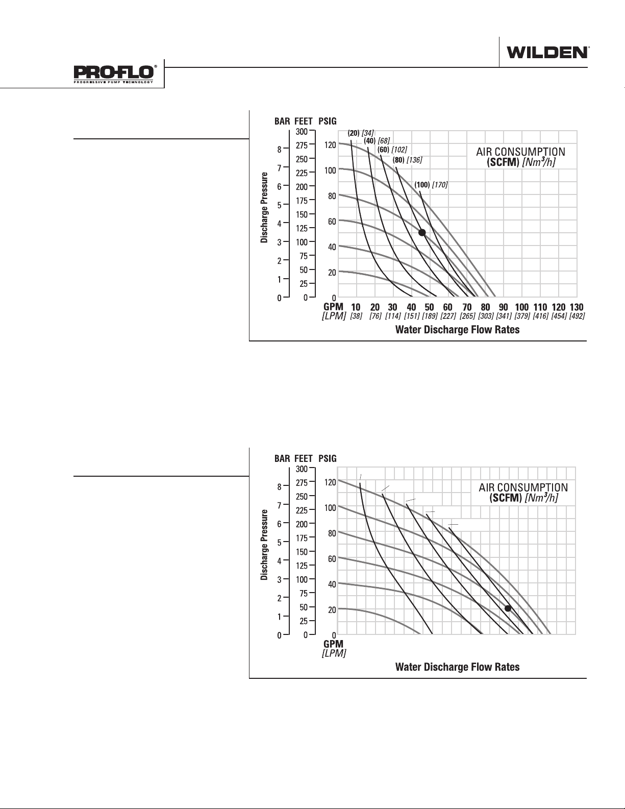
Example: To pump 227 lpm (60 gpm)
against a discharge head pressure of 5.0
bar (73 psig) requires 6.9 bar (100 psig)
and 136 Nm3/h (80 scfm) air consumption.
Caution: Do not exceed 8.6 bar (125 psig)
air supply pressure.
Flow rates indicated on chart were determined by pumping water.
For optimum life and performance, pumps should be specified so that daily operation
parameters will fall in the center of the pump's performance curve.
P400 PLASTIC
TPE-FITTED
Ship Weight .......Polypropylene 19 kg (41 lb)
PVDF 27 kg (59 lb)
Air Inlet ................................... 13 mm (1/2")
Inlet .............................. 38 mm (1-1/2")
Outlet ........................... 38 mm (1-1/2")
Suction Lift ....................... 4.8 m Dry (15.9')
9.3 m Wet (30.6')
Disp. per Stroke1 ............ 1.34 L (0.353 gal)
Max. Flow Rate ............ 454 lpm (120 gpm)
Max. Size Solids .................... 6.4 mm (1/4")
1
Displacement per stroke was calculated at
4.8 bar (70 psig) air inlet pressure against a
2 bar (30 psig) head pressure.
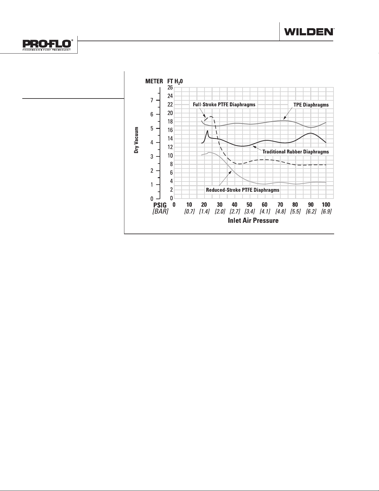
Example: To pump 151 lpm (40 gpm)
against a discharge head pressure of 4.3
bar (63 psig) requires 5.5 bar (80 psig) and
68 Nm3/h (40 scfm) air consumption.
Caution: Do not exceed 8.6 bar (125 psig)
air supply pressure.
Flow rates indicated on chart were determined by pumping water.
For optimum life and performance, pumps should be specified so that daily operation
parameters will fall in the center of the pump's performance curve.
WILDEN PUMP & ENGINEERING, LLC 6 WIL-11240-E-05
PERFORMANCE
P400 PLASTIC
REDUCED-STROKE PTFE-FITTED
Ship Weight .......Polypropylene 19 kg (41 lb)
PVDF 27 kg (59 lb)
Air Inlet ................................... 13 mm (1/2")
Inlet ...................................... 38 mm (1-1/2")
Outlet ................................... 38 mm (1-1/2")
Suction Lift ....................... 3.3 m Dry (10.8')
9.7 m Wet (31.8')
Disp. per Stroke
Max. Flow Rate .............. 318 lpm (84 gpm)
Max. Size Solids .................... 6.4 mm (1/4")
1
Displacement per stroke was calculated at
4.8 bar (70 psig) air inlet pressure against a
2 bar (30 psig) head pressure.
Example: To pump 178 lpm (47 gpm)
against a discharge head pressure of 3.4
bar (50 psig) requires 5.5 bar (80 psig) and
136 Nm3/h (80 scfm) air consumption.
Caution: Do not exceed 8.6 bar (125 psig)
air supply pressure.
1
............ 0.59 L (0.155 gal)
Flow rates indicated on chart were determined by pumping water.
For optimum life and performance, pumps should be specified so that daily operation
parameters will fall in the center of the pump's performance curve.
P400 PLASTIC
FULL-STROKE PTFE-FITTED
Ship Weight .... Polypropylene 19 kg (41 lb)
PVDF 27 kg (59 lb)
Air Inlet ................................... 13 mm (1/2”)
Inlet ......................................38 mm (1-1/2”)
Outlet ...................................38 mm (1-1/2”)
Suction Lift ............................5.7 Dry (18.7’)
9.3 m Wet (30.6’)
Disp. Per Stroke
Max. Flow Rate ...........424 lpm (111.9 gpm)
Max. Size Solids ....................6.4 mm (1/4”)
1
Displacement per stroke was calculated at
4.8 bar (70 psig) air inlet pressure against a
2.1 bar (30 psig)head pressure.
Example: To pump 337 lpm (89 gpm)
against a discharge head of 1.4 bar (20
psig) requires 5.5 bar (80 psig) and 147
Nm³/h (93 scfm) air consumption.
Caution: Do not exceed 8.6 bar (125 psig)
air supply pressure.
1
....................1.1 L (.30 gal)
20[34]
40[68]
60[102]
80[136]
100[170]
10 20 30 40 50 60 70 80 90 100 110 120
[38] [76] [114] [151] [189] [227] [265] [303] [341] [379] [416] [454]
Flow rates indicated on chart were determined by pumping water.
For optimum life and performance, pumps should be specified so that daily operation
parameters will fall in the center of the pump's performance curve.
WIL-11240-E-05 7 WILDEN PUMP & ENGINEERING, LLC
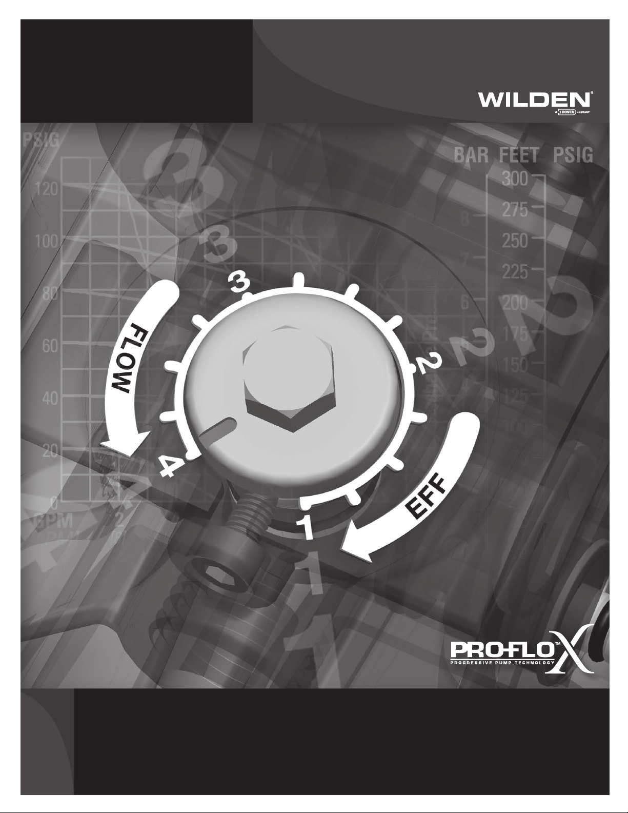
SUCTION-LIFT CURVES
P400 PLASTIC
SUCTION-LIFT
CAPABILITY
Suction-lift curves are calibrated for
pumps operating at 305 m (1,000')
above sea level. This chart is meant
to be a guide only. There are many
variables that can affect your
pump's operating characteristics.
The number of intake and discharge
elbows, viscosity of pumping fluid,
elevation (atmospheric pressure)
and pipe friction loss all affect the
amount of suction lift your pump will
attain.
WILDEN PUMP & ENGINEERING, LLC
8 WIL-11240-E-05
PX400
P L A S T I C
PX400 PERFORMANCE
Section 5B
Pro-Flo X
The Pro-Flo X™ air distribution system with the
revolutionary Efficiency Management System (EMS)
offers flexibility never before seen in the world of
AODD pumps. The
EMS is simple and
easy to use. With the
turn of an integrated
control dial, the
TM
Operating Principle
operator can select the optimal balance of flow and
efficiency that best meets the application needs.
Pro-Flo X™ provides higher performance, lower
operational costs
and flexibility that
exceeds previous
industry standards.
AIR CONSUMPTION
$
$
$
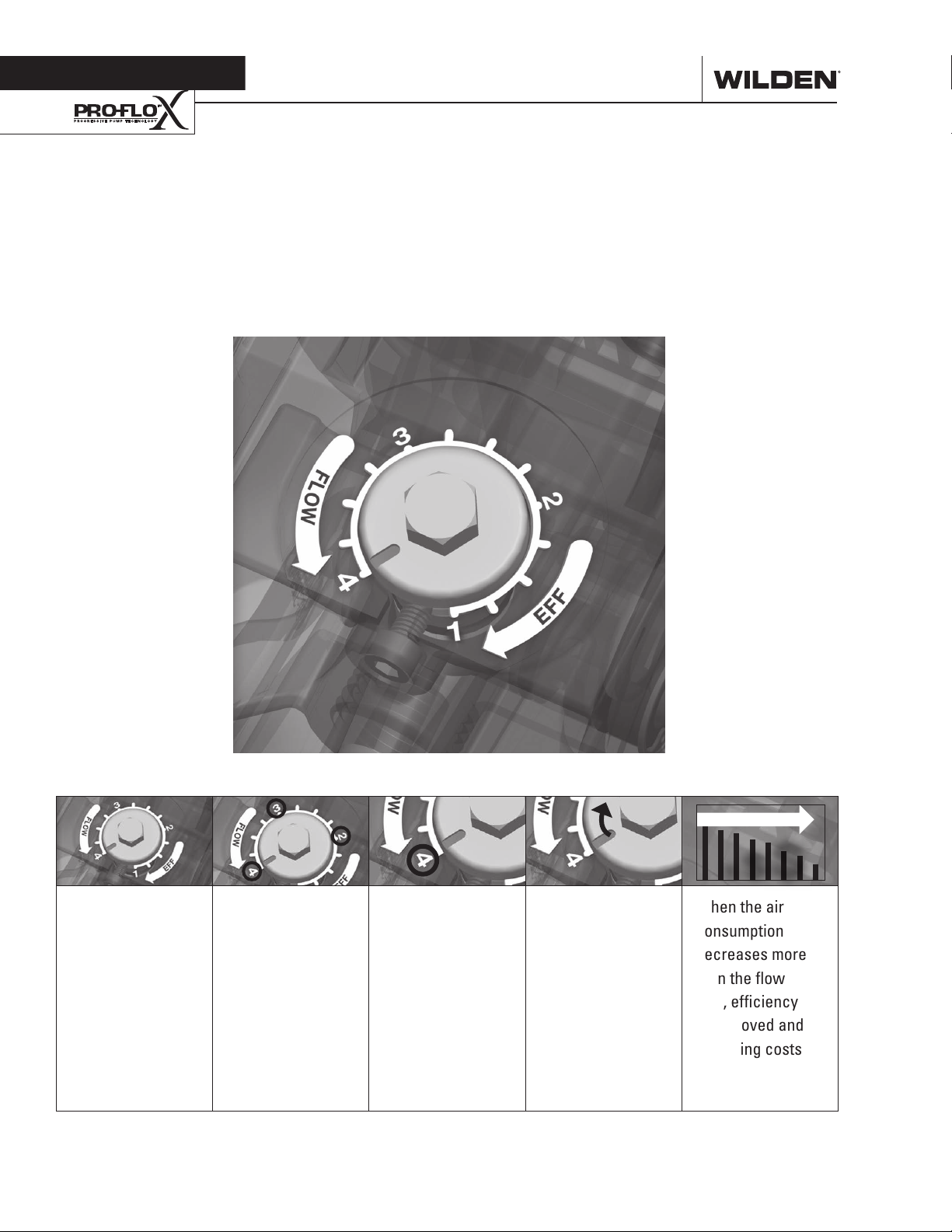
Turning the dial
changes the
relationship
between air inlet
and exhaust
porting.
WILDEN PUMP & ENGINEERING, LLC 10 PX400 Performance
Each dial setting
represents an
entirely different
flow curve.
Pro-Flo X™ pumps
are shipped from
the factory on
setting 4, which
is the highest
flow rate setting
possible.
Moving the dial
from setting 4
causes a decrease
in flow and an even
greater decrease in
air consumption.
When the air
consumption
decreases more
than the flow
rate, efficiency
is improved and
operating costs
are reduced.
 Loading...