

Wilden P4 Engineering, Operation & Maintenance
EOM
Engineering
Operation &
Maintenance
P4 Plastic Pump
Where Innovation Flows
wildenpump.com
TABLE OF CONTENTS
SECTION 1 CAUTIONS—READ FIRST! ..............................................1
SECTION 2 WILDEN PUMP DESIGNATION SYSTEM .................................2
SECTION 3 HOW IT WORKS—PUMP & AIR DISTRIBUTION SYSTEM ................3
SECTION 4 DIMENSIONAL DRAWING ..............................................4
SECTION 5 PERFORMANCE
P4 Plastic Rubber-Fitted ....................................................5
P4 Plastic TPE-Fitted .......................................................5
P4 Plastic Reduced-Stroke PTFE-Fitted ........................................6
P4 Plastic Full-Stroke PTFE-Fitted ............................................6
Suction-Lift Curves .......................................................7
SECTION 6 SUGGESTED INSTALLATION, OPERATION & TROUBLESHOOTING ........8
SECTION 7 DISASSEMBLY/REASSEMBLY ..........................................11
Air Valve / Center-Section Disassembly ......................................14
Reassembly Hints & Tips ..................................................16
PTFE Gasket Kit Installation ................................................17
SECTION 8 EXPLODED VIEW & PARTS LISTING
P4 Plastic Full-Stroke, 3-Piece Center-Section .................................18
P4 Plastic Reduced Stroke, 3-Piece Center-Section .............................20
SECTION 9 ELASTOMER OPTIONS .................................................24
Section 1
CAUTIONS—READ FIRST!
CAUTION: Do not apply compressed air to the
exhaust port — pump will not function.
CAUTION: Do not over lubricate air supply —
excess lubrication will reduce pump performance.
TEMPERATURE LIMITS:
Acetal –29°C to 82°C –20°F to 180°F
Buna-N –12°C to 82°C 10°F to 180°F
Geolast® –40°C to 82°C –40°F to 180°F
Neoprene –18°C to 93°C 0°F to 200°F
Nordel® EPDM –51°C to 138°C –60°F to 280°F
Nylon –18°C to 93°C 0°F to 200°F
PFA –7°C to 107°C 45°F to 225°F
Polypropylene 0°C to 79°C 32°F to 175°F
Polyurethane –12°C to 66°C 10°F to 150°F
PVDF –12°C to 107°C 10°F to 225°F
Saniflex™ –29°C to 104°C –20°F to 220°F
SIPD PTFE
SIPD PTFE
PTFE1 4°C to 104°C 40°F to 220°F
FKM –40°C to 177°C –40°F to 350°F
with
EPDM-backed 4°C to 137°C 40°F to 280°F
with
Neoprene-backed
4°C to 93°C 40°F to 200°F
Wil-Flex™ –40°C to 107°C –40°F to 225°F
1
4°C to 149°C (40°F to 300°F) - 13 mm (1/2") and 25 mm (1") models only.
NOTE: Not all materials are available for all
models. Refer to Section 2 for material options
for your pump.
WARNING: Prevent static sparking — If static
sparking occurs, fire or explosion could result.
Pump, valves, and containers must be grounded
when handling flammable fluids and whenever
discharge of static electricity is a hazard. To
ground the Wilden “Champ,” all clamp bands
must be grounded to a proper grounding point.
CAUTION: Do not exceed 8.6 bar (125 psig) air
supply pressure.
CAUTION: Before any maintenance or repair is
attempted, the compressed air line to the pump
should be disconnected and all air pressure
allowed to bleed from pump. Disconnect all
intake, discharge and air lines. Drain the pump by
turning it upside down and allowing any fluid to
flow into a suitable container.
CAUTION: Blow out air line for 10 to 20 seconds
before attaching to pump to make sure all
pipeline debris is clear. Use an in-line air filter. A
5µ (micron) air filter is recommended.
NOTE: When installing PTFE diaphragms, it is
important to tighten outer pistons simultaneously
(turning in opposite directions) to ensure tight fit.
CAUTION: When choosing pump materials, be
sure to check the temperature limits for all wetted
components. Example: FKM has a maximum
limit of 177°C (350°F) but polypropylene has a
maximum limit of only 79°C (175°F).
CAUTION: Maximum temperature limits are
based upon mechanical stress only. Certain
chemicals will significantly reduce maximum safe
operating temperatures. Consult engineering
guide for chemical compatibility and temperature
limits.
CAUTION: Always wear safety glasses when
operating pump. If diaphragm rupture occurs,
material being pumped may be forced out air
exhaust.
Plastic series pumps are made of virgin plastic
and are not UV-stabilized. Direct sunlight for
prolonged periods can cause deterioration of
plastics.
NOTE: P4 PVDF and PFA pumps come standard
from the factory with expanded PTFE gaskets
installed in the diaphragm bead of the liquid
chamber, in the T-section and in the ball and seat
area. PTFE gaskets cannot be re-used.
NOTE: Before starting disassembly, mark a line
from each liquid chamber to its corresponding air
chamber. This line will assist in proper alignment
during reassembly.
CAUTION: The P4 plastic pump is not submersible.
CAUTION: Pumps should be flushed thoroughly
with water before installation into process line.
CAUTION: Tighten all hardware prior to
installation.
WI L-10160 -E-10 1 WILDEN PUMP & ENGINEERING, LLC
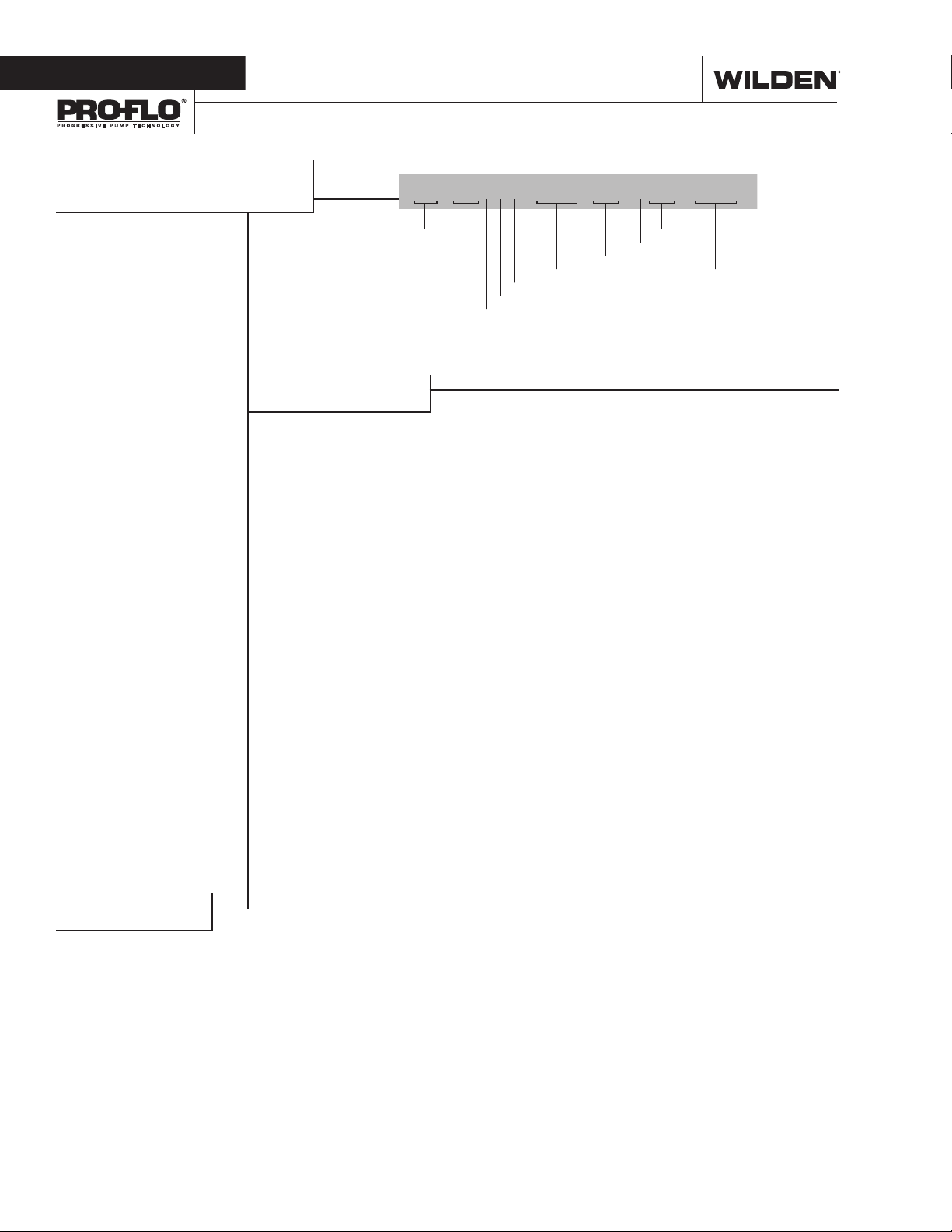
Section 2
WILDEN PUMP DESIGNATION SYSTEM
P4 PLASTIC
38 mm (1-1/2") Pump
Maximum Flow Rate:
352 lpm (93 gpm)
LEGEND
In the case where a center section is used instead of a center block , air chambers, and air valve,
P4 / XXX XX / XXX / XX / XXX / XXXX
MODEL
the designation w ill be as follows : Polypropylene = PPP, Acetal = L LL
MATERIAL CODES
WETTED PARTS & OUTER PISTON
KK = PVDF / PVDF
PP = POLYPROPYLENE /
POLYPROPYLENE
TT = PFA / PFA
AIR CHAMBER/CENTER SECTION
A = ALUMINUM
C = PTFE-COATED ALUMINUM
L = ACETAL
S = STAINLESS STEEL
V = HALAR®-COATED ALUMINUM
CENTER BLOCK / CENTER SECTION
L = ACETAL
P = POLYPROPYLENE
AIR VALVE
L = ACETAL
P = POLYPROPYLENE
DIAPHRAGMS
VALVE BALLS
AIR VALVE
CENTER BLOCK OR CENTER SECTION
AIR CHAMBERS OR CENTER SECTION
WETTED PARTS & OUTER PISTON
DIAPHRAGMS
BNS = BUNA-N (Red Dot)
BNU = BUNA-N, ULTRA-FLEX™
(Red Dot)
EPS = EPDM (Blue Dot)
EPU = EPDM, ULTRA-FLEX™
(Blue Dot)
FSS = SANIFLEX™
[Hytrel® (Cream)]
NES = NEOPRENE (Green Dot)
NEU = NEOPRENE, ULTRA-FLEX™
(Green Dot)
PUS = POLYURETHANE (Clear)
TEU = PTFE W/EPDM
BACKUP (White)
TSS = FULL-STROKE PTFE
W/SANIFLEX™ BACKUP
TSU = PTFE W/SANIFLEX™
BACKUP (White)
TWS = FULL-STROKE PTFE
W/WIL-FLEX™ BACKUP
VTS = FKM (White Dot)
VTU = FKM, ULTRA-FLEX™
WFS = WIL-FLEX™ [Santoprene®
(Three Black Dots)]
O-RINGS
VALVE SE ATS
VALVE BALLS
BN = BUNA-N (Red Dot)
EP = EPDM (Blue Dot)
FS = SANIFLEX™
FV = SANITARY FKM
(Two White Dots)
NE = NEOPRENE (Green Dot)
PU = POLYURETHANE (Brown)
TF = PTFE (White)
VT = FKM (White Dot)
WF = WIL-FLEX™ [Santoprene®
VALVE SEATS
K = PVDF
P = POLYPROPYLENE
T = PFA
VALVE SEAT O-RINGS
BN = BUNA-N
PU = POLYURETHANE (Brown)
TV = PTFE ENCAP. FKM
SPECIALT Y
CODE
(if applicable)
[Hytrel® (Cream)]
(Three Black Dots)]
SPECIALTY CODES
0100 Wil-Gard II™ 110V
0102 Wil-Gard II™ sensor wires ONLY
0103 Wil-Gard II™ 220V
0206 PFA-coated hardware,
Wil-Gard II™ sensor wires ONLY
0502 PFA-coated hardware
0504 DIN flange
0506 DIN flange, PFA-coated hardware
0512 Adapter block, no muffler,Pro-Flo®,
center section
NOTE: MOST E L AS TOMERIC MATERIAL S USE COLORED DOTS FOR IDENTIF ICATION.
WILDEN PUMP & ENGINEERING, LLC 2 W IL-1016 0 - E-10
0513 SS outer pistons
0560 Split manifold
0561 Split manifold, PFA-coated hardware
0563 Split manifold, discharge ONLY
0564 Split manifold, inlet ONLY
0603 PFA-coated hardware, Wil-Gard II™ 110V
0604 DIN flange, Wil-Gard II™ 220V
0606 DIN flange, PFA-coated hardware,
Wil-Gard II™ 220V
0608 PFA-coated hardware, Wil-Gard II™ 220V
0612 Ultrapure, PFA-coated hardware,
male connections
0618 Ultrapure, PFA-coated hardware,
Wil-Gard II™ 110V, male connections
0622 Ultrapure, male connections
0624 Ultrapure, Wil-Gard II™ 110V, male connections
0660 Split manifold, Wil-Gard II™ 110V
0661 Split manifold PFA-coated hardware,
Wil-Gard II™ 110V
OPEN
CLOSED
OPEN
CLOSED
OUTLET
INLET
BA
OUTLET
INLET
OPEN
CLOSED
CLOSED
OPEN
BA
MAIN SHAFT
CENTER BLOCK
PILOT
SPOOL
SMALL END
END CAP
LARGE END
AIR VALVE SPOOL
MUFFLER
MUFFLER PLATE
OUTLET
INLET
OPEN
CLOSED
CLOSED
OPEN
BA
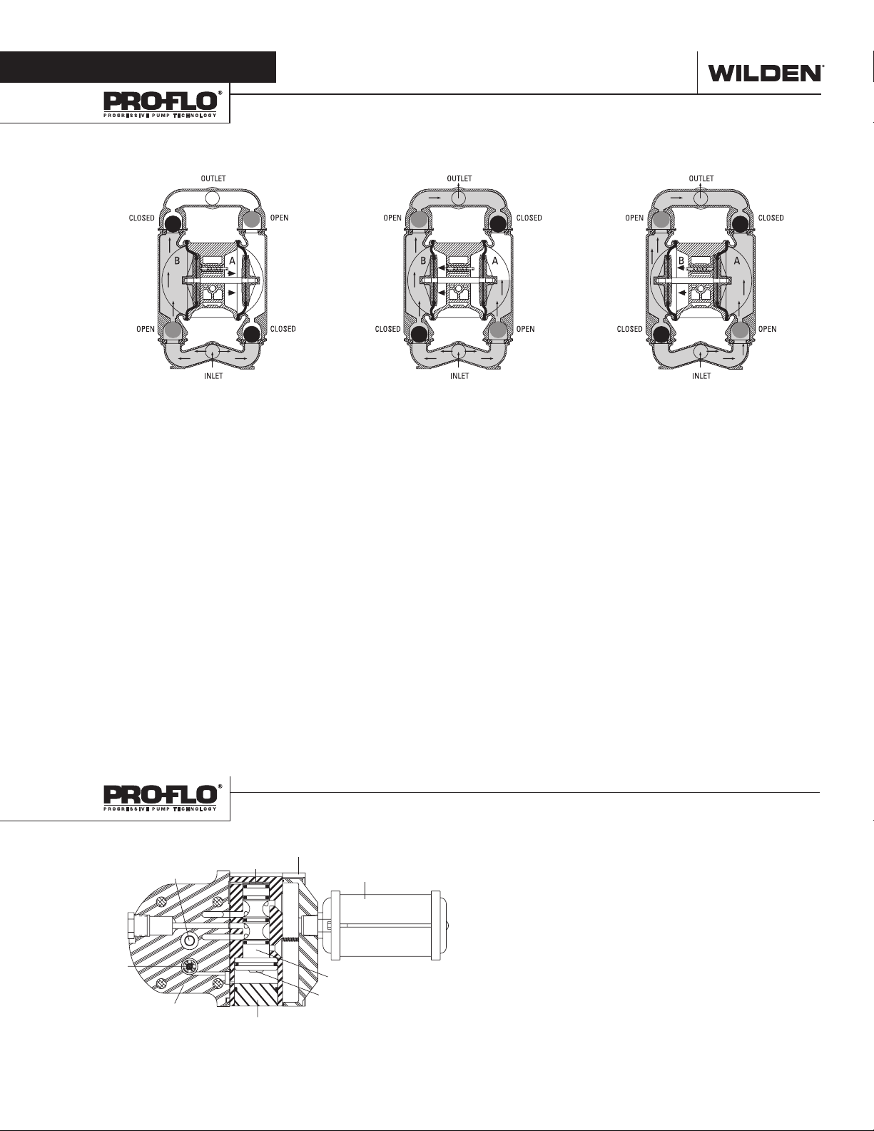
Section 3
HOW IT WORKS—PUMP
The Wilden diaphragm pump is an air-operated, positive displacement, self-priming pump. These drawings show flow pattern through
the pump upon its initial stroke. It is assumed the pump has no fluid in it prior to its initial stroke.
Right Stroke Mid Stroke Left Stroke
FIGURE 1 The air valve directs pressurized
air to the back side of diaphragm A. The
compressed air is applied directly to the
liquid column separated by elastomeric
diaphragms. The diaphragm acts as
a separation membrane between the
compressed air and liquid; a balanced
load removes mechanical stress from the
diaphragm. The compressed air moves
the diaphragm away from the center block
of the pump. The opposite diaphragm is
pulled in by the shaft connected to the
pressurized diaphragm. Diaphragm B is on
its suction stroke; air behind the diaphragm
has been forced out to the atmosphere
through the exhaust port of the pump.
The movement of diaphragm B toward the
center block of the pump creates a vacuum
within chamber B. Atmospheric pressure
forces fluid into the inlet manifold forcing
the inlet valve ball off its seat. Liquid is free
to move past the inlet valve ball and fill the
liquid chamber (see shaded area).
FIGURE 2 When the pressurized
diaphragm, diaphragm A, reaches the
limit of its discharge stroke, the air valve
redirects pressurized air to the back
side of diaphragm B. The pressurized air
forces diaphragm B away from the center
block while pulling diaphragm A to the
center block. Diaphragm B is now on its
discharge stroke. Diaphragm B forces the
inlet valve ball onto its seat due to the
hydraulic forces developed in the liquid
chamber and manifold of the pump. These
same hydraulic forces lift the discharge
valve ball off its seat, while the opposite
discharge valve ball is forced onto its seat,
forcing fluid to flow through the pump
discharge. The movement of diaphragm
A toward the center block of the pump
creates a vacuum within liquid chamber A.
Atmospheric pressure forces fluid into the
inlet manifold of the pump. The inlet valve
ball is forced off its seat allowing the fluid
being pumped to fill the liquid chamber.
FIGURE 3 At completion of the stroke, the
air valve again redirects air to the back side
of diaphragm A, which starts diaphragm
B on its exhaust stroke. As the pump
reaches its original starting point, each
diaphragm has gone through one exhaust
and one discharge stroke. This constitutes
one complete pumping cycle. The pump
may take several cycles to completely
prime depending on the conditions of the
application.
WI L-10160 - E-10 3 WILDEN PUMP & ENGINEERING, LLC
HOW IT WORKS—AIR DISTRIBUTION SYSTEM
Figure 1
The Pro-Flo® patented air distribution system incorporates
three moving parts: the air valve spool, the pilot spool, and
the main shaft/diaphragm assembly. The heart of the system
is the air valve spool and air valve. As shown in Figure 1, this
valve design incorporates an unbalanced spool. The smaller
end of the spool is pressurized continuously, while the large
end is alternately pressurized and exhausted to move the
spool. The spool directs pressurized air to one chamber
while exhausting the other. The air causes the main shaft/
diaphragm assembly to shift to one side — discharging liquid on
one side and pulling liquid in on the other side. When the shaft
reaches the end of its stroke, it actuates the pilot spool, which
pressurizes and exhausts the large end of the air valve spool. The
pump then changes direction and the same process occurs in the
opposite direction, thus reciprocating the pump.
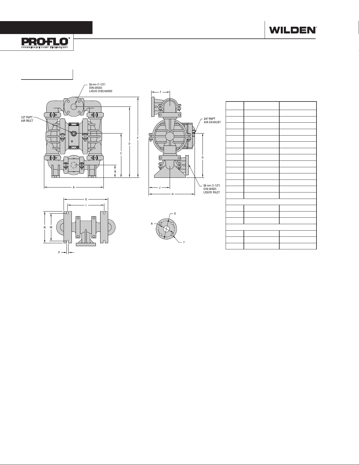
Section 4
P4 Plastic
DIMENSIONAL DRAWINGS
DIMENSIONS
ITEM METRIC (mm) STANDARD (inch)
A 394 15.5
B 79 3.1
C 287 11.3
D 465 18.3
E 528 20.8
F 122 4.8
G 287 11.3
H 300 11.8
J 137 5.4
K 287 11.3
L 236 9.3
M 180 7.1
N 203 8.0
P 10 0.4
DIN FLANGE
R 109 DIA. 4.3 DIA.
S 150 DIA. 5.9 DIA.
T 18 DIA. 0.7 DIA.
ANSI FLANGE
R 99 DIA. 3.9 DIA.
S 127 DIA. 5.0 DIA.
T 20 DIA. 0.8 DIA.
LW0496 REV. A
WILDEN PUMP & ENGINEERING, LLC 4 W IL-1016 0 - E-10
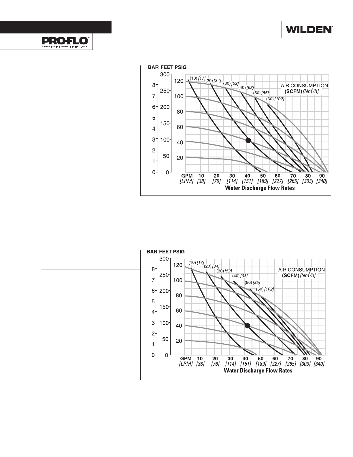
Section 5A
PERFORMANCE
P4 PLASTIC
RUBBER-FITTED
Ship Weight ...... Polypropylene 16.8 kg (37 lb)
Air Inlet ................................... 13 mm (1/2")
Inlet ...................................... 38 mm (1-1/2")
Outlet ................................... 38 mm (1-1/2")
Suction Lift ........................ 4.88 m Dry (16')
7.92 m Wet (26')
Disp. per Stroke1 .............. 1.19 L (0.314 gal)
Max. Flow Rate .............. 348 lpm (92 gpm)
Max. Size Solids .................. 4.8 mm (3/16")
1
Displacement per stroke was calculated at
4.8 bar (70 psig) air inlet pressure against a
2 bar (30 psig) head pressure.
Example: To pump 159 lpm (40 gpm)
against a discharge pressure head of 2.7
bar (40 psig) requires 4.1 bar (60 psig) and
30.6 Nm3/h (18 scfm) air consumption.
(See dot on chart.)
Caution: Do not exceed 8.6 bar (125 psig)
air supply pressure.
PVDF 21.3 kg (47 lb)
Flow rates indicated on chart were determined by pumping water.
For optimum life and performance, pumps should be specified so that daily operation
parameters will fall in the center of the pump's performance curve.
P4 PLASTIC
TPE-FITTED
Ship Weight ...... Polypropylene 16.8 kg (37 lb)
Air Inlet ................................... 13 mm (1/2")
Inlet ...................................... 38 mm (1-1/2")
Outlet ................................... 38 mm (1-1/2")
Suction Lift ........................ 3.96 m Dry (13')
7.92 m Wet (26')
Disp. per Stroke1 .............. 1.18 L (0.311 gal)
Max. Flow Rate .............. 354 lpm (94 gpm)
Max. Size Solids .................. 4.8 mm (3/16")
1
Displacement per stroke was calculated at
4.8 bar (70 psig) air inlet pressure against a
2 bar (30 psig) head pressure.
Example: To pump 42 gpm (159 lpm)
against a discharge pressure head of 2.7
bar (40 psig) requires 4.1 bar (60 psig) and
34 Nm3/h (20 scfm) air consumption. (See
dot on chart.)
Caution: Do not exceed 8.6 bar (125 psig)
air supply pressure.
PVDF 21.3 kg (47 lb)
Flow rates indicated on chart were determined by pumping water.
For optimum life and performance, pumps should be specified so that daily operation
parameters will fall in the center of the pump's performance curve.
WI L-10160 - E-10 5 WILDEN PUMP & ENGINEERING, LLC
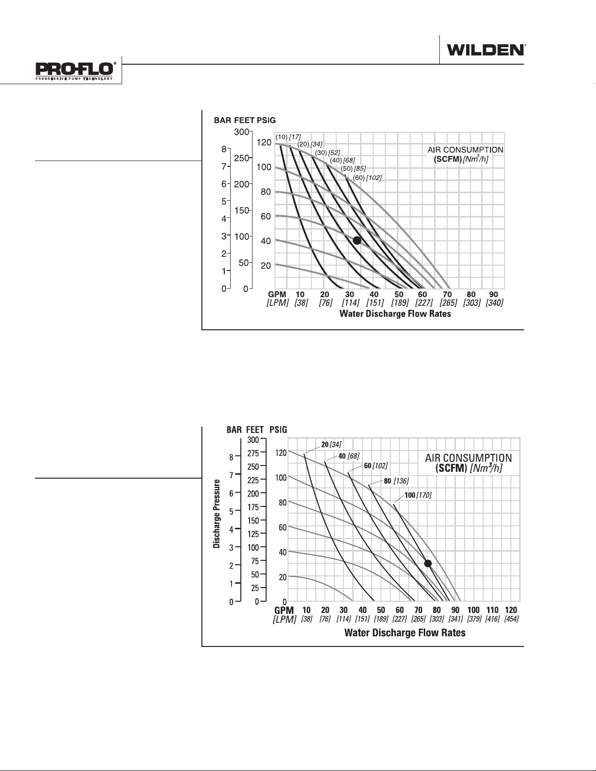
PERFORMANCE
P4 PLASTIC
REDUCED-STROKE
PTFE-FITTED
Ship Weight ...... Polypropylene 16.8 kg (37 lb)
PVDF 21.3 kg (47 lb)
PTFE PFA 23.9 kg (52 lb)
Air Inlet ................................... 13 mm (1/2")
Inlet ...................................... 38 mm (1-1/2")
Outlet ................................... 38 mm (1-1/2")
Suction Lift ................. 3.05 m Dry (10' Dry)
7.47 m Wet (24.5')
Disp. per Stroke1 ..............0.53 L (0.139 gal)
Max. Flow Rate .............. 261 lpm (69 gpm)
Max. Size Solids .................. 4.8 mm (3/16")
1
Displacement per stroke was calculated at
4.8 bar (70 psig) air inlet pressure against
a 2 bar (30 psig) head pressure.
Example: To pump 125 lpm (33 gpm)
against a discharge pressure head of 2.7
bar (40 psig) requires 4 bar (58 psig) and
45 Nm3/h (27 scfm) air consumption. (See
dot on chart.)
Caution: Do not exceed 8.6 bar (125 psig)
air supply pressure.
Flow rates indicated on chart were determined by pumping water.
For optimum life and performance, pumps should be specified so that daily operation
parameters will fall in the center of the pump's performance curve.
P4 PLASTIC
FULL-STROKE
PTFE-FITTED
Ship Weight ......
PVDF 21.3 kg (47 lb)
PTFE PFA 23.9 kg (52 lb)
Air Inlet ................................... 13 mm (1/2”)
Inlet ......................................38 mm (1-1/2”)
Outlet ...................................38 mm (1-1/2”)
Suction Lift ........................ 4.7m Dry (15.3’)
9.3 m Wet (30.6’)
Disp. per Stroke1 .................... 1.0 L (.27 gal)
Max. Flow Rate ........... 352 lpm (92.9 gpm)
Max. Size Solids ..................4.8 mm (3/16”)
1
Displacement per stroke was calculated at
4.8 bar (70 psig) air inlet pressure against
a 2.1 bar (30 psig) head pressure.
Example: To pump 288 lpm (76 gpm)
against a discharge head of 2.1 bar (30
psig) requires 6.9 bar (100 psig) and 158
Nm³/hr air consumption.
Caution: Do not exceed 8.6 bar (125 psig)
air supply pressure.
Polypropylene 16.8 kg (37 lb)
Flow rates indicated on chart were determined by pumping water.
For optimum life and performance, pumps should be specified so that daily operation
parameters will fall in the center of the pump's performance curve.
WILDEN PUMP & ENGINEERING, LLC 6 W IL-1016 0 - E-10
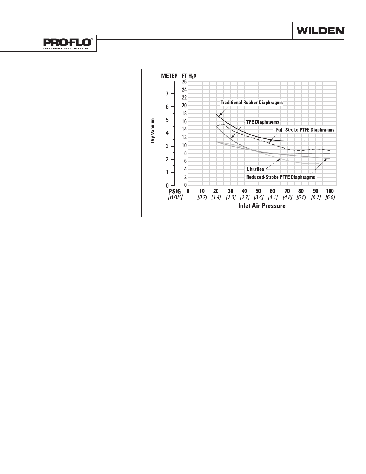
SUCTION-LIFT CURVES
P4 PLASTIC SUCTIONLIFT CAPABILITY
Suction-lift curves are calibrated for pumps operating
at 305 m (1,000') above sea level. This chart is meant
to be a guide only. There are many variables which can
affect your pump’s operating characteristics.
The number of intake and discharge elbows, viscosity
of pumping fluid, elevation (atmospheric pressure) and
pipe friction loss all affect the amount of suction lift
your pump will attain.
WI L-10160 - E-10 7 WILDEN PUMP & ENGINEERING, LLC
 Loading...