

Wilden P25 Series Manual
P25
Advanced™ Series PLASTIC Pumps
Advance your process
EOM
Engineering
Operation &
Maintenance
WIL-11020-E-0 3
REPLACES WIL-11020 -E- 02
TABLE OF CONTENTS
SECTION 1 CAUTIONS—READ FIRST! . . . . . . . . . . . . . . . . . . . . . . . . . . . . . . . . . . . . . . . . . . . . . .1
SECTION 2 WILDEN PUMP DESIGNATION SYSTEM . . . . . . . . . . . . . . . . . . . . . . . . . . . . . . . . .2
SECTION 3 HOW IT WORKS—PUMP & AIR DISTRIBUTION SYSTEM . . . . . . . . . . . . . . . .3
SECTION 4 DIMENSIONAL DRAWING . . . . . . . . . . . . . . . . . . . . . . . . . . . . . . . . . . . . . . . . . . . . . .4
SECTION 5 PERFORMANCE
A. Performance Curves
PTFE-Fitted . . . . . . . . . . . . . . . . . . . . . . . . . . . . . . . . . . . . . . . . . . . . . . . . . . . . . . . . . . 5
B. Suction Lift Curve . . . . . . . . . . . . . . . . . . . . . . . . . . . . . . . . . . . . . . . . . . . . . . . . . . . . . .5
SECTION 6 SUGGESTED INSTALLATION, OPERATION & TROUBLESHOOTING . . . . . . . . 6
SECTION 7 DISASSEMBLY / REASSEMBLY . . . . . . . . . . . . . . . . . . . . . . . . . . . . . . . . . . . . . . . . . 9
SECTION 8 EXPLODED VIEW & PARTS LISTING
PTFE-Fitted . . . . . . . . . . . . . . . . . . . . . . . . . . . . . . . . . . . . . . . . . . . . . . . . . . . . . . . . . . . . . 16
SECTION 9 ELASTOMER OPTIONS . . . . . . . . . . . . . . . . . . . . . . . . . . . . . . . . . . . . . . . . . . . . . . . . .18
Section 1
CAUTIONS—READ FIRST!
CAUTION: Do not apply compressed air to the
exhaust port — pump will not function.
CAUTION: Do not over-lubricate air supply —
excess lubrication will reduce pump performance.
Pump is pre-lubed.
TEMPERATURE LIMITS:
Polypropylene 0°C to 79.4°C 32°F to 175°F
PVDF –12.2°C to 107.2°C 10°F to 225°F
Neoprene –17.8°C to 93.3°C 0°F to 200°F
Buna-N –12.2°C to 82.2°C 10°F to 180°F
EPDM –51.1°C to 137.8°C –60°F to 280°F
Viton
Wil-Flex™ –40°C to 107.2°C –40°F to 225°F
Sanifl ex™ –28.9°C to 104.4°C –20°F to 220°F
Polyurethane –12.2°C to 65.6°C 10°F to 150°F
Tetra-Flex™ PTFE w/Neoprene Backed
4.4°C to 107.2°C 40°F to 225°F
Tetra-Flex™ PTFE w/EPDM Backed
-10°C to 137.8°C 14°F to 280°F
PTFE 4.4°C to 104.4°C 40°F to 220°F
®
–40°C to 176.7°C –40°F to 350°F
CAUTION: When choosing pump materials, be
sure to check the temperature limits for all wetted
components. Example: Viton® has a maximum
limit of 176.7°C (350°F) but polypropylene has a
maximum limit of only 79.4°C (175°F).
CAUTION: Maximum temperature limits are
based upon mechanical stress only. Certain
chemicals will signifi cantly reduce maximum
safe operating temperatures. Consult Chemical
Resistance Guide (E4) for chemical compatibility
and temperature limits.
WARNING: Prevention of static sparking — If
static sparking occurs, fi re or explosion could
result. Pump, valves, and containers must be
grounded to a proper grounding point when
handling fl ammable fl uids and whenever
discharge of static electricity is a hazard.
CAUTION: The process fl uid and cleaning fl uids
must be chemically compatible with all wetted
pump components (see E4).
CAUTION: Pumps should be thoroughly fl ushed
before installing into process lines. FDA and
USDA approved pumps should be cleaned and/
or sanitized before being used.
CAUTION: Always wear safety glasses when
operating pump. If diaphragm rupture occurs,
material being pumped may be forced out air
exhaust.
CAUTION: Before any maintenance or repair is
attempted, the compressed air line to the pump
should be disconnected and all air pressure
allowed to bleed from pump. Disconnect all
intake, discharge and air lines. Drain the pump
by turning it upside down and allowing any fl uid
to fl ow into a suitable container.
CAUTION: Blow out air line for 10 to 20 seconds
before attaching to pump to make sure all pipeline
debris is clear. Use an in-line air fi lter. A 5µ (micron)
air fi lter is recommended.
NOTE: Before starting disassembly, mark a line
from each liquid chamber to its corresponding air
chamber. This line will assis t in proper alignment
during reassembly.
CAUTION: Pro-Flo® pumps cannot be used in
submersible applications. Pro-Flo V™ is available
in both submersible and non-submersible
options. Do not use non-submersible Pro-Flo V™
models in submersible applications. Turbo-Flo™
pumps can be used in submersible applications.
CAUTION: Tighten all hardware prior to installation.
CAUTION: Do not exceed 8.6 bar (125 psig) air
supply pressure.
WIL-11020-E-03 1 WILDEN PUMP & ENGINEERING, LLC
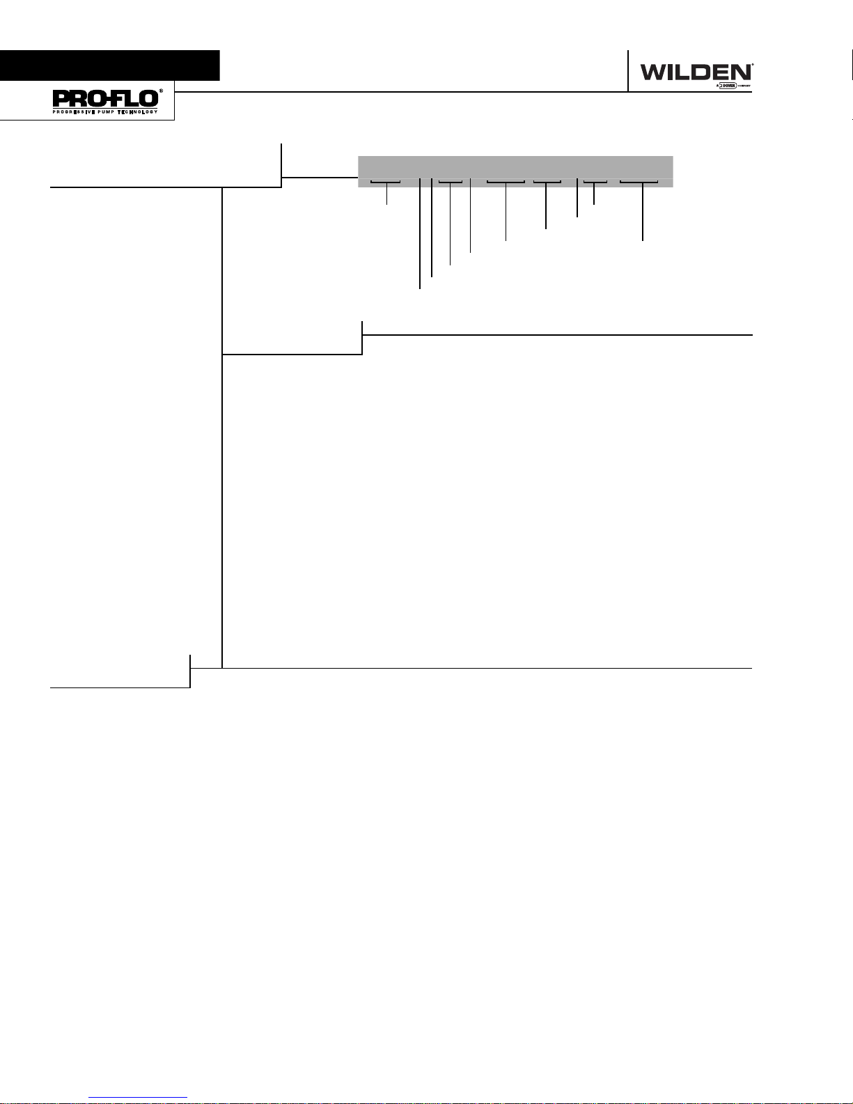
Section 2
WILDEN PUMP DESIGNATION SYSTEM
P25 PLASTIC
6 mm (1/4") Pump
Maximum Flow Rate:
16.7 lpm (4.4 gpm)
LEGEND
MATERIAL CODES
WETTED PARTS & OUTER PISTON
KZ = PVDF / NO PISTON
PZ = POLYPROPYLENE /
NO PISTON
CENTER BLOCK
PP = POLYPROPYLENE
AIR VALVE
P = POLYPROPYLENE
P25 / XXXX X / XXX / XX /XXX / XXXX
MODEL
VALVE BALLS
DIAPHRAGMS
AIR VALVE
CENTER SECTION
OUTER PISTON
WETTED PARTS
DIAPHRAGMS
TNL = PTFE W/NEOPRENE
BACK-UP O-RING, IPD
(White)
VALVE BALL
TF = PTFE (White)
O-RINGS
VALVE SEAT
VALVE SEAT
K = PVDF
P = POLYPROPYLENE
MANIFOLD O-RING
TV = PTFE ENCAP. VITON
SPECIALTY
CODE
(if applicable)
®
SPECIALTY CODES
0014 BPST
0502 PFA coated hardware
0670 Center ported, vertical inlet only, NPT
0671 Center ported, vertical inlet only, BPST
0672 Center ported, both ports vertical, NPT
0673 Center ported, both ports vertical, BPST
0677 Center ported, both ports horizontal, NPT
0678 Center ported, both ports horizontal, BPST
NOTE: MOST ELASTOMERIC MATERIALS USE COLORED DOTS FOR IDENTIFICATION
®
Viton
is a registered trademark of Dupont Dow Elastomers.
WILDEN PUMP & ENGINEERING, LLC 2 WIL-11020-E-03
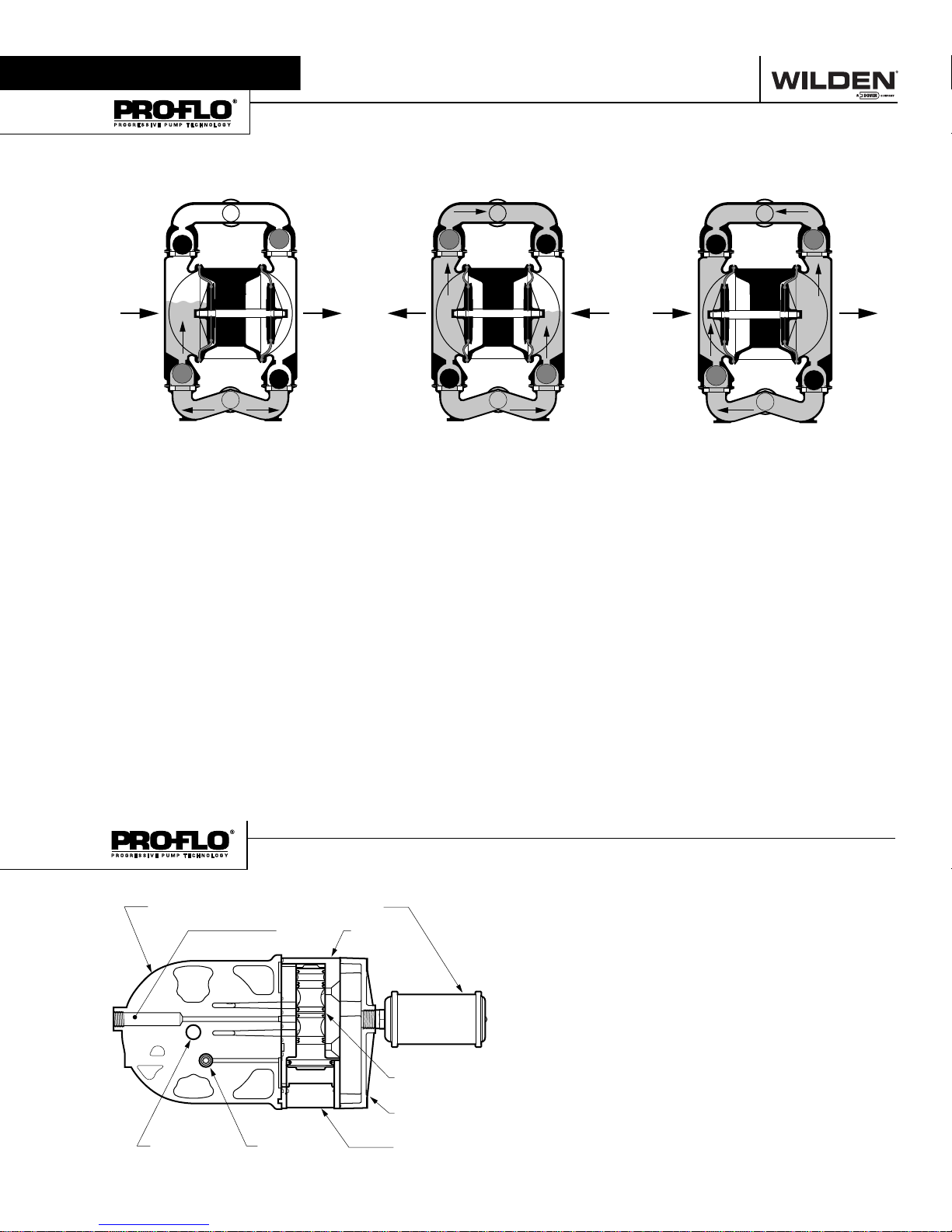
Section 3
HOW IT WORKS—PUMP
The Wilden diaphragm pump is an air-operated, positive displacement, self-priming pump. These drawings show fl ow pattern
through the pump upon its initial stroke. It is assumed the pump has no fl uid in it prior to its initial stroke.
#,/3%$
/54,%4
/0%.
"!
).,%4
FIGURE 1 The air valve dir ects pre ssurized
air to the back side of diaphragm A. The
compressed air is applied directly to the
liquid column separated by elastomeric
diaphragms. The diaphragm acts as
a separation membrane between the
compressed air and liquid, balancing the
load and removing mechanical stress
from the diaphragm. The compressed
air moves the diaphragm away from
the center of the pump. The opposite
diaphragm is pulled in by the shaft
connected to the pressurized diaphragm.
Diaphragm B is on its suction stroke; air
behind the diaphragm has been forced
out to atmosphere through the exhaust
port of the pump. The movement of
diaphragm B toward the center of the
pump creates a vacuum within chamber B.
Atmospheric pressure forces fl uid into
the inlet manifold forcing the inlet valve
ball off its seat. Liquid is free to move
past the inlet valve ball and fi ll the liquid
chamber (see shaded area).
#,/3%$/0%.
#,/3%$ /0%.
FIGURE 2 When the pressurized diaphragm,
diaphr agm A, re ache s the limit of i ts dis charge
stroke, the air valve redirects pressurized
air to the back side of diaphragm B. The
pressurized air forces diaphragm B away
from the center while pulling diaphragm A
to the center. Diaphragm B is now on its
discharge stroke. Diaphragm B forces the
inlet valve ball onto its seat due to the
hydraulic forces developed in the liquid
chamber and manifold of the pump. These
same hydraulic forces lift the discharge
valve ball off its seat, while the opposite
discharge valve ball is forced onto its seat,
forcing fl uid to fl ow through the pump
discharge. The movement of diaphragm A
toward the center of the pump creates a
vacuum within liquid chamber A. Atmospheric pressure forces fl uid into the inlet
manifold of the pump. The inlet valve ball
is forced off its seat allowing the fl uid being
pumped to fi ll the liquid chamber.
/0%.
"!
/54,%4
).,%4
#,/3%$
#,/3%$ /0%.
"!
/0%.
FIGURE 3 At completion of the stroke,
the air valve again redirec ts air to the
back side of diaphragm A, which star ts
diaphragm B on its exhaust stroke. As
the pump reaches its original starting
point, each diaphragm has gone through
one exhaust and one discharge stroke.
This constitutes one complete pumping
cycle. The pump may take several cycles
to completely prime depending on the
conditions of the application.
/54,%4
).,%4
#,/3%$
HOW IT WORKS—AIR DISTRIBUTION SYSTEM
!)2).,%4 !)26!,6%
-!).3(!&4
WIL-11020-E-03 3 WILDEN PUMP & ENGINEERING, LLC
0),/430//,
-5&&,%2#%.4%23%#4)/.
!)26!,6%30//,
-5&&,%20,!4%
%.$#!0
The Pro-Flo
moving parts: the air valve spool and the pilot spool. The hear t of
the system is the air valve spool and air valve. This valve design
incorporates an unbalanced spool. The smaller end of the spool
is pressurized continuously, while the large end is alternately
pressurized then exhausted to move the spool. The spool directs
pressurized air to one air chamber while exhausting the other.
The air causes the main shaft/diaphragm assembly to shif t to
one side — discharging liquid on that side and pulling liquid in
on the other side. When the shaft reaches the end of its stroke,
the inner piston actuates the pilot spool, which pressurizes and
exhausts the large end of the air valve spool. The repositioning
of the air valve spool routes the air to the other air chamber.
®
patented air distribution system incorporates two
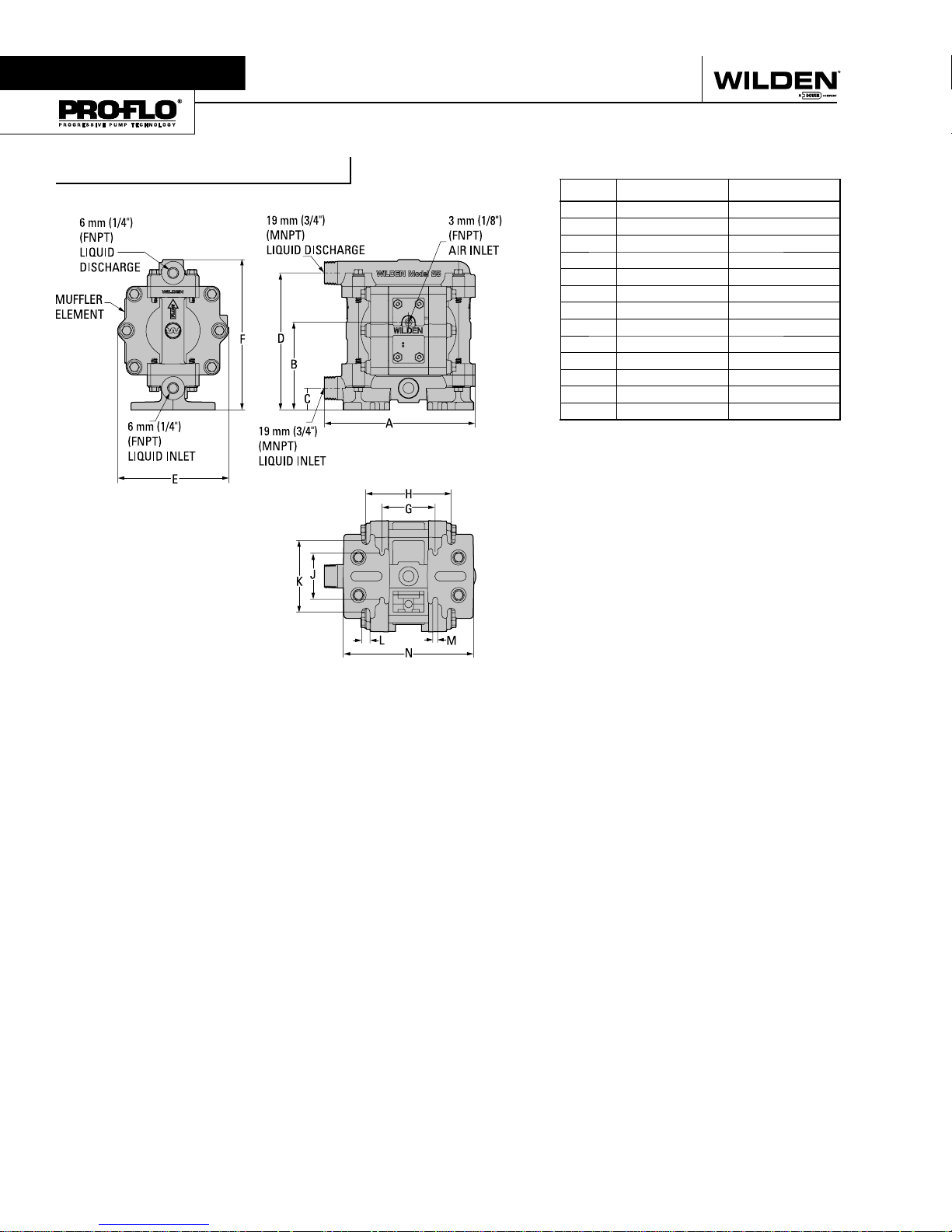
Section 4
DIMENSIONAL DRAWINGS
P25 Advanced™ Plastic
DIMENSIONS
ITEM METRIC (mm) STANDARD (inch)
A 173 6.8
B 102 4.0
C 25 1.0
D 157 6.2
E 127 5.0
F 173 6.8
G 61 2.4
H 99 3.9
J 53 2.1
K 81 3.2
L 10 0.4
M 5 0.2
N 150 5.9
WILDEN PUMP & ENGINEERING, LLC 4 WIL-11020-E-03
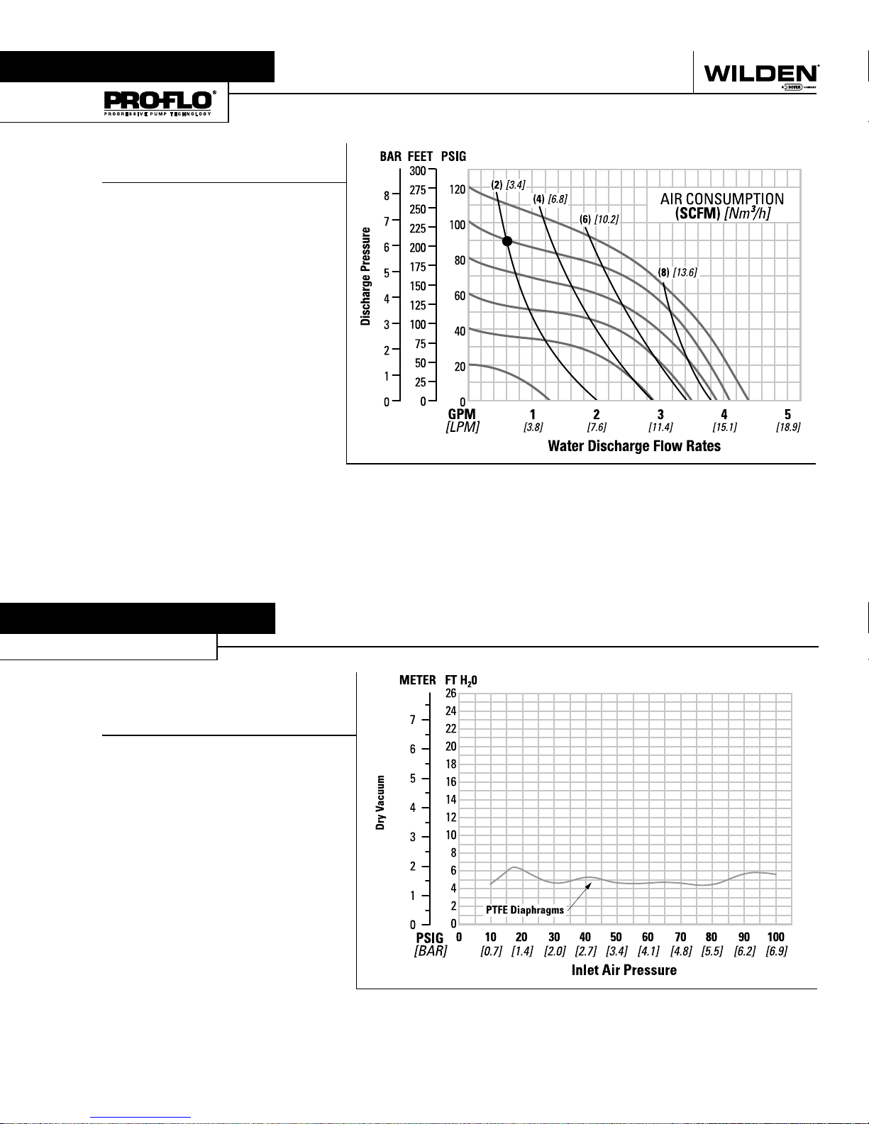
Section 5A
PERFORMANCE
P25 ADVANCED™ PLASTIC
PTFE-FITTED
Height ................................... 173 mm (6.8")
Width .................................... 173 mm (6.8")
Depth .................................... 127 mm (5.0")
Ship Weight ...... Polypropylene 2 kg (4 lbs)
PVDF 2 kg (5 lbs)
Air Inlet ..................................... 3 mm (1/8")
Inlet ........................................... 6 mm (1/4")
Outlet ........................................ 6 mm (1/4")
Suction Lift ..........................1.9 m Dry (6.2')
9.3 m Wet (30.6')
Displacement/Stroke ........0.04 l (0.01 gal.)
Max. Flow Rate ............ 16.7 lpm (4.4 gpm)
Max. Size Solids .................. 0.7 mm (1/32")
1
Displacement per stroke was calculated at
4.8 bar (70 psig) air inlet pressure against a
2 bar (30 psig) head pressure.
Example: To pump 2.3 lpm (0.6 gpm)
against a discharge pressure of 6.2 bar
(90 psig) requires 6.9 bar (100 psig) and
3.4 Nm3/h (2 scfm) air consumption. (See
dot on chart.)
Caution: Do not exceed 8.6 bar (125 psig)
air supply pressure.
1
Flow rates indicated on chart were determined by pumping water.
For optimum life and performance, pumps should be specifi ed so that daily operation
parameters will fall in the center of the pump performance curve.
Section 5B
SUCTION LIFT CURVE
P25 ADVANCED™
PLASTIC SUCTION
LIFT CAPABILITY
Suction lift curves are calibrated for pumps operating at 305 m
(1000') above sea level. This chart is meant to be a guide only.
There are many variables which can affect your pump’s operating
characteristics. The number of intake and discharge elbows,
viscosity of pumping fl uid, elevation (atmospheric pressure) and
pipe friction loss all affect the amount of suction lift your pump
will attain.
WIL-11020-E-03 5 WILDEN PUMP & ENGINEERING, LLC
 Loading...