

Wilden P100 Advanced PLASTIC Engineering, Operation & Maintenance
EOM
Engineering
Operation &
Maintenance
P100
Advanced™ Series
PLASTIC Pumps
Where Innovation Flows
www.wildenpump.com
WI L-1105 0-E
WIL-11050-E-05
REPLACES WIL-11050 -E- 04
TABLE OF CONTENTS
SECTION 1 CAUTIONS – READ FIRST! .............................................1
SECTION 2 PUMP DESIGNATION SYSTEM .........................................2
SECTION 3 HOW IT WORKS (PUMP & AIR SYSTEMS) ..............................3
SECTION 4 DIMENSIONAL DRAWING
A. P100 ADVANCED™ PLASTIC .............................................4
B. P100 ADVANCED™ PLASTIC - Center Ported ................................5
C. P100 ADVANCED™ PLASTIC - Vertical Ported ................................6
SECTION 5 PERFORMANCE CURVES
A. P100 ADVANCED™ PLASTIC Rubber-Fitted .................................7
B. P100 ADVANCED™ PLASTIC TPE-Fitted ....................................7
C. P100 ADVANCED™ PLASTIC PTFE-Fitted ...................................8
SECTION 6 SUCTION LIFT CURVES & DATA .........................................8
SECTION 7 INSTALLATION AND OPERATION
A. Installation ............................................................9
B. Operation & Maintenance ...............................................10
C. Troubleshooting .......................................................11
SECTION 8 DIRECTIONS FOR DISASSEMBLY/REASSEMBLY
A. P100 ADVANCED™ PLASTIC Wetted – Tools Required, Cautions ...............12
B. Pro-Flo® Air Valve/Center Block – Disassembly, Cleaning, Inspection ............15
C. Reassembly Hints & Tips, Torque Specifications ............................17
SECTION 9 EXPLODED VIEW/PARTS LISTING
A. P100 ADVANCED™ PLASTIC PTFE/PTFE-IPD-Fitted ..........................18
SECTION 10 ELASTOMER OPTIONS ................................................20
Section 1
CAUTIONS — READ FIRST!
TEMPERATURE LIMITS*
Wetted Path
Polypropylene (PP) 0°C to 79.4°C 32°F to 175°F
Polyvinylidene fluoride (PVDF)
-12.2°C to 107.2°C 10°F to 225°F
Elastomers
Neoprene -17.8°C to 93.3°C 0°F to 200°F
Buna-N -12.2°C to 82.2°C 10°F to 180°F
Viton
Wil-Flex™ -40°C to 107.2°C -40°F to 225°F
Polyurethane 12.2°C to 65.6°C 10°F to 150°F
Polytetrafluoroethylene (PTFE)
4.4°C to 104.4°C 40°F to 220°F
Saniflex™ -28.9°C to 104.4°C -20°F to 220°F
*Elastomer choice may change temperature limits
CAUTION: When choosing pump materials, be sure
to check the temperature limits for all wetted components. Example: Viton
(350°F) but polypropylene has a maximum limit of only
79.4°C (175°F).
CAUTION: Maximum temperature limits are based
upon mechanical stress only. Certain chemicals will
significantly reduce maximum safe operating temperatures. Consult engineering guide for chemical compatibility and temperature limits.
CAUTION: Always wear safety glasses when operat-
ing pump. If diaphragm rupture occurs, material being
pumped may be forced out air exhaust.
WARNING: Prevention of static sparking — If static
sparking occurs, fire or explosion could result. Proper
grounding of pump, valves, and containers is critical
when handling flammable fluids or whenever discharge
of static electricity is a hazard.
CAUTION: Do not exceed 8.6 bar (125 psig) air supply
pressure.
CAUTION: Advanced™ series plastic pumps are made
with plastic that is not UV stabilized. Direct sunlight for
prolonged periods can cause deterioration of plastics.
®
-40°C to 176.7°C -40°F to 350°F
®
has a maximum limit of 176.7°C
CAUTION: Before any maintenance or repair is
attempted, the compressed air line to the pump should
be disconnected and all air pressure allowed to bleed
from pump. Disconnect all intake, discharge and air
lines. Drain the pump by turning it upside down and
allowing any fluid to flow into a suitable container.
CAUTION: Blow out air line for 10 to 20 seconds before
attaching to pump to make sure all pipe line debris is
clear. Use an in-line air filter. A 5µ (micron) air filter is
recommended.
NOTE: Tighten all bolts prior to installation. Fasteners
may loosen during transportation. See torque specifications on page 15.
NOTE: When installing polytetrafluoroethylene (PTFE) dia-
phragms, it is important to tighten outer pistons simultaneously (turning in opposite directions) to ensure tight fit.
CAUTION: Verify the chemical compatibility of the
process and cleaning fluid to the pump’s component
materials in the Chemical Resistance Guide (see E4).
CAUTION: When removing the end cap using compressed
air, the air valve end cap may come out with considerable
force. Hand protection such as a padded glove or rag
should be used to capture the end cap.
CAUTION: Do not over-tighten the air inlet reducer
bushing. Additionally, too much torque on the muffler
may damage the air valve muffler plate.
WIL-11050-E-05 1 WILDEN PUMP & ENGINEERING, LLC
Section 2
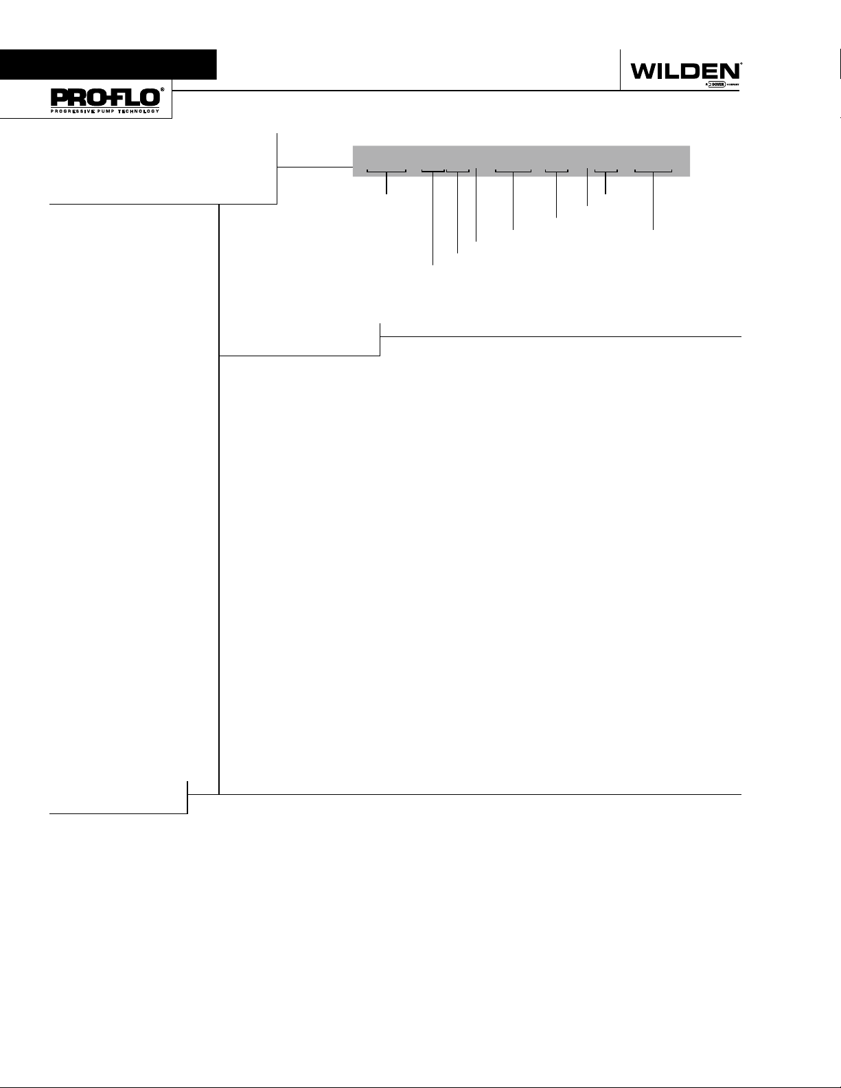
THE WILDEN PUMP DESIGNATION SYSTEM
P100 ADVANCED™
PLASTIC
13 mm (1/2") Pump
Maximum Flow Rate:
58.7 LPM (15.5 GPM)
MATERIAL CODES
WETTED PARTS & OUTER PISTON
KK = PVDF / PVDF
PP = POLYPROPYLENE /
CENTER SECTION
PP = POLYPROPYLENE
AIR VALVE
P = POLYPROPYLENE
LEGEND
POLYPROPYLENE
P100 / X XX XX / XXX / XX / XXX / XXXX
MODEL
VALVE BALLS
DIAPHRAGMS
AIR VALVE
CENTER SECTION
WETTED PARTS & OUTER PISTON
DIAPHRAGMS
BNS = BUNA-N (Red Dot)
FSS = SANIFLEX™
[Hytrel® (Cream)]
PUS = POLYURETHANE (Clear)
THU = PTFE W/HI-TEMP
BUNA-N BACK-UP (White)
TNL = PTFE W/NEOPRENE
BACK-UP, IPD (White)
TNU = PTFE W/NEOPRENE
BACK-UP (White)
VTS = VITON® (White Dot)
WFS = WIL-FLEX™ [Santoprene®
(Three Black Dots)]
O-RINGS
VALVE SEAT
VALVE BALL
BN = BUNA-N (Red Dot)
FS =
SANIFLEX ™
[Hytrel® (Cream)]
PU = POLYURETHA NE (Brown)
TF = PTFE (White )
VT = VI TON® (White Dot)
WF = W IL-FLE X™ [Santoprene®
(Three Black Dots )]
VALVE SEAT
K = PVDF
P = POLYPROPYLENE
VALVE SEAT O-RING
BN = BUNA-N
PU = POLYURETHANE (Brown)
TV = PTFE ENCAP. VITON®
WF = WIL-FLEX™ (Santoprene®)
VT = FKM
SPECIALTY
CODE
(if applicable)
SPECIALTY CODES
0014 BSPT
0102 Wil-Gard II™, sensor wires ONLY
0677 Center ported, NPT (Parts Only)
0678 Center ported, BSPT (Parts Only)
0680 P100 with OEM specific inlet manifold
0683 P100 with OEM specific inlet manifold, center
ported inlet and discharge manifolds, NPT
0790 P100 Advanced, drum pump inlet manifold
NOTES: MOST EL ASTOMERIC MATERIALS USE COLORED DOTS FOR IDEN TIFICATION.
Viton® is a registered trademark of DuPont Dow Elastomers.
WILDEN PUMP & ENGINEERING, LLC 2 WIL-11050-E-05
Section 3
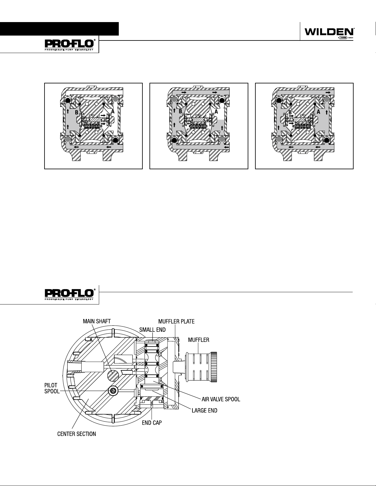
THE WILDEN PUMP – HOW IT WORKS
The Wilden diaphragm pump is an air-operated, positive displacement, self-priming pump. These drawings show the flow
pattern through the pump upon its initial stroke. It is assumed the pump has no fluid in it prior to its initial stroke.
OUTLET
CLOSED CLOSED OPENOPEN
OPEN OPEN CLOSED
INLET
RIGHT STROKE
FIGURE 1 The air valve directs pressurized air to
the back side of diaphragm A. The compressed
air is applied directly to the liquid column separated by elastomeric diaphragms. The diaphragm
acts as a separation membrane between the
compressed air and liquid, balancing the load and
removing mechanical stress from the diaphragm.
The compressed air moves the diaphragm away
from the center section of the pump. The opposite
diaphragm is pulled in by the shaft connected to
the pressurized diaphragm. Diaphragm B is on its
suction stroke; air behind the diaphragm has been
forced out to the atmosphere through the exhaust
port of the pump. The movement of diaphragm B
toward the center section of the pump creates a
vacuum within chamber B. Atmospheric pressure
forces fluid into the inlet manifold forcing the inlet
valve ball off its seat. Liquid is free to move past
the inlet valve ball and fill the liquid chamber (see
shaded area).
OPEN
CLOSEDCLOSED
LEFT STROKE RIGHT STROKE
FIGURE 2 When the pressurized diaphragm,
diaphragm A, reaches the limit of its discharge
stroke, the air valve redirects pressurized air to
the back side of diaphragm B. The pressurized air
forces diaphragm B away from the center section
while pulling diaphragm A to the center section.
Diaphragm B is now on its discharge stroke.
Diaphragm B forces the inlet valve ball onto its
seat due to the hydraulic forces developed in the
liquid chamber and manifold of the pump. These
same hydraulic forces lift the discharge valve ball
off its seat, while the opposite discharge valve ball
is forced onto its seat, forcing fluid to flow through
the pump discharge. The movement of diaphragm
A toward the center section of the pump creates
a vacuum within liquid chamber A. Atmospheric
pressure forces fluid into the inlet manifold of the
pump. The inlet valve ball is forced off its seat
allowing the fluid being pumped to fill the liquid
chamber.
OUTLET
CLOSED
OPEN
INLET
FIGURE 3 At completion of the stroke, the air valve
again redirects air to the back side of diaphragm A,
which starts diaphragm B on its exhaust stroke. As
the pump reaches its original starting point, each
diaphragm has gone through one exhaust and one
discharge stroke. This constitutes one complete
pumping cycle. The pump may take several cycles
to completely prime depending on the conditions
of the application.
OUTLET
INLET
HOW IT WORKS—AIR DISTRIBUTION SYSTEM
The Pro-Flo® patented air distribution system
incorporates three moving parts: the air valve
spool, the pilot spool, and the main shaft/diaphragm assembly. The heart of the system is
the air valve spool and air valve. This valve
design incorporates an unbalanced spool. The
smaller end of the spool is pressurized continuously, while the large end is alternately pressurized then exhausted to move the spool. The
spool directs pressurized air to one air chamber
while exhausting the other. The air causes the
main shaft/diaphragm assembly to shift to one
side — discharging liquid on that side and pulling liquid in on the other side. When the shaft
reaches the end of its stroke, the inner piston
actuates the pilot spool, which pressurizes and
exhausts the large end of the air valve spool.
The repositioning of the air valve spool routes
the air to the other air chamber.
WIL-11050-E-05 3 WILDEN PUMP & ENGINEERING, LLC
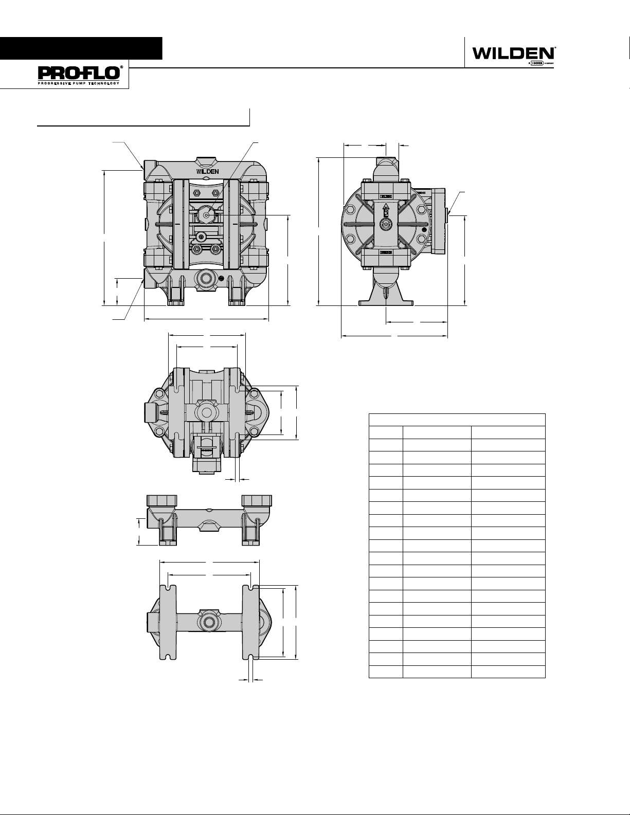
Section 4A
DIMENSIONAL DRAWING
P100 Advanced™ Plastic
1/2" BSPT (FNPT)
LIQUID DISCHARGE
D
1/2" BSPT (FNPT)
LIQUID INLET
1/4" FNPT
AIR INLET
E
C
B
A
L
M
P
N
G
F
1/2" FNPT
AIR EXHAUST
K
H
J
DIMENSIONS – P100 ADVANCED™ PLASTIC
ITEM METRIC (mm) STANDARD (inch)
A 234 9.2
B 51 2.0
C 170 6.7
R
D 254 10.0
E 279 11.0
F 81 3.2
G 25 1.0
B
H 114 4.5
J 201 7.9
S
T
K 170 6.7
L 145 5.7
M 114 4.5
N 81 3.6
P 102 4.0
V
U
R 8 0.3
S 188 7.4
T 155 6.1
U 130 5.1
R
V 140 5.5
LW0347 REV B
ALTERNATE FOOTPRINT
WILDEN PUMP & ENGINEERING, LLC 4 WIL-11050-E-05
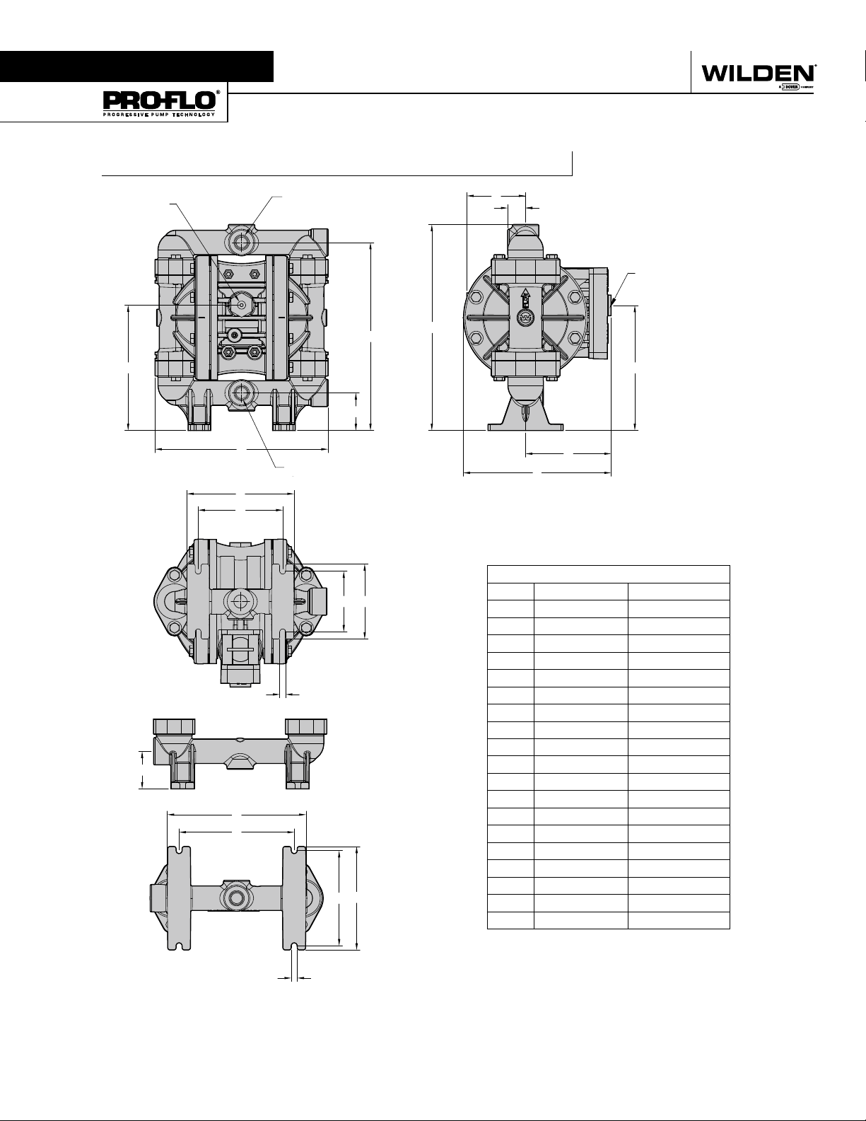
Section 4B
DIMENSIONAL DRAWING
P100 Advanced™ Plastic - Center Ported
1/4" FNPT
AIR INLET
C
B
1/2" BSPT (FNPT
LIQUID DISCHARGE
A
1/2" BSPT (FNPT)
LIQUID INLET
L
M
)
D
B
E
F
G
1/2" FNPT
AIR EXHAUST
K
H
J
DIMENSIONS – P100 ADVANCED™ CENTER PORTED PLASTIC
N P
ITEM METRIC (mm) STANDARD (inch)
A 234 9.2
B 51 2.0
C 170 6.7
D 254 10.0
E 279 11.0
R
F 81 3.2
G 25 1.0
H 114 4.5
J 201 7.9
K 170 6.7
L 145 5.7
M 114 4.5
S
T
N 81 3.6
P 102 4.0
R 8 0.3
S 188 7.4
V
U
T 155 6.1
U 130 5.1
V 140 5.5
LW0472 REV A
R
ALTERNATE FOOTPRINT
WIL-11050-E-05 5 WILDEN PUMP & ENGINEERING, LLC
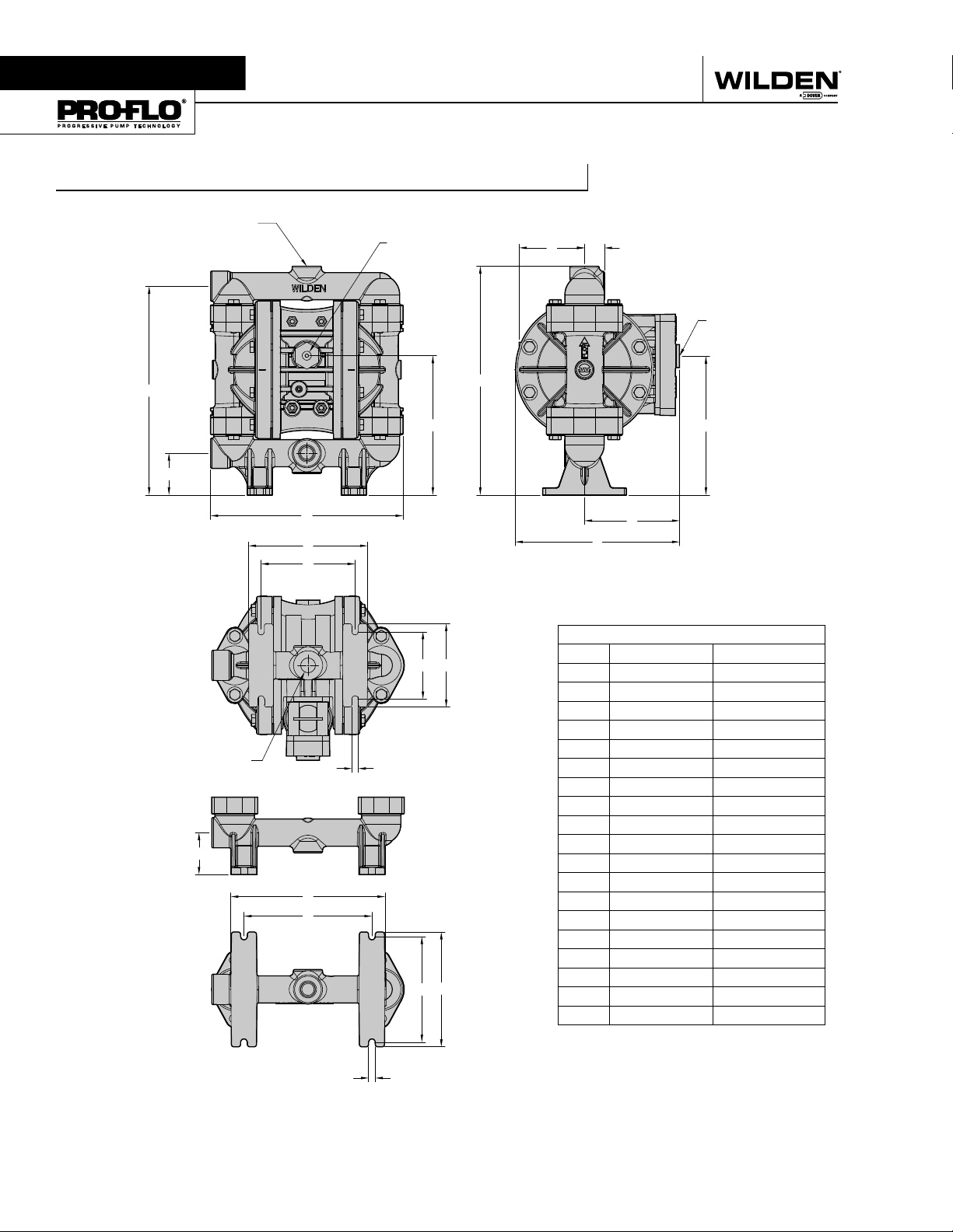
Section 4C
DIMENSIONAL DRAWING
P100 Advanced™ Plastic - Vertical Ported
1/2" BSPT (FNPT)
LIQUID DISCHARGE
1/4" FNPT
AIR INLET
F
G
1/2" FNPT
AIR EXHAUST
D
B
1/2" BSPT (FNPT)
LIQUID INLET
E
C
A
L
M
H
J
K
DIMENSIONS – P100 ADVANCED™ VERTICAL PORTED PLASTIC
N
P
ITEM METRIC (mm) STANDARD (inch)
A 234 9.2
B 51 2.0
C 170 6.7
D 254 10.0
E 279 11.0
R
F 81 3.2
G 25 1.0
H 114 4.5
J 201 7.9
B
K 170 6.7
L 145 5.7
M 114 4.5
S
T
N 81 3.6
P 102 4.0
R 8 0.3
S 188 7.4
U V
T 155 6.1
U 130 5.1
V 140 5.5
LW0473 REV A
P
WILDEN PUMP & ENGINEERING, LLC 6 WIL-11050-E-05
 Loading...