

Wilden P1, PX1 Engineering, Operation & Maintenance
P1/PX1
Original™ Series METAL Pumps
Simplify your process
Engineering
Operation &
Maintenance
LISTED
79
WIL-103 00 -E -10
REPLACES WIL-10300- E-09
TABLE OF CONTENTS
SECTION 1 CAUTIONS—READ FIRST! . . . . . . . . . . . . . . . . . . . . . . . . . . . . . . . . . . . . . . . . . . . . . .1
SECTION 2 WILDEN PUMP DESIGNATION SYSTEM . . . . . . . . . . . . . . . . . . . . . . . . . . . . . . . . . 2
SECTION 3 HOW IT WORKS—PUMP & AIR DISTRIBUTION SYSTEM . . . . . . . . . . . . . . . . 3
SECTION 4 DIMENSIONAL DRAWINGS . . . . . . . . . . . . . . . . . . . . . . . . . . . . . . . . . . . . . . . . . . . . .4
SECTION 5 PERFORMANCE
A. P1 Performance Curves
Rubber-Fitted . . . . . . . . . . . . . . . . . . . . . . . . . . . . . . . . . . . . . . . . . . . . . . . . . . . . . . . .6
TPE-Fitted . . . . . . . . . . . . . . . . . . . . . . . . . . . . . . . . . . . . . . . . . . . . . . . . . . . . . . . . . . .6
PTFE-Fitted . . . . . . . . . . . . . . . . . . . . . . . . . . . . . . . . . . . . . . . . . . . . . . . . . . . . . . . . . . 7
B. PX1 Performance
Operating Principal . . . . . . . . . . . . . . . . . . . . . . . . . . . . . . . . . . . . . . . . . . . . . . . . . . 10
How to Use this EMS Curve . . . . . . . . . . . . . . . . . . . . . . . . . . . . . . . . . . . . . . . . . . . 11
Performance Curves
Rubber-Fitted . . . . . . . . . . . . . . . . . . . . . . . . . . . . . . . . . . . . . . . . . . . . . . . . . . . . 14
TPE-Fitted . . . . . . . . . . . . . . . . . . . . . . . . . . . . . . . . . . . . . . . . . . . . . . . . . . . . . . .15
PTFE-Fitted . . . . . . . . . . . . . . . . . . . . . . . . . . . . . . . . . . . . . . . . . . . . . . . . . . . . . .16
C. Suction Lift Curves . . . . . . . . . . . . . . . . . . . . . . . . . . . . . . . . . . . . . . . . . . . . . . . . . . . . 19
SECTION 6 SUGGESTED INSTALLATION, OPERATION & TROUBLESHOOTING . . . . . . . 20
SECTION 7 ASSEMBLY / DISASSEMBLY . . . . . . . . . . . . . . . . . . . . . . . . . . . . . . . . . . . . . . . . . . .23
Grounding Strap for CSA Pumps . . . . . . . . . . . . . . . . . . . . . . . . . . . . . . . . . . . . . . . . . . . 25
SECTION 8 EXPLODED VIEW & PARTS LISTING
P1 Rubber/TPE-Fitted . . . . . . . . . . . . . . . . . . . . . . . . . . . . . . . . . . . . . . . . . . . . . . . . . . . . .30
P1 PTFE-Fitted . . . . . . . . . . . . . . . . . . . . . . . . . . . . . . . . . . . . . . . . . . . . . . . . . . . . . . . . . . .32
PX1 Rubber-Fitted . . . . . . . . . . . . . . . . . . . . . . . . . . . . . . . . . . . . . . . . . . . . . . . . . . . . . . . .34
PX1 PTFE-Fitted . . . . . . . . . . . . . . . . . . . . . . . . . . . . . . . . . . . . . . . . . . . . . . . . . . . . . . . . .36
SECTION 9 ELASTOMER OPTIONS . . . . . . . . . . . . . . . . . . . . . . . . . . . . . . . . . . . . . . . . . . . . . . . . .38
O
z
o
I
I
n
USE
e
t
i
n
g
e
s
e
c
n
a
t
s
b
u
S
&
I
s
s
a
l
C
NON
U.S. Clean Air Act
Amendments of 1990
D
e
p
l
Section 1
CAUTIONS—READ FIRST!
CAUTION: Do not apply compressed air to the exhaust port
— pump will not function.
CAUTION: Do not over-lubricate air supply — excess
lubrication will reduce pump performance. Pump is pre-lubed.
CAUTION: Do not under any circums tance loosen the set
screw located at the adjuster dial of the Pro-Flo X ™ pump. If
the set screw is loose when the pump is pressurized, it could
eject and cause injury to anyone in the area.
TEMPERATURE LIMITS:
Neoprene –17.7°C to 93.3°C 0°F to 200°F
Buna-N –12.2°C to 82.2°C 10°F to 180°F
EPDM –51.1°C to 137.8°C –60°F to 280°F
Viton
®
–40°C to 176.7°C –40°F to 350°F
Sanifl ex™ –28.9°C to 104.4°C –20°F to 220°F
Polytetrafl uoroethylene (PTFE)
4.4°C to 104.4°C 40°F to 220°F
Polyurethane –12.2°C to 65.6°C 10°F to 150°F
Tetr a - Flex™ P T FE w/ Neop r ene B acke d
4.4°C to 107.2°C 40°F to 225°F
Tetr a - Flex™ P T FE w/ EPDM Backe d
-10°C to 137°C 14°F to 280°F
NOTE: Not all materials are available for all models. Refer to
Section 2 for material options for your pump.
NOTE: Canadian Standards Association ( CSA) confi gured
pumps should not be used in temperatures lower than 0.0ºC to
51.6 ºC ( 32 ºF to 125ºF).
NOTE: UL listed confi gured pumps have the following
temperature limits:
UL 79 Buna- -12.2 °C (10 °F) to 52°C (12 5°F)
CAUTION: When choosing pump materials, be sure to check
the temperature limits for all wetted components. Example:
®
Viton
has a max imum limi t of 176 .7°C ( 350 °F) b ut poly propyle ne
has a maximum limit of only 79 °C (17 5°F).
CAUTION: Maximum temperature limits are based upon
mechanical stress only. Certain chemicals will signi fi cantly
reduce maximum safe operating temperatures. Consult
Chemical Resis tance Guide (E4) for chemical compatibility and
temperature limits.
WARNING: Prevention of stat ic sparking — If static sparking
occurs, fi re or explosion could result. Pump, valves, and
containers must be grounded to a proper grounding point when
handling fl ammable fl uids and whenever discharge of static
electricity is a hazard.
CAUTION: Canadian St andards Association (C SA) confi gured
pumps must be electrically grounded using the grounding
location identifi ed. Improper grounding can cause improper
and dangerous operation.
CAUTION: Do not exceed 8.6 bar (12 5 psig ) air supply
pressure.
CAUTION: Canadian St andards Association (C SA) confi gured
pumps should not exceed 6.9 bar (10 0 psig ) sweet gas supply
pressure.
CAUTION: For U.L. listed pumps, do not exceed 3.4 bar (50
psig) air supply pressure.
CAUTION: The process fl uid and cleaning fl uids must be
chemically compatible with all wetted pump components.
Consult Chemical Resistance Guide (E4).
CAUTION: Do not exceed 82°C (180°F) air inlet temperature
for Pro-Flo X™ models.
CAUTION: Pumps should be thoroughly fl ushed before
installing into process lines. FDA and USDA approved pumps
should be cleaned and/or sanitized before being used.
CAUTION: Always wear safety glasses when operating
pump. If diaphragm rupture occurs, material being pumped may
be forced out air exhaust.
CAUTION: Before any maintenance or repair is attempted,
the compressed air line to the pump should be disconnected
and all air pressure allowed to bleed from pump. Disconnect
all intake, discharge and air lines. Drain the pump by turning
it upside down and allowing any fl uid to fl ow into a suitable
container.
CAUTION: Blow out air line for 10 to 20 seconds before
attaching to pump to make sure all pipeline debris is clear. Use
an in-line air fi l ter. A 5µ ( micron) air fi lter is recommended.
NOTE: When installing PTFE diaphragms, it is important
to tighten outer pistons simultaneously (turning in opposite
directions) to ensure tight fi t. (See torque specifi cations in
Section 7.)
NOTE: Cast Iron PTFE-fi tted pumps come standard from the
factory with expanded P TFE gaskets ins talled in the diaphragm
bead of the liquid chamber. PTFE gaskets cannot be re-used.
Consult PS-TG for installation instructions during reassembly.
NOTE: Before starting disassembly, mark a line from each
liquid chamber to i ts corresponding air chamber. This line will
assis t in proper alignment during reassembly.
CAUTION: Pro-Flo® pumps cannot be used in submersible
applications. Pro-Flo X™ is available in both submersible and
non-submersible options. Do not use non-submersible Pro-Flo
X™ models in submersible applications. Turbo-Flo
also be used in submersible applications.
CAUTION: Tighten all hardware prior to installation.
CAUTION: The gas outlet of CSA confi gured pumps must be
vented to a safe location in accordance with local codes or, in
the absence of local codes, an industry or nationally recognized
code having jurisdiction over the specifi ed ins tallation.
CAUTION: Fo r U.L. li sted pum ps, all pipe co nnectio ns are to be
made using U.L. classi fi ed gasoline-resis tant pipe compound.
CAUTION: F or U. L . l i st ed pu m ps al l i ns t al la t io ns mu s t co n fo rm
to NFPA 30, NFPA 30A, and all other applicable codes.
CAUTION: For U.L. listed pumps, air exhaust port is to be
connected to pipe or tubing to be routed outdoors or other
location determined to be equivalent.
CAUTION: For U.L. listed pumps, pump is to be grounded
using the jam-nut located at the top of the long vertical carriage
bolt . The ground connection is marked with a tag having the
grounding symbol.
®
pumps can
Grounding Symbol
WIL-10300-E-09 1 WILDEN PUMP & ENGINEERING, LLC
Section 2
WILDEN PUMP DESIGNATION SYSTEM
P1/PX1 ORIGINAL™
METAL
13 mm (½") Pump
Maximum Flow Rate:
62.8 lpm (16.6 gpm)
MATERIAL CODES
MODEL
P1 = Pro-Flo
PX1 = Pro-Flo X™
XPI = ATEX Pro-Flo
WETTED PARTS & OUTER PISTON
AA = ALUMINUM / ALUMINUM
AZ = ALUMINUM / NO PISTON
SS = STAINLESS STEEL /
SZ = STAINLESS STEEL /
CENTER SECTION
AA = ALUMINUM (PX1 only)
GG = CONDUCTIVE ACETAL
(P1 only)
JJ = CONDUCTIVE
LL = ACETAL (P1 only)
PP = POLYPROPYLENE (P1 only)
LEGEND
®
®
STAINLESS STEEL
NO PISTON
POLYPROPYLENE (P1 only)
xPX1 / XXXXX / XXX /XX/ XXX / XXXX
MODEL VALVE SEAT
ATEX DIAPHRAGMS
WETTED PARTS & OUTER PISTON
AIR VALVE
A = ALUMINUM (PX1 only)
G =
CONDUCTIVE ACETAL
only)
J = CONDUCTIVE
POLYPROPYLENE (P1 only)
L = ACETAL (P1 only)
P = POLYPROPYLENE (P1 only)
DIAPHRAGMS
XBS = CONDUCTIVE BUNA-N
(Two Red Dots)
BNS = BUNA-N (Red Dot)
FSS = SANIFLEX™
[Hytrel
PUS = POLYURETHANE (Clear)
TEU = PTFE w/EPDM
BACK-UP (White)
THU = PTFE W/HIGH-TEMP
BUNA-N BACK-UP (White)
TNU = PTFE W/NEOPRENE
BACK-UP (White)
TNL = PTFE W/NEOPRENE
BACK-UP O-RING,
IPD (White)
VTS = VITON
WFS = WIL-FLEX™ [Santoprene
(Orange Dot)]
ESD = BUNA-N
AIR VALVE
CENTER SECTION
(P1
®
(Cream)]
®
(White Dot)
VALVE BALLS
VALVE BALL
BN = BUNA-N (Red Dot)
FS = SANIFLEX™
PU = POLYURETHANE (Brown)
TF = PTFE (White)
VT = VITON
WF = WIL-FLEX™ [Santoprene
VALVE SEAT
A = ALUMINUM
S = STAINLESS STEEL
V = VITON
VALVE SEAT O-RING
BN = BUNA-N
FS = SANIFLEX™
PU = POLYURETHANE (Brown)
TF = PTFE (White)
WF = WIL-FLEX™ [Santoprene
®
O-RINGS
®
[Hytrel
(Cream)]
®
(White Dot)
(Orange Dot)]
®
(White Dot)
®
[Hytrel
(Cream)]
SPECIALTY
CODE
(if applicable)
®
®
]
SPECIALTY CODES
0023 Wing nuts
0067 Saniflo™ FDA, Wil-Gard II™ 220V
0070 Saniflo™ FDA
0079 Tri-clamp fittings, wing nuts
0080 Tri-clamp fittings ONLY
0100 Wil-Gard II™ 110V
0102 Wil-Gard II™ sensor wires ONLY
0103 Wil-Gard II™ 220V
NOTE: The Wilden UL 79 Listed products covered by this manual are PX1 models followed by AA or SS, followed by AA, followed by A, followed by
BNS, followed by BN, followed by A or S, followed by BN, followed by 0495. Wilden UL Listed pumps have been evaluated for use at a
25 C (77F ) ambient temperature with a maximum inlet pressure of 3.4 Bar (50 PSI)..
WILDEN PUMP & ENGINEERING, LLC 2 WIL-10300-E-10
0120 Saniflo™ FDA, Wil-Gard II™ 110V
0206 PFA coated hardware, Wil-Gard II™
sensor wires ONLY
0495 U.L. Approved
0502 PFA coated hardware
0603 PFA coated hardware, Wil Gard 110V
0608 PFA coated hardware, Wil Gard 220V
Section 3
HOW IT WORKS
The Wilden diaphragm pump is an air-operated, positive displacement, self-priming pump. These drawings show the flow pattern
through the pump upon its initial stroke. It is assumed the pump has no fluid in it prior to its initial stroke.
BA B A BA
OPEN
FIGURE 1 The air valve directs pressurized air to
the back side of diaphragm A. The compressed air
is applied directly to the liquid column separated by
elastomeric diaphragms. The diaphragm acts as a
separation membrane between the compressed air
and liquid, balancing the load and removing mechanical stress from the diaphragm. The compressed air
moves the diaphragm away from the center block of
the pump. The opposite diaphragm is pulled in by
the shaft connected to the pressurized diaphragm.
Diaphragm B is on its suction stroke; air behind the
diaphragm has been forced out to the atmosphere
through the exhaust port of the pump. The movement of diaphragm B toward the center block of the
pump creates a vacuum within chamber B. Atmospheric pressure forces fluid into the inlet manifold
forcing the inlet valve ball off its seat. Liquid is free
to move past the inlet valve ball and fill the liquid
chamber (see shaded area).
HOW IT WORKS—AIR DISTRIBUTION SYSTEM
FIGURE 2 When the pressurized diaphragm,
diaphragm A, reaches the limit of its discharge
stroke, the air valve redirects pressurized air to the
back side of diaphragm B. The pressurized air forces
diaphragm B away from the center block while pulling diaphragm A to the center block. Diaphragm B
is now on its discharge stroke. Diaphragm B forces
the inlet valve ball onto its seat due to the hydraulic
forces developed in the liquid chamber and manifold of the pump. These same hydraulic forces
lift the discharge valve ball off its seat, while the
opposite discharge valve ball is forced onto its seat,
forcing fluid to flow through the pump discharge.
The movement of diaphragm A toward the center
block of the pump creates a vacuum within liquid
chamber A. Atmospheric pressure forces fluid into
the inlet manifold of the pump. The inlet valve ball is
forced off its seat allowing the fluid being pumped
to fill the liquid chamber.
®
The Pro -Flo
patented air distribution system incorporates two
moving parts : the air valve spool and the pilot spool. The hear t of
the system is the air valve spool and air valve. This valve design
incorporates an unbalanced spool. The smaller end of the spool
is pressurized continuously, while the large end is alternately
pressurized then exhausted to move the spool. The spool direc ts
pressurized air to one air chamber while exhausting the other.
The air causes the main shaft/diaphragm assembly to shift to
one side — discharging liquid on that side and pulling liquid in
on the other side. When the shaft reaches the end of its stroke,
the inner piston actuates the pilot spool, which pressurizes and
exhausts the large end of the air valve spool. The repositioning
of the air valve spool routes the air to the other air chamber.
FIGURE 3 At completion of the stroke, the air valve
again redirects air to the back side of diaphragm A,
which starts diaphragm B on its exhaust stroke. As
the pump reaches its original starting point, each
diaphragm has gone through one exhaust and one
discharge stroke. This constitutes one complete
pumping cycle. The pump may take several cycles
to completely prime depending on the conditions of
the application.
WIL-10300-E-10 3 WILDEN PUMP & ENGINEERING, LLC
Section 4
DIMENSIONAL DRAWINGS
P1 METAL
DIMENSIONS
ITEM METRIC (mm) STANDARD (inch)
A 29 1.1
B 129 5.1
C 199 7.8
D 203 8.0
E 207 8.2
F 222 8.8
G 56 2.2
H 115 4.5
J 129 5.1
K 205 8.1
L 140 5.5
M 112 4.4
N 83 3.3
P 102 4.0
R 7 0.3
S 30 1.2
T 30 1.2
BSP threads available.
P1 METAL SANIFLO
FDA
DIMENSIONS
ITEM METRIC (mm) STANDARD (inch)
A 204 8.0
B 48 1.9
C 132 5.2
D 221 8.7
E 53 2.1
F 115 4.5
G 125 4.9
H 258 10.2
J 116 4.6
K 229 9.0
L 143 5.6
M 114 4.5
N 83 3.3
P 102 4.0
R 7 0.3
WILDEN PUMP & ENGINEERING, LLC 4 WIL-10300-E-10
DIMENSIONAL DRAWINGS
PX1 METAL
DIMENSIONS
ITEM METRIC (mm) STANDARD (inch)
A 208 8.2
B 28 1.1
C 130 5.1
D 198 7.8
E 224 8.8
F 41 1.6
G 132 5.2
H 221 8.7
J 361 14.2
K 132 5.2
L 30 1.2
M 137 5.4
N 109 4.3
P 84 3.3
R 102 4.0
S 8 0.3
T 203 8.0
U 142 5.6
V 112 4.4
BSP threads available.
PX1 METAL SANIFLO
FDA
DIMENSIONS
ITEM METRIC (mm) STANDARD (inch)
A 203 8.0
B 53 2.1
C 130 5.1
D 218 8.6
E 257 10.1
F 41 1.6
G 114 4.5
H 132 5.2
J 386 15.2
K 132 5.2
L 84 3.3
M 102 4.0
N 112 4.4
P 142 5.6
R 8 0.3
WIL-10300-E-10 5 WILDEN PUMP & ENGINEERING, LLC
Section 5A
PERFORMANCE
P1 METAL
RUBBER-FITTED
Height .................................... 222 mm (8.8")
Width .....................................207 mm (8.2")
Depth .................................... 205 mm (8.1")
Ship Weight .................
Air Inlet ......................................6 mm (1/4")
Inlet .........................................13 mm (1/2")
Outlet ......................................13 mm (1⁄2")
Suction Lift ........................ 5.8 m Dry (19.0')
Displacement per Stroke . .11 l (0.029 gal.)
Max. Flow Rate ........... 58.67 lpm (15.5 gpm)
Max. Size Solids ................. 1.59 mm (1/16")
1
Displacement per stroke was calculated at 4.8 Bar
(70 psig) air inlet pressure against a 2 Bar (30 psig)
head pressure.
Example: To pump 18.9 lpm (5 gpm) against
a discharge pressure head of 2.7 Bar (40
psig) requires 4 Bar (60 psig) and 5.92 Nm
(3.5 scfm) air consumption. (See dot on
chart.)
Caution: Do not exceed 8.6 Bar (125 psig) air
supply pressure.
Aluminum 6 kg (13 lbs)
Stainless Steel 9 kg (20 lbs)
9.5 m Wet (31.0')
1
3
/h
Flow rates indicated on chart were determined by pumping water.
For optimum life and performance, pumps should be specified so that daily operation parameters
will fall in the center of the pump performance curve.
P1 METAL
TPE-FITTED
Height .................................... 222 mm (8.8")
Width .....................................207 mm (8.2")
Depth .................................... 205 mm (8.1")
Ship Weight .................
Air Inlet ......................................6 mm (1/4")
Inlet .........................................13 mm (1/2")
Outlet ......................................13 mm (1/2")
Suction Lift ........................ 5.2 m Dry (17.0')
Displacement per Stroke . .11 l (0.029 gal.)
Max. Flow Rate ........... 58.30 lpm (15.4 gpm)
Max. Size Solids ................. 1.59 mm (1/16")
1
Displacement per stroke was calculated at 4.8 Bar
(70 psig) air inlet pressure against a 2 Bar (30 psig)
head pressure.
Example: To pump 18.9 lpm (5 gpm) against
a discharge pressure head of 2.7 Bar (40
psig) requires 4 Bar (60 psig) and 5.92 Nm
(3.5 scfm) air consumption. (See dot on
chart.)
Caution: Do not exceed 8.6 Bar (125 psig) air
supply pressure.
Aluminum 6 kg (13 lbs)
Stainless Steel 9 kg (20 lbs)
9.5 m Wet (31.0')
3
/h
1
Flow rates indicated on chart were determined by pumping water.
For optimum life and performance, pumps should be specified so that daily operation parameters
will fall in the center of the pump performance curve.
WILDEN PUMP & ENGINEERING, LLC 6 WIL-10300-E-10

PERFORMANCE
P1 METAL
PTFE-FITTED
Height .................................... 222 mm (8.8")
Width .....................................207 mm (8.2")
Depth .................................... 205 mm (8.1")
Ship Weight .................
Air Inlet ......................................6 mm (1/4")
Inlet .........................................13 mm (1/2")
Outlet ......................................13 mm (1/2")
Suction Lift ........................ 4.9 m Dry (16.0')
Displacement per Stroke . .09 l (0.025 gal.)
Max. Flow Rate ........... 54.41 lpm (14.4 gpm)
Max. Size Solids ................. 1.59 mm (1/16")
1
Displacement per stroke was calculated at 4.8 Bar
(70 ) air inlet pressure against a 2 Bar (30 psig)
head pressure.
Example: To pump 18.9 lpm (5 gpm) against
a discharge pressure head of 2.7 Bar (40
psig) requires 4 Bar (60 psig) and 5.92 Nm
(3.5 scfm) air consumption. (See dot on
chart.)
Caution: Do not exceed 8.6 Bar (125 psig) air
supply pressure.
Aluminum 6 kg (13 lbs)
Stainless Steel 9.2 kg (20 lbs)
9.5 m Wet (31.0')
1
3
/h
Flow rates indicated on chart were determined by pumping water.
For optimum life and performance, pumps should be specified so that daily operation parameters
will fall in the center of the pump performance curve.
WIL-10300-E-10 7 WILDEN PUMP & ENGINEERING, LLC
Finding
Spares
A
Nightmare
?
Sleep easier with
Spectrom is not your typical after market part
supplier. We do not simply sell pump parts; we
PRODUCTS:
AODDP
(Air Operated Double
Diaphragm Pumps)
• Warren-Rupp
®
• ARO
• Other
PUMP PARTS
(Low Cost)
• Diaphragms
• Valve balls
• Valve seats
®
provide value added procurement solutions.
Our unique network enables us to purchase effectively, resulting in low cost
solutions. We also know that low purchase
price is not enough - quality, integrity and
inventory are also important. Spectrom is struc-
tured to provide Pre and Post sales support, giving
our customers value added application and pump
knowledge.
Contact us to have a procurement solution
developed for you. We don’t just fit you
into a generic system, we develop specific
solutions that achieve results.
Spectrom will ship your order from
our facility within 3 working days!
KNOWLEDGE
& SERVICE
• Competitive pricing
• Delivery
• Service
• Inventory
1-909-512-1261 www.spectromparts.com
WILDEN PUMP & ENGINEERING, LLC 8 WIL-10300-E-10
WARNING: These parts may exhibit
better life than OEM parts.
PX1
M E T A L
PX1 PERFORMANCE
Section 5B
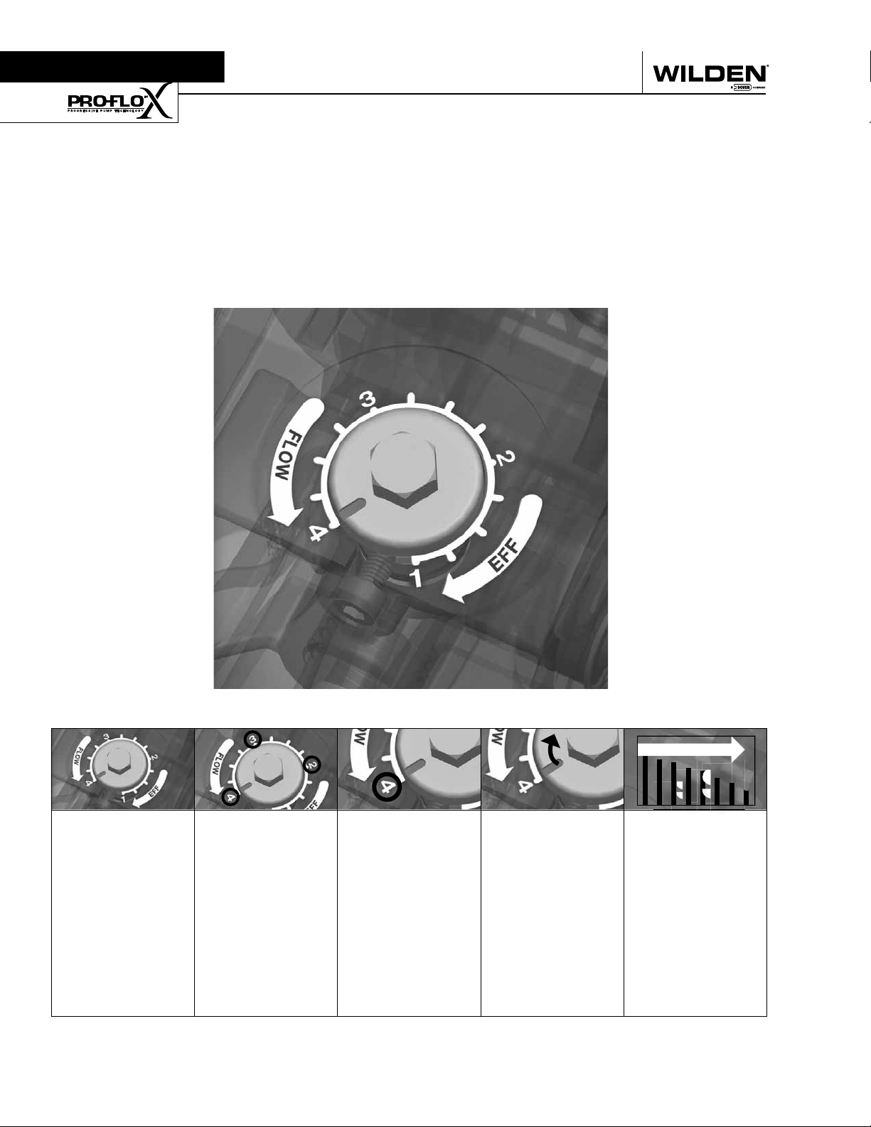
Pro-Flo X
The Pro-Flo X™ air distribution system with the
revolutionary Effi ciency Management System (EMS)
offers fl exibility never before seen in the world of
AODD pumps. The
patent-pending EMS
is simple and easy
to use. With the
turn of an integrated
TM
Operating Principal
control dial, the operator can select the optimal
balance of fl ow and effi ciency that best meets the
application needs. Pro-Flo X™ provides higher
performance, lower
operational costs
and fl exibility that
exceeds previous
industry standards.
AIR CONSUMPTION
$
$
$
Turning the dial
changes the
relationship
between air inlet
and exhaust
porting.
WILDEN PUMP & ENGINEERING, LLC 10 PX1 Performance
Each dial setting
represents an
entirely different
fl ow curve
Pro-Flo X™ pumps
are shipped from
the factory on
setting 4, which
is the highest
fl ow rate setting
possible
Moving the dial
from setting 4
causes a decrease
in fl ow and an even
greater decrease in
air consumption.
When the air
consumption
decreases more
than the fl ow
rate, effi ciency
is improved and
operating costs
are reduced.
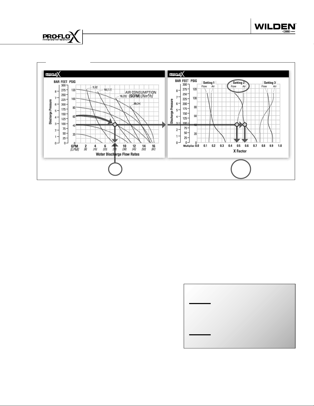
Example 1
HOW TO USE THIS EMS CURVE
SETTING 4 PERFORMANCE CURVE
Figure 1 Figure 2
Example data point = Example data point =
This is an example showing how to determine fl ow rate and
air consumption for your Pro-Flo X™ pump using the Effi ciency Management System (EMS) curve and the performance
curve. For this example we will be using 4.1 bar (60 psig) inlet
air pressure and 2.8 bar (40 psig) discharge pressure and EMS
setting 2.
Step 1:
Identifying performance at setting 4. Locate
the curve that represents the fl ow rate of the
pump with 4.1 bar (60 psig) air inlet pressure.
Mark the point where this curve crosses the
horizontal line representing 2.8 bar (40 psig)
discharge pressure. (Figure 1). After locating
your performance point on the fl ow curve,
draw a vertical line downward until reaching
the bottom scale on the chart. Identify the fl ow
rate (in this case, 8.2 gpm). Observe location
of performance point relative to air consumption curves and approximate air consumption
value (in this case, 9.8 scfm).
8.2
GPM
curve, draw vertical lines downward until
reaching the bottom scale on the chart. This
identifi es the fl ow X Factor (in this case, 0.58)
and air X Factor (in this case, 0.48).
Step 3:
Calculating performance for specific EMS
setting. Multiply the fl ow rate (8.2 gpm)
obtained in Step 1 by the fl ow X Factor multiplier (0.58) in Step 2 to determine the fl ow rate
at EMS setting 2. Multiply the air consumption (9.8 scfm) obtained in Step 1 by the air
X Factor multiplier (0.48) in Step 2 to determine the air consumption at EMS setting 2
(Figure 3).
8.2
gpm
.58
4.8
gpm
0.58
0.48
(fl ow rate for Setting 4)
(Flow X Factor setting 2)
(Flow rate for setting 2)
EMS CURVE
fl ow multiplier
air multiplier
Step 2:
Determining flow and air X Factors. Locate
your discharge pressure (40 psig) on the vertical axis of the EMS curve (Figure 2). Follow
along the 2.8 bar (40 psig) horizontal line until
intersecting both fl ow and air curves for your
desired EMS setting (in this case, setting 2).
Mark the points where the EMS curves intersect the horizontal discharge pressure line.
After locating your EMS points on the EMS
PX1 Performance 11 WILDEN PUMP & ENGINEERING, LLC
9.8
scfm
(air consumption for setting 4)
.48
4.7
Figure 3
The fl ow rate and air consumption at Setting
2 are found to be 18.2 lpm (4.8 gpm) and 7.9
Nm3/h (4.7 scfm) respectively.
(Air X Factor setting 2)
scfm
(air consumption for setting 2)
 Loading...