

Page 1
P1/PX1
Original™ Series METAL Pumps
Simplify your process
Engineering
Operation &
Maintenance
LISTED
79
WIL-103 00 -E -10
REPLACES WIL-10300- E-09
Page 2
TABLE OF CONTENTS
SECTION 1 CAUTIONS—READ FIRST! . . . . . . . . . . . . . . . . . . . . . . . . . . . . . . . . . . . . . . . . . . . . . .1
SECTION 2 WILDEN PUMP DESIGNATION SYSTEM . . . . . . . . . . . . . . . . . . . . . . . . . . . . . . . . . 2
SECTION 3 HOW IT WORKS—PUMP & AIR DISTRIBUTION SYSTEM . . . . . . . . . . . . . . . . 3
SECTION 4 DIMENSIONAL DRAWINGS . . . . . . . . . . . . . . . . . . . . . . . . . . . . . . . . . . . . . . . . . . . . .4
SECTION 5 PERFORMANCE
A. P1 Performance Curves
Rubber-Fitted . . . . . . . . . . . . . . . . . . . . . . . . . . . . . . . . . . . . . . . . . . . . . . . . . . . . . . . .6
TPE-Fitted . . . . . . . . . . . . . . . . . . . . . . . . . . . . . . . . . . . . . . . . . . . . . . . . . . . . . . . . . . .6
PTFE-Fitted . . . . . . . . . . . . . . . . . . . . . . . . . . . . . . . . . . . . . . . . . . . . . . . . . . . . . . . . . . 7
B. PX1 Performance
Operating Principal . . . . . . . . . . . . . . . . . . . . . . . . . . . . . . . . . . . . . . . . . . . . . . . . . . 10
How to Use this EMS Curve . . . . . . . . . . . . . . . . . . . . . . . . . . . . . . . . . . . . . . . . . . . 11
Performance Curves
Rubber-Fitted . . . . . . . . . . . . . . . . . . . . . . . . . . . . . . . . . . . . . . . . . . . . . . . . . . . . 14
TPE-Fitted . . . . . . . . . . . . . . . . . . . . . . . . . . . . . . . . . . . . . . . . . . . . . . . . . . . . . . .15
PTFE-Fitted . . . . . . . . . . . . . . . . . . . . . . . . . . . . . . . . . . . . . . . . . . . . . . . . . . . . . .16
C. Suction Lift Curves . . . . . . . . . . . . . . . . . . . . . . . . . . . . . . . . . . . . . . . . . . . . . . . . . . . . 19
SECTION 6 SUGGESTED INSTALLATION, OPERATION & TROUBLESHOOTING . . . . . . . 20
SECTION 7 ASSEMBLY / DISASSEMBLY . . . . . . . . . . . . . . . . . . . . . . . . . . . . . . . . . . . . . . . . . . .23
Grounding Strap for CSA Pumps . . . . . . . . . . . . . . . . . . . . . . . . . . . . . . . . . . . . . . . . . . . 25
SECTION 8 EXPLODED VIEW & PARTS LISTING
P1 Rubber/TPE-Fitted . . . . . . . . . . . . . . . . . . . . . . . . . . . . . . . . . . . . . . . . . . . . . . . . . . . . .30
P1 PTFE-Fitted . . . . . . . . . . . . . . . . . . . . . . . . . . . . . . . . . . . . . . . . . . . . . . . . . . . . . . . . . . .32
PX1 Rubber-Fitted . . . . . . . . . . . . . . . . . . . . . . . . . . . . . . . . . . . . . . . . . . . . . . . . . . . . . . . .34
PX1 PTFE-Fitted . . . . . . . . . . . . . . . . . . . . . . . . . . . . . . . . . . . . . . . . . . . . . . . . . . . . . . . . .36
SECTION 9 ELASTOMER OPTIONS . . . . . . . . . . . . . . . . . . . . . . . . . . . . . . . . . . . . . . . . . . . . . . . . .38
O
z
o
I
I
n
USE
e
t
i
n
g
e
s
e
c
n
a
t
s
b
u
S
&
I
s
s
a
l
C
NON
U.S. Clean Air Act
Amendments of 1990
D
e
p
l
Page 3
Section 1
CAUTIONS—READ FIRST!
CAUTION: Do not apply compressed air to the exhaust port
— pump will not function.
CAUTION: Do not over-lubricate air supply — excess
lubrication will reduce pump performance. Pump is pre-lubed.
CAUTION: Do not under any circums tance loosen the set
screw located at the adjuster dial of the Pro-Flo X ™ pump. If
the set screw is loose when the pump is pressurized, it could
eject and cause injury to anyone in the area.
TEMPERATURE LIMITS:
Neoprene –17.7°C to 93.3°C 0°F to 200°F
Buna-N –12.2°C to 82.2°C 10°F to 180°F
EPDM –51.1°C to 137.8°C –60°F to 280°F
Viton
®
–40°C to 176.7°C –40°F to 350°F
Sanifl ex™ –28.9°C to 104.4°C –20°F to 220°F
Polytetrafl uoroethylene (PTFE)
4.4°C to 104.4°C 40°F to 220°F
Polyurethane –12.2°C to 65.6°C 10°F to 150°F
Tetr a - Flex™ P T FE w/ Neop r ene B acke d
4.4°C to 107.2°C 40°F to 225°F
Tetr a - Flex™ P T FE w/ EPDM Backe d
-10°C to 137°C 14°F to 280°F
NOTE: Not all materials are available for all models. Refer to
Section 2 for material options for your pump.
NOTE: Canadian Standards Association ( CSA) confi gured
pumps should not be used in temperatures lower than 0.0ºC to
51.6 ºC ( 32 ºF to 125ºF).
NOTE: UL listed confi gured pumps have the following
temperature limits:
UL 79 Buna- -12.2 °C (10 °F) to 52°C (12 5°F)
CAUTION: When choosing pump materials, be sure to check
the temperature limits for all wetted components. Example:
®
Viton
has a max imum limi t of 176 .7°C ( 350 °F) b ut poly propyle ne
has a maximum limit of only 79 °C (17 5°F).
CAUTION: Maximum temperature limits are based upon
mechanical stress only. Certain chemicals will signi fi cantly
reduce maximum safe operating temperatures. Consult
Chemical Resis tance Guide (E4) for chemical compatibility and
temperature limits.
WARNING: Prevention of stat ic sparking — If static sparking
occurs, fi re or explosion could result. Pump, valves, and
containers must be grounded to a proper grounding point when
handling fl ammable fl uids and whenever discharge of static
electricity is a hazard.
CAUTION: Canadian St andards Association (C SA) confi gured
pumps must be electrically grounded using the grounding
location identifi ed. Improper grounding can cause improper
and dangerous operation.
CAUTION: Do not exceed 8.6 bar (12 5 psig ) air supply
pressure.
CAUTION: Canadian St andards Association (C SA) confi gured
pumps should not exceed 6.9 bar (10 0 psig ) sweet gas supply
pressure.
CAUTION: For U.L. listed pumps, do not exceed 3.4 bar (50
psig) air supply pressure.
CAUTION: The process fl uid and cleaning fl uids must be
chemically compatible with all wetted pump components.
Consult Chemical Resistance Guide (E4).
CAUTION: Do not exceed 82°C (180°F) air inlet temperature
for Pro-Flo X™ models.
CAUTION: Pumps should be thoroughly fl ushed before
installing into process lines. FDA and USDA approved pumps
should be cleaned and/or sanitized before being used.
CAUTION: Always wear safety glasses when operating
pump. If diaphragm rupture occurs, material being pumped may
be forced out air exhaust.
CAUTION: Before any maintenance or repair is attempted,
the compressed air line to the pump should be disconnected
and all air pressure allowed to bleed from pump. Disconnect
all intake, discharge and air lines. Drain the pump by turning
it upside down and allowing any fl uid to fl ow into a suitable
container.
CAUTION: Blow out air line for 10 to 20 seconds before
attaching to pump to make sure all pipeline debris is clear. Use
an in-line air fi l ter. A 5µ ( micron) air fi lter is recommended.
NOTE: When installing PTFE diaphragms, it is important
to tighten outer pistons simultaneously (turning in opposite
directions) to ensure tight fi t. (See torque specifi cations in
Section 7.)
NOTE: Cast Iron PTFE-fi tted pumps come standard from the
factory with expanded P TFE gaskets ins talled in the diaphragm
bead of the liquid chamber. PTFE gaskets cannot be re-used.
Consult PS-TG for installation instructions during reassembly.
NOTE: Before starting disassembly, mark a line from each
liquid chamber to i ts corresponding air chamber. This line will
assis t in proper alignment during reassembly.
CAUTION: Pro-Flo® pumps cannot be used in submersible
applications. Pro-Flo X™ is available in both submersible and
non-submersible options. Do not use non-submersible Pro-Flo
X™ models in submersible applications. Turbo-Flo
also be used in submersible applications.
CAUTION: Tighten all hardware prior to installation.
CAUTION: The gas outlet of CSA confi gured pumps must be
vented to a safe location in accordance with local codes or, in
the absence of local codes, an industry or nationally recognized
code having jurisdiction over the specifi ed ins tallation.
CAUTION: Fo r U.L. li sted pum ps, all pipe co nnectio ns are to be
made using U.L. classi fi ed gasoline-resis tant pipe compound.
CAUTION: F or U. L . l i st ed pu m ps al l i ns t al la t io ns mu s t co n fo rm
to NFPA 30, NFPA 30A, and all other applicable codes.
CAUTION: For U.L. listed pumps, air exhaust port is to be
connected to pipe or tubing to be routed outdoors or other
location determined to be equivalent.
CAUTION: For U.L. listed pumps, pump is to be grounded
using the jam-nut located at the top of the long vertical carriage
bolt . The ground connection is marked with a tag having the
grounding symbol.
®
pumps can
Grounding Symbol
WIL-10300-E-09 1 WILDEN PUMP & ENGINEERING, LLC
Page 4
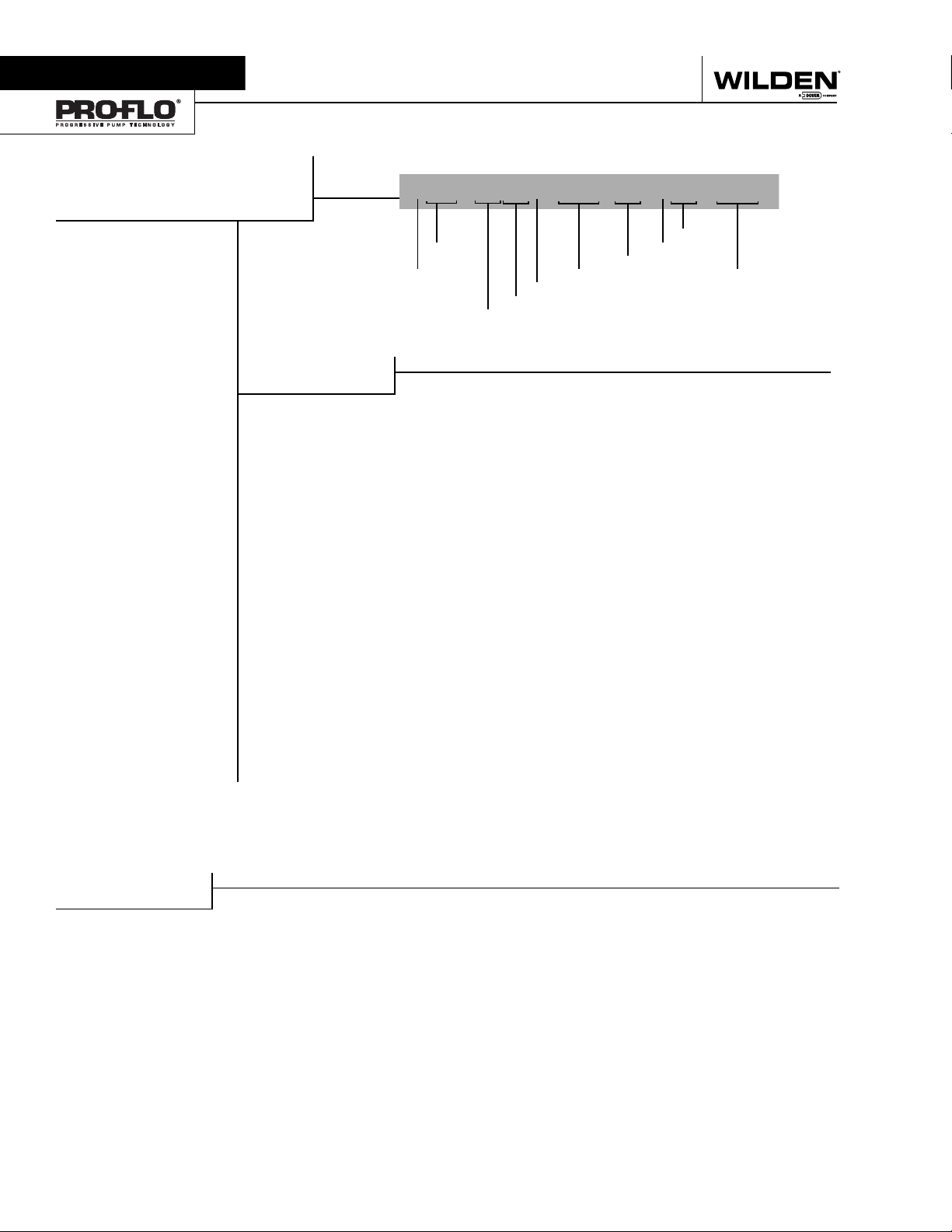
Section 2
WILDEN PUMP DESIGNATION SYSTEM
P1/PX1 ORIGINAL™
METAL
13 mm (½") Pump
Maximum Flow Rate:
62.8 lpm (16.6 gpm)
MATERIAL CODES
MODEL
P1 = Pro-Flo
PX1 = Pro-Flo X™
XPI = ATEX Pro-Flo
WETTED PARTS & OUTER PISTON
AA = ALUMINUM / ALUMINUM
AZ = ALUMINUM / NO PISTON
SS = STAINLESS STEEL /
SZ = STAINLESS STEEL /
CENTER SECTION
AA = ALUMINUM (PX1 only)
GG = CONDUCTIVE ACETAL
(P1 only)
JJ = CONDUCTIVE
LL = ACETAL (P1 only)
PP = POLYPROPYLENE (P1 only)
LEGEND
®
®
STAINLESS STEEL
NO PISTON
POLYPROPYLENE (P1 only)
xPX1 / XXXXX / XXX /XX/ XXX / XXXX
MODEL VALVE SEAT
ATEX DIAPHRAGMS
WETTED PARTS & OUTER PISTON
AIR VALVE
A = ALUMINUM (PX1 only)
G =
CONDUCTIVE ACETAL
only)
J = CONDUCTIVE
POLYPROPYLENE (P1 only)
L = ACETAL (P1 only)
P = POLYPROPYLENE (P1 only)
DIAPHRAGMS
XBS = CONDUCTIVE BUNA-N
(Two Red Dots)
BNS = BUNA-N (Red Dot)
FSS = SANIFLEX™
[Hytrel
PUS = POLYURETHANE (Clear)
TEU = PTFE w/EPDM
BACK-UP (White)
THU = PTFE W/HIGH-TEMP
BUNA-N BACK-UP (White)
TNU = PTFE W/NEOPRENE
BACK-UP (White)
TNL = PTFE W/NEOPRENE
BACK-UP O-RING,
IPD (White)
VTS = VITON
WFS = WIL-FLEX™ [Santoprene
(Orange Dot)]
ESD = BUNA-N
AIR VALVE
CENTER SECTION
(P1
®
(Cream)]
®
(White Dot)
VALVE BALLS
VALVE BALL
BN = BUNA-N (Red Dot)
FS = SANIFLEX™
PU = POLYURETHANE (Brown)
TF = PTFE (White)
VT = VITON
WF = WIL-FLEX™ [Santoprene
VALVE SEAT
A = ALUMINUM
S = STAINLESS STEEL
V = VITON
VALVE SEAT O-RING
BN = BUNA-N
FS = SANIFLEX™
PU = POLYURETHANE (Brown)
TF = PTFE (White)
WF = WIL-FLEX™ [Santoprene
®
O-RINGS
®
[Hytrel
(Cream)]
®
(White Dot)
(Orange Dot)]
®
(White Dot)
®
[Hytrel
(Cream)]
SPECIALTY
CODE
(if applicable)
®
®
]
SPECIALTY CODES
0023 Wing nuts
0067 Saniflo™ FDA, Wil-Gard II™ 220V
0070 Saniflo™ FDA
0079 Tri-clamp fittings, wing nuts
0080 Tri-clamp fittings ONLY
0100 Wil-Gard II™ 110V
0102 Wil-Gard II™ sensor wires ONLY
0103 Wil-Gard II™ 220V
NOTE: The Wilden UL 79 Listed products covered by this manual are PX1 models followed by AA or SS, followed by AA, followed by A, followed by
BNS, followed by BN, followed by A or S, followed by BN, followed by 0495. Wilden UL Listed pumps have been evaluated for use at a
25 C (77F ) ambient temperature with a maximum inlet pressure of 3.4 Bar (50 PSI)..
WILDEN PUMP & ENGINEERING, LLC 2 WIL-10300-E-10
0120 Saniflo™ FDA, Wil-Gard II™ 110V
0206 PFA coated hardware, Wil-Gard II™
sensor wires ONLY
0495 U.L. Approved
0502 PFA coated hardware
0603 PFA coated hardware, Wil Gard 110V
0608 PFA coated hardware, Wil Gard 220V
Page 5
Section 3
HOW IT WORKS
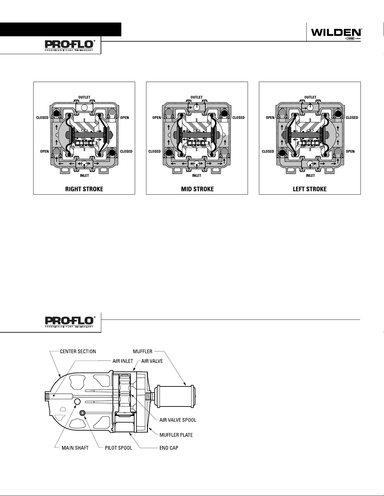
The Wilden diaphragm pump is an air-operated, positive displacement, self-priming pump. These drawings show the flow pattern
through the pump upon its initial stroke. It is assumed the pump has no fluid in it prior to its initial stroke.
BA B A BA
OPEN
FIGURE 1 The air valve directs pressurized air to
the back side of diaphragm A. The compressed air
is applied directly to the liquid column separated by
elastomeric diaphragms. The diaphragm acts as a
separation membrane between the compressed air
and liquid, balancing the load and removing mechanical stress from the diaphragm. The compressed air
moves the diaphragm away from the center block of
the pump. The opposite diaphragm is pulled in by
the shaft connected to the pressurized diaphragm.
Diaphragm B is on its suction stroke; air behind the
diaphragm has been forced out to the atmosphere
through the exhaust port of the pump. The movement of diaphragm B toward the center block of the
pump creates a vacuum within chamber B. Atmospheric pressure forces fluid into the inlet manifold
forcing the inlet valve ball off its seat. Liquid is free
to move past the inlet valve ball and fill the liquid
chamber (see shaded area).
HOW IT WORKS—AIR DISTRIBUTION SYSTEM
FIGURE 2 When the pressurized diaphragm,
diaphragm A, reaches the limit of its discharge
stroke, the air valve redirects pressurized air to the
back side of diaphragm B. The pressurized air forces
diaphragm B away from the center block while pulling diaphragm A to the center block. Diaphragm B
is now on its discharge stroke. Diaphragm B forces
the inlet valve ball onto its seat due to the hydraulic
forces developed in the liquid chamber and manifold of the pump. These same hydraulic forces
lift the discharge valve ball off its seat, while the
opposite discharge valve ball is forced onto its seat,
forcing fluid to flow through the pump discharge.
The movement of diaphragm A toward the center
block of the pump creates a vacuum within liquid
chamber A. Atmospheric pressure forces fluid into
the inlet manifold of the pump. The inlet valve ball is
forced off its seat allowing the fluid being pumped
to fill the liquid chamber.
®
The Pro -Flo
patented air distribution system incorporates two
moving parts : the air valve spool and the pilot spool. The hear t of
the system is the air valve spool and air valve. This valve design
incorporates an unbalanced spool. The smaller end of the spool
is pressurized continuously, while the large end is alternately
pressurized then exhausted to move the spool. The spool direc ts
pressurized air to one air chamber while exhausting the other.
The air causes the main shaft/diaphragm assembly to shift to
one side — discharging liquid on that side and pulling liquid in
on the other side. When the shaft reaches the end of its stroke,
the inner piston actuates the pilot spool, which pressurizes and
exhausts the large end of the air valve spool. The repositioning
of the air valve spool routes the air to the other air chamber.
FIGURE 3 At completion of the stroke, the air valve
again redirects air to the back side of diaphragm A,
which starts diaphragm B on its exhaust stroke. As
the pump reaches its original starting point, each
diaphragm has gone through one exhaust and one
discharge stroke. This constitutes one complete
pumping cycle. The pump may take several cycles
to completely prime depending on the conditions of
the application.
WIL-10300-E-10 3 WILDEN PUMP & ENGINEERING, LLC
Page 6
Section 4
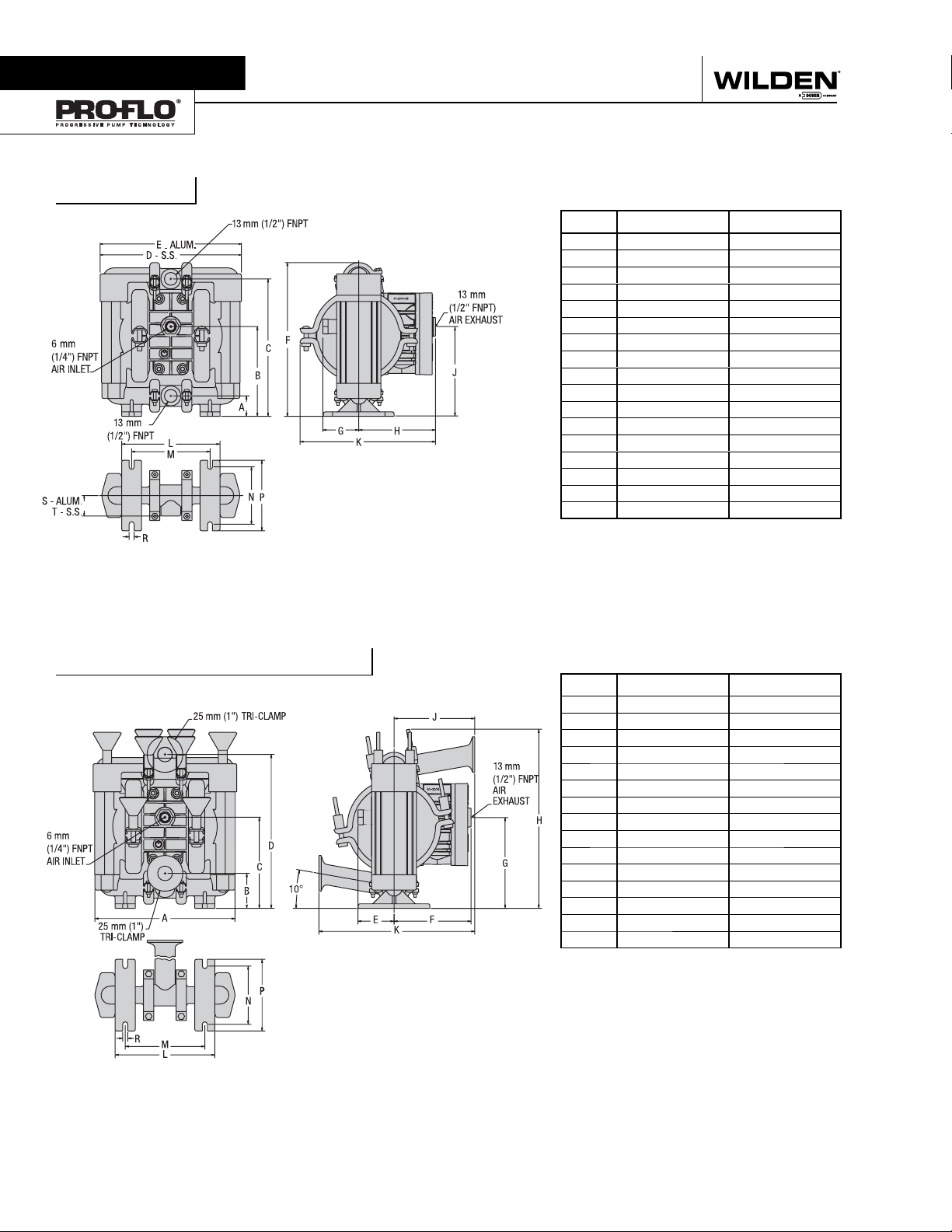
DIMENSIONAL DRAWINGS
P1 METAL
DIMENSIONS
ITEM METRIC (mm) STANDARD (inch)
A 29 1.1
B 129 5.1
C 199 7.8
D 203 8.0
E 207 8.2
F 222 8.8
G 56 2.2
H 115 4.5
J 129 5.1
K 205 8.1
L 140 5.5
M 112 4.4
N 83 3.3
P 102 4.0
R 7 0.3
S 30 1.2
T 30 1.2
BSP threads available.
P1 METAL SANIFLO
FDA
DIMENSIONS
ITEM METRIC (mm) STANDARD (inch)
A 204 8.0
B 48 1.9
C 132 5.2
D 221 8.7
E 53 2.1
F 115 4.5
G 125 4.9
H 258 10.2
J 116 4.6
K 229 9.0
L 143 5.6
M 114 4.5
N 83 3.3
P 102 4.0
R 7 0.3
WILDEN PUMP & ENGINEERING, LLC 4 WIL-10300-E-10
Page 7
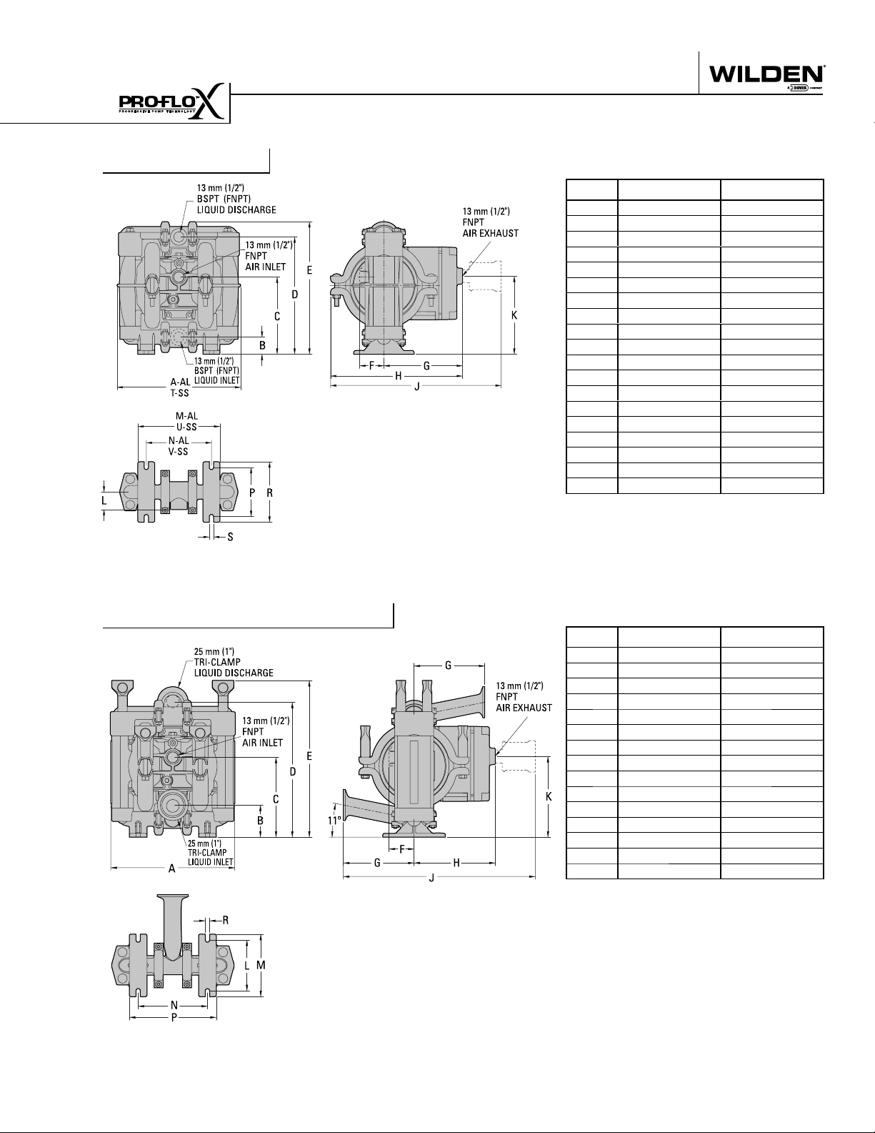
DIMENSIONAL DRAWINGS
PX1 METAL
DIMENSIONS
ITEM METRIC (mm) STANDARD (inch)
A 208 8.2
B 28 1.1
C 130 5.1
D 198 7.8
E 224 8.8
F 41 1.6
G 132 5.2
H 221 8.7
J 361 14.2
K 132 5.2
L 30 1.2
M 137 5.4
N 109 4.3
P 84 3.3
R 102 4.0
S 8 0.3
T 203 8.0
U 142 5.6
V 112 4.4
BSP threads available.
PX1 METAL SANIFLO
FDA
DIMENSIONS
ITEM METRIC (mm) STANDARD (inch)
A 203 8.0
B 53 2.1
C 130 5.1
D 218 8.6
E 257 10.1
F 41 1.6
G 114 4.5
H 132 5.2
J 386 15.2
K 132 5.2
L 84 3.3
M 102 4.0
N 112 4.4
P 142 5.6
R 8 0.3
WIL-10300-E-10 5 WILDEN PUMP & ENGINEERING, LLC
Page 8
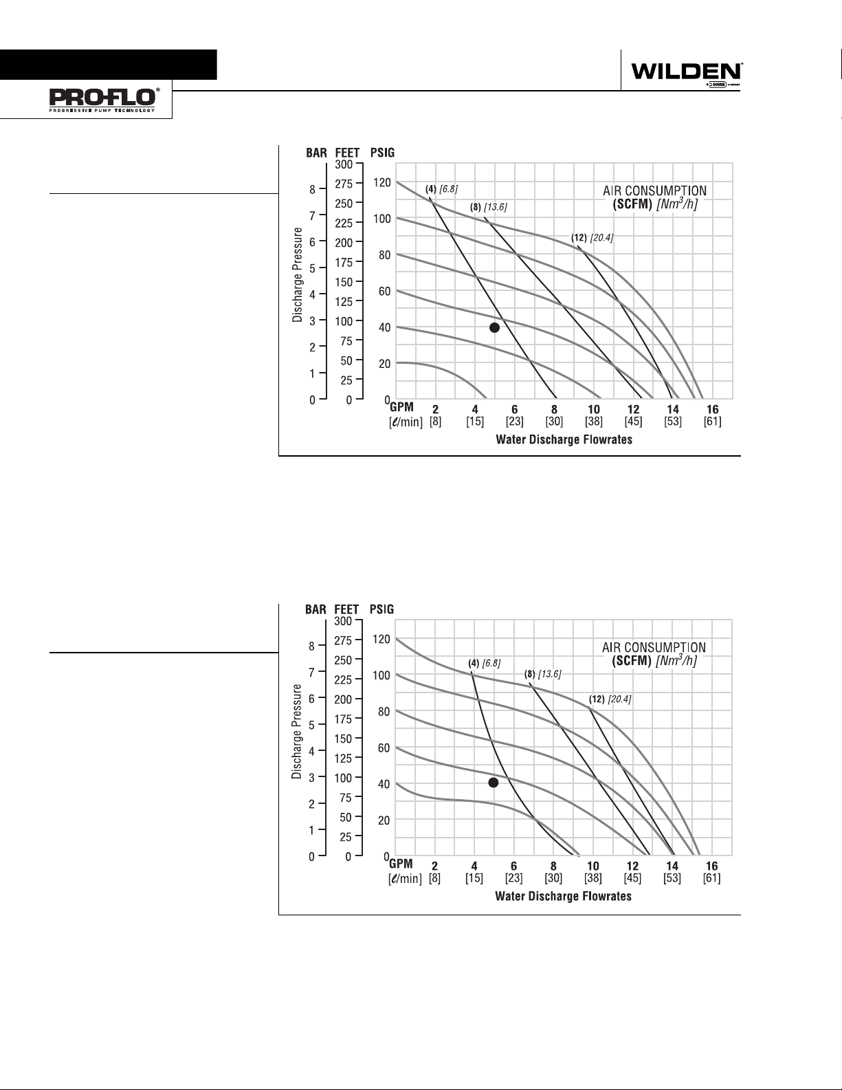
Section 5A
PERFORMANCE
P1 METAL
RUBBER-FITTED
Height .................................... 222 mm (8.8")
Width .....................................207 mm (8.2")
Depth .................................... 205 mm (8.1")
Ship Weight .................
Air Inlet ......................................6 mm (1/4")
Inlet .........................................13 mm (1/2")
Outlet ......................................13 mm (1⁄2")
Suction Lift ........................ 5.8 m Dry (19.0')
Displacement per Stroke . .11 l (0.029 gal.)
Max. Flow Rate ........... 58.67 lpm (15.5 gpm)
Max. Size Solids ................. 1.59 mm (1/16")
1
Displacement per stroke was calculated at 4.8 Bar
(70 psig) air inlet pressure against a 2 Bar (30 psig)
head pressure.
Example: To pump 18.9 lpm (5 gpm) against
a discharge pressure head of 2.7 Bar (40
psig) requires 4 Bar (60 psig) and 5.92 Nm
(3.5 scfm) air consumption. (See dot on
chart.)
Caution: Do not exceed 8.6 Bar (125 psig) air
supply pressure.
Aluminum 6 kg (13 lbs)
Stainless Steel 9 kg (20 lbs)
9.5 m Wet (31.0')
1
3
/h
Flow rates indicated on chart were determined by pumping water.
For optimum life and performance, pumps should be specified so that daily operation parameters
will fall in the center of the pump performance curve.
P1 METAL
TPE-FITTED
Height .................................... 222 mm (8.8")
Width .....................................207 mm (8.2")
Depth .................................... 205 mm (8.1")
Ship Weight .................
Air Inlet ......................................6 mm (1/4")
Inlet .........................................13 mm (1/2")
Outlet ......................................13 mm (1/2")
Suction Lift ........................ 5.2 m Dry (17.0')
Displacement per Stroke . .11 l (0.029 gal.)
Max. Flow Rate ........... 58.30 lpm (15.4 gpm)
Max. Size Solids ................. 1.59 mm (1/16")
1
Displacement per stroke was calculated at 4.8 Bar
(70 psig) air inlet pressure against a 2 Bar (30 psig)
head pressure.
Example: To pump 18.9 lpm (5 gpm) against
a discharge pressure head of 2.7 Bar (40
psig) requires 4 Bar (60 psig) and 5.92 Nm
(3.5 scfm) air consumption. (See dot on
chart.)
Caution: Do not exceed 8.6 Bar (125 psig) air
supply pressure.
Aluminum 6 kg (13 lbs)
Stainless Steel 9 kg (20 lbs)
9.5 m Wet (31.0')
3
/h
1
Flow rates indicated on chart were determined by pumping water.
For optimum life and performance, pumps should be specified so that daily operation parameters
will fall in the center of the pump performance curve.
WILDEN PUMP & ENGINEERING, LLC 6 WIL-10300-E-10
Page 9

PERFORMANCE
P1 METAL
PTFE-FITTED
Height .................................... 222 mm (8.8")
Width .....................................207 mm (8.2")
Depth .................................... 205 mm (8.1")
Ship Weight .................
Air Inlet ......................................6 mm (1/4")
Inlet .........................................13 mm (1/2")
Outlet ......................................13 mm (1/2")
Suction Lift ........................ 4.9 m Dry (16.0')
Displacement per Stroke . .09 l (0.025 gal.)
Max. Flow Rate ........... 54.41 lpm (14.4 gpm)
Max. Size Solids ................. 1.59 mm (1/16")
1
Displacement per stroke was calculated at 4.8 Bar
(70 ) air inlet pressure against a 2 Bar (30 psig)
head pressure.
Example: To pump 18.9 lpm (5 gpm) against
a discharge pressure head of 2.7 Bar (40
psig) requires 4 Bar (60 psig) and 5.92 Nm
(3.5 scfm) air consumption. (See dot on
chart.)
Caution: Do not exceed 8.6 Bar (125 psig) air
supply pressure.
Aluminum 6 kg (13 lbs)
Stainless Steel 9.2 kg (20 lbs)
9.5 m Wet (31.0')
1
3
/h
Flow rates indicated on chart were determined by pumping water.
For optimum life and performance, pumps should be specified so that daily operation parameters
will fall in the center of the pump performance curve.
WIL-10300-E-10 7 WILDEN PUMP & ENGINEERING, LLC
Page 10
Finding
Spares
A
Nightmare
?
Sleep easier with
Spectrom is not your typical after market part
supplier. We do not simply sell pump parts; we
PRODUCTS:
AODDP
(Air Operated Double
Diaphragm Pumps)
• Warren-Rupp
®
• ARO
• Other
PUMP PARTS
(Low Cost)
• Diaphragms
• Valve balls
• Valve seats
®
provide value added procurement solutions.
Our unique network enables us to purchase effectively, resulting in low cost
solutions. We also know that low purchase
price is not enough - quality, integrity and
inventory are also important. Spectrom is struc-
tured to provide Pre and Post sales support, giving
our customers value added application and pump
knowledge.
Contact us to have a procurement solution
developed for you. We don’t just fit you
into a generic system, we develop specific
solutions that achieve results.
Spectrom will ship your order from
our facility within 3 working days!
KNOWLEDGE
& SERVICE
• Competitive pricing
• Delivery
• Service
• Inventory
1-909-512-1261 www.spectromparts.com
WILDEN PUMP & ENGINEERING, LLC 8 WIL-10300-E-10
WARNING: These parts may exhibit
better life than OEM parts.
Page 11
PX1
M E T A L
PX1 PERFORMANCE
Page 12
Section 5B
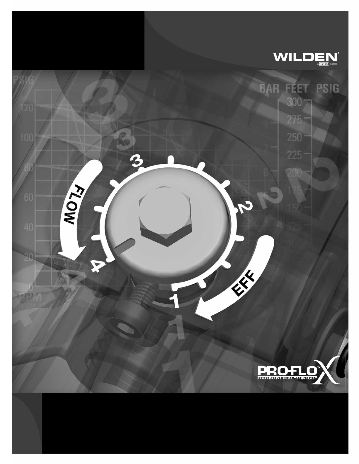
Pro-Flo X
The Pro-Flo X™ air distribution system with the
revolutionary Effi ciency Management System (EMS)
offers fl exibility never before seen in the world of
AODD pumps. The
patent-pending EMS
is simple and easy
to use. With the
turn of an integrated
TM
Operating Principal
control dial, the operator can select the optimal
balance of fl ow and effi ciency that best meets the
application needs. Pro-Flo X™ provides higher
performance, lower
operational costs
and fl exibility that
exceeds previous
industry standards.
AIR CONSUMPTION
$
$
$
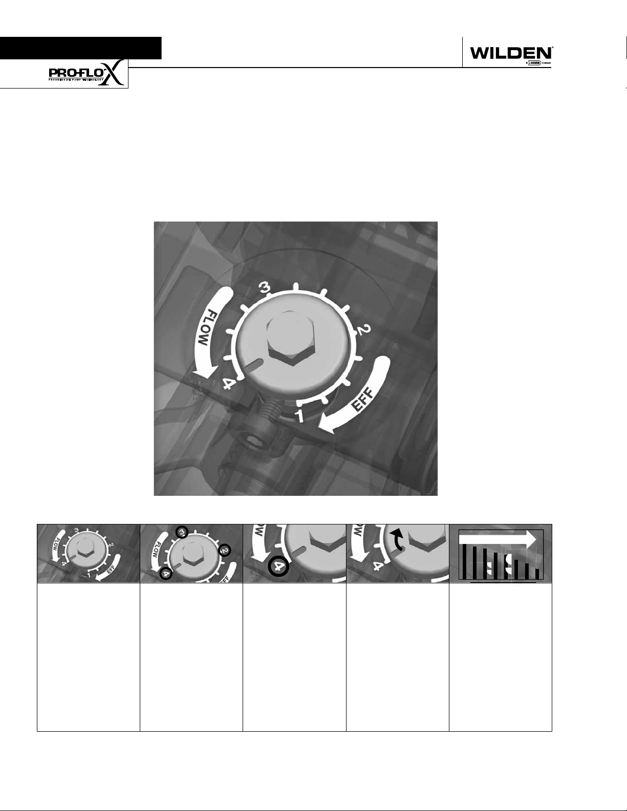
Turning the dial
changes the
relationship
between air inlet
and exhaust
porting.
WILDEN PUMP & ENGINEERING, LLC 10 PX1 Performance
Each dial setting
represents an
entirely different
fl ow curve
Pro-Flo X™ pumps
are shipped from
the factory on
setting 4, which
is the highest
fl ow rate setting
possible
Moving the dial
from setting 4
causes a decrease
in fl ow and an even
greater decrease in
air consumption.
When the air
consumption
decreases more
than the fl ow
rate, effi ciency
is improved and
operating costs
are reduced.
Page 13
Example 1
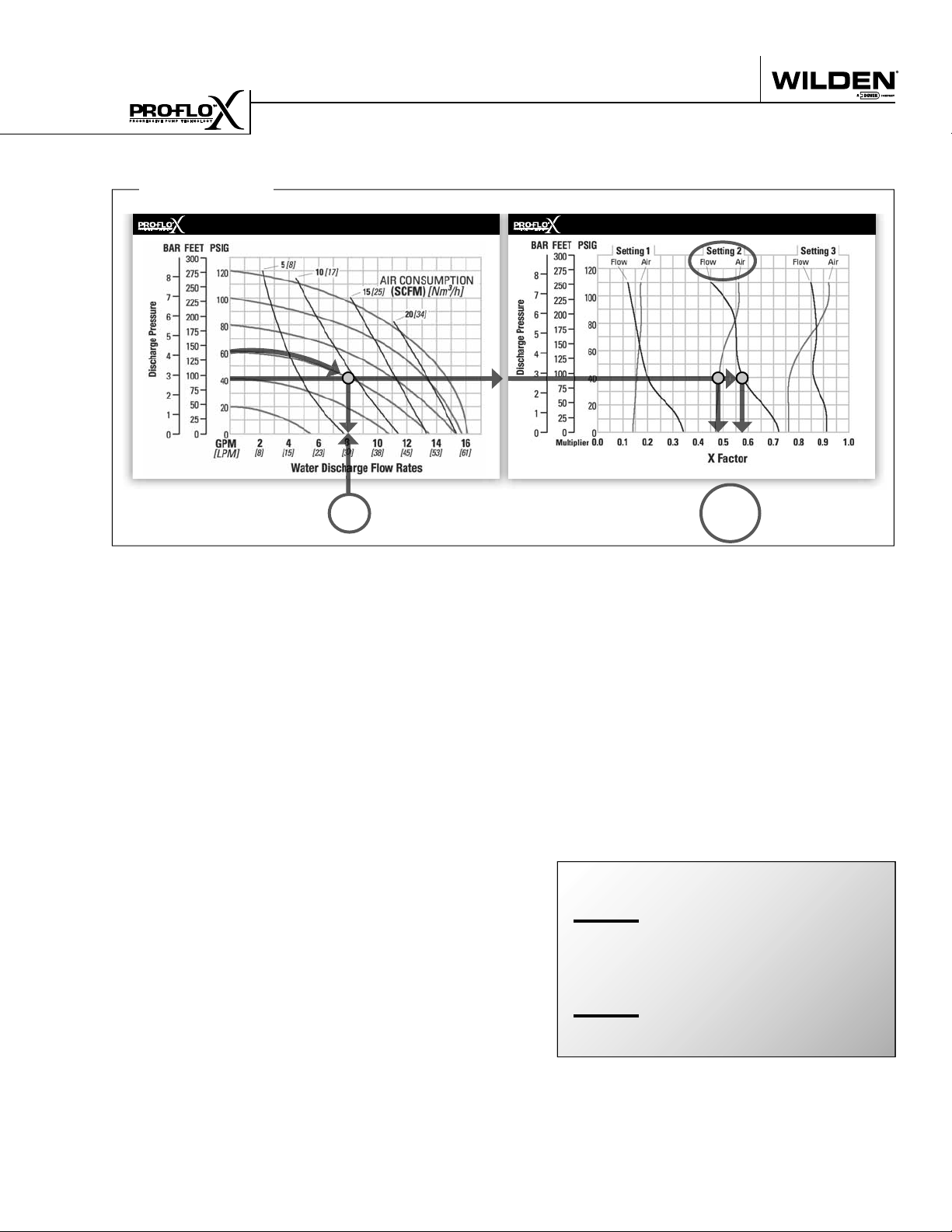
HOW TO USE THIS EMS CURVE
SETTING 4 PERFORMANCE CURVE
Figure 1 Figure 2
Example data point = Example data point =
This is an example showing how to determine fl ow rate and
air consumption for your Pro-Flo X™ pump using the Effi ciency Management System (EMS) curve and the performance
curve. For this example we will be using 4.1 bar (60 psig) inlet
air pressure and 2.8 bar (40 psig) discharge pressure and EMS
setting 2.
Step 1:
Identifying performance at setting 4. Locate
the curve that represents the fl ow rate of the
pump with 4.1 bar (60 psig) air inlet pressure.
Mark the point where this curve crosses the
horizontal line representing 2.8 bar (40 psig)
discharge pressure. (Figure 1). After locating
your performance point on the fl ow curve,
draw a vertical line downward until reaching
the bottom scale on the chart. Identify the fl ow
rate (in this case, 8.2 gpm). Observe location
of performance point relative to air consumption curves and approximate air consumption
value (in this case, 9.8 scfm).
8.2
GPM
curve, draw vertical lines downward until
reaching the bottom scale on the chart. This
identifi es the fl ow X Factor (in this case, 0.58)
and air X Factor (in this case, 0.48).
Step 3:
Calculating performance for specific EMS
setting. Multiply the fl ow rate (8.2 gpm)
obtained in Step 1 by the fl ow X Factor multiplier (0.58) in Step 2 to determine the fl ow rate
at EMS setting 2. Multiply the air consumption (9.8 scfm) obtained in Step 1 by the air
X Factor multiplier (0.48) in Step 2 to determine the air consumption at EMS setting 2
(Figure 3).
8.2
gpm
.58
4.8
gpm
0.58
0.48
(fl ow rate for Setting 4)
(Flow X Factor setting 2)
(Flow rate for setting 2)
EMS CURVE
fl ow multiplier
air multiplier
Step 2:
Determining flow and air X Factors. Locate
your discharge pressure (40 psig) on the vertical axis of the EMS curve (Figure 2). Follow
along the 2.8 bar (40 psig) horizontal line until
intersecting both fl ow and air curves for your
desired EMS setting (in this case, setting 2).
Mark the points where the EMS curves intersect the horizontal discharge pressure line.
After locating your EMS points on the EMS
PX1 Performance 11 WILDEN PUMP & ENGINEERING, LLC
9.8
scfm
(air consumption for setting 4)
.48
4.7
Figure 3
The fl ow rate and air consumption at Setting
2 are found to be 18.2 lpm (4.8 gpm) and 7.9
Nm3/h (4.7 scfm) respectively.
(Air X Factor setting 2)
scfm
(air consumption for setting 2)
Page 14

HOW TO USE THIS EMS CURVE
Example 2.1
SETTING 4 PERFORMANCE CURVE
Figure 4
Example data point =
This is an example showing how to determine the inlet air
pressure and the EMS setting for your Pro-Flo X™ pump to
optimize the pump for a specifi c application. For this example we will be using an application requirement of 18.9 lpm
(5 gpm) fl ow rate against 2.8 bar (40 psig) discharge pressure.
This example will illustrate how to calculate the air consumption that could be expected at this operational point.
10.2
gpm
DETERMINE EMS SETTING
Step 1
: Establish inlet air pressure. Higher air pres-
sures will typically allow the pump to run
more effi ciently, however, available plant air
pressure can vary greatly. If an operating
pressure of 6.9 bar (100 psig) is chosen when
EMS Flow
Settings 1 & 2
0.49
In our example it is 38.6 lpm (10.2 gpm). This
is the setting 4 fl ow rate. Observe the location of the performance point relative to air
consumption curves and approximate air
consumption value. In our example setting
4 air consumption is 24 Nm3/h (14 scfm).
See fi gure 4.
Step 3
: Determine flow X Factor. Divide the required
fl ow rate 18.9 lpm (5 gpm) by the setting 4 fl ow
rate 38.6 lpm (10.2 gpm) to determine the fl ow
X Factor for the application.
5
gpm / 10.2 gpm = 0.49 (flow X Factor)
EMS CURVE
Figure 5
fl ow multiplier
plant air frequently dips to 6.2 bar (90 psig)
Step 4
pump performance will vary. Choose an operating pressure that is within your compressed
air systems capabilities. For this example we
will choose 4.1 bar (60 psig).
: Determine EMS setting from the flow
X Factor. Plot the point representing the fl ow
X Factor (0.49) and the application discharge
pressure 2.8 bar (40 psig) on the EMS curve.
This is done by following the horizontal 2.8
Step 2
: Determine performance point at setting 4. For
this example an inlet air pressure of 4.1 bar
(60 psig) inlet air pressure has been chosen.
Locate the curve that represents the performance of the pump with 4.1 bar (60 psig) inlet
air pressure. Mark the point where this curve
crosses the horizontal line representing 2.8
bar (40 psig) discharge pressure. After locating this point on the fl ow curve, draw a vertical line downward until reaching the bottom
scale on the chart and identify the fl ow rate.
bar (40 psig) psig discharge pressure line until
it crosses the vertical 0.49 X Factor line. Typically, this point lies between two fl ow EMS
setting curves (in this case, the point lies between the fl ow curves for EMS setting 1 and
2). Observe the location of the point relative
to the two curves it lies between and approximate the EMS setting (fi gure 5). For more precise results you can mathematically interpolate between the two curves to determine the
optimal EMS setting.
For this example the EMS setting is 1.8.
WILDEN PUMP & ENGINEERING, LLC 12 PX1 Performance
Page 15

HOW TO USE THIS EMS CURVE
Example 2.2
SETTING 4 PERFORMANCE CURVE
Figure 6
Example data point =
10.2
gpm
Determine air consumption at a specific
EMS setting.
Step 1
: Determine air X Factor. In order to determine
the air X Factor, identify the two air EMS setting curves closest to the EMS setting established in example 2.1 (in this case, the point lies
between the air curves for EMS setting 1 and
2). The point representing your EMS setting
(1.8) must be approximated and plotted on the
EMS curve along the horizontal line representing your discharge pressure (in this case, 40
psig). This air point is different than the fl ow
point plotted in example 2.1. After estimating
(or interpolating) this point on the curve, draw
a vertical line downward until reaching the
bottom scale on the chart and identify the air
X Factor (fi gure 7).
EMS CURVE
EMS Air
Settings 1 & 2
Figure 7
Example data point =
Step 2
: Determine air consumption. Multiply your
setting 4 air consumption (14 scfm) value by
the air X Factor obtained above (0.40) to determine your actual air consumption.
1
4 scfm x 0.40 = 5.6 SCFM
In summary, for an application requiring 18.9 lpm
(5 gpm) against 2.8 bar (40 psig) discharge pressure,
the pump inlet air pressure should be set to 4.1 bar
(60 psig) and the EMS dial should be set to 1.8. The
pump would then consume 9.5 Nm3/h (5.6 scfm) of
compressed air.
0.40
air multiplier
For this example the air X Factor is 0.40
PX1 Performance 13 WILDEN PUMP & ENGINEERING, LLC
Page 16

EMS CURVE
PERFORMANCE
/h (21.0
3
EXAMPLE
A PX1 metal, Rubber-fi tted pump operating at EMS setting 4,
achieved a fl ow rate of 56.8 lpm (15.0 gpm) using 35.7 Nm
scfm) of air when run at 5.5 bar (80 psig) air inlet pressure and 1.4
bar (20 psig) discharge pressure (See dot on fl ow chart).
The end user did not require that much fl ow and wanted to reduce
air consumption at his facility. He determined that EMS setting
2 would meet his needs. At 1.4 bar (20 psig) discharge pressure
and EMS setting 2, the fl ow “X factor” is .66 and the air “X factor”
is .48.
Multiplying the original setting 4 values by the “X factors” provides
/h (10.1 scfm). The fl ow rate was reduced by 34%
3
the setting 2 fl ow rate of 37.5 lpm (9.9 gpm) and an air consump-
tion of 17.2 Nm
while the air consumption was reduced by 52%, thus providing
increased effi ciency.
For a detailed example for how to set your EMS, see beginning of
performance curve section.
Caution: Do not exceed 8.6 bar (125 psig) air supply pressure.
The Effi ciency Management System (EMS)
can be used to optimize the performance of
your Wilden pump for specifi c applications.
The pump is delivered with the EMS adjusted
to setting 4, which allows maximum fl ow.
The EMS curve allows the pump user to deter-
mine fl ow and air consumption at each EMS
setting. For any EMS setting and discharge
pressure, the “X factor” is used as a multi-
plier with the original values from the setting
4 performance curve to calculate the actual
fl ow and air consumption values for that spe-
cifi c EMS setting. Note: you can interpolate
between the setting curves for operation at
intermediate EMS settings.
1
SETTING 4 PERFORMANCE CURVE
Displacement per stroke was calculated at 4.8
bar (70 psig) air inlet pressure against a 2 bar
Air Inlet . . . . . . . . . . . . . . . . . . . . . . . . . . 13 mm (1/2”)
Inlet . . . . . . . . . . . . . . . . . . . . . . . . . . . . . 13 mm (1/2”)
Outlet. . . . . . . . . . . . . . . . . . . . . . . . . . . . 13 mm (1/2”)
TECHNICAL DATA
Height . . . . . . . . . . . . . . . . . . . . . . . . . . .224 mm (8.8”)
Width. . . . . . . . . . . . . . . . . . . . . . . . . . . .208 mm (8.2”)
Depth. . . . . . . . . . . . . . . . . . . . . . . . . . .287 mm (11.3”)
Ship Weight . . . . . . . . . . . . . Aluminum 6 kg (13 lbs.)
PX1 METAL RUBBER-FITTED
WILDEN PUMP & ENGINEERING, LLC 14 PX1 Performance
. . . . . . . . . . . . . . . . 316 Stainless Steel 9 kg (20 lbs.)
Suction Lift . . . . . . . . . . . . . . . . . . . . .5.9 m Dry (19.3’)
. . . . . . . . . . . . . . . . . . . . . . . . . . . . . . 8.0 m Wet (26.1’)
Disp. Per Stroke. . . . . . . . . . . . . . . 0.09 l (0.023 gal.)
Max. Flow Rate . . . . . . . . . . . . . .62.5 lpm (16.5 gpm)
Max. Size Solids . . . . . . . . . . . . . . . . . 1.6 mm (1/16”)
(30 psig)head pressure.
1
The Effi ciency Management System (EMS) can be used to optimize the performance of your Wilden pump for
specifi c applications. The pump is delivered with the EMS adjusted to setting 4, which allows maximum fl ow.
Page 17

EMS CURVE
PERFORMANCE
/h (2.5 scfm). The fl ow rate was reduced by 68% while
3
the air consumption was reduced by 86%, thus providing increased
effi ciency.
EXAMPLE
A PX1 metal, TPE-fi tted pump operating at EMS setting 4, achieved
a fl ow rate of 56.0 lpm (14.8 gpm) using 29.7 Nm3/h (17.5 scfm) of air
when run at 4.8 bar (70 psig) air inlet pressure and 0.7 bar (10 psig)
discharge pressure (See dot on fl ow chart).
The end user did not require that much fl ow and wanted to reduce
air consumption at his facility. He determined that EMS setting
1 would meet his needs. At 0.7 bar (10 psig) discharge pressure
and EMS setting 1, the fl ow “X factor” is .32 and the air “X factor”
is .14.
Multiplying the original setting 4 values by the “X factors” provides
the setting 1 fl ow rate of 17.8 lpm (4.7 gpm) and an air consumption
of 4.2 Nm
For a detailed example for how to set your EMS, see beginning of
performance curve section.
Caution: Do not exceed 8.6 bar (125 psig) air supply pressure.
The Effi ciency Management System (EMS)
can be used to optimize the performance of
your Wilden pump for specifi c applications.
The pump is delivered with the EMS adjusted
to setting 4, which allows maximum fl ow.
The EMS curve allows the pump user to deter-
mine fl ow and air consumption at each EMS
setting. For any EMS setting and discharge
pressure, the “X factor” is used as a multi-
plier with the original values from the setting
4 performance curve to calculate the actual
fl ow and air consumption values for that spe-
cifi c EMS setting. Note: you can interpolate
between the setting curves for operation at
intermediate EMS settings.
1
SETTING 4 PERFORMANCE CURVE
Displacement per stroke was calculated at 4.8
bar (70 psig) air inlet pressure against a 2 bar
Air Inlet . . . . . . . . . . . . . . . . . . . . . . . . . . 13 mm (1/2”)
Inlet . . . . . . . . . . . . . . . . . . . . . . . . . . . . . 13 mm (1/2”)
Outlet. . . . . . . . . . . . . . . . . . . . . . . . . . . . 13 mm (1/2”)
TECHNICAL DATA
Height . . . . . . . . . . . . . . . . . . . . . . . . . . .224 mm (8.8”)
Width. . . . . . . . . . . . . . . . . . . . . . . . . . . .208 mm (8.2”)
Depth. . . . . . . . . . . . . . . . . . . . . . . . . . .287 mm (11.3”)
Ship Weight . . . . . . . . . . . . . Aluminum 6 kg (13 lbs.)
PX1 METAL TPE-FITTED
PX1 Performance 15 WILDEN PUMP & ENGINEERING, LLC
. . . . . . . . . . . . . . . . 316 Stainless Steel 9 kg (20 lbs.)
Suction Lift . . . . . . . . . . . . . . . . . . . . .5.7 m Dry (18.7’)
. . . . . . . . . . . . . . . . . . . . . . . . . . . . . . 9.3 m Wet (30.6’)
Disp. Per Stroke. . . . . . . . . . . . . . . 0.11 l (0.029 gal.)
Max. Flow Rate . . . . . . . . . . . . . .62.8 lpm (16.6 gpm)
Max. Size Solids . . . . . . . . . . . . . . . . . 1.6 mm (1/16”)
(30 psig)head pressure.
1
The Effi ciency Management System (EMS) can be used to optimize the performance of your Wilden pump for
specifi c applications. The pump is delivered with the EMS adjusted to setting 4, which allows maximum fl ow.
Page 18

PERFORMANCE
EMS CURVE
/h (4.0 scfm). The fl ow rate was reduced by 14% while
3
EXAMPLE
A PX1 metal, PTFE-fi tted pump operating at EMS setting 4, achieved
a fl ow rate of 18.9 lpm (5 gpm) using 8.83 Nm3/h (5.2 SCFM) of air
when run at 3.2 bar (47 psig) air inlet pressure and 2.8 bar (40 psig)
discharge pressure (See dot on fl ow chart).
The end user did not require that much fl ow and wanted to reduce
air consumption at his facility. He determined that EMS setting 3
would meet his needs. At 2.8 bar (40 psig) discharge pressure and
EMS setting 3, the fl ow “X factor” is .86 and the air “X factor” is
.76.
Multiplying the original setting 4 values by the “X factors” provides
the setting 3 fl ow rate of 16.3 lpm (4.3 gpm) and an air consumption
of 6.8 Nm
the air consumption was reduced by 24%, thus providing increased
effi ciency.
For a detailed example for how to set your EMS, see beginning of
performance curve section.
Caution: Do not exceed 8.6 bar (125 psig) air supply pressure.
The Effi ciency Management System (EMS)
can be used to optimize the performance of
your Wilden pump for specifi c applications.
The pump is delivered with the EMS adjusted
to setting 4, which allows maximum fl ow.
The EMS curve allows the pump user to deter-
mine fl ow and air consumption at each EMS
setting. For any EMS setting and discharge
pressure, the “X factor” is used as a multi-
plier with the original values from the setting
4 performance curve to calculate the actual
fl ow and air consumption values for that spe-
cifi c EMS setting. Note: you can interpolate
between the setting curves for operation at
intermediate EMS settings.
1
SETTING 4 PERFORMANCE CURVE
Displacement per stroke was calculated at 4.8
bar (70 psig) air inlet pressure against a 2 bar
Air Inlet . . . . . . . . . . . . . . . . . . . . . . . . . . 13 mm (1/2”)
Inlet . . . . . . . . . . . . . . . . . . . . . . . . . . . . . 13 mm (1/2”)
Outlet. . . . . . . . . . . . . . . . . . . . . . . . . . . . 13 mm (1/2”)
TECHNICAL DATA
Height . . . . . . . . . . . . . . . . . . . . . . . . . . .224 mm (8.8”)
Width. . . . . . . . . . . . . . . . . . . . . . . . . . . .208 mm (8.2”)
Depth. . . . . . . . . . . . . . . . . . . . . . . . . . .287 mm (11.3”)
Ship Weight . . . . . . . . . . . . . Aluminum 6 kg (13 lbs.)
PX1 METAL PTFE-FITTED
WILDEN PUMP & ENGINEERING, LLC 16 PX1 Performance
. . . . . . . . . . . . . . . . 316 Stainless Steel 9 kg (20 lbs.)
Suction Lift . . . . . . . . . . . . . . . . . . . . .4.7 m Dry (15.3’)
. . . . . . . . . . . . . . . . . . . . . . . . . . . . . . 8.0 m Wet (26.1’)
Disp. Per Stroke. . . . . . . . . . . . . . . 0.09 l (0.024 gal.)
Max. Flow Rate . . . . . . . . . . . . . .60.9 lpm (16.1 gpm)
Max. Size Solids . . . . . . . . . . . . . . . . . 1.6 mm (1/16”)
(30 psig)head pressure.
1
The Effi ciency Management System (EMS) can be used to optimize the performance of your Wilden pump for
specifi c applications. The pump is delivered with the EMS adjusted to setting 4, which allows maximum fl ow.
Page 19

NOTES
PX1 Performance 17 WILDEN PUMP & ENGINEERING, LLC
Page 20

T
a
k
e
c
o
n
t
r
o
l
o
f
y
o
u
r
p
r
o
c
e
s
s
t
o
d
a
y
w
i
t
h
22069 Van Buren St. • Grand Terrace, CA 92313-5651
Tel 909-422-1730 • Fax 909-783-3440 • www.wildenx.com
Page 21

Section 5C
SUCTION LIFT CURVE
P1 METAL
PX1 METAL
SUCTION LIFT CURVE
Suction lift curves are calibrated for pumps operating at 305
m (1,000’) above sea level. This chart is meant to be a guide
only. There are many variables which can affect your pump’s
operating characteristics. The number of intake and dis-
WIL-10300-E-10 19 WILDEN PUMP & ENGINEERING, LLC
charge elbows, viscosity of pumping fluid, elevation (atmospheric pressure) and pipe friction loss all affect the amount
of suction lift your pump will attain.
Page 22

Section 6
SUGGESTED INSTALLATION
Wilden pumps are designed to meet the performance requirements
of even the most demanding pumping applications. They have
been designed and manufactured to the highest standards and are
available in a variety of liquid path materials to meet your chemical
resistance needs. Refer to the performance section of this manual
for an in-depth analysis of the performance characteristics of your
pump. Wilden offers the widest variety of elastomer options in the
industry to satisfy temperature, chemical compatibility, abrasion
resistance and fl ex concerns.
The suction pipe size should be at least the equivalent or larger
than the diameter size of the suction inlet on your Wilden pump.
The suction hose must be non-collapsible, reinforced type as these
pumps are capable of pulling a high vacuum. Discharge piping
should also be the equivalent or larger than the diameter of the
pump discharge which will help reduce friction losses. It is critical
that all fi ttings and connections are airtight or a reduction or loss of
pump suction capability will result.
INSTALLATION: Months of careful planning, study, and selection
efforts can result in unsatisfactory pump performance if installation
details are left to chance.
Premature failure and long term dissatisfaction can be avoided if
reasonable care is exercised throughout the installation process.
LOCATION: Noise, safety, and other logistical factors usually dictate
where equipment will be situated on the production fl oor. Multiple
installations with confl icting requirements can result in congestion
of utility areas, leaving few choices for additional pumps.
Within the framework of these and other existing conditions, every
pump should be located in such a way that six key factors are
balanced against each other to maximum advantage.
ACCESS: First of all, the location should be accessible. If it’s easy
to reach the pump, maintenance personnel will have an easier time
carrying out routine inspections and adjustments. Should major
repairs become necessary, ease of access can play a key role in
speeding the repair process and reducing total downtime.
AIR SUPPLY: Every pump location should have an air line large
enough to supply the volume of air necessary to achieve the desired
pumping rate. Use air pressure up to a maximum of 8.6 bar (125
psig) depending on pumping requirements.
For best results, the pumps should use a 5µ (micron) air fi lter,
needle valve and regulator. The use of an air fi lter before the pump
will ensure that the majority of any pipeline contaminants will be
eliminated.
NOTE: Canadian Standards Association (CSA) confi gured pumps
should not exceed 6.9 bar (100 psig) sweet gas supply pressure.
ONLY CSA confi gured pumps should be operated using gas.
SOLENOID OPERATION: When operation is controlled by a solenoid
valve in the air line, three-way valves should be used. This valve
allows trapped air between the valve and the pump to bleed off
which improves pump performance. Pumping volume can be
estimated by counting the number of strokes per minute and then
multiplying the fi gure by the displacement per stroke.
MUFFLER: Sound levels are reduced below OSHA specifi cations
using the standard Wilden muffl er. Other muffl ers can be used
to further reduce sound levels, but they usually reduce pump
performance.
ELEVATION: Selecting a site that is well within the pump’s dynamic
lift capability will assure that loss-of-prime issues will be eliminated.
In addition, pump effi ciency can be adversely affected if proper
attention is not given to site location.
PIPING: Final determination of the pump site should not be made
until the piping challenges of each possible location have been
evaluated. The impact of current and future installations should be
considered ahead of time to make sure that inadvertent restrictions
are not created for any remaining sites.
For U.L. listed pumps, all installation must conform with NFPA 30,
NFPA 30A, and other applicable codes. All pipe connections are
to be made using U.L. classifi ed gasoline-resistant pipe compound.
Exhaust port is to be connected to pipe or tubing to be routed
outdoors or other location determined to be equivalent.
The best choice possible will be a site involving the shortest and
straightest hook-up of suction and discharge piping. Unnecessary
elbows, bends, and fi ttings should be avoided. Pipe sizes should
be selected to keep friction losses within practical limits. All piping
should be supported independently of the pump. In addition, the
piping should be aligned to avoid placing stress on the pump
fi ttings.
Flexible hose can be installed to aid in absorbing the forces created
by the natural reciprocating action of the pump. If the pump is to be
bolted down to a solid location, a mounting pad placed between the
pump and the foundation will assist in minimizing pump vibration.
Flexible connections between the pump and rigid piping will also
assist in minimizing pump vibration. If quick-closing valves are
installed at any point in the discharge system, or if pulsation within
a system becomes a problem, a surge suppressor (SD Equalizer®)
should be installed to protect the pump, piping and gauges from
surges and water hammer.
If the pump is to be used in a self-priming application, make sure
that all connections are airtight and that the suction lift is within
the model’s ability. Note: Materials of construction and elastomer
material have an effect on suction lift parameters. Please refer to the
performance section for specifi cs.
When pumps are installed in applications involving fl ooded suction
or suction head pressures, a gate valve should be installed in the
suction line to permit closing of the line for pump service.
Pumps in service with a positive suction head are most effi cient
when inlet pressure is limited to 0.5–0.7 bar (7–10 psig). Premature
diaphragm failure may occur if positive suction is 0.7 bar (10 psig)
and higher.
SUBMERSIBLE APPLICATIONS: Pro-Flo X™ pumps can
be used for submersible applications, when using the
Pro-Flo X™ submersible option. Turbo-Flo™ pumps can also be
used for submersible applications.
NOTE: Pro-Flo® and Accu-Flo™ pumps are not submersible.
ALL WILDEN PUMPS ARE CAPABLE OF PASSING SOLIDS. A
STRAINER SHOULD BE USED ON THE PUMP INTAKE TO ENSURE
THAT THE PUMP'S RATED SOLIDS CAPACITY IS NOT EXCEEDED.
CAUTION: DO NOT EXCEED 8.6 BAR (125 PSIG) AIR SUPPLY
PRESSURE.
CAUTION: CANADIAN STANDARDS ASSOCIATION (CSA)
CONFIGURED PUMPS SHOULD NOT EXCEED 6.9 BAR (100 PSIG)
SWEET GAS SUPPLY PRESSURE.
CAUTION: FOR U.L. LISTED PUMPS, DO NOT EXCEED 3.4 BAR (50
PSIG) AIR SUPPLY PRESSURE.
WILDEN PUMP & ENGINEERING, LLC 20 WIL-10300-E-10
Page 23

SUGGESTED INSTALLATION
This illustration is a generic
representation of an air-operated
double-diaphragm pump.
NOTE: In the event of a power failure, the shut off valve
should be closed, if the restarting of the pump is not
desirable once power is regained.
AIR OPERATED PUMPS: To stop the pump from
operating in an emergency situation, simply close the
shut off valve (user supplied) installed in the air supply
line. A properly functioning valve will stop the air supply
to the pump, therefore stopping output. This shut off
valve should be located far enough away from the
pumping equipment such that it can be reached safely
in an emergency situation.
WIL-10300-E-10 21 WILDEN PUMP & ENGINEERING, LLC
Page 24

SUGGESTED OPERATION & MAINTENANCE
OPERATION: P1 and PX1 pumps are pre-lubricated, and
do not require in-line lubrication. Additional lubrication
will not damage the pump, however if the pump is
heavily lubricated by an external source, the pump’s
internal lubrication may be washed away. If the pump is
then moved to a non-lubricated location, it may need to
be disassembled and re-lubricated as described in the
ASSEMBLY/DISASSEMBLY INSTRUCTIONS.
Pump discharge rate can be controlled by limiting the
volume and/or pressure of the air supply to the pump. A
regulator is used to control air pressure while a needle
valve is used to control volume. Pump discharge rate
can also be controlled by throttling the pump discharge
by partially closing a valve in the discharge line of the
pump. This action increases friction loss which reduces
fl ow rate. (See Section 5.) This is useful when the need
exists to control the pump from a remote location.
When the pump discharge pressure equals or exceeds
the air supply pressure, the pump will stop; no bypass
or pressure relief valve is needed, and pump damage
will not occur. The pump has reached a “deadhead”
situation and can be restarted by reducing the fl uid
discharge pressure or increasing the air inlet pressure.
TROUBLESHOOTING
The P1 and PX1 pumps run solely on compressed air
and do not generate heat, therefore your process fl uid
temperature will not be affected.
NOTE: Canadian Standards Association (CSA) confi gured
pumps run solely on gas and do not generate heat.
MAINTENANCE AND INSPECTIONS: Since each
application is unique, maintenance schedules may be
different for every pump. Frequency of use, line pressure,
viscosity and abrasiveness of process fl uid all affect
the parts life of a Wilden pump. Periodic inspections
have been found to offer the best means for preventing
unscheduled pump downtime. Personnel familiar with
the pump’s construction and service should be informed
of any abnormalities that are detected during operation.
RECORDS: When service is required, a record should be
made of all necessary repairs and replacements. Over
a period of time, such records can become a valuable
tool for predicting and preventing future maintenance
problems and unscheduled downtime. In addition,
accurate records make it possible to identify pumps
that are poorly suited to their applications.
Pump will not run or runs slowly.
1. Ensure that the air inlet pressure is at least 0.3 Bar
(5 psig) above startup pressure and that the differential
pressure (the difference between air inlet and liquid
discharge pressures) is not less than 0.7 Bar (10 psig).
2. Check air inlet fi lter for debris (see recommended
installation).
3. Check for extreme air leakage (blow by) which
would indicate worn seals /bores in the air valve,
pilot spool, main shaft.
4. Disassemble pump and check for obstructions
in the air passageways or objects which would
obstruct the movement of internal parts.
5. Check for sticking ball check valves. If material being
pumped is not compatible with pump elastomers,
swelling may occur. Replace ball check valves and
seals with proper elastomers. Also, as the check
valve balls wear out, they become smaller and can
become stuck in the seats. In this case, replace balls
and seats.
6. Check for broken inner piston which will cause the
air valve spool to be unable to shif t.
7. Remove plug from pilot spool exhaust.
Pump runs but little or no product fl ows.
1. Check for pump cavitation; slow pump speed down
to allow thick material to fl ow into liquid chambers.
WILDEN PUMP & ENGINEERING, LLC 22 WIL-10300-E-10
2. Verify that vacuum required to lift liquid is not
greater than the vapor pressure of the material
being pumped (cavitation).
3. Check for sticking ball check valves. If material being
pumped is not compatible with pump elastomers,
swelling may occur. Replace ball check valves and
seats with proper elastomers. Also, as the check
valve balls wear out, they become smaller and can
become stuck in the seats. In this case, replace balls
and seats.
Pump air valve freezes.
1. Check for excessive moisture in compressed
air. Either install a dryer or hot air generator for
c o m p r e s s e d a i r . A l t e r n a t i v e l y , a c o a l e s c i n g fi lter may
be used to remove the water from the compressed
air in some applications.
Air bubbles in pump discharge.
1. Check for ruptured diaphragm.
2. Check tightness of outer pistons (refer to Section 7).
3. Check tightness of fasteners and integrity of
o-rings and seals, especially at intake manifold.
4. Ensure pipe connections are airtight.
Product comes out air exhaust.
1. Check for diaphragm rupture.
2. Check tightness of outer pistons to shaft.
Page 25

Section 7
P1 METAL
PUMP DISASSEMBLY
TOOLS REQUIRED:
• 3/8" Box Wrench
• 7/16" Wrench
• Adjustable Wrench
• Vise equipped with soft
jaws (such as plywood,
plastic or other suitable
material)
CAUTION: Before any maintenance or repair is attempted, the compressed air line
to the pump should be disconnected and all air pressure allowed to bleed from the
pump. Disconnect all intake, discharge, and air lines. Drain the pump by turning it
upside down and allowing any fl uid to fl ow into a suitable container. Be aware of
any hazardous effects of contact with your process fl uid.
NOTE: The model photographed for these instructions is a Pro-FloX™ version and
incorporates rubber diaphragms, balls, and seats.
Step 1
Prior to disassembly, alignment
marks should be placed on the
liquid chambers and air chamber to
assist with proper alignment during
reassembly.
WIL-10300-E-10 23 WILDEN PUMP & ENGINEERING, LLC
Step 2
Using a 7/16" box wrench, remove
the nuts that connect the inlet and
discharge manifolds to the center
section assembly.
Step 3
Next, remove the discharge manifold
from the pump.
Page 26

PUMP DISASSEMBLY
Step 4
Remove the discharge valve ball,
valve seat and valve seat o-ring
and inspect for signs of wear and
replace if necessary.
Step 5
Now the center section assembly
can be removed from the inlet
manifold.
Step 6
Remove the inlet valve ball, valve
seat and valve seat o-ring and inspect
for signs of wear and/or chemical
attack. Replace if necessary.
Step 7
Using a 3/8" wrench, remove the
small clamp band that connects the
manifold elbows to the tee section.
WILDEN PUMP & ENGINEERING, LLC 24 WIL-10300-E-10
Step 8
Remove the tee section o-rings
and inspect for signs of wear and/
or chemical attack. Replace if
necessary.
Step 9
Using a 7/16" box end wrench,
remove the large clamp bands.
With the clamp bands removed, lift
the liquid chamber away from the
center section.
Page 27

PUMP DISASSEMBLY
Step 10
Using an adjustable wrench or
rotating the diaphragm by hand,
remove the diaphragm assembly
from the center section.
Step 11A
Due to varying torque values, one
of the two situations will occur:
A) The outer piston, diaphragm
and inner piston will separate
from the shaft which remains
connected to the opposite side
diaphragm assembly.
Step 11B
B) The diaphragm assembly and
shaft remain connected leaving
the opposite side diaphragm
assembly within the opposite
side of the center section
assembly.
GROUNDING STRAP FOR CSA PX1 PUMPS
Step 12
To remove the diaphragm assembly
from the shaft, secure shaft with
soft jaws (a vise fi tted with plywood
or other suitable material) to ensure
shaft is not nicked, scratched,
or gouged. Using an adjustable
wrench, remove the diaphragm
assembly from shaft. Inspect all
parts for wear and replace with
genuine Wilden parts if necessary.
WIL-10300-E-10 25 WILDEN PUMP & ENGINEERING, LLC
Canadian Standards Association (CSA) confi gured pumps must be
electrically grounded using the grounding strap provided (fi gure 1).
Improper grounding can cause improper and dangerous operation.
To properly attach the grounding strap to a CSA confi gured PX1 pump,
position the grounding strap eyelet between the two 7/16" clamp band nuts
and tighten to secure the grounding strap (fi gure 2). NOTE: Two 7/16" nuts
must be used when securing the grounding strap to the pump. This is
done to avoid loosening the large clamp band and possibly creating a gas
leak. Grounding the pump must be done in accordance with local codes,
or in the absence of local codes, an industry or nationally recognized code
having jurisdiction over the specifi ed installation.
Page 28

AIR VALVE/CENTER SECTION DISASSEMBLY
TOOLS REQUIRED:
• 3/16" Hex Head Wrench
• 7/32" Hex Head Wrench
• Snap Ring Pliers
• O-Ring Pick
CAUTION: Before any maintenance or repair is attempted, the compressed air line
to the pump should be disconnected and all air pressure allowed to bleed from the
pump. Disconnect all intake, discharge, and air lines. Drain the pump by turning it
upside down and allowing any fl uid to fl ow into a suitable container. Be aware of
hazardous effects of contact with your process fl uid.
Step 1
Using a 3/16” hex head wrench,
loosen the air valve bolts.
WILDEN PUMP & ENGINEERING, LLC 26 WIL-10300-E-10
Step 2
Remove the air valve and muffl er
plate from the center section.
Step 3
Remove the air valve gasket
and inspet for nicks, gouges and
chemical attack. Replace if necessary
with genuine Wilden parts. Note:
When installing the air valve gasket
onto the center section assembly,
position gasket with the grooved
side facing away from the center
section.
Page 29

AIR VALVE/CENTER SECTION DISASSEMBLY
Step 4
Remove muffl er plate gasket and
inspect. Replace if necessary.
Step 5
Remove air valve end cap to expose
air valve spool. NOTE: The end cap
cannot be removed until removing
air valve bolts.
Step 6
Remove air valve spool from air
valve body by threading one air valve
bolt into the end of the spool and
gently sliding the spool out of the air
valve body. Inspect seals for signs of
wear and replace entire assembly if
necessary. Use caution when handling
air valve spool to prevent damaging
seals. NOTE: Seals should not be
removed from assembly. Seals are not
sold separately.
Step 7
Remove pilot spool retaining snap
ring on both sides of center section
with snap ring pliers.
WIL-10300-E-10 27 WILDEN PUMP & ENGINEERING, LLC
Step 8
Remove pilot spool assembly from
center section.
Step 9
Using an o-ring pick, gently
remove the pilot spool retaining
o-ring from the opposite side of the notched
end of the spool. Gently remove the pilot
spool from pilot spool sleeve and inspect
for nicks, gouges and other signs of wear.
Replace pilot spool assembly or outer sleeve
o-rings if necessary. During re-assembly
never insert the pilot spool into the sleeve
with the “notched” end side fi rst, this end
incorporates the urethane o-ring and will be
damaged as it slides over the ports cut in
the pilot spool sleeve.
Page 30

AIR VALVE/CENTER SECTION DISASSEMBLY
Step 10
Check center section shaft seals
for signs of wear. If necessary,
remove the shaft seals with an
o-ring pick and replace.
SUBMERSIBLE PRO-FLO X™
Step 1
Install a 1/4" NPT pipe plug (00-7010-
08) into the pilot spool bleed port
located at the front of the center
section.
Step 2
Next, install an optional submersible air valve gasket (01-2621-
52). The submersible air valve gasket can be purchased as a
spare part or included with the purchase of a new Pro-Flo X™
pump.
WILDEN PUMP & ENGINEERING, LLC 28 WIL-10300-E-10
Page 31

REASSEMBLY HINT & TIPS
ASSEMBLY:
Upon performing applicable maintenance to the air distribution system, the pump can now be reassembled. Please
refer to the disassembly instructions for photos and parts
placement. To reassemble the pump, follow the disassembly
instructions in reverse order. The air distribution system needs
to be assembled first, then the diaphragms and finally the
wetted path. Please find the applicable torque specifications
on this page. The following tips will assist in the assembly
process.
• Clean the inside of the center section shaft bore to ensure
no damage is done to new seals.
• Stainless bolts should be lubed to reduce the possibility of
seizing during tightening.
• Level the water chamber side of the intake/discharge
manifold to ensure a proper sealing surface. This is most
easily accomplished by placing them on a flat surface
prior to tightening their clamp bands to the desired torque
(see this page for torque specs).
• Be sure to tighten outer pistons simultaneously on PTFEfitted pumps to ensure proper torque values.
• Ensure proper mating of liquid chambers to manifolds
prior to tightening vertical bolts. Overhang should be
equal on both sides.
• Apply a small amount of Loctite 242 to the shaft interval
threads before the diaphragm assembly.
• Concave side of disc spring in diaphragm assembly faces
toward shaft.
PRO-FLO® MAXIMUM TORQUE SPECIFICATIONS
Description of Part Maximum Torque
Air Valve, Pro-Flo
Outer Piston 14.1 N•m (125 in)
Small Clamp Band 1.7 N•m (15 in)
Large Clamp Band (Rubber/TPE-Fitted) 9.0 N•m (80 in)
Large Clamp Band (PTFE-Fitted) 13.6 N•m (120 in)
Vertical Bolts 14.1 N•m (125 in)
®
3.1 N•m (27 in-lbs.)
PRO-FLO X™ MAXIMUM TORQUE SPECIFICATIONS
Description of Part Maximum Torque
Air Valve, Pro-Flo X™ 11.3 N•m (100 in-lbs.)
Outer Piston 14.1 N•m (125 in)
Small Clamp Band 1.7 N•m (15 in)
Large Clamp Band (Rubber/TPE-Fitted) 9.0 N•m (80 in)
Large Clamp Band (PTFE-Fitted) 13.6 N•m (120 in)
Vertical Bolts 14.1 N•m (125 in)
ELASTOMER KITS
Program Details:
• Elastomer & ADS Repair Kits
• All Sizes Available
• PTFE, Rubber & TPE Elastomers
• One Part Number Simplifi es Inventory
• Eliminates Order Errors
• Reduces Re-Build Time
• Rejuvenates Your Pump
NOTE: See Section 9.
WIL-10300-E-10 29 WILDEN PUMP & ENGINEERING, LLC
Page 32

Section 8
EXPLODED VIEW & PARTS LISTING
P1 METAL
RUBBER/TPE-FITTED EXPLODED VIEW
WILDEN PUMP & ENGINEERING, LLC 30 WIL-10300-E-10
Page 33

EXPLODED VIEW & PARTS LISTING
P1 METAL
Item Part Description
1 Pro-Flo™ Air Valve Assembly
2 End Cap 1 01-2332-20 01-2332-20 01-2332-20
3 O-Ring, End Cap 1 01-2395-52 01-2395-52 01-2395-52
4 Gasket, Air Valve 1 01-2615-52 01-2615-52 01-2615-52
5 Screw, HSHC, Air Valve 1⁄4-20 4 01-6001-03 01-6001-03 01-6001-03
6 Nut, Hex, 1⁄4”-20 4 04-6400-03 04-6400-03 04-6400-03
7 Center Section Assembly 1 01-3140-20 01-3140-20 01-3140-20
8 Bushing, Reducer 1 01-6950-20 01-6950-20 01-6950-20
9 Removable Pilot Sleeve Assembly 1 01-3880-99 01-3880-99 01-3880-99
10 Glyd™ Ring II 2 01-3220-55 01-3220-55 01-3220-55
11 Retaining Ring 2 00-2650-03 00-2650-03 00-2650-03
12 Muffler Plate 1 01-3181-20 01-3181-20 01-3181-20
13 Gasket, Muffler Plate 1 01-3505-52 01-3505-52 01-3505-52
14 Muffler 1 02-3510-99 02-3510-99 02-3510-99
15 Shaft, Pro-Flo™ 1 01-3810-03 01-3810-03 01-3810-03
16 Disc Spring 2 01-6802-08 01-6802-08 01-6802-08
17 Inner Piston 2 01-3711-08 01-3711-08 01-3711-08
18 Outer Piston 2 01-4570-01 01-4570-03 01-4570-03
19 Liquid Chamber 2 01-5000-01 01-5000-03 01-5000-03
20 Manifold Tee Section 2 01-5160-01 01-5160-03 01-5160-03-70
21 Inlet Manifold Elbow 2 01-5220-01 01-5220-03 01-5220-03
22 Discharge Manifold Elbow 2 01-5230-01 01-5230-03 01-5230-03
23 Screw, SHCS (Chamber Bolt) 4 01-6080-03 01-6080-03 01-6080-03
24 Vertical Bolt Washer 4 01-6730-03 01-6730-03 01-6730-03
25 Vertical Bolt Nut 4 04-6400-03 04-6400-03 04-6650-03-70
26 Diaphragm 2 * * 01-1010-56
27 Valve Ball 4 * * 01-1080-56
28 Valve Seat 4 01-1120-01 01-1120-01 01-1120-03
29 Valve Seat O-Ring 4 * * 01-1200-56
30 Manifold O-Ring 4 * * 01-1300-56
31 Small Clamp Band Assy. 4 01-7100-03 01-7100-03 01-7100-03
32 Small Clamp Band Bolt 8 01-6101-03 01-6101-03 01-6101-03
33 Small Clamp Band Nut 8 01-6400-03 01-6400-03 01-6400-03
34 Large Clamp Band Assy. 2 01-7300-03 01-7300-03 01-7300-03
35 Large Clamp Band Bolt 4 01-6070-03 01-6070-03 01-6070-03
36 Large Clamp Band Nut 4 04-6400-03 04-6400-03 04-6650-03-70
1
Air Valve Assembly includes items 2 and 3.
*Refer to corresponding elastomer chart in Section 10.
070 Specialty Code = Saniflo
All boldface items are primary wear parts.
RUBBER/TPE-FITTED PARTS LISTING
Qty. Per
Pump
1
FDA
1 01-2010-20 01-2010-20 01-2010-20
P1/APPP
P/N
P1/SPPP
P/N
P1/SPPP/070
P/N
WIL-10300-E-10 31 WILDEN PUMP & ENGINEERING, LLC
Page 34

EXPLODED VIEW & PARTS LISTING
P1 METAL
PTFE-FITTED EXPLODED VIEW
WILDEN PUMP & ENGINEERING, LLC 32 WIL-10300-E-10
Page 35

EXPLODED VIEW & PARTS LISTING
P1 METAL
Item Part Description
1 Pro-Flo™ Air Valve Assembly
2 End Cap 1 01-2332-20 01-2332-20 01-2332-20
3 O-Ring, End Cap 1 01-2395-52 01-2395-52 01-2395-52
4 Gasket, Air Valve 1 01-2615-52 01-2615-52 01-2615-52
5 Screw, HSHC, Air Valve 1⁄4-20 4 01-6001-03 01-6001-03 01-6001-03
6 Nut, Hex, 1⁄4”-20 4 04-6400-03 04-6400-03 04-6400-03
7 Center Section Assembly 1 01-3140-20 01-3140-20 01-3140-20
8 Bushing, Reducer 1 01-6950-20 01-6950-20 01-6950-20
9 Removable Pilot Sleeve Assembly 1 01-3880-99 01-3880-99 01-3880-99
10 Glyd™ Ring II 2 01-3220-55 01-3220-55 01-3220-55
11 Retaining Ring 2 00-2650-03 00-2650-03 00-2650-03
12 Muffler Plate 1 01-3181-20 01-3181-20 01-3181-20
13 Gasket, Muffler Plate 1 01-3505-52 01-3505-52 01-3505-52
14 Muffler 1 02-3510-99 02-3510-99 01-3510-99
15 Shaft, Pro-Flo™ 1 01-3810-03 01-3810-03 01-3810-03
16 Disc Spring (Belleville Washer) 2 01-6802-08 01-6802-08 01-6802-08
17 Inner Piston 2 01-3711-08 01-3711-08 01-3711-08
18 Outer Piston 2 01-4570-01 01-4570-03 01-4570-03
19 Liquid Chamber 2 01-5000-01 01-5000-03 01-5000-03
20 Manifold Tee Section 2 01-5160-01 01-5160-03 01-5160-03-70
21 Inlet Manifold Elbow 2 01-5220-01 01-5220-03 01-5220-03
22 Discharge Manifold Elbow 2 01-5230-01 01-5230-03 01-5230-03
23 Screw, SHCS (Chamber Bolt) 4 01-6080-03 01-6080-03 01-6080-03
24 Vertical Bolt Washer 4 01-6730-03 01-6730-03 01-6730-03
25 Vertical Bolt Nut 4 04-6400-03 04-6400-03 04-6650-03-70
26 PTFE Primary Diaphragm 2 01-1010-55 01-1010-55 01-1010-55
27 Neoprene Backup Diaphragm 2 01-1060-51 01-1060-51 01-1060-51
28 Valve Ball 4 01-1080-55 01-1080-55 01-1080-55
29 Valve Seat 4 01-1120-01 01-1120-03 01-1120-03
30 Valve Seat O-Ring 4 01-1200-55 01-1200-55 01-1200-55
31 Manifold O-Ring 4 01-1300-55 01-1300-55 01-1300-55
32 Small Clamp Band Assy. 4 01-7100-03 01-7100-03 01-7100-03
33 Small Clamp Band Bolt 8 01-6101-03 01-6101-03 01-6101-03
34 Small Clamp Band Nut 8 01-6400-03 01-6400-03 01-6400-03
35 Large Clamp Band Assy. 2 01-7300-03 01-7300-03 01-7300-03
36 Large Clamp Band Bolt 4 01-6070-03 01-6070-03 01-6070-03
37 Large Clamp Band Nut 4 04-6400-03 04-6400-03 04-6650-03-70
1
Air Valve Assembly includes items 2 and 3.
*Refer to corresponding elastomer chart in Section 10.
070 Specialty Code = Saniflo
All boldface items are primary wear parts.
PTFE-FITTED PARTS LISTING
Qty Per.
Pump
1
FDA
1 01-2010-20 01-2010-20 01-2010-20
P1/APPP
P/N
P1/SPPP
P/N
P1/SPPP/070
P/N
WIL-10300-E-10 33 WILDEN PUMP & ENGINEERING, LLC
Page 36

Section 9D
EXPLODED VIEW & PARTS LISTING
PX1 METAL
RUBBER-FITTED EXPLODED VIEW
ALL CIRCLED PART IDENTIFIERS ARE INCLUDED IN REPAIR KITS.
WILDEN PUMP & ENGINEERING, LLC 34 WIL-10300-E-10
Page 37

EXPLODED VIEW & PARTS LISTING
PX1 METAL
No. Part Description Qty,
1 Pro-Flo X™ Air Valve Assembly
2 End Cap 1 01-2340-01 01-2340-01 01-2340-06
3 O-Ring (-126), End Cap (1.362 x .103) 1 01-2395-52 01-2395-52 01-2395-52
4 Gasket, Air Valve, Pro-Flo X™ 1 01-2620-52 01-2620-52 01-2620-52
5 Gasket, Muffl er Plate, Pro-Flo X™ 1 01-3502-52 01-3502-52 01-3502-52
6 Muffl er Plate, Pro-Flo X™ 1 01-3185-01 01-3185-01 01-3185-06
7 Screw, SHC, Air Valve (1/4”-20 x 3”) 4 01-6001-03 01-6001-03 01-6001-03
8 Muffler* 1 02-3512-99 02-3512-99 02-3512-99
9 Center Block Assembly, Pro-Flo X™ 1 01-3146-01 01-3146-01 01-3146-06
10 Adjuster, Air Inlet, Pro-Flo X™ 1 01-3560-01 01-3560-01 01-3560-06
11 O-Ring (-206), Air Adjustment Pin (.484 x .139) 1 00-1300-52 00-1300-52 00-1300-52
12 Set Screw, Air Adjustment, Pro-Flo X™ 1 01-6342-03 01-6342-03 01-6342-03
13 Shaft Seal 2 01-3220-55 01-3220-55 01-3220-55
14 Pilot Sleeve Assembly 1 01-3880-99 01-3880-99 01-3880-99
15 Pilot Spool Retaining O-Ring 2 04-2650-49-700 04-2650-49-700 04-2650-49-700
16 Retaining Ring 2 00-2650-03 00-2650-03 00-2650-03
17 Shaft 1 01-3810-03 01-3810-03 01-3810-03
18 Disc Spring 2 01-6802-08 01-6802-08 01-6802-08
19 Inner Piston 2 01-3711-08 01-3711-08 01-3711-08
20 Diaphragm 2 * * 01-1010-56
21 Outer Piston 1 01-4570-01 01-4570-03 01-4570-03
22 Liquid Chamber 2 01-5000-01 01-5000-03 01-5000-03
23 Inlet Manifold Elbow 2 01-5220-01 01-5220-03 01-5220-03
24 Manifold Tee Section 2 01-5160-01 01-5160-03 01-5160-03-70
25 Discharge Manifold Elbow 2 01-5230-01 01-5230-03 01-5230-03
26 Ball, Valve 4 * * 01-1080-56
27 Seat, Valve 4 01-1120-03 01-1120-03 01-1120-03
28 Valve Seat O-Ring 4 * * 01-1200-56
29 Bolt, Carriage (1/4”-20 x 7-3/8”) 4 01-6080-03 01-6080-03 01-6080-03
30 Washer (1/4”) 4 01-6730-03 01-6730-03 01-6730-03
31 Hex Nut (1/4”-20) 4 04-6400-03 04-6400-03 04-6651-10
32 O-Ring (-120), Manifold (.987 x .103) 4 * * 01-1300-56
33 Large Clamp Band 4 01-7300-03 01-7300-03 01-7300-03
34 Bolt, Carriage (1/4”-20 x 2”) 4 01-6070-03 01-6070-03 01-6070-03
35 Hex Nut (1/4”-20) 4 04-6400-03 04-6400-03 N/A
36 Small Clamp Band 8 01-7100-03 01-7100-03 01-7100-03
37 Screw, HHC (#10-24 x 1”) 8 01-6101-03 01-6101-03 01-6101-03
38 Hex Nut (#10-24) 8 04-6400-03 04-6400-03 04-6400-03
Wing Nut (not shown) 4 N/A N/A 04-6651-10
39 Grounding Strap, CSA 1 02-8303-99 02-8303-99 N/A
1
Air Valve Assembly includes item numbers 2 and 3.
For a submersible Pro-Flo X™ pump, use air valve gasket 01-2621-52 and pipe plug 00-7010-08 or 00-7010-03.
070 Specialty Code = Saniflo
All boldface items are primary wear parts.
*NOTE: Muffl er should not be used with Canadian Standards Association (CSA) pumps. The gas outlet of CSA confi gured pumps must be vented to a safe
location in accordance with local codes or, in the absence of local codes, an industry or nationally recognized code having jurisdiction over the specifi ed
installation.
RUBBER-FITTED PARTS LISTING
PX1/AAAAA
P/N
1
FDA
1 01-2030-01 01-2030-01 01-2030-06
PX1/SSAAA
P/N
PX1/SSNNN/0070
P/N
WIL-10300-E-10 35 WILDEN PUMP & ENGINEERING, LLC
Page 38

EXPLODED VIEW & PARTS LISTING
PX1 METAL
PTFE-FITTED EXPLODED VIEW
ALL CIRCLED PART IDENTIFIERS ARE INCLUDED IN REPAIR KITS.
WILDEN PUMP & ENGINEERING, LLC 36 WIL-10300-E-10
Page 39

EXPLODED VIEW & PARTS LISTING
PX1 METAL
No. Part Description Qty.
1 Pro-Flo X™ Air Valve Assembly
2 End Cap 1 01-2340-01 01-2340-01 01-2340-06
3 O-Ring (-126), End Cap (1.362 x .103) 1 01-2395-52 01-2395-52 01-2395-52
4 Gasket, Air Valve, Pro-Flo X™ 1 01-2620-52 01-2620-52 01-2620-52
5 Gasket, Muffl er Plate, Pro-Flo X™ 1 01-3502-52 01-3502-52 01-3502-52
6 Muffl er Plate, Pro-Flo X™ 1 01-3185-01 01-3185-01 01-3185-06
7 Screw, SHC, Air Valve (1/4”-20 x 3”) 4 01-6001-03 01-6001-03 01-6001-03
8 Muffler* 1 02-3512-99 02-3512-99 02-3512-99
9 Center Block Assembly, Pro-Flo X™ 1 01-3146-01 01-3146-01 01-3146-06
10 Adjuster, Air Inlet, Pro-Flo X™ 1 01-3560-01 01-3560-01 01-3560-06
11 O-Ring (-206), Air Adjustment Pin (.484 x .139) 1 00-1300-52 00-1300-52 00-1300-52
12 Set Screw, Air Adjustment, Pro-Flo X™ 1 01-6342-03 01-6342-03 01-6342-03
13 Shaft Seal 2 01-3220-55 01-3220-55 01-3220-55
14 Pilot Sleeve Assembly 1 01-3880-99 01-3880-99 01-3880-99
15 Pilot Spool Retaining O-Ring 2 04-2650-49-700 04-2650-49-700 04-2650-49-700
16 Retaining Ring 2 00-2650-03 00-2650-03 00-2650-03
17 Shaft 1 01-3810-03 01-3810-03 01-3810-03
18 Disc Spring 2 01-6802-08 01-6802-08 01-6802-08
19 Inner Piston 2 01-3711-08 01-3711-08 01-3711-08
20 Diaphragm, Backup 2 01-1060-51 01-1060-51 01-1060-51
21 Diaphragm, Primary 2 01-1010-55 01-1010-55 01-1010-55
22 Outer Piston 1 01-4570-01 01-4570-03 01-4570-03
23 Liquid Chamber 2 01-5000-01 01-5000-03 01-5000-03P
24 Inlet Manifold Elbow 2 01-5220-01 01-5220-03 01-5220-03P
25 Manifold Tee Section 2 01-5160-01 01-5160-03 01-5160-03-70P
26 Discharge Manifold Elbow 2 01-5230-01 01-5230-03 01-5230-03P
27 Ball, Valve 4 01-1080-55 01-1080-55 01-1080-55
28 Seat, Valve 4 01-1120-01 01-1120-03 01-1120-03P
29 Valve Seat O-Ring 4 01-1200-55 01-1200-55 01-1200-55
30 Bolt, Carriage (1/4”-20 x 7-3/8”) 4 01-6080-03 01-6080-03 01-6080-03
31 Washer (1/4”) 4 01-6730-03 01-6730-03 01-6730-03
32 Hex Nut (1/4”-20) 4 04-6400-03 04-6400-03 04-6651-10
33 O-Ring (-120), Manifold (.987 x .103) 4 01-1300-55 01-1300-55 01-1300-55
34 Large Clamp Band 4 01-7300-03 01-7300-03 01-7300-03
35 Bolt, Carriage (1/4”-20 x 2”) 4 01-6070-03 01-6070-03 01-6070-03
36 Hex Nut (1/4”-20) 4 04-6400-03 04-6400-03 N/A
37 Small Clamp Band 8 01-7100-03 01-7100-03 01-7100-03
38 Screw, HHC (#10-24 x 1”) 8 01-6101-03 01-6101-03 01-6101-03
39 Hex Nut (#10-24) 8 04-6400-03 04-6400-03 04-6400-03
Wing Nut (not shown) 4 N/A N/A 04-6651-10
40 Grounding Strap, CSA 1 02-8303-99 02-8303-99 N/A
1
Air Valve Assembly includes item numbers 2 and 3.
For a submersible Pro-Flo X™ pump, use air valve gasket 01-2621-52 and pipe plug 00-7010-08 or 00-7010-03.
070 Specialty Code = Saniflo
All boldface items are primary wear parts.
*NOTE: Muffl er should not be used with Canadian Standards Association (CSA) pumps. The gas outlet of CSA confi gured pumps must be vented to a safe
location in accordance with local codes or, in the absence of local codes, an industry or nationally recognized code having jurisdiction over the specifi ed
installation.
PTFE-FITTED PARTS LISTING
PX1/AAAAA
P/N
1
FDA
1 01-2030-01 01-2030-01 01-2030-06
PX1/SSAAA
P/N
PX1/SSNNN/0070
P/N
WIL-10300-E-10 37 WILDEN PUMP & ENGINEERING, LLC
Page 40

Section 9
ELASTOMER OPTIONS
P1 & PX1 Metal Pumps
Diaphragm
MATERIAL
Polyurethane 01-1010-50 01-1080-50 01-1200-50 01-1300-50
Buna-N 01-1010-52 01-1080-52 00-1260-52 01-1300-52
®
Viton
Wil-Flex™ 01-1010-58 01-1080-58 00-1260-58 00-1260-58
Sanifl ex™ 01-1010-56 01-1080-56 01-1200-56 01-1300-56
PTFE** 01-1010-55 01-1080-55 01-1200-55 01-1300-55
**NOTE: An integral piston PTFE diaphragm is also available. To order this diaphragm, use part number 01-1030-55.
When using this diaphragm, no inner pistons are needed. The inner piston is integrated into the diaphragm design.
P/N
01-1010-53 01-1080-53 N/A N/A
VALVE BALL
P/N
VALVE SEAT O-RING
P/N
MANIFOLD O-RING
P/N
WILDEN PUMP & ENGINEERING, LLC 38 WIL-10300-E-10
Page 41

NOTES
WIL-10300-E-10 39 WILDEN PUMP & ENGINEERING, LLC
Page 42

NOTES
WILDEN PUMP & ENGINEERING, LLC 40 WIL-10300-E-10
Page 43

WARRANTY
Each and every product manufactured by Wilden Pump and Engineering, LLC is built to meet the highest
standards of quality. Every pump is functionally tested to insure integrity of operation.
Wilden Pump and Engineering, LLC warrants that pumps, accessories and parts manufactured or supplied by
it to be free from defects in material and workmanship for a period of five (5) years from date of installation or
six (6) years from date of manufacture, whichever comes first. Failure due to normal wear, misapplication, or
abuse is, of course, excluded from this warranty.
Since the use of Wilden pumps and parts is beyond our control, we cannot guarantee the suitability of any pump
or part for a particular application and Wilden Pump and Engineering, LLC shall not be liable for any consequential
damage or expense arising from the use or misuse of its products on any application. Responsibility is limited
solely to replacement or repair of defective Wilden pumps and parts.
All decisions as to the cause of failure are the sole determination of Wilden Pump and Engineering, LLC.
Prior approval must be obtained from Wilden for return of any items for warranty consideration and must be
accompanied by the appropriate MSDS for the product(s) involved. A Return Goods Tag, obtained from an
authorized Wilden distributor, must be included with the items which must be shipped freight prepaid.
The foregoing warranty is exclusive and in lieu of all other warranties expressed or implied (whether written or oral)
including all implied warranties of merchantability and fitness for any particular purpose. No distributor or other
person is authorized to assume any liability or obligation for Wilden Pump and Engineering, LLC other than expressly
provided herein.
PLEASE PRINTORTYPE ANDFAXTO WILDEN
PUMP INFORMATION
Item # Serial #
Company Where Purchased
YOUR INFORMATION
Company Name
Industry
Name Title
Street Address
City State Postal Code Country
Telephone Fax E-mail Web Address
Number of pumps in facility? Number of Wilden pumps?
Types of pumps in facility (check all that apply): Diaphragm Centrifugal Gear Submersible Lobe
Other
Media being pumped?
How did you hear of Wilden Pump? Trade Journal Trad e Sh ow Internet/ E-mail Distributor
Other
ONCE COMPLETE, FAX TO (909) 783-3440
NOTE: WARRANTY VOID IF PAGE IS NOT FAXED TO WILDEN
WILDEN PUMP & ENGINEERING, LLC
 Loading...