

Wilden P.025 Operation & Maintenance Manual
P.025
Original™ Series PLASTIC Pumps
Simplify your process
Engineering
Operation &
Maintenance
WIL-10090-E-0 4
REPLACES WIL-10090 -E-03
TABLE OF CONTENTS
SECTION 1 CAUTIONS . . . . . . . . . . . . . . . . . . . . . . . . . . . . . . . . . . . . . . . . . . . . . . . . . . . . . . . . . . . . . . . . . . . .1
SECTION 2 PUMP DESIGNATION SYSTEM . . . . . . . . . . . . . . . . . . . . . . . . . . . . . . . . . . . . . . . . . . . . . .2
SECTION 3 HOW IT WORKS (PUMP & AIR SYSTEMS) . . . . . . . . . . . . . . . . . . . . . . . . . . . . . . . . . .3
SECTION 4 DIMENSIONAL DRAWING . . . . . . . . . . . . . . . . . . . . . . . . . . . . . . . . . . . . . . . . . . . . . . . . . . . .4
SECTION 5 PERFORMANCE CURVES
A. P.025 PLASTIC Rubber-Fitted . . . . . . . . . . . . . . . . . . . . . . . . . . . . . . . . . . . . . . . . . . . . . . . . . . .5
B. P.025 PLASTIC TPE-Fitted . . . . . . . . . . . . . . . . . . . . . . . . . . . . . . . . . . . . . . . . . . . . . . . . . . . . . .5
B. P.025 PLASTIC PTFE-Fitted . . . . . . . . . . . . . . . . . . . . . . . . . . . . . . . . . . . . . . . . . . . . . . . . . . . . .6
B. Suction Lift Curves . . . . . . . . . . . . . . . . . . . . . . . . . . . . . . . . . . . . . . . . . . . . . . . . . . . . . . . . . . . .6
SECTION 6 SUGGESTED INSTALLATION . . . . . . . . . . . . . . . . . . . . . . . . . . . . . . . . . . . . . . . . . . . . . . . . .7
Suggested Operation and Maintenance . . . . . . . . . . . . . . . . . . . . . . . . . . . . . . . . . . . . . . 8
Troubleshooting . . . . . . . . . . . . . . . . . . . . . . . . . . . . . . . . . . . . . . . . . . . . . . . . . . . . . . . . . 9
SECTION 7 PUMP DISASSEMBLY . . . . . . . . . . . . . . . . . . . . . . . . . . . . . . . . . . . . . . . . . . . . . . . . .10
Air Valve/Cleaning & Inspection . . . . . . . . . . . . . . . . . . . . . . . . . . . . . . . . . . . . . . . . . . . .13
Reassembly . . . . . . . . . . . . . . . . . . . . . . . . . . . . . . . . . . . . . . . . . . . . . . . . . . . . . . . . . . . . .15
SECTION 8 EXPLODED VIEW & PARTS LISTING
P.025 PLASTIC Rubber/TPE-Fitted . . . . . . . . . . . . . . . . . . . . . . . . . . . . . . . . . . . . . . . . . . .16
P.025 PLASTIC PTFE-Fitted . . . . . . . . . . . . . . . . . . . . . . . . . . . . . . . . . . . . . . . . . . . . . . . . .18
SECTION 9 ELASTOMER OPTIONS . . . . . . . . . . . . . . . . . . . . . . . . . . . . . . . . . . . . . . . . . . . . . . . . . . . . . .20
O
z
o
I
I
n
&
I
s
s
a
l
C
NON
U.S. Clean Air Act
Amendments of 1990
D
e
p
l
e
e
USE
u
S
t
i
n
g
s
e
c
n
a
t
s
b
Section 1
CAUTIONS—READ FIRST!
TEMPERATURE LIMITS:
Polypropylene 0°C to 79°C +32°F to 175°F
PVDF –12°C to 107°C +10°F to 225°F
Buna-N –12.2°C to 82.2°C +10°F to +180°F
Viton® –40°C to 176.7°C –40°F to +350°F
Wil-Flex™ –40°C to 107.2°C –40°F to +225°F
PTFE +4.4°C to 104.4°C +40°F to +220°F
CAUTION: When choosing pump materials, be
sure to check the temperature limits for all wetted
components. Example: Viton
limit of 176.7°C (350°F) but polypropylene has a
maximum limit of only 79°C (175°F ).
CAUTION: Maximum temperature limits are based
upon mechanical stress only. Certain chemicals
will signifi cantly reduce maximum safe operating
temperatures. Consult engineering guide for
chemical compatibility and temperature limits.
CAUTION: Always wear safety glasses when
operating pump. If diaphragm rupture occurs,
material being pumped may be forced out air
exhaust.
WARNING: Prevention of static sparking — If
static sparking occurs, fi re or explosion could
result. Pump, valves, and containers must be
properly grounded when handling fl ammable
fl uids and whenever discharge of static electricity
is a hazard.
CAUTION: Do not exceed 8.6 bar (125 psig) air
supply pressure.
®
has a maximum
CAUTION: Before any maintenance or repair is
attempted, the compressed air line to the pump
should be disconnected and all air pressure
allowed to bleed from pump. Disconnect all intake,
discharge and air lines. Drain the pump by turning
it upside down and allowing any fl uid to fl ow into
a suitable container.
CAUTION: Blow out air line for 10 to 20 seconds
before attaching to pump to make sure all pipe line
debris is clear. Use an in-line air fi lter. A 5µ (micron)
air fi lter is recommended.
NOTE: Tighten clamp bands and retainers
prior to installation. Fittings may loosen during
transportation.
NOTE: When installing PTFE diaphragms, it is
important to tighten outer pistons simultaneously
(turning in opposite directions) to ensure tight fi t.
NOTE: Before starting disassembly, mark a line
from each liquid chamber to its corresponding air
chamber. This line will assist in proper alignment
during reassembly.
CAUTION: Verify the chemical compatibility of
the process and cleaning fl uid to the pump’s
component materials in the Chemical Resistance
Guide. (see E4).
NOTE: Plastic series pumps are made of virgin
plastic and are not UV stabilized. Direct sunlight
for prolonged periods can cause deterioration of
plastics.
CAUTION: The P.025 pump is not submersible.
WIL-10090-E-04
1
WILDEN PUMP & ENGINEERING, LLC
Section 2
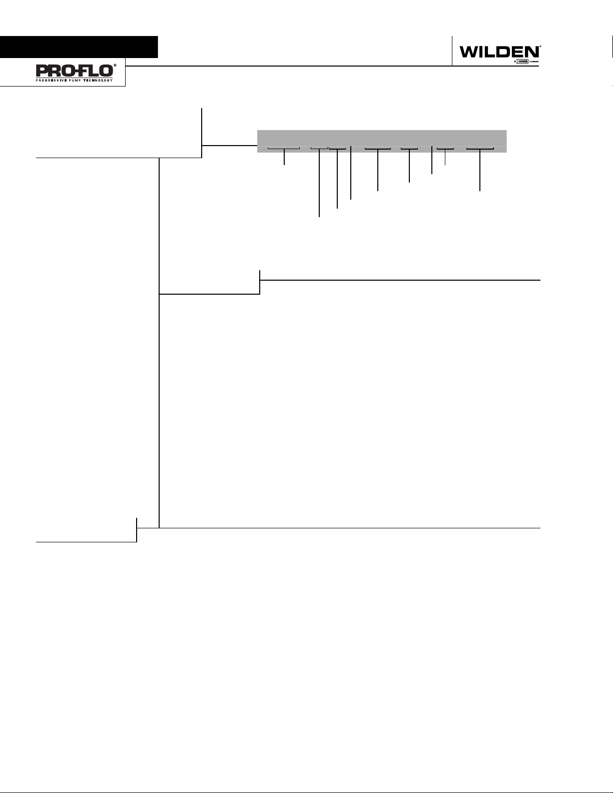
WILDEN PUMP DESIGNATION SYSTEM
P.025 ORIGINAL™
PLASTIC
6 mm (1/4") Pump
Maximum Flow Rate:
18.2 lpm (4.8 gpm)
LEGEND
MODEL
MATERIAL CODES
WETTED PARTS & OUTER PISTON
KK = PVDF / PVDF
KZ = PVDF / NO PISTON
PP = POLYPROPYLENE /
POLYPROPYLENE
PZ = POLYPROPYLENE /
NO PISTON
CENTER SECTION
LL = ACETAL
PP = POLYPROPYLENE
AIR VALVE
L = ACETAL
P = POLYPROPYLENE
P.025 / XXXXX / XXX / XX / XXX / XXXX
O-RINGS
DIAPHRAGMS
AIR VALVE
CENTER SECTION
WETTED PAR TS & OUTER PISTON
DIAPHRAGMS
BNS = BUNA-N (Red Dot)
TNL = PTFE W/ NEOPRENE
BACK-UP O-RING,
IPD (White)
WFS = WIL-FLEX™ [Santoprene®
(Orange Dot)]
VALVE BALL
TF = PTFE (White)
VALVE SEAT
VALVE BALL S
VALVE SEAT
K = PVDF
P = POLYPROPYLENE
VALVE SEAT O-RING
BN = BUNA-N (Red Dot)
TV = PTFE ENCAP. VITON
WF = WIL-FLEX™ [Santoprene®]
SPECIALTY
CODE
(if applicable)
®
SPECIALTY CODES
0502 PFA coated hardware
0512 Adapter block, no muffler, Pro-Flo
center section
Viton® is a registered trademark of Dupont Dow Elastomers.
WILDEN PUMP & ENGINEERING, LLC
®
,
2
WIL-10090-E-04
Section 3
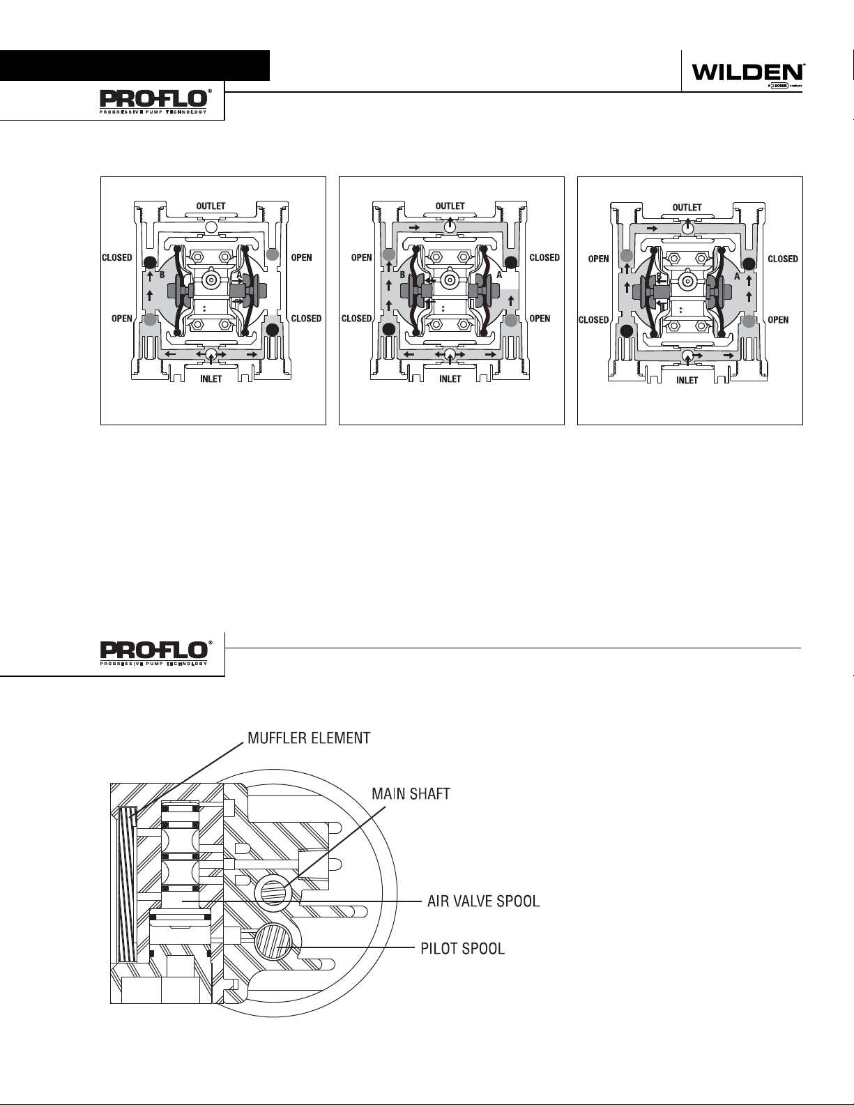
HOW IT WORKS
The Wilden diaphragm pump is an air-operated, positive displacement, self-priming pump. These drawings show fl ow pattern through
the pump upon its initial stroke. It is assumed the pump has no fl uid in it prior to its initial stroke.
RIGHT STROKE MID STROKE LEFT STROKE
FIGURE 1 The air valve directs pressurized air to the back
side of diaphragm A. The compressed air is applied directly
to the liquid column separated by elastomeric diaphragms.
The diaphragm acts as a separation membrane between the
compressed air and liquid, balancing the load and removing
mechanical stress from the diaphragm. The compressed
air moves the diaphragm away from the center block of
the pump. The opposite diaphragm is pulled in by the shaft
connected to the pressurized diaphragm. Diaphragm B is
on its suction stroke; air behind the diaphragm has been
forced out to the atmosphere through the exhaust port
of the pump. The movement of diaphragm B toward the
center block of the pump creates a vacuum within chamber
B. Atmospheric pressure forces fluid into the inlet manifold
forcing the inlet valve ball off its seat. Liquid is free to move
past the inlet valve ball and fill the liquid chamber (see
shaded area).
FIGURE 2 When the pressurized diaphragm, diaphragm
A, reaches the limit of its discharge stroke, the air valve
redirects pressurized air to the back side of diaphragm
B. The pressurized air forces diaphragm B away from the
center block while pulling diaphragm A to the center block.
Diaphragm B is now on its discharge stroke. Diaphragm B
forces the inlet valve ball onto its seat due to the hydraulic
forces developed in the liquid chamber and manifold of the
pump. These same hydraulic forces lift the discharge valve
ball off its seat, while the opposite discharge valve ball is
forced onto its seat, forcing fluid to flow through the pump
discharge. The movement of diaphragm A toward the center
block of the pump creates a vacuum within liquid chamber
A. Atmospheric pressure forces fluid into the inlet manifold
of the pump. The inlet valve ball is forced off its seat allowing
the fluid being pumped to fill the liquid chamber.
FIGURE 3 At completion of the stroke, the air valve again
redirects air to the back side of diaphragm A, which starts
diaphragm B on its exhaust stroke. As the pump reaches
its original starting point, each diaphragm has gone through
one exhaust and one discharge stroke. This constitutes
one complete pumping cycle. The pump may take several
cycles to completely prime depending on the conditions of
the application.
WIL-10090-E-04
HOW IT WORKS—AIR DISTRIBUTION SYSTEM
Figure 1
3
The Pro-Flo® patented air distribution system incorporates three moving parts: the
air valve spool, the pilot spool, and the
main shaft/diaphragm assembly. The heart
of the system is the air valve spool and
air valve. As shown in Figure 1, this valve
design incorporates an unbalanced spool.
The smaller end of the spool is pressurized
continuously, while the large end is alternately pressurized and exhausted to move
the spool. The spool directs pressurized
air to one chamber while exhausting the
other. The air causes the main shaft/
diaphragm assembly to shift to one side
— discharging liquid on one side and
pulling liquid in on the other side. When
the shaft reaches the end of its stroke, it
actuates the pilot spool, which pressurizes and exhausts the large end of the
air valve spool. The pump then changes
direction and the same process occurs in
the opposite direction, thus reciprocating
the pump.
WILDEN PUMP & ENGINEERING, LLC
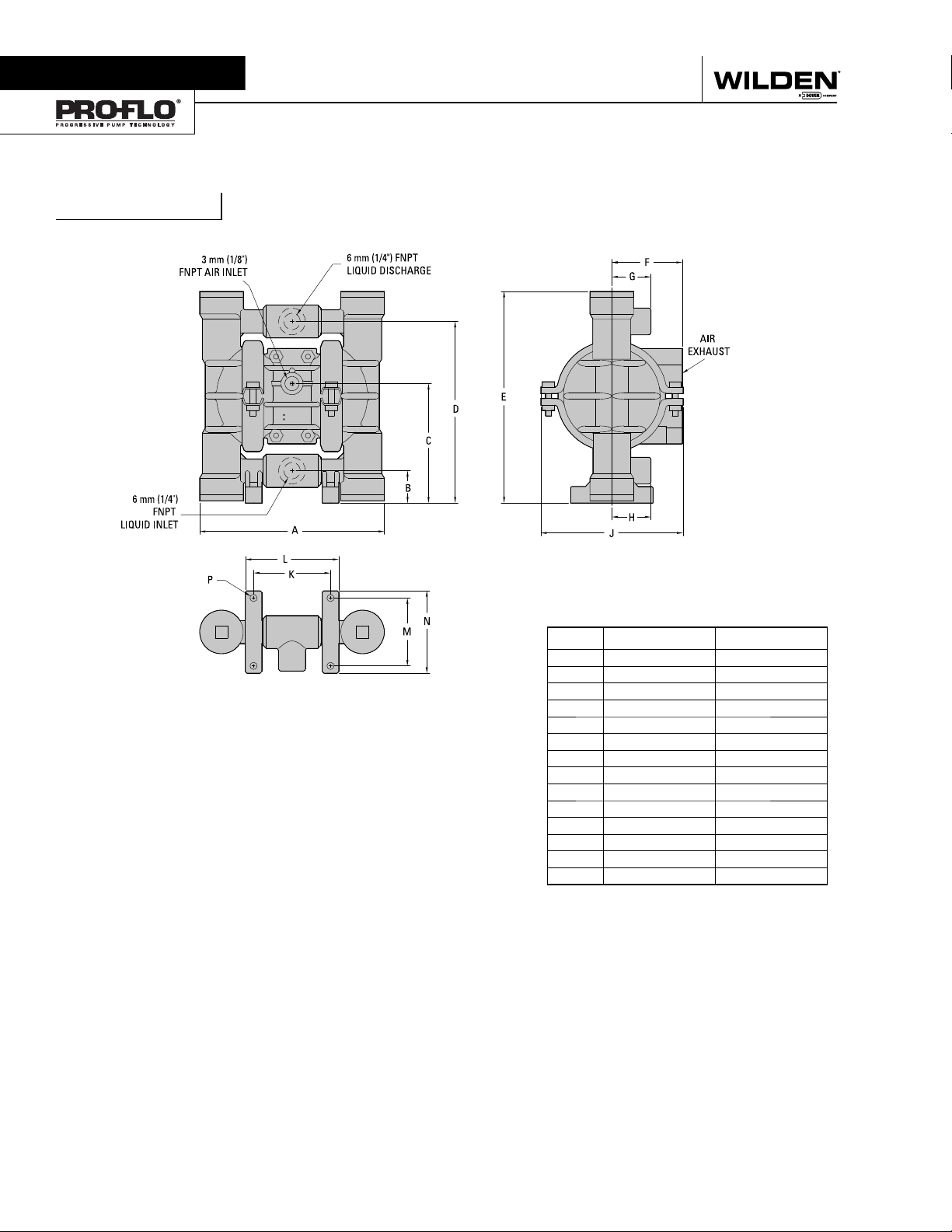
Section 4
P.025 M eta l
DIMENSIONAL DRAWINGS
DIMENSIONS
ITEM METRIC (mm) STANDARD (inch)
A 145 5.7
B 25 1.0
C 94 3.7
D 140 5.5
E 163 6.4
F 56 2.2
G 30 1.2
H 30 1.2
J 114 4.5
K 61 2.4
L 74 2.9
M 53 2.1
N 64 2.5
P Ø5 Ø.2
REV. B
WILDEN PUMP & ENGINEERING, LLC
4
WIL-10090-E-04
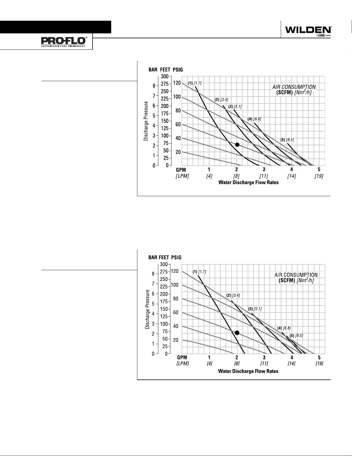
Section 5A
PERFORMANCE
P.025 PLASTIC
RUBBER-FITTED
Height ....................................163 mm (6.4")
Width .....................................145 mm (5.7")
Depth ....................................115 mm (4.5")
Est. Ship Weight .....
PVDF 1.4 kg (3 lbs)
Air Inlet ..................................... 3 mm (1/8")
Inlet .......................................... 6 mm (1/4")
Outlet ....................................... 6 mm (1/4")
Suction Lift ........................... 2.74 m Dry (9')
9.45 m Wet (31')
Displacement per
Stroke .........................0.02 l (0.004 gal.)
Max. Flow Rate ...............18.1 lpm (4.8 gpm)
Max. Size Solids .................. 0.4 mm (1/64")
1
Displacement per stroke was calculated at 4.8 bar
(70 psig) air inlet pressure against a 2 bar (30 psig)
head pressure.
Example: To pump 7.6 lpm (2 gpm) against
a discharge pressure head of 2 bar (30 psig)
requires 4.1 bar (60 psig) and 2.0 Nm
(1.2 scfm) air consumption. (See dot on
chart.)
Caution: Do not exceed 8.6 bar (125 psig) air
supply pressure.
Polypropylene 1.4 kg (3 lbs)
1
3
/h
Flow rates indicated on chart were determined by pumping water.
For optimum life and performance, pumps should be specified so that daily operation parameters
will fall in the center of the pump performance curve.
P.025 PLASTIC
TPE-FITTED
Height ....................................163 mm (6.4")
Width .....................................145 mm (5.7")
Depth ....................................115 mm (4.5")
Est. Ship Weight .....
PVDF 1.4 kg (3 lbs)
Air Inlet ..................................... 3 mm (1/8")
Inlet .......................................... 6 mm (1/4")
Outlet ....................................... 6 mm (1/4")
Suction Lift ......................... 3.05 m Dry (10')
8.84 m Wet (29')
Displacement per
Stroke ....................... 0.02 l gal. (0.005)
Max. Flow Rate ...............18.1 lpm (4.8 gpm)
Max. Size Solids .................. 0.4 mm (1/64")
1
Displacement per stroke was calculated at 4.8 bar
(70 psig) air inlet pressure against a 2 bar (30 psig)
head pressure.
Example: To pump 7.6 lpm (2 gpm) against
a discharge pressure head of 2 bar (30 psig)
requires 4.1 bar (60 psig) and 2.0 Nm
(1.2 scfm) air consumption. (See dot on
chart.)
Caution: Do not exceed 8.6 bar (125 psig) air
supply pressure.
Polypropylene 1.4 kg (3 lbs)
1
3
/h
Flow rates indicated on chart were determined by pumping water.
For optimum life and performance, pumps should be specified so that daily operation parameters
will fall in the center of the pump performance curve.
WIL-10090-E-04
5
WILDEN PUMP & ENGINEERING, LLC
 Loading...