

Wilden HS400S User Manual
EOM
Engineering
Operation &
Maintenance
HS400S
Advanced™ Metal Pump
Where Innovation Flows
wildenpump.com
USE
TABLE OF CONTENTS
SECTION 1 CAUTIONS—READ FIRST! ..............................................1
SECTION 2 WILDEN PUMP DESIGNATION SYSTEM ................................2
SECTION 3 HOW IT WORKS—PUMP & AIR DISTRIBUTION SYSTEM ................3
SECTION 4 DIMENSIONAL DRAWING ..............................................4
SECTION 5 PERFORMANCE
HS400S Performance
TPE-Fitted ..................................................... 5
Suction-Lift Curve ..................................................... 6
SECTION 6 SUGGESTED INSTALLATION, OPERATION & TROUBLESHOOTING ........7
SECTION 7 DISASSEMBLY / REASSEMBLY ........................................10
Air Valve / Center Section Disassembly ......................................15
Reassembly Hints & Tips ..................................................17
SECTION 8 EXPLODED VIEW & PARTS LISTING
HS400S Metal ...........................................................18
O
I
I
&
I
s
s
a
l
C
NON
U.S. Clean Air Act
Amendments of 1990
D
e
p
l
e
t
i
n
z
o
n
e
s
e
c
n
a
t
s
b
u
S
g
Section 1
CAUTIONS—READ FIRST!
CAUTION: Do not apply compressed air to the
exhaust port — pump will not function.
CAUTION: Do not over-lubricate air supply —
excess lub rication will reduce pump p erformance .
Pump is pre-lubed.
TEMPERATURE LIMITS:
Polypropylene 0°C to 79°C 32°F to 175°F
PVDF –12°C to 107°C 10°F to 225°F
PFA –7°C to 107°C 45°F to 225°F
Neoprene –18°C to 93°C 0°F to 200°F
Buna-N –12°C to 82°C 10°F to 180°F
EPDM –51°C to 138°C –60°F to 280°F
Viton
®
FKM –40°C to 177°C –40°F to 350°F
Wil-Flex™ –40°C to 107°C –40°F to 225°F
Saniflex™ –29°C to 104°C –20°F to 220°F
Polyurethane –12°C to 66°C 10°F to 150°F
Polytetrafluoroethylene (PTFE)1 4°C to 104°C 40°F to 220°F
Nordel
®
EPDM –51°C to 138°C –60°F to 280°F
Nylon –18°C to 93°C 0°F to 200°F
Acetal –29°C to 82°C –20°F to 180°F
SIPD PTFE
SIPD PTFE
Geolast
1
with Neoprene-backed
with
EPDM-backed 4°C to 137°C 40°F to 280°F
®
–40°C to 82°C –40°F to 180°F
4°C to 149°C (40°F to 300°F) - 13 mm (1/2") and 25 mm (1") models only.
4°C to 93°C 40°F to 200°F
NOTE: Not all materials are available for all
models. Refer to Section 2 for the material
options available for your pump.
CAUTION: The process fluid and cleaning fluids
must be chemically compatible with all wetted
pump components. Consult Chemical Resistance
Guide.
CAUTION: Do not exceed 82°C (180°F) air inlet
temperature for Pro-Flo® SHIFT models.
CAUTION: Pumps should be thoroughly flushed
before installing into process lines. FDA- and
USDA-approved pumps should be cleaned and /
or sanitized before being used.
CAUTION: Always wear safety glasses when
operating pump. If diaphragm rupture occurs,
material being pumped may be forced out air
exhaust.
CAUTION: Before any maintenance or repair is
attempted, the compressed air line to the pump
should be disconnected and all air pressure
allowed to bleed from pump. Disconnect all
intake, discharge and air lines. Drain the pump
by allowing any fluid to flow into a suitable
container.
CAUTION: Blow out air line for 10 to 20 seconds
before attaching to pump to make sure all pipeline
debris is clear. Use an in-line air filter. A 5μ (micron)
air filter is recommended.
CAUTION: When choosing pump materials, be
sure to check the temperature limits for all wetted
components. Example: Viton® has a maximum
limit of 177°C (350°F), but polypropylene has a
maximum limit of only 79°C (175°F).
CAUTION: Maximum temperature limits are
based upon mechanical stress only. Certain
chemicals will significantly reduce maximum
safe operating temperatures. Consult Chemical
Resistance Guide for chemical compatibility and
temperature limits.
WARNING : Prevent static sparking — If static
sparking occurs, fire or explosion could result.
Pump, valves and containers must be grounded
to a proper grounding point when handling
flammable fluids and whenever discharge of
static electricity is a hazard.
CAUTION: Do not exceed 8.6 bar (125 psig) air
supply pressure.
NOTE: Before starting disassembly, mark a line
from each liquid chamber to its corresponding air
chamber. This line will assist in proper alignment
during reassembly.
CAUTION: Pro-Flo® SHIFT is available in
both single-point exhaust (submersible) and
standard (non-submersible) options. Do not use
standard Pro-Flo® SHIFT models in submersible
applications. Turbo-Flo™ pumps are also
available in a single-point exhaust (submersible)
configuration.
CAUTION : Tighten all hardware prior to installation.
WIL-11112- E- 01 1 WILDEN PUMP & ENGINEERING, LLC

Section 2
WILDEN PUMP DESIGNATION SYSTEM
HS400S METAL
38 mm (1-1/2”) Pump
Maximum Flow Rate:
227 lpm (60 gpm)
LEGEND
XHS400S / XXX XX / X XX / XX / XXX / XXXX
MODEL
MATERIAL CODES
MODEL
XHS400S= HIGH PRESSURE SIMPLEX/
WETTED PARTS
AND OUTER PISTON
AS = ALUMINUM / STAINLESS STEEL
AIR CHAMBERS
A = ALUMINUM
ATEX
DIAPHRAGMS
VALVE BALLS
AIR VALVE
CENTER BLOCK
AIR CHAMBERS
OUTER PISTON
WETTED PARTS
CENTER BLOCK
A = ALUMINUM
AIR VALVE
A = ALUMINUM
DIAPHRAGMS
FWS = SANITARY WIL-FLEX
[Santoprene® (Two Orange
Dots)]
™
O-RINGS
VALVE SEAT
SPECIALTY
CODE
(if applicable)
VALVE BALLS
WF = WIL-FLEX
[Santoprene® (Orange Dot)]
VALVE SEAT
A = ALUMINUM
VALVE SEAT O-RINGS
TF = PTFE (White)
™
SPECIALTY CODES
0320 Single-Point Exhaust
0504 DIN flange
NOTE: MOST ELASTOMERIC MATERIALS USE COLORED DOT FOR IDENTIFICATION.
WILDEN PUMP & ENGINEERING, LLC 2 WIL-11112- E- 01
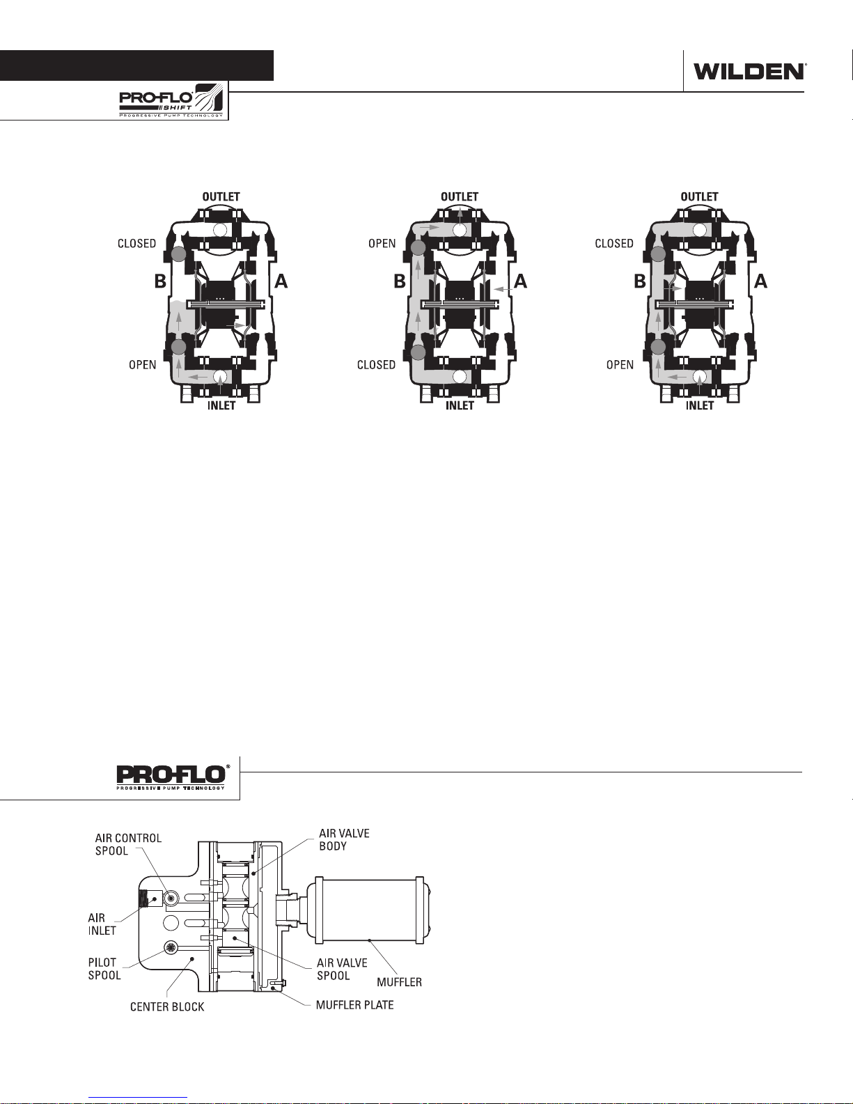
Section 3
HOW IT WORKS—PUMP
The Wilden diaphragm pump is an air-operated, positive displacement, self-priming pump. These drawings show flow pattern
through the pump upon its initial stroke. It is assumed the pump has no fluid in it prior to its initial stroke.
FIGURE 1 When air pre ssure is supplied
to the pum p, the air valve dir ects pr essure
to the back side of the diaphragm A. The
compressed air moves the diaphragm
away from the center section of the
pump. The opposite diaphragm is
pulled in by the shaft connected to the
pressurized diaphragm. Diaphragm
B is on its suction stroke; air behind
the diaphragm has been forced out to
the atmosphere through the exhaust
port. The movement of diaphragm B
towards the center section of the pump
creates a vacuum within the chamber B.
Atmospheric pressure forces fluid into
the inlet manifold forcing the inlet valve
ball off of its seat. Liquid is free to move
past the inlet valve ball and fill the liquid
chamber (see shaded area).
HOW IT WORKS—AIR DISTRIBUTION SYSTEM
FIGURE 2 Once the shaft has reached
the end of its stroke, the air valve redirects
pressurized air to the back side of the
diaphragm B. This pressurized air is
also directed to the opposite side of the
diaphragm A through a passageway that
is routed through the common shaft and
outer piston. The pressurized air forces
diaphragm B away from the center
section while also pushing diaphragm
A to the center section. Diaphragm B is
now on its discharge stroke. Diaphragm B
forces the inlet valve ball onto its seat due
to the hydraulic forces developed in the
liquid chamber and manifold of the pump.
These same hydraulic forces lift the
discharge valve ball of f of its seat, forcing
fluid to flow through the pump discharge.
The pressure on diaphragm A creates a
force on the shaft that is combined with
the pressure from diaphragm B. This total
load is transferred to the liquid creating a
liquid pressure that is two times greater
than the supplied air pressure.
The heart of the patented Pro-Flo® SHIFT Air Distribution System
(ADS) is the air valve assembly. The air valve design incorporates
an unbalanced spool with the small end of the spool being
pressurized continuously while the large end of the spool is
alternately pressurized, then exhausted to move the spool. The
air valve spool directs pressurized air to one chamber while
exhausting the other. The air forces the main shaf t /diaphragm
assembly to move to one side – discharging liquid on that side
and pulling liquid in on the other side. When the shaf t reaches
the end of the stroke, the inner piston ac tuates the pilot spool,
which controls the air to the large end of the air valve spool. The
repositioning of the air valve spool routes the air to the other air
chamber. The air control spool allows air to flow freely into the air
chamber for the majority of each pump stroke, but it significantly
restricts the flow of air into the air chamber when activated by the
inner piston near the end of the each stroke.
FIGURE 3 At completion of the stroke,
the air valve again redirects air to the
back side of the diaphragm A, which
star ts diaphragm B on its exhaust s troke.
As the pump reaches its original starting
point, each diaphragm has gone through
one exhaust and one discharge stroke.
This constitutes one complete pumping
cycle. The pump may take several cycles
to completely prime depending on the
condition of the application.
WIL-11112- E- 01 3 WILDEN PUMP & ENGINEERING, LLC
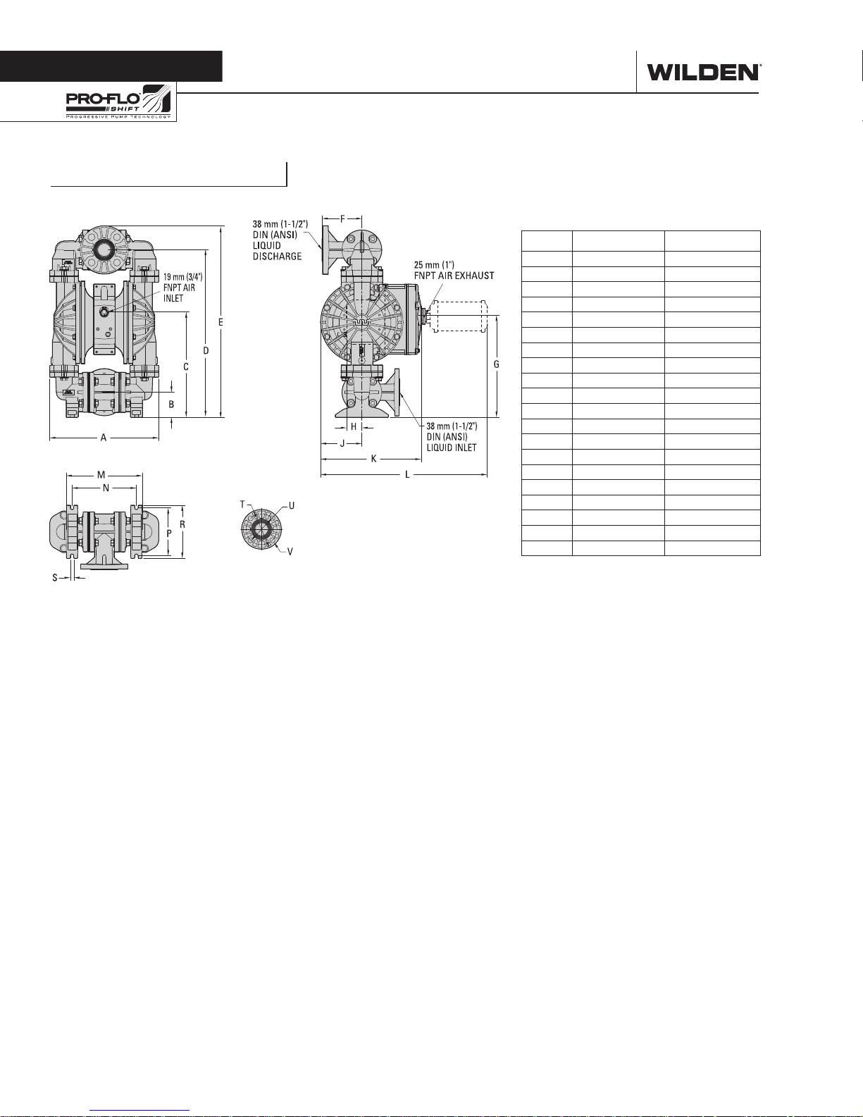
Section 4
DIMENSIONAL DRAWINGS
HS400S ALUMINUM
DIMENSIONS
ITEM METRIC (mm) STANDARD (inch)
A 343 13.5
B 79 3.1
C 335 13.2
D 531 20.9
E 605 23.8
F 122 4.8
G 325 12.8
H 48 1.9
J 132 5.2
K 320 12.6
L 531 20.9
M 244 9.6
N 206 8.1
P 152 6.0
R 170 6.7
S 10 0.4
DIN (mm) ANSI (inch)
T 150 DIA. 5.0 DIA.
U 110 DIA. 3.9 DIA.
V 18 DIA. 0.6 DIA.
LW0287 REV. A
WILDEN PUMP & ENGINEERING, LLC 4 WIL-11112- E- 01
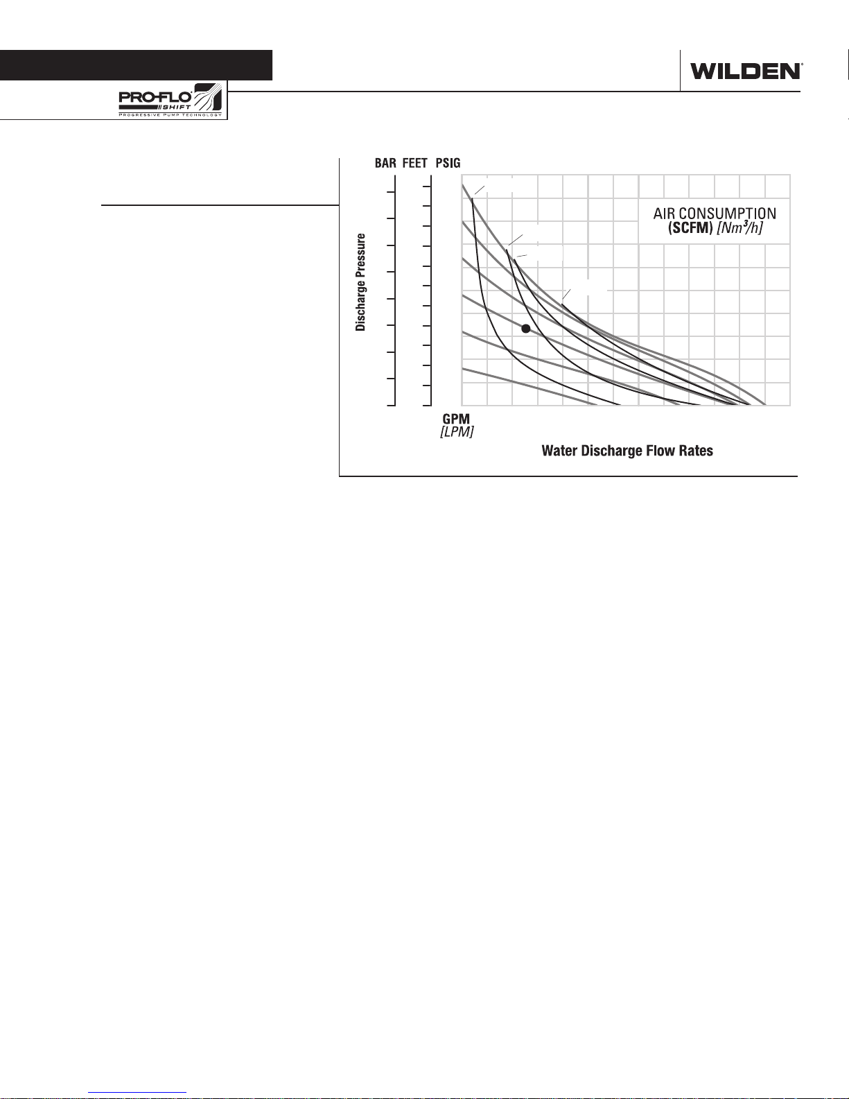
Section 5
PERFORMANCE
HS400S ALUMIMUM
TPE-FITTED
Height ................................. 605 mm (23.8")
Width .................................. 343 mm (13.5")
Depth .................................. 320 mm (12.6")
Ship Weight ............................27 kg (60 lbs)
Air Inlet ................................... 19 mm (3/4”)
Inlet ...................................... 38 mm (1-1/2")
Outlet ................................... 38 mm (1-1/2")
Suction Lift ..........................1.1 m Dry (3.6')
9.0 m Wet (29.5')
Disp. per Stroke ............... 0.26 L (0.07 gal)¹
Max. Flow Rate .............. 227 lpm (60 gpm)
Max. Size Solids .................. 8.0 mm (5/16")
1
Displacement per stroke was calculated at
4.8 bar (70 psig) air inlet pressure against a
2.1 bar (30 psig) head pressure.
Example: To pump 45 lpm (12 gpm) against
a discharge head of 4.8 bar (70 psig) requires
4.1 bar (60 psig) and 59 Nm3/h (35 scfm) air
consumption.
Caution: Do not exceed 8.6 bar (125 psig)
air supply pressure.
250
120
20[34]
200
150
psig
100
psig
80
psig
60
psig
40[68]
60[102]
80[136]
16
14
12
10
500
400
300
8
100
6
200
4
100
2
50
40
psig
20
psig
00
10 20 30 40 50 60
Flow rates indicated on chart were determined by pumping water.
For optimum life and performance, pumps should be specified so that daily operation
parameters will fall in the center of the pump's performance curve.
[38] [76] [114] [151] [189] [227]
WIL-11112- E- 01 5 WILDEN PUMP & ENGINEERING, LLC
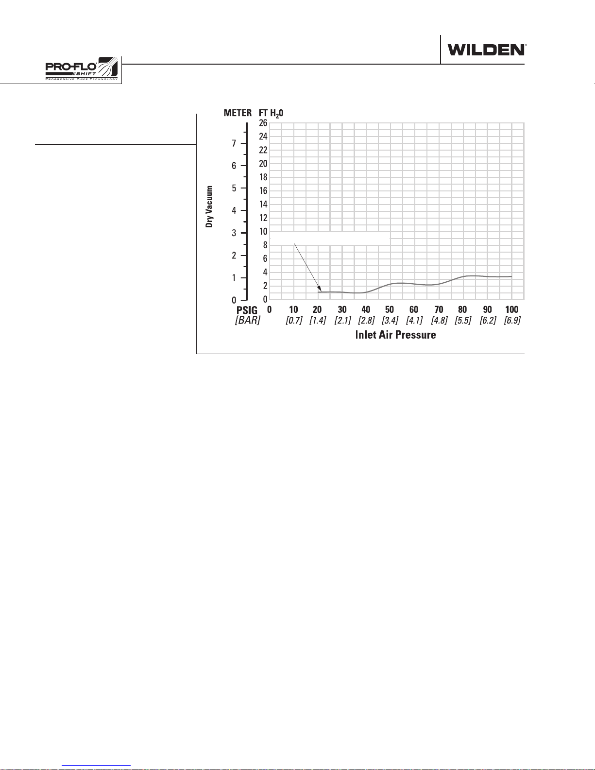
SUCTION—LIFT CURVES
HS400S ALUMIUM
SUCTION-LIFT CAPABILITY
Aluminum Wetted Path (HS400S)
Suction-lift curves are calibrated for pumps operating
at 305 m (1,000') above sea level. This chart is meant
to be a guide only. There are many variables that can
affect your pump’s operating characteristics. The
number of intake and discharge elbows, viscosity of
pumping fluid, elevation (atmospheric pressure) and
pipe friction loss all affect the amount of suction lift
your pump will attain.
WILDEN PUMP & ENGINEERING, LLC 6 WIL-11112- E- 01
 Loading...