

Wilden H800 Operation & Maintenance Manual
EOM
Engineering
Operation &
Maintenance
H800
Advanced
Metal Pump
™
Series
Where Innovation Flows
www.wildenpump.com
REPLACES WI L-11150 -E -0 9
WI L-11150 -E -10

TABLE OF CONTENTS
SECTION 1 CAUTIONS—READ FIRST! ..............................................1
SECTION 2 WILDEN PUMP DESIGNATION SYSTEM .................................2
SECTION 3 HOW IT WORKS—PUMP & AIR DISTRIBUTION SYSTEM ................3
SECTION 4 DIMENSIONAL DRAWINGS .............................................4
SECTION 5 PERFORMANCE ........................................................5
SECTION 6 SUGGESTED INSTALLATION, OPERATION & TROUBLESHOOTING ........6
SECTION 7 ASSEMBLY / DISASSEMBLY ............................................9
SECTION 8 EXPLODED VIEW & PARTS LISTING
H800 Metal - Ductile Iron .............................................18
H800 Metal - Stainless Steel ...........................................19
Center Section ......................................................20
SECTION 9 ELASTOMER OPTIONS .................................................22
Section 1
CAUTIONS—READ FIRST!
TEMPERATURE LIMITS:
Neoprene –17.7°C to 93.3°C 0°F to 200°F
Buna-N –12.2°C to 82.2°C 10°F to 180°F
Nordel
Viton® –40°C to 176.7°C –40°F to 350°F
Saniflex™ –28.9°C to 104.4°C –20°F to 220°F
Wil-Flex™ -40ºC to 107.2ºC –40ºF to 225ºF
Polytetrafluoroethylene (PTFE)
4.4°C to 104.4°C 40°F to 220°F
Polyurethane –12.2°C to 65.6°C 10°F to 150°F
NOTE: Not all materials are available for all
models. Refer to Section 2 for material options
for your pump.
CAUTION: When choosing pump materials, be
sure to check the temperature limits for all wetted
components. Example: Viton® has a maximum
limit of 177°C (350°F) but polypropylene has a
maximum limit of only 79°C (175°F).
CAUTION: Maximum temperature limits are
based upon mechanical stress only. Certain
chemicals will significantly reduce maximum
safe operating temperatures. Consult Chemical
Resistance Guide for chemical compatibility and
temperature limits.
WARNING: Prevent static sparking — If static
sparking occurs, fire or explosion could result.
Pump, valve and containers must be grounded
to a proper grounding point when handling
flammable fluids and whenever discharge of
static electricity is a hazard.
®
–51.1°C to 137.8°C –60°F to 280°F
CAUTION: Always wear safety glasses when
operating pump. If diaphragm rupture occurs,
material being pumped may be forced out air
exhaust.
CAUTION: Before any maintenance or repair is
attempted, the compressed air line to the pump
should be disconnected and all air pressure
allowed to bleed from pump. Disconnect all
intake, discharge and air lines. Drain the pump
by turning it upside down and allowing any fluid
to flow into a suitable container.
CAUTION: Blow out air line for 10 to 20 seconds
before attaching to pump to make sure all pipeline
debris is clear. Use an in-line air filter. A 5μ (micron)
air filter is recommended.
NOTE: Before starting disassembly, mark a line
from each liquid chamber to its corresponding air
chamber. This line will assist in proper alignment
during reassembly.
CAUTION: Wilden H800 High Pressure pumps
cannot be used in submersible applications.
CAUTION: Tighten all hardware prior to installation.
CAUTION: Do not exceed 5.9 bar (85 psig) air
supply pressure.
CAUTION: All piping, valves, gauges and other
components installed on the liquid discharge must
have a minimum pressure rating of 20.7 bar (300 psig).
CAUTION: The discharge pressure generated by
this pump is 3X the inlet pressure supplied.
CAUTION: The process fluid and cleaning fluids
must be chemically compatible with all wetted
pump components. Consult Chemical Resistance
Guide.
CAUTION: Pumps should be thoroughly flushed
before installing into process lines. FDA- and
USDA- approved pumps should be cleaned and /
or sanitized before being used.
WIL-1115 0 - E-10
1
WILDEN PUMP & ENGINEERING, LLC
Section 2
WILDEN PUMP DESIGNATION SYSTEM
H800 METAL
51 mm (2") Pump
Maximum Flow Rate:
360 lpm (95 gpm)
LEGEND
MATERIAL CODES
MODEL
H800 = 51 mm (2" ) HIGH
PRESSURE
WETTED PARTS
& OUTER PISTON
SS = STAINLESS STEEL/
STAINLESS STEEL
WW = DUCTILE IRON/
DUCTILE IRON
AIR CHAMBERS
S = S TAINLESS STEEL
W = DUCTILE IRON
H800 / X X X X X / XXX / XX / X XX / XXXX
MODEL
CENTER BLOCK
AIR CHAMBERS
WETTED PARTS & OUTER PISTON
CENTER BLOCK
A = ALUMINUM
AIR VALVE
A = ALUMINUM
DIAPHRAGMS
FWL = FUL L-STROKE
SANITARY
WIL-FLE X™ IPD
FWS = SANITARY
WIL-FLE X ™
TWS = FULL-STROKE PTFE
W/WIL-FLEX™
BACKUP
DIAPHRAGMS
VALVE BALLS
AIR VALVE
1
1
O-RINGS
VALVE SEAT
VALVE BALL
TF = PTFE (WHITE)
WF = WIL-FLEX™
VALVE SEAT
S = S TAINLESS STEEL
M = MILD STEEL
VALVE SEAT O-RING
TF = PT FE (WHITE)
WF = WIL-FLEX™
SPECIA LTY
CODE
(if applicable)
[SANTOPRENE
(ORANGE DOT)]
[SANTOPRENE
(ORANGE DOT)]
®
®
Notes: 1 Meets Requirement s of FDA CFR21.177
SPECIALTY CODES
0504 DIN flange
NOTE: MOST EL ASTOMERIC MATERIALS USE COLORED DOTS FOR IDENTIFICATION.
NOTE: Not all models are available with all material options.
WILDEN PUMP & ENGINEERING, LLC
2
WIL-1115 0 - E-10
Section 3
HOW IT WORKS—PUMP
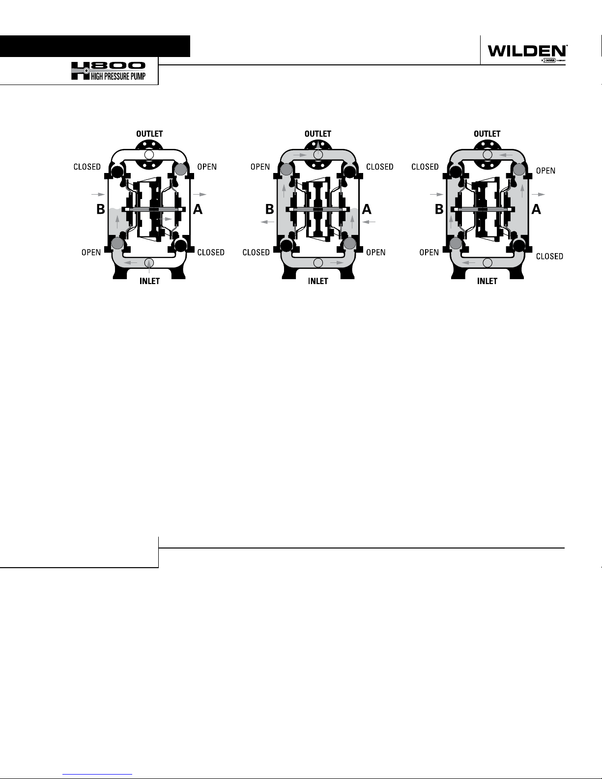
The Wilden diaphragm pump is an air-operated, positive displacement, self-priming pump. These drawings show flow pattern
through the pump upon its initial stroke. It is assumed the pump has no fluid in it prior to its initial stroke.
FIGURE 1 When air pressure is supplied
to the pump, the air valve directs pressure
to the back side of diaphragm A. The
compressed air moves the diaphragm
away from the center section of the pump.
The opposite diaphragm is pulled in by
the shaft connected to the pressurized
diaphragm. Diaphragm B is on its suction
stroke; air behind the diaphragm has been
forced out to the atmosphere through
the exhaust port. The movement of
diaphragm B towards the center section
of the pump creates a vacuum within
chamber B. Atmospheric pressure forces
fluid into the inlet manifold forcing the
inlet valve ball off of its seat. Liquid is free
to move past the inlet valve ball and fill
the liquid chamber (see shaded area).
FIGURE 2 Once the shaft has reached the
end of its stroke, the air valve redirects
pressurized air to the back side of
diaphragm B.
FIGURE 3 At completion of the stroke,
the air valve again redirects air to the
back side of diaphragm A, which star ts
diaphragm B on its exhaust stroke. As
the pump reaches its original star ting
point, each diaphragm has gone through
one exhaust and one discharge stroke.
This constitutes one complete pumping
cycle. The pump may take several cycles
to completely prime depending on the
condition of the application.
HOW IT WORKS—THE POWER PRINCIPLE
The H800 uses an integral power amplifier piston together with two diaphragms to yield a pressure ratio of 3:1 (e.g. 85 psig air
inlet will develop pump discharge pressures up to 250 psig). Air is simultaneously directed behind the amplifier piston as well as
one of the diaphragms via specialized air manifold porting. The sum of the two sur face areas is three times that of the diaphragm.
Therefore, the discharge is amplified by a 3:1 pressure output ratio.
WIL-1115 0 - E-10
3
WILDEN PUMP & ENGINEERING, LLC
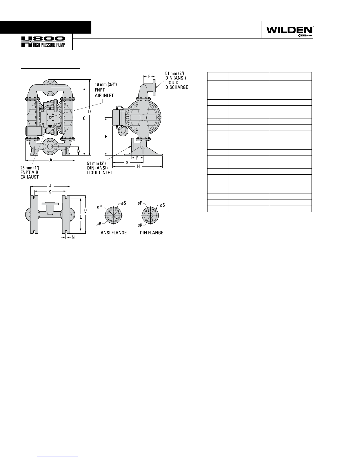
Section 4
DIMENSIONAL DRAWINGS
H800 Metal
DIMENSIONS
ITEM Metric (mm) Standard (inch)
A 490 19.3
B 89 3.5
C 677 26.7
D 760 29.9
E 378 14.9
F 120 4.7
G 307 12.1
H 498 19.6
J 394 15.5
K 318 12.5
L 325 12.8
M 379 14.9
N 14 0.6
DIN FLANGE
P 125 DIA. 4.9 DIA.
R 165 DIA. 6.5 DIA.
S 18 DIA. 0.7 DIA.
ANSI FLANGE
P 125 DIA. 5.0 DIA.
R 165 DIA. 6.5 DIA.
S 19 DIA. 0.8 DIA.
REV B
WILDEN PUMP & ENGINEERING, LLC
4
WIL-1115 0 - E-10
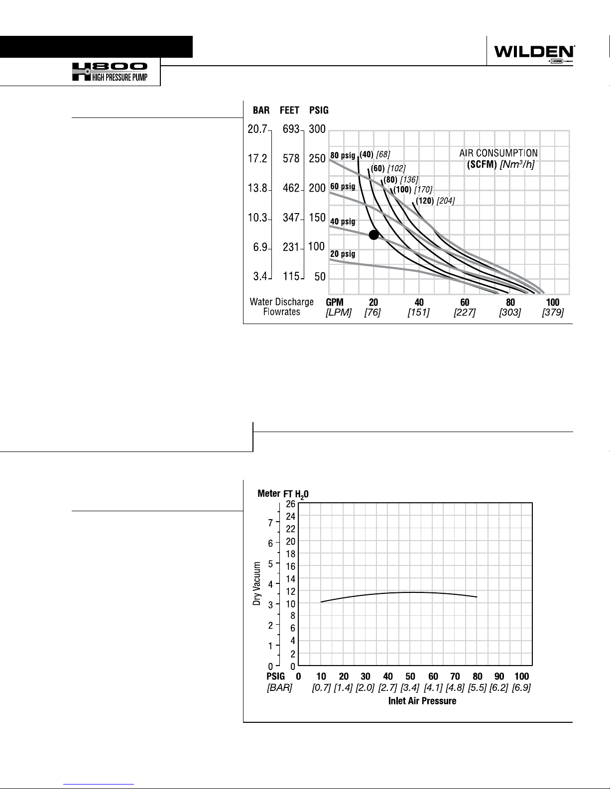
Section 5
H800 High Pressure Suction Lift Capability
PERFORMANCE (TPE/FULL STROKE PTFE)
A. P400 Aluminum performance
Curves
H800 METAL
Height………………… . ……759 mm (29.9")
Width ...................................490 mm (19.3")
Depth ...................................546 mm (21.5")
Est. Ship Weight ...... Stainless Steel 128 kg (283 lb)
Ductile Iron 128 kg (283 lb)
Air Inlet ....................................19 mm (3/4")
Inlet ........................................... 51 mm (2")
Outlet ........................................ 51 mm (2")
Suction Lift ...................... 3.7 m Dry (12.0')
9.0 m Wet (29.5')
Displacement Per Stroke ...1.67 L (0.44 gal)
Max. Flow Rate .............. 360 lpm (95 gpm)
Max. Size Solids .................. 12.7 mm (1/2")
1
Displacement per stroke was calculated at
4.8 bar (70 psig) air inlet pressure against a
5.1 bar (75 psig) head pressure.
Example: To pump 76 lpm (20 gpm)
against a discharge pressure head of 8.6
bar (125 psig) requires 2.9 bar (42 psig)
and 65 Nm3/h (38 scfm) air consumption.
Caution: Do not exceed 5.9 bar (85 psig) air
supply pressure.
Flow rates indicated on chart were determined by pumping water.
For optimum life and performance, pumps should be specified so that daily operation
parameters will fall in the center of the pump's performance curve.
SUCTION-LIFT CURVE
H800 METAL HIGH PRESSURE
SUCTION-LIFT CAPABILITIES
Suction lift curves are calibrated for
pumps operating at 305 m (1,000')
above sea level. This chart is meant
to be a guide only. There are many
variables that can affect your pump’s
operating characteristics. The number of
intake and discharge elbows, viscosity
of pumping fluid, elevation (atmospheric
pressure) and pipe friction loss all affect
the amount of suction lift your pump will
attain.
WIL-1115 0 - E-10
5
WILDEN PUMP & ENGINEERING, LLC

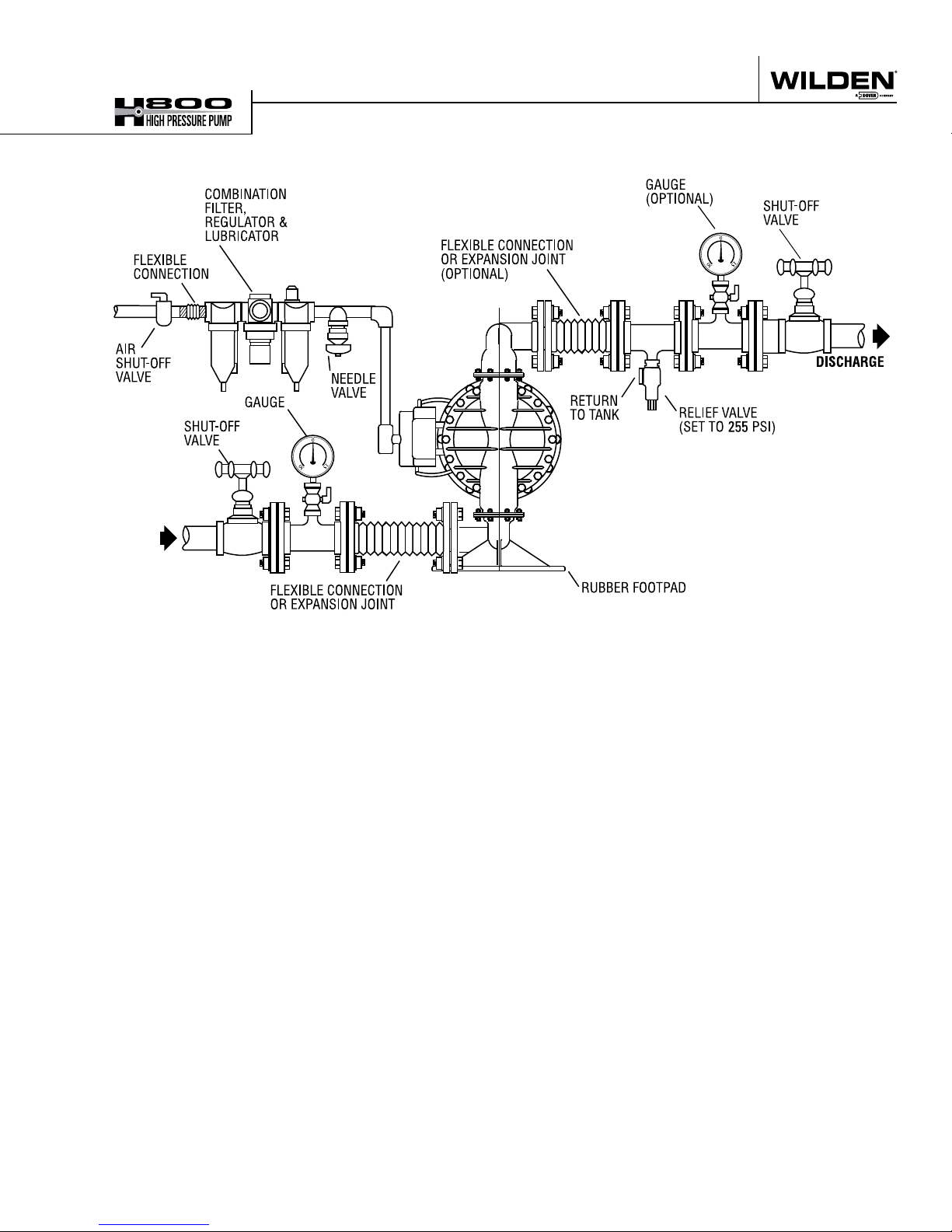
Section 6
SUGGESTED INSTALLATION
Wilden pumps are designed to meet the performance
requirements of even the most demanding pumping
applications. They have been designed and manufactured
to the highest standards and are available in a variety of
liquid path materials to meet your chemical resistance
needs. Refer to the performance section of this manual for
an in-depth analysis of the performance characteristics of
your pump. Wilden offers the widest variety of elastomer
options in the industry to satisfy temperature, chemical
compatibility, abrasion resistance and flex concerns.
The suction pipe size should be at least the equivalent or
larger than the diameter size of the suction inlet on your
Wilden pump. The suction hose must be non-collapsible,
reinforced type as these pumps are capable of pulling a high
vacuum. Discharge piping should also be the equivalent
or larger than the diameter of the pump discharge, which
will help reduce friction losses. It is critical that all fittings
and connections are airtight or a reduction or loss of pump
suction capability will result.
INSTALLATION: Months of careful planning, study
and selection efforts can result in unsatisfactory pump
performance if installation details are left to chance.
Premature failure and long-term dissatisfaction can be
avoided if reasonable care is exercised throughout the
installation process.
LOCATION: Noise, safety and other logistical factors usually
dictate where equipment will be situated on the production
floor. Multiple installations with conflicting requirements
can result in congestion of utility areas, leaving few choices
for additional pumps.
Within the framework of these and other existing conditions,
every pump should be located in such a way that six key
factors are balanced against each other to maximum
advantage.
ACCESS: First of all, the location should be accessible. If
it’s easy to reach the pump, maintenance personnel will
have an easier time carrying out routine inspections and
adjustments. Should major repairs become necessary, ease
of access can play a key role in speeding the repair process
and reducing total downtime.
AIR SUPPLY: Every pump location should have an air line
large enough to supply the volume of air necessary to
achieve the desired pumping rate. Use air pressure up to
a maximum of 5.9 bar (85 psig) depending on pumping
requirements.
For best results, the pumps should use a 5μ (micron) air
filter, needle valve and regulator. The use of an air filter
before the pump will ensure that the majority of any pipeline
contaminants will be eliminated.
SOLENOID OPERATION: When operation is controlled by a
solenoid valve in the air line, three-way valves should be
used. This valve allows trapped air between the valve and the
pump to bleed off, after which improves pump performance.
Pumping volume can be estimated by counting the number
of strokes per minute and then multiplying the figure by the
displacement per stroke.
MUFFLER: Sound levels are reduced below OSHA
specifications using the standard Wilden muffler. Other
mufflers can be used to further reduce sound levels, but
they usually reduce pump performance.
ELEVATION: Selecting a site that is well within the pump’s
dynamic lift capability will assure that loss-of-prime issues will
be eliminated. In addition, pump efficiency can be adversely
affected if proper attention is not given to site location.
PIPING: Final determination of the pump site should not be
made until the piping challenges of each possible location
have been evaluated. The impact of current and future
installations should be considered ahead of time to make
sure that inadvertent restrictions are not created for any
remaining sites.
The best choice possible will be a site involving the
shortest and straightest hook-up of suction and discharge
piping. Unnecessary elbows, bends and fittings should
be avoided. Pipe sizes should be selected to keep friction
losses within practical limits. All piping should be supported
independently of the pump. In addition, the piping should
be aligned to avoid placing stress on the pump fittings.
Flexible hose can be installed to aid in absorbing the forces
created by the natural reciprocating action of the pump. If the
pump is to be bolted down to a solid location, a mounting
pad placed between the pump and the foundation will assist
in minimizing pump vibration. Flexible connections between
the pump and rigid piping will also assist in minimizing
pump vibration. If quick-closing valves are installed at any
point in the discharge system, or if pulsation within a system
becomes a problem, a surge suppressor (SD Equalizer
should be installed to protect the pump, piping and gauges
from surges and water hammer.
If the pump is to be used in a self-priming application, make
sure that all connections are airtight and that the suction lift is
within the model’s ability. Note: Materials of construction and
elastomer material have an effect on suction lift parameters.
Please refer to the performance section for specifics.
When pumps are installed in applications involving flooded
suction or suction head pressures, a gate valve should be
installed in the suction line to permit closing of the line for
pump service.
Pumps in service with a positive suction head are most efficient
when inlet pressure is limited to 0.5–0.7 bar (7–10 psig).
Premature diaphragm failure may occur if positive suction
is 0.7 bar (10 psig) and higher.
ALL WILDEN PUMPS ARE CAPABLE OF PASSING SOLIDS.
A STRAINER SHOULD BE USED ON THE PUMP INTAKE TO
ENSURE THAT THE PUMP'S RATED SOLIDS CAPACITY IS
NOT EXCEEDED.
CAUTION: DO NOT EXCEED 5.9 BAR (85 PSIG) AIR SUPPLY
PRESSURE.
®
)
WILDEN PUMP & ENGINEERING, LLC
6
WIL-1115 0 - E-10
SUGGESTED INSTALLATION
NOTE: In the event of a power failure, the shut-off
valve should be closed, if the restarting of the pump is
not desirable once power is regained.
AIR-OPERATED PUMPS: To stop the pump from
operating in an emergency situation, simply close
the shut-off valve (user-supplied) installed in the air
supply line. A properly functioning valve will stop the
air supply to the pump, therefore stopping output. This
shut-off valve should be located far enough away from
the pumping equipment such that it can be reached
safely in an emergency situation.
WIL-1115 0 - E-10
7
WILDEN PUMP & ENGINEERING, LLC
 Loading...