

Wilden H200 Advanced Metal Operation
EOM
Engineering
Operation &
Maintenance
H220 High-Pressure
FIT Metal Pump
Where Innovation Flows
wildenpump.com

TABLE OF CONTENTS
SECTION 1 CAUTIONS—READ FIRST! ..............................................1
SECTION 2 WILDEN PUMP DESIGNATION SYSTEM .................................2
SECTION 3 HOW IT WORKS—PUMP ................................................3
SECTION 4 DIMENSIONAL DRAWINGS .............................................4
SECTION 5 PERFORMANCE
H220 Metal TPE/Full-Stroke PTFE-Fitted .......................................5
Suction-Lift Curve .........................................................5
SECTION 6 SUGGESTED INSTALLATION, OPERATION & TROUBLESHOOTING ........6
SECTION 7 DISASSEMBLY / REASSEMBLY .........................................9
Reassembly Hints & Tips ..................................................14
SECTION 8 EXPLODED VIEW & PARTS LISTING
H220 Metal Wetted Path ...................................................16
H220 Metal Center Section ................................................18
SECTION 9 ELASTOMER OPTIONS .................................................20
Section 1
CAUTIONS—READ FIRST!
TEMPERATURE LIMITS:
Acetal –29°C to 82°C –20°F to 180°F
Buna-N –12°C to 82°C 10°F to 180°F
Geolast® –40°C to 82°C –40°F to 180°F
Neoprene –18°C to 93°C 0°F to 200°F
Nordel® EPDM –51°C to 138°C –60°F to 280°F
Nylon –18°C to 93°C 0°F to 200°F
PFA –7°C to 107°C 45°F to 225°F
Polypropylene 0°C to 79°C 32°F to 175°F
Polyurethane –12°C to 66°C 10°F to 150°F
PVDF –12°C to 107°C 10°F to 225°F
Saniflex™ –29°C to 104°C –20°F to 220°F
SIPD PTFE with EPDM-backed
SIPD PTFE with Neoprene-backed
PTFE
1
4°C to 104°C 40°F to 220°F
4°C to 137°C 40°F to 280°F
4°C to 93°C 40°F to 200°F
Viton® FKM –40°C to 177°C –40°F to 350°F
Wil-Flex™ –40°C to 107°C –40°F to 225°F
1
4°C to 149°C (40°F to 300°F) - 13 mm (1/2") and 25 mm (1") models only.
NOTE: Not all materials are available for all
models. Refer to Section 2 for material options
for your pump.
CAUTION: When choosing pump materials, be
sure to check the temperature limits for all wetted
components. Example: Viton® has a maximum
limit of 177°C (350°F) but polypropylene has a
maximum limit of only 79°C (175°F).
CAUTION : Maximum temperature limits are
based upon mechanical stress only. Certain
chemicals will significantly reduce maximum
safe operating temperatures. Consult Chemical
Resistance Guide for chemical compatibility and
temperature limits.
CAUTION: The discharge pressure generated by
this pump is 3X the inlet pressure supplied.
CAUTION : The process fluid and cleaning fluids
must be chemically compatible with all wetted
pump components. Consult Chemical Resistance
Guide.
CAUTION : Pumps should be thoroughly flushed
before installing into process lines. FDA- and
USDA-approved pumps should be cleaned and /
or sanitized before being used.
CAUTION : Always wear safety glasses when
operating pump. If diaphragm rupture occurs,
material being pumped may be forced out air
exhaust.
CAUTION : Before any maintenance or repair is
attempted, the compressed air line to the pump
should be disconnected and all air pressure
allowed to bleed from pump. Disconnect all
intake, discharge and air lines. Drain the pump
by turning it upside down and allowing any fluid
to flow into a suitable container.
CAUTION: Blow out air line for 10 to 20 seconds
before attaching to pump to make sure all pipeline
debris is clear. Use an in-line air filter. A 5μ
(micron) air filter is recommended.
NOTE: Before starting disassembly, mark a line
from each liquid chamber to its corresponding air
chamber. This line will assist in proper alignment
during reassembly.
WARNING: Prevention of static sparking — If
static sparking occurs, fire or explosion could
result. Pump, valves, and containers must be
grounded to a proper grounding point when
handling flammable fluids and whenever
discharge of static electricity is a hazard.
CAUTION : Do not exceed 6.9 bar (100 psi) air
supply pressure.
CAUTION:
All piping, valves, gauges and other
components installed on the liquid discharge
must have a minimum pressure rating of 20.7 bar
(300 psig).
WIL-11114-E-02
CAUTION : Wilden H220 High Pressure pumps
cannot be used in submersible applications.
CAUTION: Re-torque all hardware prior to
installation.
1
WILDEN PUMP & ENGINEERING, LLC
Section 2
WILDEN PUMP DESIGNATION SYSTEM
H220 METAL
25 mm (1") Pump
Maximum Flow Rate:
94 lpm (25 gpm)
LEGEND
X H220 / XX X X X / XXX / XX / X XX / XXXX
ATEX
MATERIAL CODES
MODEL
H220 = 25 mm (1" ) HIGH
PRESSURE
XH2 20 = 25 mm (1" ) HIGH
PRESSURE ATEX
WETTED PARTS
& OUTER PISTON
WW = DUCTILE IRON/
DUCTILE IRON
SS = STAINLESS STEEL /
STAINLESS STEEL
AIR CHAMBERS
W = DUCTILE IRON
S = STAINLESS STEEL
MODEL
AIR VALVE
CENTER BLOCK
AIR CHAMBERS
WETTED PARTS & OUTER PISTON
CENTER BLOCK
A = ALUMINUM
AIR VALVE
A = ALUMINUM
DIAPHRAGMS
FWS = WIL-FLE X ™
Food-Grade
[Santoprene
Black Dots)]
TWS = FULL STROK E PTFE
w/WIL- F LE X™
BACKUP
®
(Two
VALVE BALLS
DIAPHRAGMS
SPECIALTY CODE
VALVE SEAT O-RINGS
VALVE SE ATS
VALVE BALLS
WF = WIL-FLE X ™
TF = PTFE (WHITE)
VALVE SEATS
M = MILD S TEEL
S = STAINLESS STEEL
VALVE SEAT & MANIFOLD
O-RINGS
WF = WIL-FLE X ™
TF = PTFE (White)
(if applicable)
[Santoprene
Black Dots)]
(Santoprene
®
(Three
®
)
SPECIALTY CODES
0014 BSPT Connection
0320 Single-Point Exhaust
NOTE: Most elastomeric material use colored dots for identification.
NOTE: Not all models are available with all material options.
Teflon® is a registered trademark of DuPont.
WILDEN PUMP & ENGINEERING, LLC
2
WIL-11114-E-02
Section 3
HOW IT WORKS—PUMP
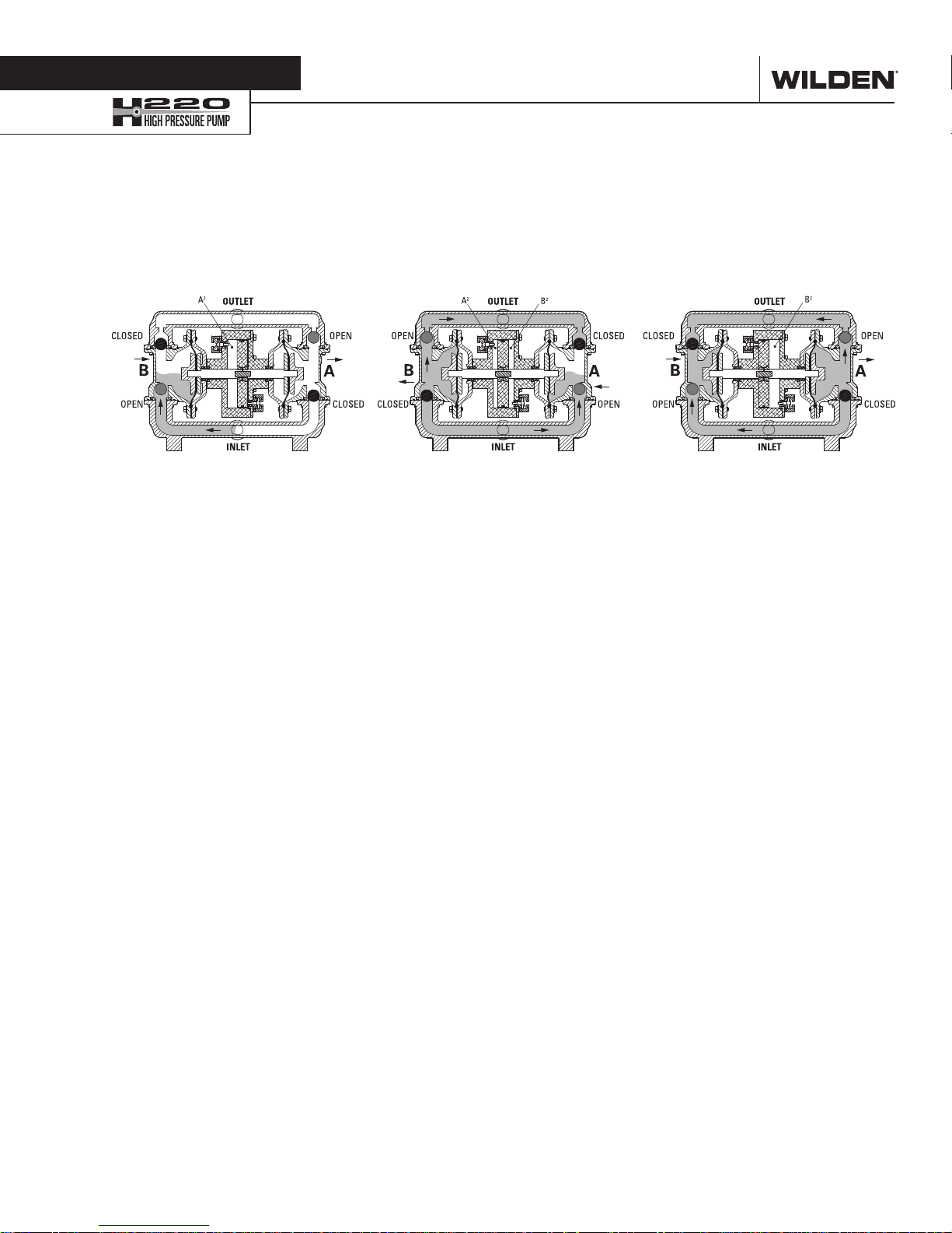
The Wilden diaphragm pump is an air-operated, positive displacement, self-priming pump. These drawings show flow pattern
through the pump upon its initial stroke. It is assumed the pump has no fluid in it prior to its initial stroke.
The H220 uses an integral power amplifier piston together with two diaphragms to yield a pressure ratio of 3:1 [e.g., 6.9 bar
Preface:
(100 psig) air inlet will develop liquid discharge pressures up to 20.7 bar (300 psig)]. In the H220, air is simultaneously directed behind
the amplifier piston a well as one of the diaphragms via specialized air manifold porting. The sum of the two surface areas is three times
that of the diaphragm alone. Therefore, the discharge is amplified by a 3:1 pressure output ratio.
Figure 1 When air pressure is supplied to
the pump, the air valve directs pressure
to the back side of diaphragm (A). The
compressed air moves the diaphragm
away from the center section of the
pump. Simultaneously, compressed air
is also supplied to the back side of the
power piston (A2); pressure on Area A2
exerts force on the shaft communicated
to diaphragm A. This force, when added to
the force of pressure A is connected to the
process fluid, thus providing the increase
of liquid output pressure.
During this operation the opposite
diaphragm (diaphragm B) is pulled in by
a shaft connected to the power piston (A2)
and pressurized diaphragm (A). Diaphragm
(B) is now on its suction stroke; air behind
diaphragm (B) and piston (B2) is being
forced out to atmosphere through the
exhaust port. The movement of diaphragm
(B) towards the center section of the pump
creates a vacuum within chamber (B).
Atmospheric pressure forces fluid into the
inlet manifold forcing the inlet valve ball
off its seat. Liquid is free to move past the
inlet valve ball and fill the liquid chamber
(see shaded area).
Figure 2 Once the power piston reaches
the end of its stroke, the pressure relief
valve opens. This causes the air valve to
shift. This action redirects pressurized air
to the back side (air side) of diaphragm (B)
as well as the back side of the power piston
(B2). This pressurized air forces diaphragm
(B) away from the center section while
also pulling diaphragm (A) towards the
center section. Diaphragm (B) is now on
its discharge stroke. Diaphragm (B) forces
the inlet valve ball onto its seat due to the
hydraulic forces developed in the liquid
chamber and manifold. The same hydraulic
force unseats the discharge valve ball off
of its seat and forces fluid to flow through
the pump discharge.
The pressure on the diaphragm (B) creates
a force that is combined with the force of
pressure applied to the power piston (B2).
This total load is transferred to the liquid
creating a liquid pressure that is 3 times
the supplied air pressure.
Figure 3 At the completion of the stroke,
once again the pressure relief valve opens
and shifts the air valve. The air valve
redirects air to the back side of diaphragm
(A) and the power piston (A2), the air
behind diaphragm (B) and the power
piston (B2) is now exhausted. As the
pump reaches its original starting position,
each diaphragm has gone through one
suction and one discharge stroke of the
wetted path and one pressure and exhaust
stroke of the air distribution system. This
completes one cycle of the high pressure
H220. NOTE: The pump may take several
cycles to completely prime depending on
the condition of the application.
WIL-11114-E-02
3
WILDEN PUMP & ENGINEERING, LLC
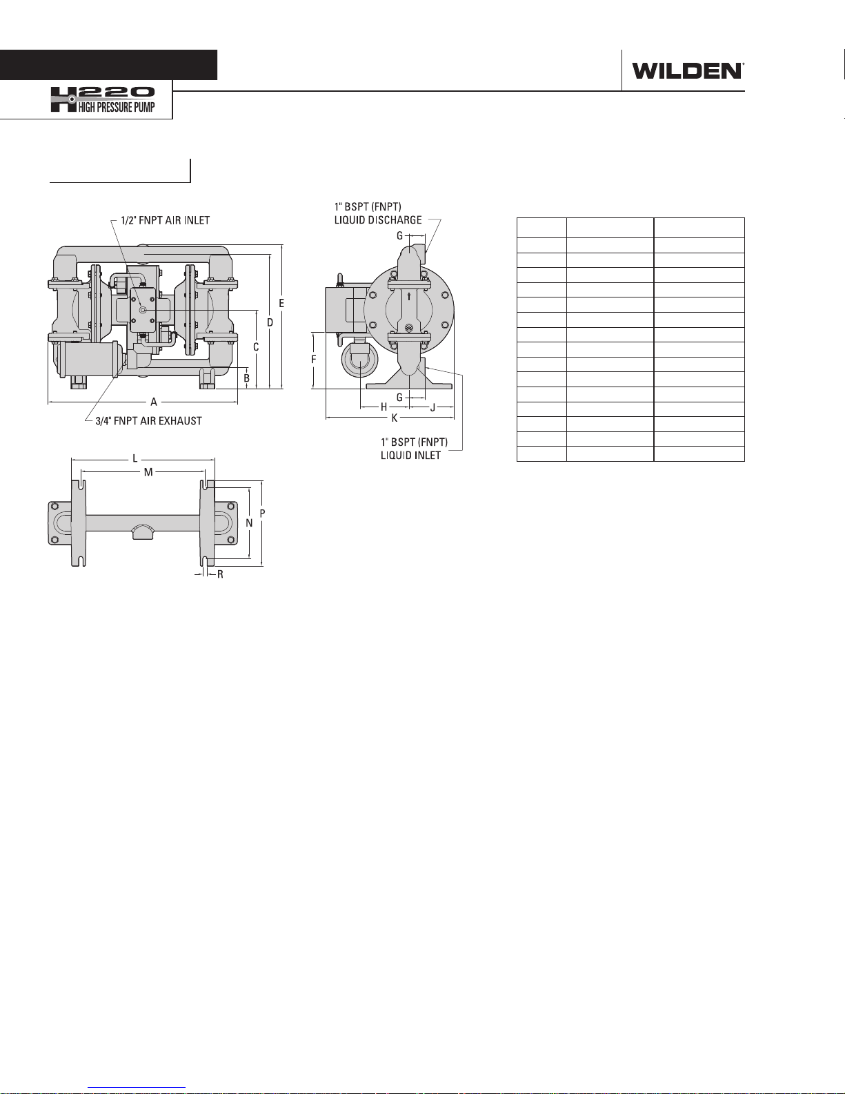
Section 4
H220 Metal
DIMENSIONAL DRAWING
DIMENSIONS
ITEM METRIC (mm) STANDARD (inch)
A 450 17.7
B 51 2.0
C 188 7.4
D 320 12.6
E 343 13.5
F 135 5.3
G 38 1.5
H 114 4.5
J 107 4.2
K 305 12.0
L 340 13.4
M 295 11.6
N 168 6.6
P 203 8.0
R 10 0.4
LW0440 REV. A
WILDEN PUMP & ENGINEERING, LLC
4
WIL-11114-E-02
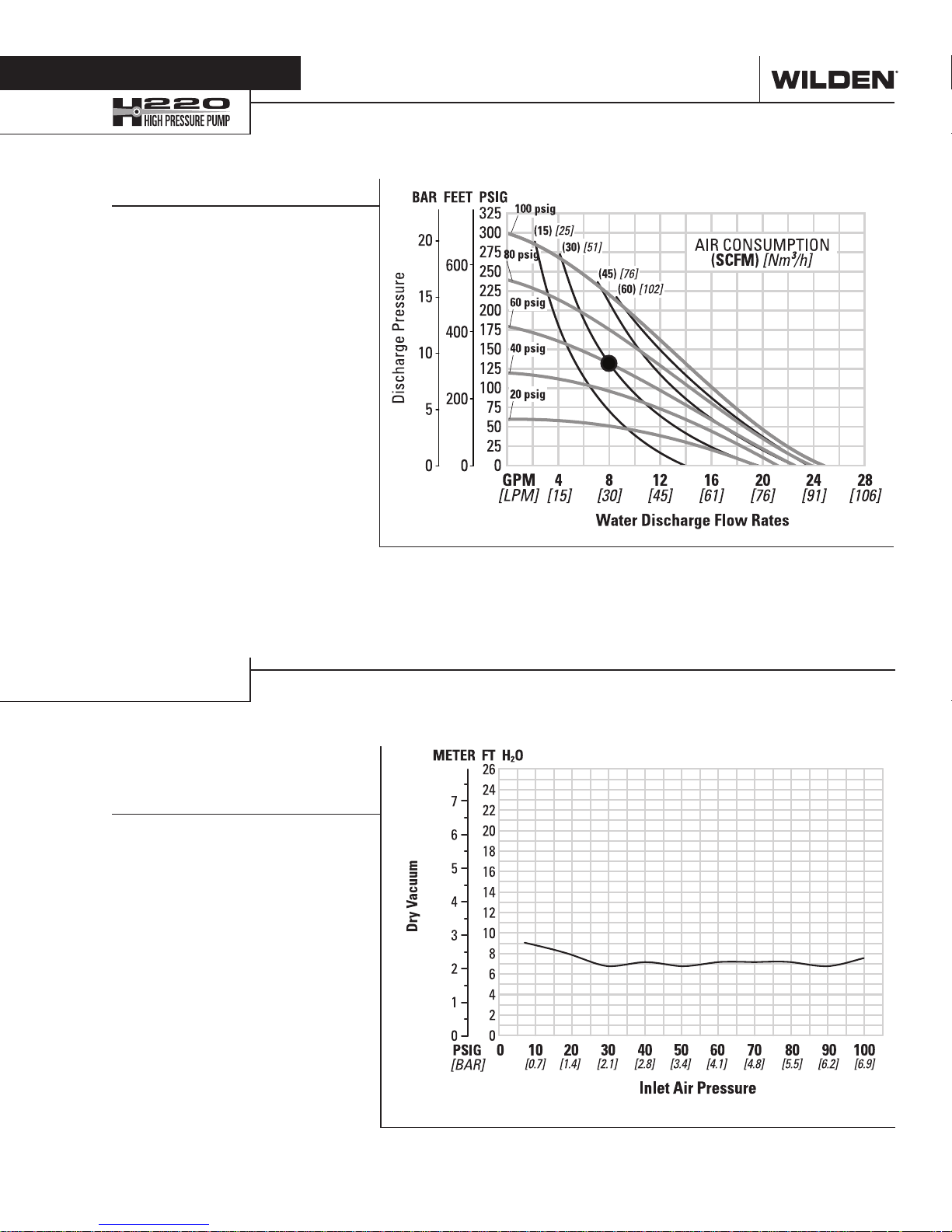
Section 5
PERFORMANCE (TPE/FULL-STROKE PTFE)
H2 20 METAL
Ship Weight .............Ductile Iron 38 kg (84 lb)
Air Inlet ................................... 13 mm (1/2")
Inlet ............................................ 25 mm (1")
Outlet ......................................... 25 mm (1")
Suction Lift ......................... 2.8 m Dry (9.1')
9.0 m Wet (29.5')
Disp. per Stroke¹
Max. Flow Rate .......... 93.9 lpm (24.8 gpm)
Max. Size Solids .................... 6.4 mm (1/4")
Example: To pump 30 lpm (8 gpm) against
a discharge pressure head of 9.0 bar (131
psig) requires 4.1 bar (60 psig) and 51.0
Nm3/h (30 scfm) air consumption. (See dot
on chart.)
Caution: Do not exceed 6.9 bar (100 psig)
air supply pressure.
Stainless Steel 37 kg (81 lb)
................0.189 L (0.05 gal)
Section 5A
SUCTION-LIFT CURVE
H220 METAL HIGHPRESSURE SUCTIONLIFT CAPABILITY
Suction-lift curves are calibrated
for pumps operating at 305 m
(1,000') above sea level. This
chart is meant to be a guide only.
There are many variables which
can affect your pump’s operating
characteristics. The number of
intake and discharge elbows,
viscosity of pumping fluid,
elevation (atmospheric pressure)
and pipe friction loss all affect
the amount of suction lift your
pump will attain.
Flow rates indicated on chart were determined by pumping water.
For optimum life and performance, pumps should be specified so that daily operation
parameters will fall in the center of the pump's performance curve.
Air inlet pressure values are 50% of discharge pressure values shown on Y axis.
WIL-11114-E-02
5
WILDEN PUMP & ENGINEERING, LLC

Section 6
SUGGESTED INSTALLATION
Wilden pumps are designed to meet the performance
requirements of even the most demanding pumping
applications. They have been designed and manufactured
to the highest standards and are available in a variety of
liquid path materials to meet your chemical resistance
needs. Refer to the performance section of this manual for
an in-depth analysis of the performance characteristics of
your pump. Wilden offers the widest variety of elastomer
options in the industry to satisfy temperature, chemical
compatibility, abrasion resistance and flex concerns.
The suction pipe size should be at least the equivalent or
larger than the diameter size of the suction inlet on your
Wilden pump. The suction hose must be non-collapsible,
reinforced type as these pumps are capable of pulling a high
vacuum. Discharge piping should also be the equivalent
or larger than the diameter of the pump discharge which
will help reduce friction losses. It is critical that all fittings
and connections are airtight or a reduction or loss of pump
suction capability will result.
INSTALLATION: Months of careful planning, study,
and selection efforts can result in unsatisfactory pump
performance if installation details are left to chance.
Premature failure and long-term dissatisfaction can be
avoided if reasonable care is exercised throughout the
installation process.
LOCATION: Noise, safety, and other logistical factors usually
dictate where equipment will be situated on the production
floor. Multiple installations with conflicting requirements
can result in congestion of utility areas, leaving few choices
for additional pumps.
Within the framework of these and other existing conditions,
every pump should be located in such a way that six key
factors are balanced against each other to maximum
advantage.
ACCESS: First of all, the location should be accessible. If
it’s easy to reach the pump, maintenance personnel will
have an easier time carrying out routine inspections and
adjustments. Should major repairs become necessary, ease
of access can play a key role in speeding the repair process
and reducing total downtime.
AIR SUPPLY: Every pump location should have an air line
large enough to supply the volume of air necessary to
achieve the desired pumping rate. Use air pressure up to
a maximum of 6.9 bar (100 psig) depending on pumping
requirements.
For best results, the pumps should use a 5μ (micron) air
filter, needle valve and regulator. The use of an air filter
before the pump will ensure that the majority of any pipeline
contaminants will be eliminated.
SOLENOID OPERATION: When operation is controlled by a
solenoid valve in the air line, three-way valves should be
used. This valve allows trapped air between the valve and
the pump to bleed off which improves pump performance.
Pumping volume can be estimated by counting the number
of strokes per minute and then multiplying the figure by the
displacement per stroke.
MUFFLER: Sound levels are reduced below OSHA
specifications using the standard Wilden muffler. Other
mufflers can be used to further reduce sound levels, but
they usually reduce pump performance.
ELEVATION: Selecting a site that is well within the pump’s
dynamic lift capability will assure that loss-of-prime issues will
be eliminated. In addition, pump efficiency can be adversely
affected if proper attention is not given to site location.
PIPING: Final determination of the pump site should not be
made until the piping challenges of each possible location
have been evaluated. The impact of current and future
installations should be considered ahead of time to make
sure that inadvertent restrictions are not created for any
remaining sites.
The best choice possible will be a site involving the shortest
and straightest hook-up of suction and discharge piping.
Unnecessary elbows, bends, and fittings should be avoided.
Pipe sizes should be selected to keep friction losses within
practical limits. All piping should be supported independently
of the pump. In addition, the piping should be aligned to
avoid placing stress on the pump fittings.
Flexible hose can be installed to aid in absorbing the forces
created by the natural reciprocating action of the pump. If the
pump is to be bolted down to a solid location, a mounting
pad placed between the pu mp and the foundation will
assist in minimizing pump vibration. Flexible connections
between the pump and rigid piping will also assist in
minimizing pump vibration. If quick-closing valves are
installed at any point in the discharge system, or if pulsation
within a system becomes a problem, a surge suppressor
(SD Equalizer®) should be installed to protect the pump,
piping and gauges from surges and water hammer.
If the pump is to be used in a self-priming application, make
sure that all connections are airtight and that the suction lift is
within the model’s ability. NOTE: Materials of construction and
elastomer material have an effect on suction lift parameters.
Please refer to the performance section for specifics.
When pumps are installed in applications involving flooded
suction or suction head pressures, a gate valve should be
installed in the suction line to permit closing of the line for
pump service.
Pumps in service with a positive suction head are most efficient
when inlet pressure is limited to 0.5–0.7 bar (7–10 psig).
Premature diaphragm failure may occur if positive suction
is 0.7 bar (10 psig) and higher.
ALL WILDEN PUMPS ARE CAPABLE OF PASSING SOLIDS.
A STRAINER SHOULD BE USED ON THE PUMP INTAKE TO
ENSURE THAT THE PUMP'S RATED SOLIDS CAPACITY IS
NOT EXCEEDED.
CAUTION: DO NOT EXCEED 6.9 BAR (100 PSIG) AIR
SUPPLY PRESSURE.
WILDEN PUMP & ENGINEERING, LLC
6
WIL-11114-E-02
 Loading...