

Wilden T8, A8 Engineering, Operation & Maintenance
T8/A8
Original™ Series PLASTIC Pumps
Simplify your process
EOM
Engineering
Operation &
Maintenance
REPLACES WIL-10230-E- 01
WIL-10230-E-02
TABLE OF CONTENTS
C
l
a
s
s
I
&
I
I
O
z
o
n
e
D
e
p
l
e
t
i
n
g
S
u
b
s
t
a
n
c
e
s
NON
USE
U.S. Clean Air Act
Amendments of 1990
PAGE #
SECTION 1 — CAUTIONS .............................................................................................................. 1
SECTION 2 — PUMP DESIGNATION SYSTEM .......................................................................... 2
SECTION 3 — HOW IT WORKS (PUMP & AIR SYSTEMS) ...................................................... 3
SECTION 4 — DIMENSIONAL DRAWINGS
A. T8 PLASTIC Air-Controlled ................................................................................................ 4
B. A8 PLASTIC Accu-Flo™ .................................................................................................... 4
SECTION 5 — PERFORMANCE CURVES
A. T8 PLASTIC Rubber-Fitted ................................................................................................ 5
B. T8 PLASTIC Ultra-Flex™-Fitted ......................................................................................... 5
C. T8 PLASTIC TPE-Fitted ..................................................................................................... 6
D. T8 PLASTIC PTFE-Fitted ................................................................................................... 6
E. A8 PLASTIC Accu-Flo™ Rubber/TPE-Fitted ..................................................................... 7
F. A8 PLASTIC Accu-Flo™ Rubber/TPE-Fitted 70/30 Operating Condition ......................... 7
G. A8 PLASTIC Accu-Flo™ Ultra-Flex™/PTFE-Fitted ........................................................... 8
H. A8 PLASTIC Accu-Flo™ Ultra-Flex™/PTFE-Fitted 70/30 Operating Condition ............... 8
SECTION 6 — SUCTION LIFT CURVES & DATA
A. T8 PLASTIC Air-Controlled ................................................................................................ 9
B. A8 PLASTIC Accu-Flo™ .................................................................................................... 9
SECTION 7 — INSTALLATION & OPERATION
A. Installation — Air-Controlled Pumps .................................................................................. 10
B. Air-Controlled Operation and Maintenance ....................................................................... 11
C. Accu-Flo™ Operating Principles ....................................................................................... 12
D. Installation — Accu-Flo™ Pumps ...................................................................................... 12
E. Accu-Flo™ Operation and Maintenance ........................................................................... 13
F. Troubleshooting Air-Operated Pumps ............................................................................... 14
G. Troubleshooting Accu-Flo™ Pumps .................................................................................. 14
SECTION 8 — DIRECTIONS FOR DISASSEMBLY/REASSEMBLY
A. T8 PLASTIC Wetted Path — Tools Required ..................................................................... 15
B. Turbo-Flo™ Air Valve — Disassembly, Cleaning, Inspection ........................................... 18
C. Reassembly Hints & Tips, Torque Specs ........................................................................... 20
D. Gasket Kit Installation ........................................................................................................ 21
SECTION 9 — EXPLODED VIEW/PARTS LISTING
A. T8 PLASTIC Rubber/TPE-Fitted ........................................................................................ 22
B. T8 PLASTIC PTFE-Fitted ................................................................................................... 24
C. A8 PLASTIC Accu-Flo™ .................................................................................................... 26
SECTION 10 — REFERENCE
A. Elastomer Options ............................................................................................................. 28
B. Accu-Flo™ Electrical Information ...................................................................................... 28
SECTION 1
T8 PLASTIC
CAUTIONS – READ FIRST!
TEMPERATURE LIMITS:
Polypropylene 0°C to 79°C 32°F to 175°F
PVDF –12°C to 107°C 10°F to 225°F
Neoprene –17.8°C to 93.3°C 0°F to 200°F
Buna-N –12.2°C to 82.2°C 10°F to 180°F
EPDM –51.1°C to 137.8°C –60°F to 280°F
Viton® –40°C to 176.7°C –40°F to 350°F
Wil-Flex™ –40°C to 107.2°C –40°F to 225°F
Polyurethane 12.2°C to 65.6°C 10°F to 150°F
Saniflex™ –28.9°C to 104.4°C –20°F to 220°F
PTFE 4.4°C to 104.4°C 40°F to 220°F
Tetra-Flex™ PTFE 4.4°C to 107.2°C 40°F to 225°F
W/Neoprene
Tetra-Flex™ PTFE -10°C to 137°C 14°F to 280°F
W/EPDM
Tetra-Flex™ PTFE 4.4°C to 176.6°C 40°F to 350°F
CAUTION: When choosing pump materials, be sure
to check the temperature limits for all wetted components. Example: Viton
(350°F) but polypropylene has a maximum limit of only
79°C (175°F).
CAUTION: Maximum temperature limits are based
upon mechanical stress only. Certain chemicals will
significantly reduce maximum safe operating temperatures. Consult engineering guide for chemical compatibility and temperature limits.
CAUTION: Always wear safety glasses when operating pump. If diaphragm rupture occurs, material being
pumped may be forced out air exhaust.
WARNING: Prevention of static sparking — If static
sparking occurs, fire or explosion could result. Pump,
valves, and containers must be properly grounded when
handling flammable fluids and whenever discharge of
static electricity is a hazard.
CAUTION: Do not exceed 8.6 bar (125 psig) air supply
pressure.
CAUTION: Before any maintenance or repair is
attempted, the compressed air line to the pump should
be disconnected and all air pressure allowed to bleed
from pump. Disconnect all intake, discharge and air
lines. Drain the pump by turning it upside down and
allowing any fluid to flow into a suitable container.
®
has a maximum limit of 176.7°C
CAUTION: Blow out air line for 10 to 20 seconds
before attaching to pump to make sure all pipe line
debris is clear. Use an in-line air filter. A 5µ (micron) air
filter is recommended.
NOTE: When installing PTFE diaphragms, it is important to tighten outer pistons simultaneously (turning in
opposite directions) to ensure tight fit.
NOTE: Tighten clamp bands and retainers prior to
installation. Fittings may loosen during transportation.
NOTE: Before starting disassembly, mark a line from
each liquid chamber to its corresponding air chamber.
This line will assist in proper alignment during reassembly.
CAUTION: Verify the chemical compatibility of the
process and cleaning fluid to the pump’s component
materials in the Chemical Resistance Guide (see E4).
NOTE: Pastic series pumps are made of virgin plastic
and are not UV stabilized. Direct sunlight for prolonged
periods can cause deterioration of plastics.
CAUTION: When removing the end cap using
compressed air, the air valve end cap may come out
with considerable force. Hand protection such as a
padded glove or rag should be used to capture the
end cap.
CAUTION: Only explosion proof (NEMA 7) solenoid
valves should be used in areas where explosion proof
equipment is required.
NOTE: Non lube-free pumps must be lubricated.
Wilden suggests an arctic ISO grade 15 (5 weight oil).
Do not over-lubricate air supply. Over-lubrication will
reduce pump performance.
1
WILDEN PUMP & ENGINEERING, LLCWIL-10230-E-02

SECTION 2
WILDEN PUMP DESIGNATION SYSTEM
T or A8X/XXXXX/ XXX/XX/XXX/ XXXX
MODEL VALVE SEAT
VALVE BALLS
DIAPHRAGMS
AIR VALVE
CENTER BLOCK
AIR CHAMBERS
WETTED PARTS & OUTER PISTON
AIR SYSTEM BASE TYPE
O-RINGS
SPECIALTY
CODE
(if applicable)
MODEL P2 METAL MATERIAL CODES
AIR SYSTEM BASE TYPE
T = TURBO-FLO
™
WETTED PARTS & OUTER PISTON
PK = POLYPROPYLENE / PVDF
PP = POLYPROPYLENE /
POLYPROPYLENE
AIR CHAMBERS
A = ALUMINUM
C = PTFE-COATED ALUMINUM
N = NICKEL-PLATED ALUMINUM
S = STAINLESS STEEL
W = CAST IRON
CENTER BLOCK
A = ALUMINUM
C = PTFE-COATED ALUMINUM
N = NICKEL-PLATED ALUMINUM
P = POLYPROPYLENE
S = STAINLESS STEEL
AIR VALVE
A = ALUMINUM
B = BRASS
C = PTFE PFA COATED
D = BRASS W/OIL BOTTLE
N = NICKEL PLATED ALUMINUM
S = STAINLESS STEEL
DIAPHRAGMS
BNS = BUNA-N (Red Dot)
FSS = SANIFLEX™
[Hytrel® (Cream)]
EPS = EPDM (Blue Dot)
NES = NEOPRENE (Green Dot)
PUS = POLYURETHANE (Clear)
TEU = PTFE W/EPDM
BACK-UP (White)
TNU = PTFE W/NEOPRENE
BACK-UP (White)
TSU = PTFE W/SANIFLEX™ BACK-UP
(White)
BNU = BUNA-N, ULTRA-FLEX™ (Red
Dot)
EPU = EPDM, ULTRA-FLEX™ (Blue Dot)
NEU = NEOPRENE, ULTRA-FLEX™
(Green Dot)
VTU = VITON®, ULTRA-FLEX™ (White
Dot)
VTS = VITON® (White Dot)
WFS = WIL-FLEX™ [Santoprene®
(Orange Dot)]
VALVE BALL
BN = BUNA-N (Red Dot)
FS = SANIFLEX™
[Hytrel® (Cream)]
EP = EPDM (Blue Dot)
NE = NEOPRENE (Green Dot)
PU = POLYURETHANE (Brown)
TF = PTFE (White)
VT = VITON® (White Dot)
WF = WIL-FLEX™ [Santoprene® (Orange
Dot)]
VALVE SEAT
K = PVDF
P = POLYPROPYLENE
VALVE SEAT O-RING
BN = BUNA-N
PU = POLYURETHANE
TV = PTFE ENCAP. VITON®
WF = WIL-FLEX™ [Santoprene® (Orange
Dot)]
SPECIALTY CODES
0100 Wil-Gard II™ 110V
0102 Wil-Gard II™, sensor wires ONLY
0103 Wil-Gard II™ 220V
0145 Accu-Flo™, 110V AC x-proof coil, Wil-Gard II™ 110V
0150 Accu-Flo™, 24V DC coil
0151 Accu-Flo™, 24V AC / 12V DC coil
0153 Accu-Flo™, 24V AC / 12V DC x-proof coil
0154 Accu-Flo™, 24V DC x-proof coil
0155 Accu-Flo™, 110V AC coil
0156 Accu-Flo™, 110V AC x-proof coil
0157 Accu-Flo™, 24V DC coil, international,
PTB approved
0164 Accu-Flo™, 110V AC coil,
Wil-Gard sensor wires only
0167 Accu-Flo™ 24V AC / 12V DC coil,
Wil-Gard II™ 110V
NOTE: MOST ELASTOMERIC MATERIALS USE COLORED DOTS FOR IDENTIFICATION.
Viton is a registered trademarks of DuPont Dow Elastomers.
WILDEN PUMP & ENGINEERING, LLC WIL-10230-E-02
0168 Accu-Flo™, 110V AC coil, Wil-Gard II™ 110V
0169 Accu-Flo™, 110V AC coil, PFA coated hardware
0170 Accu-Flo™, 110V AC x-proof coil,
PFA coated hardware
0180 Accu-Flo™, 24V AC / 12V DC coil,
PFA coated hardware
0181 Accu-Flo™, 24V AC / 12V DC x-proof coil,
PFA coated hardware
0183 Accu-Flo™, 24V AC / 12V DC x-proof coil,
Wil-Gard II™ 110V
0184 Accu-Flo™, 24V DC coil, PFA coated hardware
0185 Accu-Flo™, 24V DC x-proof coil,
PFA coated hardware
0206 PFA coated hardware,
Wil-Gard II™ sensor wires ONLY
0360 Accu-Flo™, 24V DC coil, DIN flange
2
0362 Accu-Flo™, 110V AC coil, PFA coated hardware,
Wil-Gard II™ 110V
0363 Accu-Flo™, 110V AC coil, Stallion
(balls & seats)
0502 PFA coated hardware
0513 SS outer pistons
0560 Split manifold
0561 Split manifold, PFA coated hardware
0563 Split manifold, discharge ONLY
0564 Split manifold, inlet ONLY
0608 PFA coated hardware, Wil-Gard II™ 220V
0660 Split manifold, Wil-Gard II™ 110V
0661 Split manifold, PFA coated hardware,
Wil-Gard II™ 110V
®
internals
SECTION 3
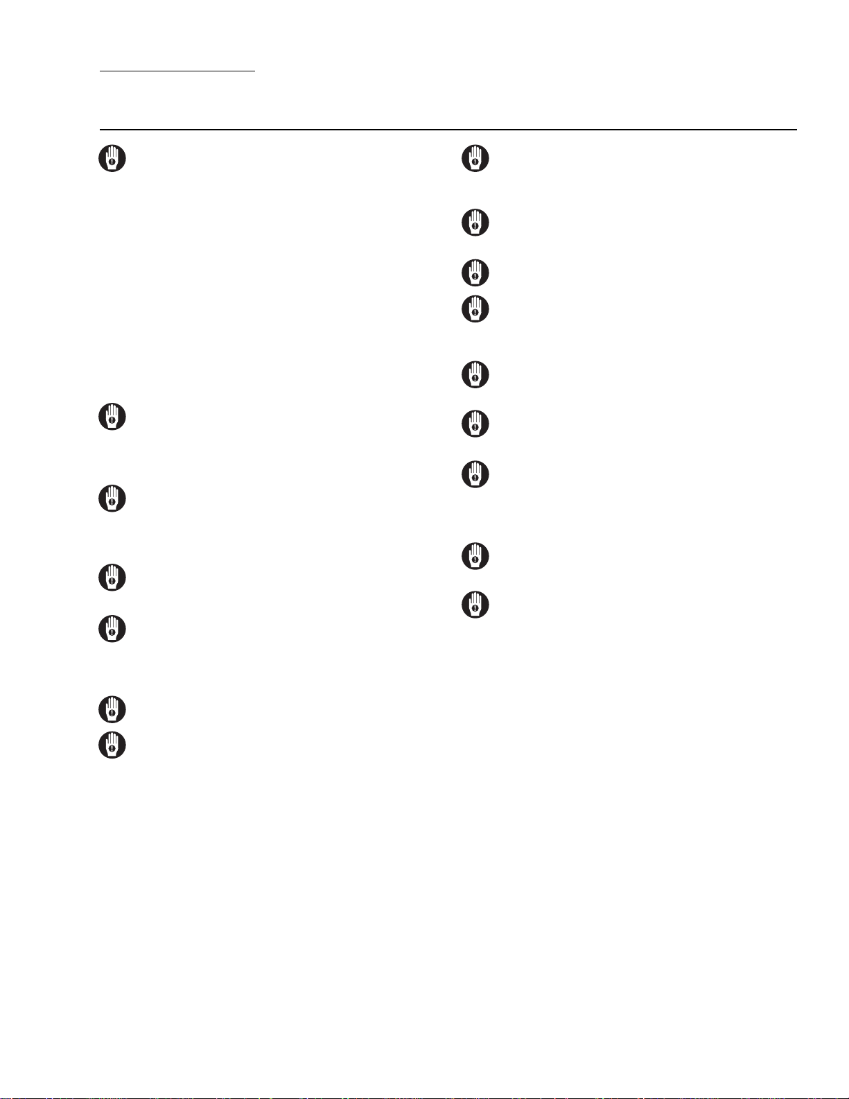
THE WILDEN PUMP — HOW IT WORKS
The Wilden diaphragm pump is an air-operated, positive displacement, self-priming pump. These drawings show the flow
pattern through the pump upon its initial stroke. It is assumed the pump has no fluid in it prior to its initial stroke.
OUTLET
OUTLET
OUTLET
CLOSED
B
AIR SUPPL Y
A
INLET
OPEN
CLOSEDOPEN
RIGHT STROKE MID STROKE LEFT STROKE
FIGURE 1 The air valve directs pressurized air to the back side of diaphragm
A. The compressed air is applied directly
to the liquid column separated by elastomeric diaphragms. The diaphragm
acts as a separation membrane between
the compressed air and liquid, balancing the load and removing mechanical stress from the diaphragm. The
compressed air moves the diaphragm
away from the center block of the pump.
The opposite diaphragm is pulled in by
the shaft connected to the pressurized diaphragm. Diaphragm B is on its
suction stroke; air behind the diaphragm
has been forced out to the atmosphere
through the exhaust port of the pump.
The movement of diaphragm B toward
the center block of the pump creates a
vacuum within chamber B. Atmospheric
pressure forces fluid into the inlet manifold forcing the inlet valve ball off its
seat. Liquid is free to move past the inlet
valve ball and fill the liquid chamber (see
shaded area).
OPEN
CLOSED
AIR SUPPL Y
B
INLET
CLOSED
A
OPEN
FIGURE 2 When the pressurized
diaphragm, diaphragm A, reaches the
limit of its discharge stroke, the air valve
redirects pressurized air to the back
side of diaphragm B. The pressurized
air forces diaphragm B away from the
center block while pulling diaphragm A
to the center block. Diaphragm B is now
on its discharge stroke. Diaphragm B
forces the inlet valve ball onto its seat
due to the hydraulic forces developed
in the liquid chamber and manifold of
the pump. These same hydraulic forces
lift the discharge valve ball off its seat,
while the opposite discharge valve ball is
forced onto its seat, forcing fluid to flow
through the pump discharge. The movement of diaphragm A toward the center
block of the pump creates a vacuum
within liquid chamber A. Atmospheric
pressure forces fluid into the inlet manifold of the pump. The inlet valve ball
is forced off its seat allowing the fluid
being pumped to fill the liquid chamber.
OPEN
CLOSED
AIR SUPPL Y
B
INLET
CLOSED
A
OPEN
FIGURE 3 At completion of the stroke,
the air valve again redirects air to the
back side of diaphragm A, which starts
diaphragm B on its exhaust stroke. As
the pump reaches its original starting
point, each diaphragm has gone through
one exhaust and one discharge stroke.
This constitutes one complete pumping cycle. The pump may take several
cycles to completely prime depending
on the conditions of the application.
3
WILDEN PUMP & ENGINEERING, LLCWIL-10230-E-02
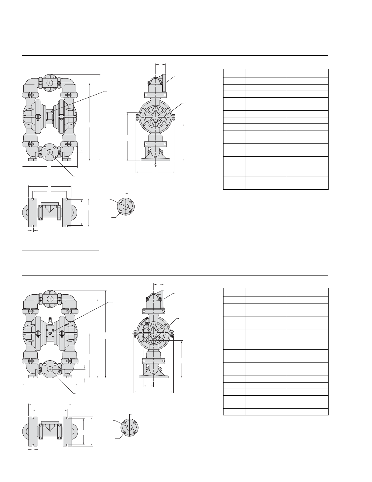
SECTION 4A
DIMENSIONAL DRAWING
T8 PLASTIC
F
51 mm (2")
DIN (ANSI)
19 mm (3/4")
FNPT
AIR INLET
D
C
E
B
A
51 mm (2")
J
K
N
DIN (ANSI)
LIQUID INLET
M
L
R
P
S
FLANGE
H
LIQUID
DISCHARGE
19 mm (3/4")
FNPT
AIR EXHAUST
G
DIMENSIONS
ITEM METRIC (mm) STANDARD (inch)
A 490 19.3
B 76 3.0
C 693 27.3
D 770 30.3
E 447 17.6
F 89 3.5
G 345 13.6
H 333 13.1
J 386 15.2
K 307 12.1
L 229 9.0
M 254 10.0
N 15 0.6
DIN (mm) ANSI (inch)
P 125 DIA. 4.8 DIA.
R 165 DIA. 6.0 DIA.
S 18 DIA. 0.8 DIA.
SECTION 4B
DIMENSIONAL DRAWING
A8 PLASTIC ACCU-FLO™
F
19 mm (3/4")
FNPT
AIR INLET
E
D
C
B
A
51 mm (2")
DIN (ANSI)
K
L
LIQUID INLET
R
J
H
S
51 mm (2")
DIN (ANSI)
LIQUID
DISCHARGE
19 mm (3/4")
FNPT
AIR EXHAUST
G
DIMENSIONS
ITEM METRIC (mm) STANDARD (inch)
A 490 19.3
B 76 3.0
C 409 16.1
D 693 27.3
E 770 30.3
F 89 3.5
G 345 13.6
H 333 13.1
J 86 3.4
K 386 15.2
L 307 12.1
M 229 9.0
N 254 10.0
P 15 0.6
DIN (mm) ANSI (inch)
R 125 DIA. 4.8 DIA.
S 165 DIA. 6.0 DIA.
T 18 DIA. 0.8 DIA.
N
M
P
WILDEN PUMP & ENGINEERING, LLC WIL-10230-E-02
T
FLANGE
4
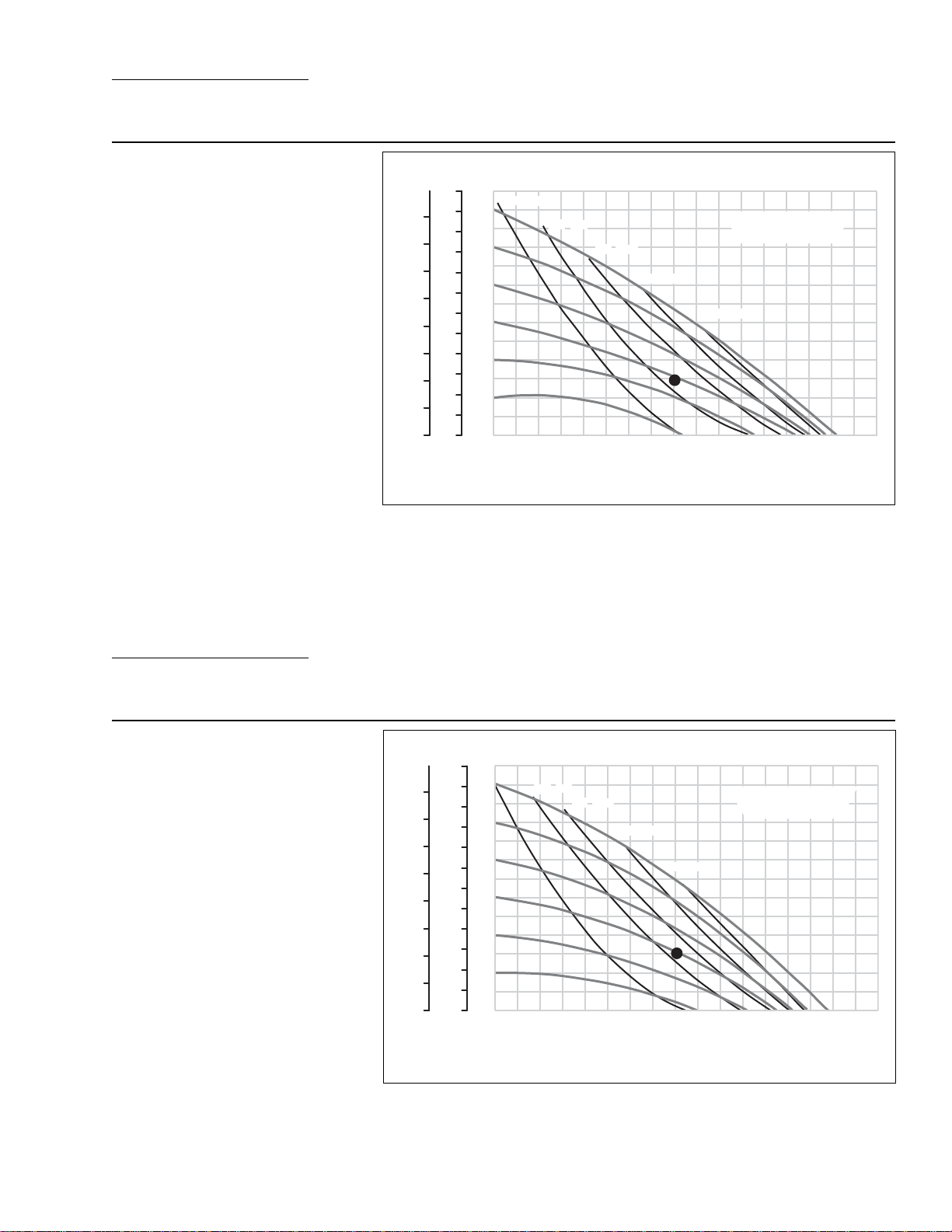
SECTION 5A
PERFORMANCE CURVES
T8 PLASTIC RUBBER-FITTED
Height ..................................770 mm (30.3”)
Width ...................................490 mm (19.3”)
Depth .................................. 333 mm (13.1”)
Est. Ship Weight ........Polypropylene 35 kg (77 lbs)
Air Inlet ....................................19 mm (3/4”)
Inlet ............................................51 mm (2”)
Outlet ......................................... 51 mm (2”)
Suction Lift .......................... 2.7 m Dr y (9.0’)
9.5 m Wet (31.0’)
Displacement / Stroke ...... 2.84 l (0.75gal.)
1
Max. Flow Rate ...............579 lpm (153 gpm)
Max. Size Solids ..................... 6.4 mm (1/4”)
1
Displacement per stroke was calculated at 4.8 bar
(70 psig) air inlet pressure against a 2 bar (30 psig)
head pressure.
Example: To pump 303 lpm (80 gpm) against
a discharge pressure head of 2 bar (30 psig)
requires 4.1 bar (60 psig) and 80 Nm
3
/h (47
scfm) air consumption. (See dot on chart.)
Caution: Do not exceed 8.6 bar (125 psig) air
supply pressure.
Flow rates indicated on chart were determined by pumping water.
For optimum life and performance, pumps should be specified so that daily operation parameters
will fall in the center of the pump performance curve.
e
Discharge Pressur
BAR
8
7
6
5
4
3
2
1
0
FEET
300
275
250
225
200
175
150
125
100
75
50
25
0
PSIG
120
100
80
60
40
20
GPM
[LPM]
(20) [34]
(40) [68]
(60) [102]
(80) [136]
AIR CONSUMPTION
(SCFM) [Nm
(100) [170]
20 40 60 80 100 120 140 160
[76]
[151]
[227]
[303] [378] [454]
[530]
Water Discharge Flow Rates
3
/h]
[606]
SECTION 5B
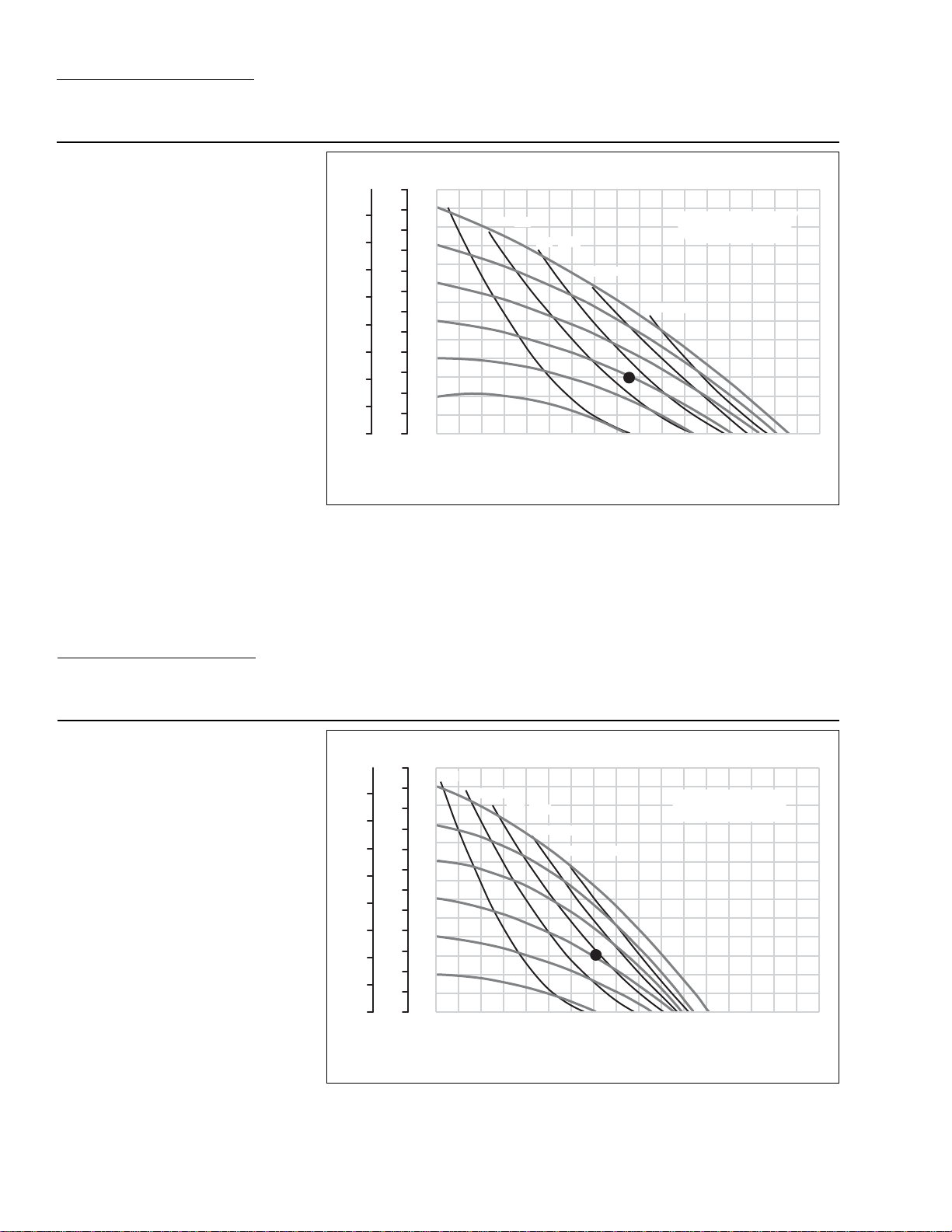
PERFORMANCE CURVES
T8 PLASTIC ULTRA-FLEX™-FITTED
Height ..................................770 mm (30.3”)
Width ...................................490 mm (19.3”)
Depth .................................. 333 mm (13.1”)
Est. Ship Weight ........Polypropylene 35 kg (77 lbs)
Air Inlet ....................................19 mm (3/4”)
Inlet ............................................51 mm (2”)
Outlet ......................................... 51 mm (2”)
Suction Lift ........................... 3.4 m Dr y (11’)
9.1 m Wet (30’)
Displacement / Stroke ..... 1.74 l (0.46 gal.)
1
Max. Flow Rate ...............556 lpm (147 gpm)
Max. Size Solids ..................... 6.4 mm (1/4”)
1
Displacement per stroke was calculated at 4.8 bar
(70 psig) air inlet pressure against a 2 bar (30 psig)
head pressure.
Example: To pump 303 lpm (80 gpm) against
a discharge pressure head of 2 bar (30 psig)
requires 4.1 bar (60 psig) and 82 Nm
3
/h (48
scfm) air consumption. (See dot on chart.)
Caution: Do not exceed 8.6 bar (125 psig) air
supply pressure.
BAR
8
7
6
5
4
Discharge Pressure
3
2
1
0
Flow rates indicated on chart were determined by pumping water.
For optimum life and performance, pumps should be specified so that daily operation parameters
will fall in the center of the pump performance curve.
FEET
300
275
250
225
200
175
150
125
100
75
50
25
0
PSIG
120
100
80
60
40
20
GPM
[LPM]
(20) [34]
(40)
[68]
20 40 60 80 100 120 140 160
[76] [151] [227] [303] [378] [454] [530]
(60) [102]
(80) [136]
(100) [170]
Water Discharge Flow Rates
AIR CONSUMPTION
(SCFM) [Nm
3
/h]
[606]
5
WILDEN PUMP & ENGINEERING, LLCWIL-10230-E-02
SECTION 5C
PERFORMANCE CURVES
T8 PLASTIC TPE-FITTED
Height ..................................770 mm (30.3”)
Width ...................................490 mm (19.3”)
Depth .................................. 333 mm (13.1”)
Est. Ship Weight ........Polypropylene 35 kg (77 lbs)
Air Inlet ....................................19 mm (3/4”)
Inlet ............................................51 mm (2”)
Outlet ......................................... 51 mm (2”)
Suction Lift ........................... 4.6 m Dr y (15’)
9.5 m Wet (31’)
Displacement / Stroke ..... 2.91 l (0.77 gal.)
1
Max. Flow Rate ...............591 lpm (156 gpm)
Max. Size Solids ..................... 6.4 mm (1/4”)
1
Displacement per stroke was calculated at 4.8 bar
(70 psig) air inlet pressure against a 2 bar (30 psig)
head pressure.
Example: To pump 322 lpm (85 gpm) against
a discharge pressure head of 2 bar (30 psig)
requires 4.1 bar (60 psig) and 85 Nm
3
/h (50
scfm) air consumption. (See dot on chart.)
Caution: Do not exceed 8.6 bar (125 psig) air
supply pressure.
BAR
FEET
300
275
8
250
7
225
6
200
175
5
150
4
125
Discharge Pressure
3
100
75
2
50
1
25
0
0
Flow rates indicated on chart were determined by pumping water.
For optimum life and performance, pumps should be specified so that daily operation parameters
will fall in the center of the pump performance curve.
PSIG
120
100
80
60
40
20
GPM
[LPM]
(20) [34]
(40) [68]
(60) [102]
(80) [136]
AIR CONSUMPTION
(SCFM) [Nm
(100) [170]
20 40 60 80 100 120 140 160
[76] [151] [227] [303] [378] [454] [530]
Water Discharge Flow Rates
3
/h]
[606]
SECTION 5D
PERFORMANCE CURVES
T8 PLASTIC PTFE-FITTED
Height ..................................770 mm (30.3”)
Width ...................................490 mm (19.3”)
Depth .................................. 333 mm (13.1”)
Est. Ship Weight ........Polypropylene 35 kg (77 lbs)
Air Inlet ....................................19 mm (3/4”)
Inlet ............................................51 mm (2”)
Outlet ......................................... 51 mm (2”)
Suction Lift ........................... 3.1 m Dr y (10’)
9.5 m Wet (31’)
Displacement / Stroke ...... 1.51 l (0.40 gal)
1
Max. Flow Rate ...............458 lpm (121 gpm)
Max. Size Solids ..................... 6.4 mm (1/4”)
1
Displacement per stroke was calculated at 4.8 bar
(70 psig) air inlet pressure against a 2 bar (30 psig)
head pressure.
Example: To pump 265 lpm (70 gpm) against
a discharge pressure head of 2 bar (30 psig)
requires 4.1 bar (60 psig) and 93.5 Nm
3
/
h (55 scfm) air consumption. (See dot on
chart.)
Caution: Do not exceed 8.6 bar (125 psig) air
supply pressure.
Flow rates indicated on chart were determined by pumping water.
For optimum life and performance, pumps should be specified so that daily operation parameters
will fall in the center of the pump performance curve.
BAR
e
Discharge Pressur
FEET
300
275
8
250
7
225
6
200
175
5
150
4
125
3
100
75
2
50
1
25
0
0
PSIG
120
100
80
60
40
20
GPM
[LPM]
(20) [34]
(40) [68]
(60)
[102]
(80) [136]
(100) [170]
AIR CONSUMPTION
(SCFM) [Nm
20 40 60 80 100 120 140 160
[76] [151] [227] [303] [378] [454] [530]
Water Discharge Flow Rates
3
/h]
[606]
WILDEN PUMP & ENGINEERING, LLC WIL-10230-E-02
6

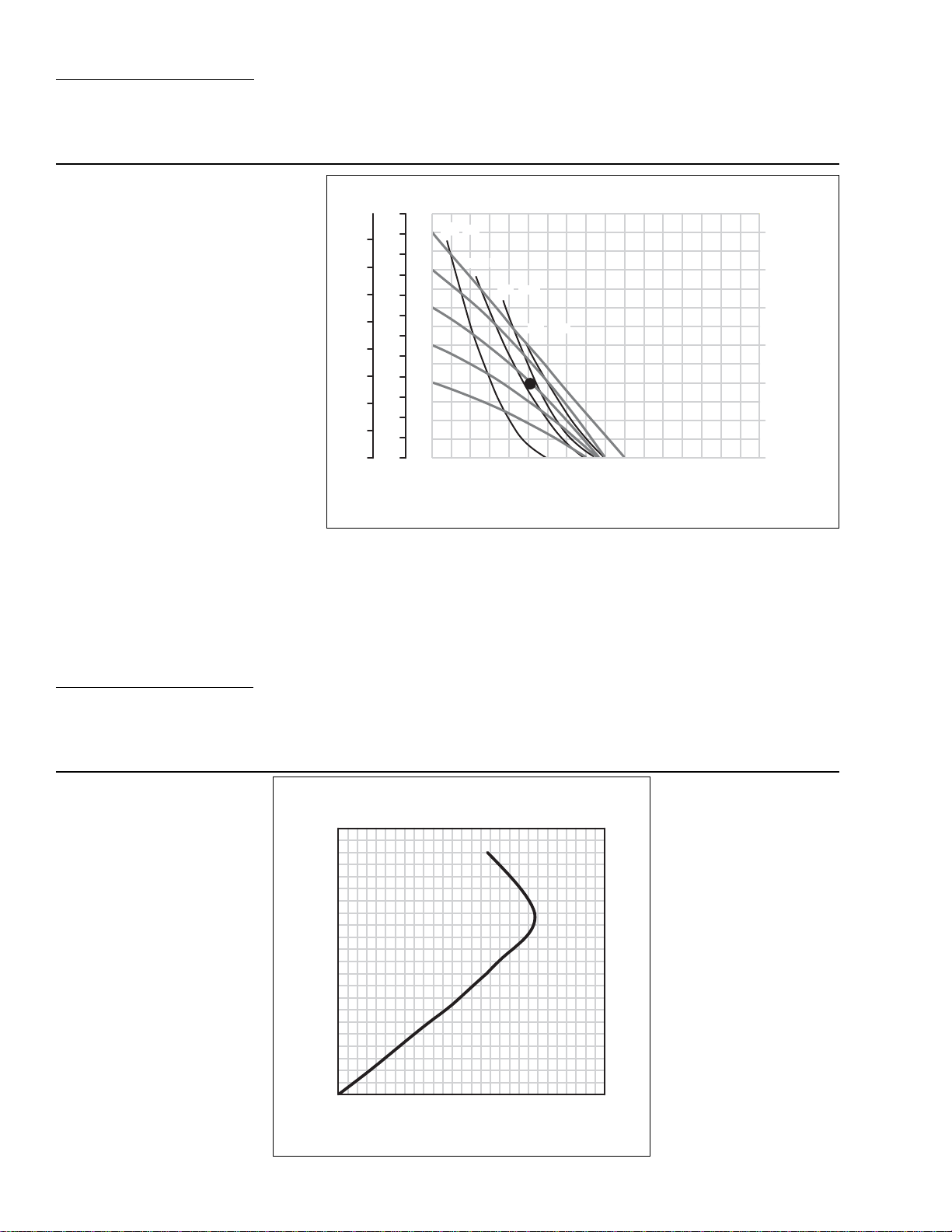
SECTION 5E
PERFORMANCE CURVES
A8 PLASTIC ACCU-FLO™ RUBBER/TPE-FITTED
Height ..................................770 mm (30.3”)
Width ...................................490 mm (19.3”)
Depth .................................. 333 mm (13.1”)
Est. Ship Weight ........Polypropylene 34 kg (75 lbs)
PVDF 43 kg (95 lbs)
Air Inlet ....................................19 mm (3/4”)
Inlet ............................................51 mm (2”)
Outlet ......................................... 51 mm (2”)
Suction Lift ........................... 6.1 m Dr y (20’)
8.5 m Wet (28’)
Displacement / Stroke ..... 0.55 gal. (2.08 l)
Max. Flow Rate ...............420 lpm (111 gpm)
Max. Size Solids ..................... 6.4 mm (1/4”)
1
Displacement per stroke was calculated at 4.8 bar
(70 psig) air inlet pressure against a 2 bar (30 psig)
head pressure.
Example: To pump 197 lpm (52 gpm) against
a discharge pressure head of 2.7 bar (40 psig)
requires 5.5 bar (80 psig) inlet air pressure,
3
68 Nm
/h (40 scfm) air consumption and a
pump speed of 108 strokes/minute. (See dot
on chart.)
Caution: Do not exceed 8.6 bar (125 psig) air
supply pressure.
1
SECTION 5F
3
/h]
Sec / Stroke
Interval
0.9
0.8
0.7
0.6
0.5
0.4
[606]
[SPM]
[67]
[75]
[86]
[100]
[120]
[150]
Optimal Speed
BAR
FEET
PSIG
300
275
8
250
7
225
e
6
200
175
5
150
4
125
Discharge Pressur
3
100
75
2
50
1
25
0
0
Flow curves are for “optimal speed” conditions only. The “optimal speed” is that speed which
provides the maximum flow under a particular air and fluid pressure condition. The optimal speed
varies for different fluid and air pressures. Recommendations for optimal speed can be found on
the right side of the flow curve.
Flow rates indicated on chart were determined by pumping water.
For optimum life and performance, pumps should be specified so that daily operation parameters
will fall in the center of the pump performance curve.
Note: TPE suction lift is approximately half that of rubber-fitted.
(20) [34]
120
100
80
60
40
20
GPM
[LPM] [76] [151] [227] [303] [378] [454] [530]
(40) [68]
(60) [102]
(80) [136]
20 40 60 80 100 120 140 160
Water Discharge Flow Rates
AIR CONSUMPTION
(SCFM) [Nm
70/30 OPERATING CONDITION
A8 PLASTIC ACCU-FLO™
RUBBER/TPE-FITTED
This curve demonstrates the flow
created when the stroke rate is modified under a static air and fluid pressure condition. This curve can be
applied to different pressure conditions
to estimate the change in flow due to
stroke rate.
A8 Plastic Accu-Flo™ Rubber / TPE-Fitted
SPM
220
200
180
160
140
120
Speed
100
80
60
40
20
0
GPM
[LPM] [114] [151] [189][38] [76] [227] [265]
@ 70 / 30 operating condition
10 20 30 40 50 60 70
Water Discharge Flow Rate
7
WILDEN PUMP & ENGINEERING, LLCWIL-10230-E-02
SECTION 5G
A
PERFORMANCE CURVES
A8 PLASTIC ACCU-FLO™ ULTRA-FLEX™/PTFE-FITTED
Height ..................................770 mm (30.3”)
Width ...................................490 mm (19.3”)
Depth .................................. 333 mm (13.1”)
Est. Ship Weight ........Polypropylene 34 kg (75 lbs)
PVDF 43 kg (95 lbs)
Air Inlet ....................................19 mm (3/4”)
Inlet ............................................51 mm (2”)
Outlet ......................................... 51 mm (2”)
Suction Lift ........................... 3.4 m Dr y (11’)
8.5 m Wet (28’)
Displacement / Stroke ..... 1.74 l (0.46 gal.)
Max. Flow Rate ...............386 lpm (102 gpm)
Max. Size Solids ..................... 6.4 mm (1/4”)
1
Displacement per stroke was calculated at 4.8 bar
(70 psig) air inlet pressure against a 2 bar (30 psig)
head pressure.
Example: To pump 189 lpm (50 gpm)
against a discharge pressure head of 2.7 bar
(40 psig) requires 5.5 bar (80 psig) inlet air
pressure, 85 Nm
tion and a pump speed of 120 strokes/minute.
(See dot on chart.)
Caution: Do not exceed 8.6 bar (125 psig) air
supply pressure.
3
/h (50 scfm) air consump-
1
SECTION 5H
PSIG
FEET
BAR
300
275
8
250
7
225
e
6
200
175
5
150
4
125
Discharge Pressur
3
100
75
2
50
1
25
0
0
Flow curves are for “optimal speed” conditions only. The “optimal speed” is that speed which
provides the maximum flow under a particular air and fluid pressure condition. The optimal speed
varies for different fluid and air pressures. Recommendations for optimal speed can be found on
the right side of the flow curve.
Flow rates indicated on chart were determined by pumping water.
For optimum life and performance, pumps should be specified so that daily operation parameters
will fall in the center of the pump performance curve.
(20) [34]
120
100
80
60
40
20
GPM
[ LPM] [76] [151] [227] [303] [378] [454] [530]
(40) [68]
(60) [102]
(80) [136]
20 40 60 80 100 120 140 160
Water Discharge Flow Rates
Sec / Stroke
Interval
0.9
0.8
0.7
0.6
0.5
0.4
0.3
[606]
[SPM]
[67]
[75]
[86]
[100]
[120]
[150]
[200]
Optimal Speed
70/30 OPERATING CONDITION
A8 PLASTIC ACCU-FLO™
ULTRA-FLEX™-PTFE-FITTED
This curve demonstrates the flow
created when the stroke rate is modified under a static air and fluid pressure condition. This curve can be
applied to different pressure conditions
to estimate the change in flow due to
stroke rate.
8 Plastic Accu-Flo™ Ultra-Flex™/PTFE-Fitted
SPM
220
200
180
160
140
120
Speed
100
80
60
40
20
0
GPM
[LPM]
@ 70 / 30 operating condition
10 20 30 40 50 60 70
[114] [151] [189][38] [76] [227] [265]
Water Discharge Flow Rate
WILDEN PUMP & ENGINEERING, LLC WIL-10230-E-02
8
 Loading...