

Page 1
T8/A8
Original™ Series PLASTIC Pumps
Simplify your process
EOM
Engineering
Operation &
Maintenance
REPLACES WIL-10230-E- 01
WIL-10230-E-02
Page 2
TABLE OF CONTENTS
C
l
a
s
s
I
&
I
I
O
z
o
n
e
D
e
p
l
e
t
i
n
g
S
u
b
s
t
a
n
c
e
s
NON
USE
U.S. Clean Air Act
Amendments of 1990
PAGE #
SECTION 1 — CAUTIONS .............................................................................................................. 1
SECTION 2 — PUMP DESIGNATION SYSTEM .......................................................................... 2
SECTION 3 — HOW IT WORKS (PUMP & AIR SYSTEMS) ...................................................... 3
SECTION 4 — DIMENSIONAL DRAWINGS
A. T8 PLASTIC Air-Controlled ................................................................................................ 4
B. A8 PLASTIC Accu-Flo™ .................................................................................................... 4
SECTION 5 — PERFORMANCE CURVES
A. T8 PLASTIC Rubber-Fitted ................................................................................................ 5
B. T8 PLASTIC Ultra-Flex™-Fitted ......................................................................................... 5
C. T8 PLASTIC TPE-Fitted ..................................................................................................... 6
D. T8 PLASTIC PTFE-Fitted ................................................................................................... 6
E. A8 PLASTIC Accu-Flo™ Rubber/TPE-Fitted ..................................................................... 7
F. A8 PLASTIC Accu-Flo™ Rubber/TPE-Fitted 70/30 Operating Condition ......................... 7
G. A8 PLASTIC Accu-Flo™ Ultra-Flex™/PTFE-Fitted ........................................................... 8
H. A8 PLASTIC Accu-Flo™ Ultra-Flex™/PTFE-Fitted 70/30 Operating Condition ............... 8
SECTION 6 — SUCTION LIFT CURVES & DATA
A. T8 PLASTIC Air-Controlled ................................................................................................ 9
B. A8 PLASTIC Accu-Flo™ .................................................................................................... 9
SECTION 7 — INSTALLATION & OPERATION
A. Installation — Air-Controlled Pumps .................................................................................. 10
B. Air-Controlled Operation and Maintenance ....................................................................... 11
C. Accu-Flo™ Operating Principles ....................................................................................... 12
D. Installation — Accu-Flo™ Pumps ...................................................................................... 12
E. Accu-Flo™ Operation and Maintenance ........................................................................... 13
F. Troubleshooting Air-Operated Pumps ............................................................................... 14
G. Troubleshooting Accu-Flo™ Pumps .................................................................................. 14
SECTION 8 — DIRECTIONS FOR DISASSEMBLY/REASSEMBLY
A. T8 PLASTIC Wetted Path — Tools Required ..................................................................... 15
B. Turbo-Flo™ Air Valve — Disassembly, Cleaning, Inspection ........................................... 18
C. Reassembly Hints & Tips, Torque Specs ........................................................................... 20
D. Gasket Kit Installation ........................................................................................................ 21
SECTION 9 — EXPLODED VIEW/PARTS LISTING
A. T8 PLASTIC Rubber/TPE-Fitted ........................................................................................ 22
B. T8 PLASTIC PTFE-Fitted ................................................................................................... 24
C. A8 PLASTIC Accu-Flo™ .................................................................................................... 26
SECTION 10 — REFERENCE
A. Elastomer Options ............................................................................................................. 28
B. Accu-Flo™ Electrical Information ...................................................................................... 28
Page 3
SECTION 1
T8 PLASTIC
CAUTIONS – READ FIRST!
TEMPERATURE LIMITS:
Polypropylene 0°C to 79°C 32°F to 175°F
PVDF –12°C to 107°C 10°F to 225°F
Neoprene –17.8°C to 93.3°C 0°F to 200°F
Buna-N –12.2°C to 82.2°C 10°F to 180°F
EPDM –51.1°C to 137.8°C –60°F to 280°F
Viton® –40°C to 176.7°C –40°F to 350°F
Wil-Flex™ –40°C to 107.2°C –40°F to 225°F
Polyurethane 12.2°C to 65.6°C 10°F to 150°F
Saniflex™ –28.9°C to 104.4°C –20°F to 220°F
PTFE 4.4°C to 104.4°C 40°F to 220°F
Tetra-Flex™ PTFE 4.4°C to 107.2°C 40°F to 225°F
W/Neoprene
Tetra-Flex™ PTFE -10°C to 137°C 14°F to 280°F
W/EPDM
Tetra-Flex™ PTFE 4.4°C to 176.6°C 40°F to 350°F
CAUTION: When choosing pump materials, be sure
to check the temperature limits for all wetted components. Example: Viton
(350°F) but polypropylene has a maximum limit of only
79°C (175°F).
CAUTION: Maximum temperature limits are based
upon mechanical stress only. Certain chemicals will
significantly reduce maximum safe operating temperatures. Consult engineering guide for chemical compatibility and temperature limits.
CAUTION: Always wear safety glasses when operating pump. If diaphragm rupture occurs, material being
pumped may be forced out air exhaust.
WARNING: Prevention of static sparking — If static
sparking occurs, fire or explosion could result. Pump,
valves, and containers must be properly grounded when
handling flammable fluids and whenever discharge of
static electricity is a hazard.
CAUTION: Do not exceed 8.6 bar (125 psig) air supply
pressure.
CAUTION: Before any maintenance or repair is
attempted, the compressed air line to the pump should
be disconnected and all air pressure allowed to bleed
from pump. Disconnect all intake, discharge and air
lines. Drain the pump by turning it upside down and
allowing any fluid to flow into a suitable container.
®
has a maximum limit of 176.7°C
CAUTION: Blow out air line for 10 to 20 seconds
before attaching to pump to make sure all pipe line
debris is clear. Use an in-line air filter. A 5µ (micron) air
filter is recommended.
NOTE: When installing PTFE diaphragms, it is important to tighten outer pistons simultaneously (turning in
opposite directions) to ensure tight fit.
NOTE: Tighten clamp bands and retainers prior to
installation. Fittings may loosen during transportation.
NOTE: Before starting disassembly, mark a line from
each liquid chamber to its corresponding air chamber.
This line will assist in proper alignment during reassembly.
CAUTION: Verify the chemical compatibility of the
process and cleaning fluid to the pump’s component
materials in the Chemical Resistance Guide (see E4).
NOTE: Pastic series pumps are made of virgin plastic
and are not UV stabilized. Direct sunlight for prolonged
periods can cause deterioration of plastics.
CAUTION: When removing the end cap using
compressed air, the air valve end cap may come out
with considerable force. Hand protection such as a
padded glove or rag should be used to capture the
end cap.
CAUTION: Only explosion proof (NEMA 7) solenoid
valves should be used in areas where explosion proof
equipment is required.
NOTE: Non lube-free pumps must be lubricated.
Wilden suggests an arctic ISO grade 15 (5 weight oil).
Do not over-lubricate air supply. Over-lubrication will
reduce pump performance.
1
WILDEN PUMP & ENGINEERING, LLCWIL-10230-E-02
Page 4
SECTION 2
WILDEN PUMP DESIGNATION SYSTEM
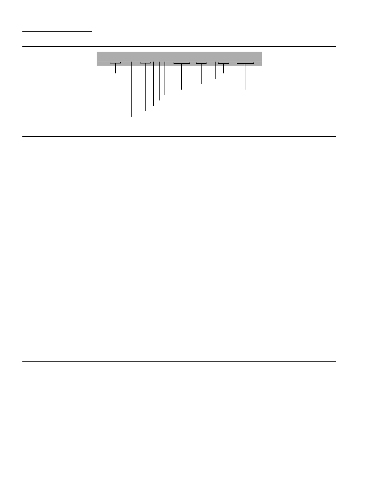
T or A8X/XXXXX/ XXX/XX/XXX/ XXXX
MODEL VALVE SEAT
VALVE BALLS
DIAPHRAGMS
AIR VALVE
CENTER BLOCK
AIR CHAMBERS
WETTED PARTS & OUTER PISTON
AIR SYSTEM BASE TYPE
O-RINGS
SPECIALTY
CODE
(if applicable)
MODEL P2 METAL MATERIAL CODES
AIR SYSTEM BASE TYPE
T = TURBO-FLO
™
WETTED PARTS & OUTER PISTON
PK = POLYPROPYLENE / PVDF
PP = POLYPROPYLENE /
POLYPROPYLENE
AIR CHAMBERS
A = ALUMINUM
C = PTFE-COATED ALUMINUM
N = NICKEL-PLATED ALUMINUM
S = STAINLESS STEEL
W = CAST IRON
CENTER BLOCK
A = ALUMINUM
C = PTFE-COATED ALUMINUM
N = NICKEL-PLATED ALUMINUM
P = POLYPROPYLENE
S = STAINLESS STEEL
AIR VALVE
A = ALUMINUM
B = BRASS
C = PTFE PFA COATED
D = BRASS W/OIL BOTTLE
N = NICKEL PLATED ALUMINUM
S = STAINLESS STEEL
DIAPHRAGMS
BNS = BUNA-N (Red Dot)
FSS = SANIFLEX™
[Hytrel® (Cream)]
EPS = EPDM (Blue Dot)
NES = NEOPRENE (Green Dot)
PUS = POLYURETHANE (Clear)
TEU = PTFE W/EPDM
BACK-UP (White)
TNU = PTFE W/NEOPRENE
BACK-UP (White)
TSU = PTFE W/SANIFLEX™ BACK-UP
(White)
BNU = BUNA-N, ULTRA-FLEX™ (Red
Dot)
EPU = EPDM, ULTRA-FLEX™ (Blue Dot)
NEU = NEOPRENE, ULTRA-FLEX™
(Green Dot)
VTU = VITON®, ULTRA-FLEX™ (White
Dot)
VTS = VITON® (White Dot)
WFS = WIL-FLEX™ [Santoprene®
(Orange Dot)]
VALVE BALL
BN = BUNA-N (Red Dot)
FS = SANIFLEX™
[Hytrel® (Cream)]
EP = EPDM (Blue Dot)
NE = NEOPRENE (Green Dot)
PU = POLYURETHANE (Brown)
TF = PTFE (White)
VT = VITON® (White Dot)
WF = WIL-FLEX™ [Santoprene® (Orange
Dot)]
VALVE SEAT
K = PVDF
P = POLYPROPYLENE
VALVE SEAT O-RING
BN = BUNA-N
PU = POLYURETHANE
TV = PTFE ENCAP. VITON®
WF = WIL-FLEX™ [Santoprene® (Orange
Dot)]
SPECIALTY CODES
0100 Wil-Gard II™ 110V
0102 Wil-Gard II™, sensor wires ONLY
0103 Wil-Gard II™ 220V
0145 Accu-Flo™, 110V AC x-proof coil, Wil-Gard II™ 110V
0150 Accu-Flo™, 24V DC coil
0151 Accu-Flo™, 24V AC / 12V DC coil
0153 Accu-Flo™, 24V AC / 12V DC x-proof coil
0154 Accu-Flo™, 24V DC x-proof coil
0155 Accu-Flo™, 110V AC coil
0156 Accu-Flo™, 110V AC x-proof coil
0157 Accu-Flo™, 24V DC coil, international,
PTB approved
0164 Accu-Flo™, 110V AC coil,
Wil-Gard sensor wires only
0167 Accu-Flo™ 24V AC / 12V DC coil,
Wil-Gard II™ 110V
NOTE: MOST ELASTOMERIC MATERIALS USE COLORED DOTS FOR IDENTIFICATION.
Viton is a registered trademarks of DuPont Dow Elastomers.
WILDEN PUMP & ENGINEERING, LLC WIL-10230-E-02
0168 Accu-Flo™, 110V AC coil, Wil-Gard II™ 110V
0169 Accu-Flo™, 110V AC coil, PFA coated hardware
0170 Accu-Flo™, 110V AC x-proof coil,
PFA coated hardware
0180 Accu-Flo™, 24V AC / 12V DC coil,
PFA coated hardware
0181 Accu-Flo™, 24V AC / 12V DC x-proof coil,
PFA coated hardware
0183 Accu-Flo™, 24V AC / 12V DC x-proof coil,
Wil-Gard II™ 110V
0184 Accu-Flo™, 24V DC coil, PFA coated hardware
0185 Accu-Flo™, 24V DC x-proof coil,
PFA coated hardware
0206 PFA coated hardware,
Wil-Gard II™ sensor wires ONLY
0360 Accu-Flo™, 24V DC coil, DIN flange
2
0362 Accu-Flo™, 110V AC coil, PFA coated hardware,
Wil-Gard II™ 110V
0363 Accu-Flo™, 110V AC coil, Stallion
(balls & seats)
0502 PFA coated hardware
0513 SS outer pistons
0560 Split manifold
0561 Split manifold, PFA coated hardware
0563 Split manifold, discharge ONLY
0564 Split manifold, inlet ONLY
0608 PFA coated hardware, Wil-Gard II™ 220V
0660 Split manifold, Wil-Gard II™ 110V
0661 Split manifold, PFA coated hardware,
Wil-Gard II™ 110V
®
internals
Page 5
SECTION 3
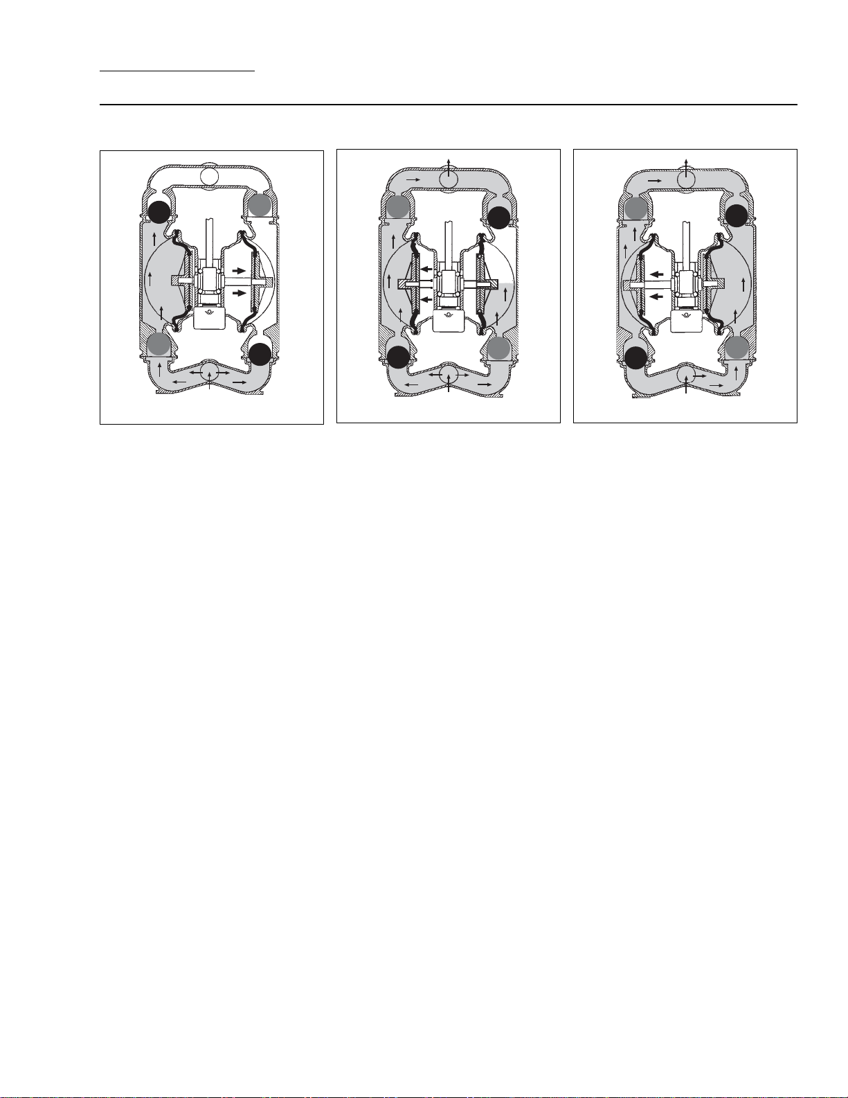
THE WILDEN PUMP — HOW IT WORKS
The Wilden diaphragm pump is an air-operated, positive displacement, self-priming pump. These drawings show the flow
pattern through the pump upon its initial stroke. It is assumed the pump has no fluid in it prior to its initial stroke.
OUTLET
OUTLET
OUTLET
CLOSED
B
AIR SUPPL Y
A
INLET
OPEN
CLOSEDOPEN
RIGHT STROKE MID STROKE LEFT STROKE
FIGURE 1 The air valve directs pressurized air to the back side of diaphragm
A. The compressed air is applied directly
to the liquid column separated by elastomeric diaphragms. The diaphragm
acts as a separation membrane between
the compressed air and liquid, balancing the load and removing mechanical stress from the diaphragm. The
compressed air moves the diaphragm
away from the center block of the pump.
The opposite diaphragm is pulled in by
the shaft connected to the pressurized diaphragm. Diaphragm B is on its
suction stroke; air behind the diaphragm
has been forced out to the atmosphere
through the exhaust port of the pump.
The movement of diaphragm B toward
the center block of the pump creates a
vacuum within chamber B. Atmospheric
pressure forces fluid into the inlet manifold forcing the inlet valve ball off its
seat. Liquid is free to move past the inlet
valve ball and fill the liquid chamber (see
shaded area).
OPEN
CLOSED
AIR SUPPL Y
B
INLET
CLOSED
A
OPEN
FIGURE 2 When the pressurized
diaphragm, diaphragm A, reaches the
limit of its discharge stroke, the air valve
redirects pressurized air to the back
side of diaphragm B. The pressurized
air forces diaphragm B away from the
center block while pulling diaphragm A
to the center block. Diaphragm B is now
on its discharge stroke. Diaphragm B
forces the inlet valve ball onto its seat
due to the hydraulic forces developed
in the liquid chamber and manifold of
the pump. These same hydraulic forces
lift the discharge valve ball off its seat,
while the opposite discharge valve ball is
forced onto its seat, forcing fluid to flow
through the pump discharge. The movement of diaphragm A toward the center
block of the pump creates a vacuum
within liquid chamber A. Atmospheric
pressure forces fluid into the inlet manifold of the pump. The inlet valve ball
is forced off its seat allowing the fluid
being pumped to fill the liquid chamber.
OPEN
CLOSED
AIR SUPPL Y
B
INLET
CLOSED
A
OPEN
FIGURE 3 At completion of the stroke,
the air valve again redirects air to the
back side of diaphragm A, which starts
diaphragm B on its exhaust stroke. As
the pump reaches its original starting
point, each diaphragm has gone through
one exhaust and one discharge stroke.
This constitutes one complete pumping cycle. The pump may take several
cycles to completely prime depending
on the conditions of the application.
3
WILDEN PUMP & ENGINEERING, LLCWIL-10230-E-02
Page 6
SECTION 4A
DIMENSIONAL DRAWING
T8 PLASTIC
F
51 mm (2")
DIN (ANSI)
19 mm (3/4")
FNPT
AIR INLET
D
C
E
B
A
51 mm (2")
J
K
N
DIN (ANSI)
LIQUID INLET
M
L
R
P
S
FLANGE
H
LIQUID
DISCHARGE
19 mm (3/4")
FNPT
AIR EXHAUST
G
DIMENSIONS
ITEM METRIC (mm) STANDARD (inch)
A 490 19.3
B 76 3.0
C 693 27.3
D 770 30.3
E 447 17.6
F 89 3.5
G 345 13.6
H 333 13.1
J 386 15.2
K 307 12.1
L 229 9.0
M 254 10.0
N 15 0.6
DIN (mm) ANSI (inch)
P 125 DIA. 4.8 DIA.
R 165 DIA. 6.0 DIA.
S 18 DIA. 0.8 DIA.
SECTION 4B
DIMENSIONAL DRAWING
A8 PLASTIC ACCU-FLO™
F
19 mm (3/4")
FNPT
AIR INLET
E
D
C
B
A
51 mm (2")
DIN (ANSI)
K
L
LIQUID INLET
R
J
H
S
51 mm (2")
DIN (ANSI)
LIQUID
DISCHARGE
19 mm (3/4")
FNPT
AIR EXHAUST
G
DIMENSIONS
ITEM METRIC (mm) STANDARD (inch)
A 490 19.3
B 76 3.0
C 409 16.1
D 693 27.3
E 770 30.3
F 89 3.5
G 345 13.6
H 333 13.1
J 86 3.4
K 386 15.2
L 307 12.1
M 229 9.0
N 254 10.0
P 15 0.6
DIN (mm) ANSI (inch)
R 125 DIA. 4.8 DIA.
S 165 DIA. 6.0 DIA.
T 18 DIA. 0.8 DIA.
N
M
P
WILDEN PUMP & ENGINEERING, LLC WIL-10230-E-02
T
FLANGE
4
Page 7
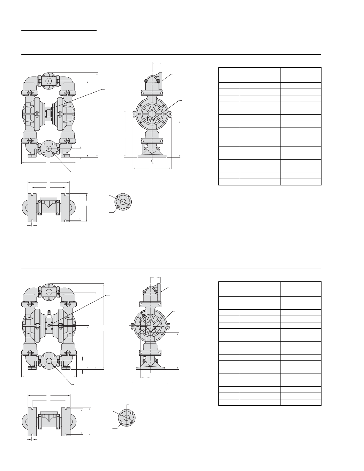
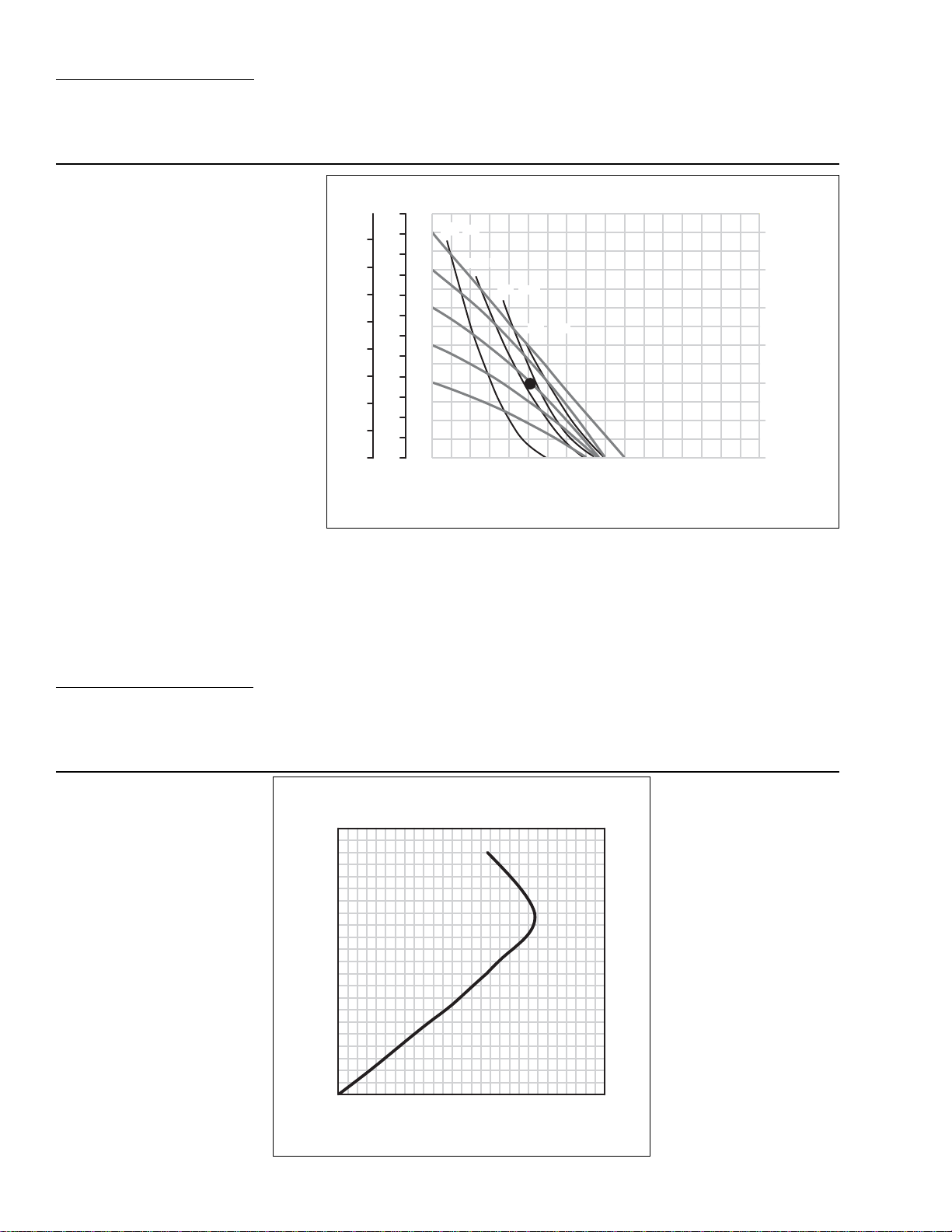
SECTION 5A
PERFORMANCE CURVES
T8 PLASTIC RUBBER-FITTED
Height ..................................770 mm (30.3”)
Width ...................................490 mm (19.3”)
Depth .................................. 333 mm (13.1”)
Est. Ship Weight ........Polypropylene 35 kg (77 lbs)
Air Inlet ....................................19 mm (3/4”)
Inlet ............................................51 mm (2”)
Outlet ......................................... 51 mm (2”)
Suction Lift .......................... 2.7 m Dr y (9.0’)
9.5 m Wet (31.0’)
Displacement / Stroke ...... 2.84 l (0.75gal.)
1
Max. Flow Rate ...............579 lpm (153 gpm)
Max. Size Solids ..................... 6.4 mm (1/4”)
1
Displacement per stroke was calculated at 4.8 bar
(70 psig) air inlet pressure against a 2 bar (30 psig)
head pressure.
Example: To pump 303 lpm (80 gpm) against
a discharge pressure head of 2 bar (30 psig)
requires 4.1 bar (60 psig) and 80 Nm
3
/h (47
scfm) air consumption. (See dot on chart.)
Caution: Do not exceed 8.6 bar (125 psig) air
supply pressure.
Flow rates indicated on chart were determined by pumping water.
For optimum life and performance, pumps should be specified so that daily operation parameters
will fall in the center of the pump performance curve.
e
Discharge Pressur
BAR
8
7
6
5
4
3
2
1
0
FEET
300
275
250
225
200
175
150
125
100
75
50
25
0
PSIG
120
100
80
60
40
20
GPM
[LPM]
(20) [34]
(40) [68]
(60) [102]
(80) [136]
AIR CONSUMPTION
(SCFM) [Nm
(100) [170]
20 40 60 80 100 120 140 160
[76]
[151]
[227]
[303] [378] [454]
[530]
Water Discharge Flow Rates
3
/h]
[606]
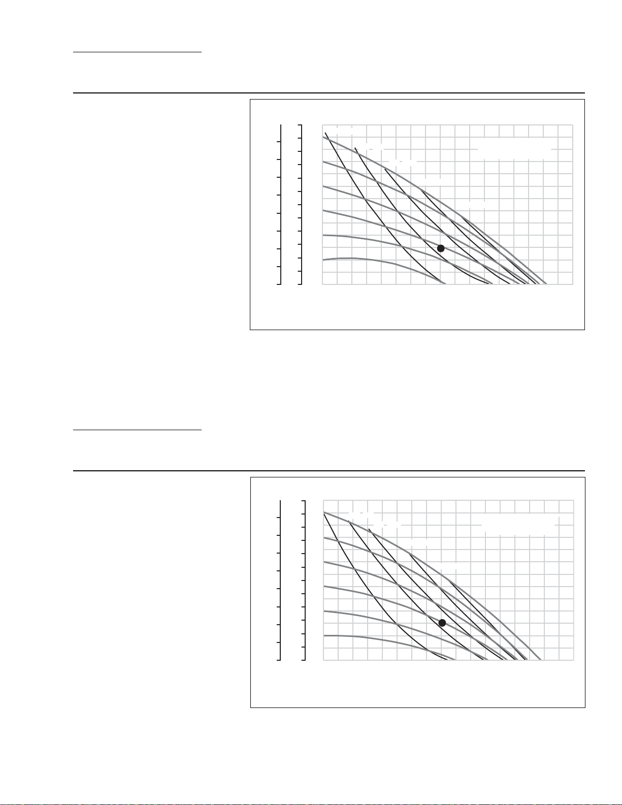
SECTION 5B
PERFORMANCE CURVES
T8 PLASTIC ULTRA-FLEX™-FITTED
Height ..................................770 mm (30.3”)
Width ...................................490 mm (19.3”)
Depth .................................. 333 mm (13.1”)
Est. Ship Weight ........Polypropylene 35 kg (77 lbs)
Air Inlet ....................................19 mm (3/4”)
Inlet ............................................51 mm (2”)
Outlet ......................................... 51 mm (2”)
Suction Lift ........................... 3.4 m Dr y (11’)
9.1 m Wet (30’)
Displacement / Stroke ..... 1.74 l (0.46 gal.)
1
Max. Flow Rate ...............556 lpm (147 gpm)
Max. Size Solids ..................... 6.4 mm (1/4”)
1
Displacement per stroke was calculated at 4.8 bar
(70 psig) air inlet pressure against a 2 bar (30 psig)
head pressure.
Example: To pump 303 lpm (80 gpm) against
a discharge pressure head of 2 bar (30 psig)
requires 4.1 bar (60 psig) and 82 Nm
3
/h (48
scfm) air consumption. (See dot on chart.)
Caution: Do not exceed 8.6 bar (125 psig) air
supply pressure.
BAR
8
7
6
5
4
Discharge Pressure
3
2
1
0
Flow rates indicated on chart were determined by pumping water.
For optimum life and performance, pumps should be specified so that daily operation parameters
will fall in the center of the pump performance curve.
FEET
300
275
250
225
200
175
150
125
100
75
50
25
0
PSIG
120
100
80
60
40
20
GPM
[LPM]
(20) [34]
(40)
[68]
20 40 60 80 100 120 140 160
[76] [151] [227] [303] [378] [454] [530]
(60) [102]
(80) [136]
(100) [170]
Water Discharge Flow Rates
AIR CONSUMPTION
(SCFM) [Nm
3
/h]
[606]
5
WILDEN PUMP & ENGINEERING, LLCWIL-10230-E-02
Page 8
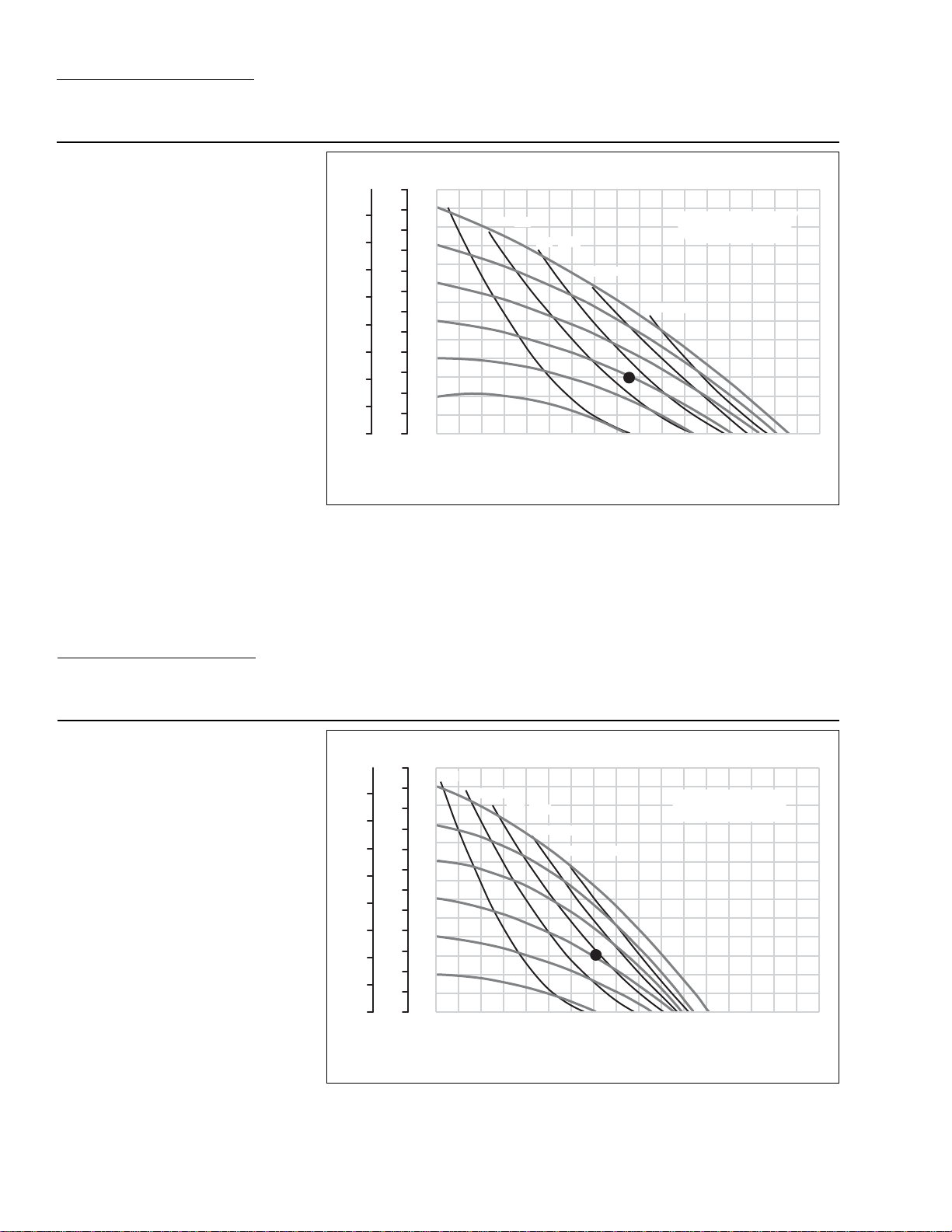
SECTION 5C
PERFORMANCE CURVES
T8 PLASTIC TPE-FITTED
Height ..................................770 mm (30.3”)
Width ...................................490 mm (19.3”)
Depth .................................. 333 mm (13.1”)
Est. Ship Weight ........Polypropylene 35 kg (77 lbs)
Air Inlet ....................................19 mm (3/4”)
Inlet ............................................51 mm (2”)
Outlet ......................................... 51 mm (2”)
Suction Lift ........................... 4.6 m Dr y (15’)
9.5 m Wet (31’)
Displacement / Stroke ..... 2.91 l (0.77 gal.)
1
Max. Flow Rate ...............591 lpm (156 gpm)
Max. Size Solids ..................... 6.4 mm (1/4”)
1
Displacement per stroke was calculated at 4.8 bar
(70 psig) air inlet pressure against a 2 bar (30 psig)
head pressure.
Example: To pump 322 lpm (85 gpm) against
a discharge pressure head of 2 bar (30 psig)
requires 4.1 bar (60 psig) and 85 Nm
3
/h (50
scfm) air consumption. (See dot on chart.)
Caution: Do not exceed 8.6 bar (125 psig) air
supply pressure.
BAR
FEET
300
275
8
250
7
225
6
200
175
5
150
4
125
Discharge Pressure
3
100
75
2
50
1
25
0
0
Flow rates indicated on chart were determined by pumping water.
For optimum life and performance, pumps should be specified so that daily operation parameters
will fall in the center of the pump performance curve.
PSIG
120
100
80
60
40
20
GPM
[LPM]
(20) [34]
(40) [68]
(60) [102]
(80) [136]
AIR CONSUMPTION
(SCFM) [Nm
(100) [170]
20 40 60 80 100 120 140 160
[76] [151] [227] [303] [378] [454] [530]
Water Discharge Flow Rates
3
/h]
[606]
SECTION 5D
PERFORMANCE CURVES
T8 PLASTIC PTFE-FITTED
Height ..................................770 mm (30.3”)
Width ...................................490 mm (19.3”)
Depth .................................. 333 mm (13.1”)
Est. Ship Weight ........Polypropylene 35 kg (77 lbs)
Air Inlet ....................................19 mm (3/4”)
Inlet ............................................51 mm (2”)
Outlet ......................................... 51 mm (2”)
Suction Lift ........................... 3.1 m Dr y (10’)
9.5 m Wet (31’)
Displacement / Stroke ...... 1.51 l (0.40 gal)
1
Max. Flow Rate ...............458 lpm (121 gpm)
Max. Size Solids ..................... 6.4 mm (1/4”)
1
Displacement per stroke was calculated at 4.8 bar
(70 psig) air inlet pressure against a 2 bar (30 psig)
head pressure.
Example: To pump 265 lpm (70 gpm) against
a discharge pressure head of 2 bar (30 psig)
requires 4.1 bar (60 psig) and 93.5 Nm
3
/
h (55 scfm) air consumption. (See dot on
chart.)
Caution: Do not exceed 8.6 bar (125 psig) air
supply pressure.
Flow rates indicated on chart were determined by pumping water.
For optimum life and performance, pumps should be specified so that daily operation parameters
will fall in the center of the pump performance curve.
BAR
e
Discharge Pressur
FEET
300
275
8
250
7
225
6
200
175
5
150
4
125
3
100
75
2
50
1
25
0
0
PSIG
120
100
80
60
40
20
GPM
[LPM]
(20) [34]
(40) [68]
(60)
[102]
(80) [136]
(100) [170]
AIR CONSUMPTION
(SCFM) [Nm
20 40 60 80 100 120 140 160
[76] [151] [227] [303] [378] [454] [530]
Water Discharge Flow Rates
3
/h]
[606]
WILDEN PUMP & ENGINEERING, LLC WIL-10230-E-02
6
Page 9

SECTION 5E
PERFORMANCE CURVES
A8 PLASTIC ACCU-FLO™ RUBBER/TPE-FITTED
Height ..................................770 mm (30.3”)
Width ...................................490 mm (19.3”)
Depth .................................. 333 mm (13.1”)
Est. Ship Weight ........Polypropylene 34 kg (75 lbs)
PVDF 43 kg (95 lbs)
Air Inlet ....................................19 mm (3/4”)
Inlet ............................................51 mm (2”)
Outlet ......................................... 51 mm (2”)
Suction Lift ........................... 6.1 m Dr y (20’)
8.5 m Wet (28’)
Displacement / Stroke ..... 0.55 gal. (2.08 l)
Max. Flow Rate ...............420 lpm (111 gpm)
Max. Size Solids ..................... 6.4 mm (1/4”)
1
Displacement per stroke was calculated at 4.8 bar
(70 psig) air inlet pressure against a 2 bar (30 psig)
head pressure.
Example: To pump 197 lpm (52 gpm) against
a discharge pressure head of 2.7 bar (40 psig)
requires 5.5 bar (80 psig) inlet air pressure,
3
68 Nm
/h (40 scfm) air consumption and a
pump speed of 108 strokes/minute. (See dot
on chart.)
Caution: Do not exceed 8.6 bar (125 psig) air
supply pressure.
1
SECTION 5F
3
/h]
Sec / Stroke
Interval
0.9
0.8
0.7
0.6
0.5
0.4
[606]
[SPM]
[67]
[75]
[86]
[100]
[120]
[150]
Optimal Speed
BAR
FEET
PSIG
300
275
8
250
7
225
e
6
200
175
5
150
4
125
Discharge Pressur
3
100
75
2
50
1
25
0
0
Flow curves are for “optimal speed” conditions only. The “optimal speed” is that speed which
provides the maximum flow under a particular air and fluid pressure condition. The optimal speed
varies for different fluid and air pressures. Recommendations for optimal speed can be found on
the right side of the flow curve.
Flow rates indicated on chart were determined by pumping water.
For optimum life and performance, pumps should be specified so that daily operation parameters
will fall in the center of the pump performance curve.
Note: TPE suction lift is approximately half that of rubber-fitted.
(20) [34]
120
100
80
60
40
20
GPM
[LPM] [76] [151] [227] [303] [378] [454] [530]
(40) [68]
(60) [102]
(80) [136]
20 40 60 80 100 120 140 160
Water Discharge Flow Rates
AIR CONSUMPTION
(SCFM) [Nm
70/30 OPERATING CONDITION
A8 PLASTIC ACCU-FLO™
RUBBER/TPE-FITTED
This curve demonstrates the flow
created when the stroke rate is modified under a static air and fluid pressure condition. This curve can be
applied to different pressure conditions
to estimate the change in flow due to
stroke rate.
A8 Plastic Accu-Flo™ Rubber / TPE-Fitted
SPM
220
200
180
160
140
120
Speed
100
80
60
40
20
0
GPM
[LPM] [114] [151] [189][38] [76] [227] [265]
@ 70 / 30 operating condition
10 20 30 40 50 60 70
Water Discharge Flow Rate
7
WILDEN PUMP & ENGINEERING, LLCWIL-10230-E-02
Page 10
SECTION 5G
A
PERFORMANCE CURVES
A8 PLASTIC ACCU-FLO™ ULTRA-FLEX™/PTFE-FITTED
Height ..................................770 mm (30.3”)
Width ...................................490 mm (19.3”)
Depth .................................. 333 mm (13.1”)
Est. Ship Weight ........Polypropylene 34 kg (75 lbs)
PVDF 43 kg (95 lbs)
Air Inlet ....................................19 mm (3/4”)
Inlet ............................................51 mm (2”)
Outlet ......................................... 51 mm (2”)
Suction Lift ........................... 3.4 m Dr y (11’)
8.5 m Wet (28’)
Displacement / Stroke ..... 1.74 l (0.46 gal.)
Max. Flow Rate ...............386 lpm (102 gpm)
Max. Size Solids ..................... 6.4 mm (1/4”)
1
Displacement per stroke was calculated at 4.8 bar
(70 psig) air inlet pressure against a 2 bar (30 psig)
head pressure.
Example: To pump 189 lpm (50 gpm)
against a discharge pressure head of 2.7 bar
(40 psig) requires 5.5 bar (80 psig) inlet air
pressure, 85 Nm
tion and a pump speed of 120 strokes/minute.
(See dot on chart.)
Caution: Do not exceed 8.6 bar (125 psig) air
supply pressure.
3
/h (50 scfm) air consump-
1
SECTION 5H
PSIG
FEET
BAR
300
275
8
250
7
225
e
6
200
175
5
150
4
125
Discharge Pressur
3
100
75
2
50
1
25
0
0
Flow curves are for “optimal speed” conditions only. The “optimal speed” is that speed which
provides the maximum flow under a particular air and fluid pressure condition. The optimal speed
varies for different fluid and air pressures. Recommendations for optimal speed can be found on
the right side of the flow curve.
Flow rates indicated on chart were determined by pumping water.
For optimum life and performance, pumps should be specified so that daily operation parameters
will fall in the center of the pump performance curve.
(20) [34]
120
100
80
60
40
20
GPM
[ LPM] [76] [151] [227] [303] [378] [454] [530]
(40) [68]
(60) [102]
(80) [136]
20 40 60 80 100 120 140 160
Water Discharge Flow Rates
Sec / Stroke
Interval
0.9
0.8
0.7
0.6
0.5
0.4
0.3
[606]
[SPM]
[67]
[75]
[86]
[100]
[120]
[150]
[200]
Optimal Speed
70/30 OPERATING CONDITION
A8 PLASTIC ACCU-FLO™
ULTRA-FLEX™-PTFE-FITTED
This curve demonstrates the flow
created when the stroke rate is modified under a static air and fluid pressure condition. This curve can be
applied to different pressure conditions
to estimate the change in flow due to
stroke rate.
8 Plastic Accu-Flo™ Ultra-Flex™/PTFE-Fitted
SPM
220
200
180
160
140
120
Speed
100
80
60
40
20
0
GPM
[LPM]
@ 70 / 30 operating condition
10 20 30 40 50 60 70
[114] [151] [189][38] [76] [227] [265]
Water Discharge Flow Rate
WILDEN PUMP & ENGINEERING, LLC WIL-10230-E-02
8
Page 11

SECTION 6A
SUCTION LIFT CURVES & DATA
T8 Plastic Suction Lift Capability
O
FT H
Meter
7
6
5
4
Dry Vacuum
3
2
1
0
PSIG
[BAR] [0.7] [1.4] [2.0] [2.7] [3.4] [4.1] [4.8] [5.5] [6.2] [6.9]
2
26
24
22
20
18
TPE
Diaphragms
Rubber Diaphragms
16
14
PTFE Diaphragms
12
10
8
6
Ultra-Flex™
Diaphragms
4
2
0
0 102030405060708090100
Inlet Air Pressure
Suction lift curves are calibrated for pumps operating at
305 m (1,000’) above sea level. This chart is meant to be
a guide only. There are many variables which can affect
your pump’s operating characteristics. The number of intake
and discharge elbows, viscosity of pumping fluid, elevation
(atmospheric pressure) and pipe friction loss all affect the
amount of suction lift your pump will attain.
SECTION 6B
SUCTION LIFT CURVES & DATA
A8 Plastic Accu-Flo™ Suction Lift Capability
O
FT H
Meter
7
6
5
4
Dry Vacuum
3
2
1
0
PSIG
[BAR] [0.7] [1.4] [2.0] [2.7] [3.4] [4.1] [4.8] [5.5] [6.2] [6.9]
Suction lift curves are calibrated for pumps operating at
305 m (1,000’) above sea level. This chart is meant to be
a guide only. There are many variables which can affect
your pump’s operating characteristics. The number of intake
2
26
24
22
20
18
16
Ultra-Flex™ /
14
Diaphragms
PTFE
12
10
8
6
Rubber / TPE
4
Diaphragms
2
0
0 102030405060708090100
Inlet Air Pressure
The solenoid was running at 150 strokes / minute.
Actual suction lift may vary with different pump speeds.
and discharge elbows, viscosity of pumping fluid, elevation
(atmospheric pressure) and pipe friction loss all affect the
amount of suction lift your pump will attain.
9
WILDEN PUMP & ENGINEERING, LLCWIL-10230-E-02
Page 12

SECTION 7A
INSTALLATION – T8 PLASTIC
AIR-OPERATED PUMPS
The Model T8 plastic pump has a 51 mm (2”) inlet and 51 mm
(2”) outlet and is designed for flows to 591 lpm (156 gpm).
The T8 plastic pump is manufactured with wetted parts of
polypropylene. The center block of the T8 is constructed of
glass-filled polypropylene. A variety of diaphragms, valve
balls, valve seats, and o-rings are available to satisfy temperature, chemical compatibility, abrasion and flex concerns.
The suction pipe size should be at least 51 mm (2”) diameter or larger if highly viscous material is being pumped.
The suction hose must be non-collapsible, reinforced type
as the T8 is capable of pulling a high vacuum. Discharge
piping should be at least 51 mm (2”); larger diameter can
be used to reduce friction losses. It is critical that all fittings
and connections are airtight or a reduction or loss of pump
suction capability will result.
For T8 plastic models, Wilden offers 68 kg (150 lb.) standard
or metric flanges. The following details should be noted
when mating these to piping:
• A 60–80 shore gasket that covers the entire flange face
should be used.
• The gasket should be between .075” and .175” thickness.
• Mating flanges with flat as opposed to raised surfaces
should be used for proper mechanical sealing.
• The flanges should be tightened to a minimum of 6.8 N•m
(5 ft-lbs) but no more than 13.6 N•m (10 ft-lbs).
A non-raised surfaced-flange adapter should be utilized
when mating to the pump’s inlet and discharge manifolds for
proper sealing.
INST ALLATION: Months of careful planning, study, and selection efforts can result in unsatisfactory pump performance if
installation details are left to chance.
Premature failure and long term dissatisfaction can be avoided if
reasonable care is exercised throughout the installation process.
LOCATION: Noise, safety, and other logistical factors usually
dictate that “utility” equipment be situated away from the
production floor . Multiple installations with conflicting requir ements can result in congestion of utility areas, leaving few
choices for siting of additional pumps.
Within the framework of these and other existing conditions,
every pump should be located in such a way that four key factors
are balanced against each other to maximum advantage.
ACCESS: First of all, the location should be accessible. If it’s
easy to reach the pump, maintenance personnel will have an
easier time carrying out routine inspections and adjustments.
Should major repairs become necessary, ease of access can
play a key role in speeding the repair process and reducing
total downtime.
AIR SUPPL Y : Every pump location should have an air line large
enough to supply the volume of air necessary to achieve the
desired pumping rate (see pump performance chart). Use air
pressure up to a maximum of 8.6 bar (125 psig) depending
upon pumping requirements.The use of an air filter before the
pump will ensure that the majority of any pipeline contaminants will be eliminated. For best results, the pumps should
use an air filter, regulator, and lubricator system.
ELEVATION: Selecting a site that is well within the pump’s
suction lift capability will assure that loss-of-prime troubles will be eliminated. In addition, pump efficiency can be
adversely affected if proper attention is not given to elevation
(see pump performance chart).
PIPING: Final determination of the pump site should not
be made until the piping problems of each possible location have been evaluated. The impact of current and future
installations should be considered ahead of time to make
sure that inadvertent restrictions are not created for any
remaining sites.
The best choice possible will be a site involving the shortest
and the straightest hook-up of suction and discharge piping.
Unnecessary elbows, bends, and fittings should be avoided.
Pipe sizes should be selected so as to keep friction losses
within practical limits. All piping should be supported independently of the pump. In addition, it should line up without
placing stress on the pump fittings.
Expansion joints can be installed to aid in absorbing the
forces created by the natural reciprocating action of the
pump. If the pump is to be bolted down to a solid foundation,
a mounting pad placed between the pump and foundation
will assist in minimizing pump vibration. Flexible connections
between the pump and rigid piping will also assist in minimizing pump vibration. If quick-closing valves are installed
at any point in the discharge system, or if pulsation within a
system becomes a problem, a surge suppressor should be
installed to protect the pump, piping and gauges from surges
and water hammer.
When pumps are installed in applications involving flooded
suction or suction head pressures, a gate valve should be
installed in the suction line to permit closing of the line for
pump service.
The T8 can be used in submersible applications only when
both wetted and non-wetted portions are com patible with
the material being pumped. If the pump is to be used in a
submersible application, a hose should be attached to the
pump’s air exhaust and the exhaust air piped above the
liquid level.
If the pump is to be used in a self-priming application, be
sure that all connections are airtight and that the suction lift
is within the pump’s ability. Note: Materials of construction
and elastomer material have an effect on suction lift parameters. Please refer to pump performance data.
Pumps in service with a positive suction head are most efficient when inlet pressure is limited to 0.5–0.7 bar (7–10 psig).
Premature diaphragm failure may occur if positive suction
is 0.8 bar (11 psig) and higher.
THE MODEL T8 WILL PASS 6.4 mm (1/4”) SOLIDS. WHENEVER THE POSSIBILITY EXISTS THAT LARGER SOLID
OBJECTS MAY BE SUCKED INTO THE PUMP, A STRAINER
SHOULD BE USED ON THE SUCTION LINE.
CAUTION: DO NOT EXCEED 8.6 BAR (125 PSIG) AIR
SUPPLY PRESSURE.
BLOW OUT AIR LINE FOR 10 TO 20 SECONDS BEFORE
ATTACHING TO PUMP TO MAKE SURE ALL PIPE LINE
DEBRIS IS CLEAR. ALWAYS USE AN IN-LINE AIR
FILTER.
PUMPS SHOULD BE THOROUGHLY FLUSHED WITH
WATER BEFORE INSTALLING INTO PROCESS LINES.
FDA AND USDA APPROVED PUMPS SHOULD BE
CLEANED AND/OR SANITIZED BEFORE BEING USED
ON EDIBLE PRODUCTS.
WILDEN PUMP & ENGINEERING, LLC WIL-10230-E-02
10
Page 13

SUGGESTED INSTALLATION
AIR OPERATED PUMPS: To stop the pump fr om operating in an emergency situation, simply close the shutoff valve (user supplied) installed in the air supply line.
A properly functioning valve will stop the air supply to
the pump, therefore stopping output. This shut-off valve
should be located far enough away from the pumping
equipment such that it can be reached safely in an
emergency situation.
ACCU-FLO™ PUMPS: Accu-Flo pumps function with
solenoid valves and require an electrical control circuit
to supply pulses. Under normal operating conditions,
the control circuit is sufficient for starting and stopping
the pump. However, the shut-off valve (user supplied)
installed in the air supply line can be used to stop the
NOTE: In the event of a power failure, the shutoff valve should be closed, if the
restarting of the pump is not desirable once power is regained.
pump if necessary. Therefore, it should be located far
enough away from the pumping equipment such that it
can be reached safely in an emergency situation.
®
SECTION 7B – AIR OPERATION
SUGGESTED OPERATION AND
MAINTENANCE INSTRUCTIONS
OPERATION: Pump discharge rate can be controlled by
limiting the volume and/or pressure of the air supply to the
pump (preferred method). An air regulator is used to regulate air pressure. A needle valve is used to regulate volume.
Pump discharge rate can also be controlled by throttling the
pump discharge by partially closing a valve in the discharge
line of the pump. This action increases friction loss which
reduces flow rate. This is useful when the need exists to
control the pump from a remote location. When the pump
discharge pressure equals or exceeds the air supply pressure, the pump will stop; no bypass or pressure relief valve
is needed, and pump damage will not occur. The pump
has reached a “deadhead” situation and can be restarted
by reducing the fluid discharge pressure or increasing the
air inlet pressure. The Wilden T8 pump runs solely on
compressed air and does not generate heat, therefore your
process fluid temperature will not be affected.
RECORDS: When service is required, a record should be
made of all necessary repairs and replacements. Over a
period of time, such records can become a valuable tool
for predicting and preventing future maintenance problems
and unscheduled downtime. In addition, accurate records
make it possible to identify pumps that are poorly suited to
their applications.
MAINTENANCE AND INSPECTIONS: Since each application is unique, maintenance schedules may be different
for every pump. Frequency of use, line pressure, viscosity
and abrasiveness of process fluid all affect the parts life
of a Wilden pump. Periodic inspections have been found
to offer the best means for preventing unscheduled pump
downtime. Personnel familiar with the pump’s construction
and service should be informed of any abnormalities that
are detected during operation.
11
WILDEN PUMP & ENGINEERING, LLCWIL-10230-E-02
Page 14

SECTION 7C
OPERATING PRINCIPLES BEHIND
ACCU-FLO™ PUMPS
In Accu-Flo™ pump models, the standard air valve is replaced
with a two position, four-way solenoid valve that has a single
operator and spring return. The valve is internally air piloted
for longer coil and operator life.
When the solenoid is unpowered, one air chamber is pressurized with air, while the opposite chamber is exhausted.
When electric power is applied, the solenoid shifts, and the
pressurized air chamber is exhausted while the opposite
chamber is pressurized. By alternately applying and removing power, the solenoid-operated pump runs like a standard
Wilden pump.
The speed of the pump is controlled electrically. Since each
stroke is controlled by an electrical signal, the pump is ideal
for batching and other electrically controlled dispensing applications.
Although the speed of the pump is controlled electrically,
the air pressure is important. Air pressure displaces the fluid,
and if the pressure is insufficient to complete the physical
stroke before an electronic impulse signals the pump to shift,
the stroke will not be completed, and the displacement per
stroke will be reduced. This does not harm the unit in any
way, but it may cause inaccuracy when attempting to batch
specific quantities with high precision if this effect is not
taken into account.
There are three coil voltage options available. One coil allows
for 24V DC operation. The second coil option allows for
operation with either 12V DC or 24V AC at 60 Hz and the
third coil option allows for 110V AC operation.
SECTION 7D
INSTALLATION – A8 PLASTIC
ACCU-FLO™ PUMPS
Before installing your A8 Accu-Flo™ pump, review Section
7A for general installation suggestions including Location,
Access, Air Supply, Elevation, and Piping.
The Accu-Flo™ Model A8 has a 51 mm (2”) inlet and 51 mm
(2”) outlet and is designed for flows to 420 lpm (111 gpm).
This maximum flow rate was calculated at 300 strokes per
minute with 100 psig air inlet against 0 psig discharge head.
The A8 Plastic pump is manufactured with wetted parts of
polypropylene or PVDF. The center section of the A8 Plastic pump is of aluminum or polypropylene construction. A
variety of diaphragms, valve balls, and o-rings are available
to satisfy temperature, chemical compatibility, abrasion and
flex concerns.
All wiring used to operate the pump should be placed and
connected according to the proper electrical codes. It is
important that the wiring is of adequate gauge to carry
the current required to operate the pump. In addition, it is
necessary that the electrical power supply is large enough
to supply the current required to operate the pump. Wiring
should be above ground level if possible (in case of fluid
spill or leakage), and all wiring and connections which could
become wet or damp should be made watertight.
If the pump is to be used in a self-priming application, be
sure that all connections are airtight and that the suction lift
is within the pump’s ability. Note: Materials of construction
and elastomer material have an effect on suction lift parameters. Please refer to pump performance data.
Pumps in service with a positive suction head are most efficient when inlet pressure is limited to 0.5–0.7 bar (7–10 psig).
Premature diaphragm failure may occur if positive suction
head is 0.8 bar (11 psig) and higher.
The solenoid valve is rated for continuous duty; however,
stopping on an even number stroke count insures that the
electrical power is off when pump is stopped. This practice is
safer and also eliminates unwanted strokes when the system
is shut down and electrical power is off.
THE MODEL A8 WILL PASS 6.4 mm (1/4”) SOLIDS. WHENEVER THE POSSIBILITY EXISTS THAT LARGER SOLID
OBJECTS MAY BE SUCKED INTO THE PUMP, A STRAINER
SHOULD BE USED ON THE SUCTION LINE.
WARNING: Before installation, consult chart in Section
10B to ensure proper electrical connection.
WARNING: The solenoid valve should not be used in
an area where explosion proof equipment is required
unless NEMA 7 valve is specified.
There are three coil options available in both NEMA 4 and
NEMA 7 ratings. One coil allows for 110V AC operation, one
allows for 24V DC operation, and the third allows for either
24V AC or 12V DC operation. See Section 10B for options
and part numbers.
WILDEN PUMP & ENGINEERING, LLC WIL-10230-E-02
12
Page 15

ACCU-FLO™ ELECTRICAL
CONNECTIONS
COMMON CONNECTION
*
POWER
*
SUPPLY
FLICKER MODE RELAY OR BATCH CONTROLLER
*
SWITCHED (CONTROL) CONNECTION
*
GROUND (SAFETY) CONNECTION
*
REPEAT
CYCLE
TIMER
RELAY
ACCU-FLO™ PLUMBING
CONNECTIONS
COMBINATION FILTER AND REGULATOR
FLUID OUTLET
AIR SUPPLY
SUCTION LINE
INTAKE
SHUTOFF VALVE
FLEXIBLE
CONNECTION
FLEXIBLE CONNECTION
AIR INLET
FLUID INLET
FLEXIBLE CONNECTION
SECTION 7E – ACCU-FLO™
SUGGESTED OPERATION AND
MAINTENANCE INSTRUCTIONS
OPERA TION: The speed of the pump is controlled electrically .
Since each stroke is controlled by an electrical signal, the
pump is ideal for batching and other electrically controlled
dispensing applications.
Although the speed of the pump is controlled electrically,
the air pressure is important. Air pressure displaces the fluid,
and if the pressure is insufficient to complete the physical
stroke before an electronic impulse signals the pump to shift,
the stroke will not be completed, and the displacement per
stroke will be reduced. This does not harm the unit in any
way, but it may cause inaccuracy when attempting to batch
specific quantities with high precision.
The solenoid operated pump is permanently lubricated during
assembly, and requires no additional lubrication under normal
operation. If the unit runs under extreme conditions (continuous operation at high speeds), it may be necessary to relubricate the center block with a buna-N compatible NLGI Grade
2 grease every 50 million cycles. Continuous lubrication with a
compatible oil is not harmful, and will provide longer seal life,
but it may flush all grease out of the unit.
A red button on the side of the air valve is a manual override; when actuated it will shift the valve as if an electric
current had actuated the solenoid.
RECORDS: When service is required, a record should be
made of all necessary repairs and replacements. Over a
period of time, such records can become a valuable tool for
predicting and preventing future maintenance problems and
unscheduled downtime. In addition, accurate records make
it possible to identify pumps that are poorly suited to their
applications.
MAINTENANCE AND INSPECTIONS: Since each application
is unique, maintenance schedules may be different for every
pump. Frequency of use, line pressure, viscosity and abrasiveness of process fluid all affect the parts life of a Wilden pump.
Periodic inspections have been found to offer the best means
for preventing unscheduled pump downtime. Personnel
familiar with the pump’s construction and service should be
informed of any abnormalities that are detected during operation. Internal maintenance is not recommended for Accu-Flo™
solenoid air valves. When worn or damaged, a new air valve
body, coil or terminal connector must be purchased. Please
consult section 9C for part numbers.
13
DISCHARGE
SHUTOFF VALVE
WILDEN PUMP & ENGINEERING, LLCWIL-10230-E-02
DISCHARGE LINE
Page 16

SECTION 7F – AIR-CONTROLLED
TROUBLESHOOTING
Pump will not run or runs slowly.
1. Check air inlet screen and air filter for debris.
2. Check for sticking air valve, flush air valve in solvent.
3. Check for worn out air valve. If piston face in air valve
is shiny instead of dull, air valve is probably worn
beyond working tolerances and must be replaced.
4. Check center block Glyd™ rings. If worn excessively,
they will not seal and air will simply flow through pump
and out air exhaust. Use only Wilden Glyd™ rings as
they are of special construction.
5. Check for rotating piston in air valve.
6. Check type of lubricant being used. A higher viscosity
oil than suggested may cause the piston to stick or run
erratically. Wilden suggests the use of an oil with arctic
characteristics (ISO 15-5 wt.).
Pump runs but little or no product flows.
1. Check for pump cavitation; slow pump speed down
to match thickness of material being pumped.
2. Check for sticking ball check valves. If material
being pumped is not compatible with pump elastomers,
SECTION 7G – ACCU-FLO™
TROUBLESHOOTING
swelling may occur. Replace ball check valves and orings with the proper elastomers.
3. Check to make sure all suction connections are air
tight, especially clamp bands around intake balls.
Pump air valve freezes.
Check for excessive moisture in compressed air. Either
install dryer or hot air generator for compressed air.
Air bubbles in pump discharge.
1. Check for ruptured diaphragm.
2. Check tightness of clamp bands, especially at intake
manifold.
Product comes out air exhaust.
1. Check for diaphragm rupture.
2. Check tightness of piston plates to shaft.
Pump rattles.
1. Create false discharge head or suction lift.
Pump will not run.
1. Check for pressurized air at the inlet. (3.1 bar [Min. 45
psig].)
2. Check air inlet and filter for debris.
3. Connect a test lamp to the two wires which run to
pump and ensure that the lamp cycles on and off.
4. Make sure that the air valve manual override (small red
knob on front of valve) is switched to the “0” position.
5. Check pilot pressure vent at the top of the operator/
coil assembly to ensure that it is not clogged.
6. Check for a worn out air valve. If air continually blows
out the exhaust in very large quantities, the air valve
seals may be worn beyond their ability to function. In
this case, the valve must be replaced.
NOTE: Before the valve is scrapped, it is possible that
it may be saved by completely disassembling the
valve, cleaning all components and relubricating the
valve.
Pump runs but little or no fluid comes out.
1. Check that the discharge isolation valve is not closed.
2. Check that the electronic signal is slow enough that the
pump is able to complete each physical stroke before
it is signaled to change direction. The time required to
complete the stroke is determined by a variety of
factors which include fluid viscosity and head pressure. The shaft can be viewed if the muffler is removed
to verify that the pump is stroking.
3. Check for pump cavitation; slow pump speed down
to match the thickness of the material being pumped.
4. Check for sticking ball check valves. If the material
being pumped is not compatible with the pump elastomers, swelling may occur. Replace ball check valves
and o-ring with the proper elastomers.
5. Check to make sure that all suction connections are
air tight, and that the clamp bands are properly tightened.
WILDEN PUMP & ENGINEERING, LLC WIL-10230-E-02
Pump air passages blocked with ice.
Check for excessive moisture in compressed air line. As
the air expands out the exhaust during the operation of the
pump, water vapor entrapped in the compressed air can
freeze and block the air passageways in the pump. If this
occurs, it may be necessary to install a coalescing filter , an
air dryer, or a hot air generator for the compressed air.
Air bubbles in pump discharge.
1. Check for ruptured diaphragm.
2. Check tightness of clamp bands, and the integrity of the
o-rings, especially at intake manifold.
Product comes out air exhaust.
1. Check for diaphragm rupture.
2. Check tightness of piston plates to shaft.
Pump rattles.
1. Create false discharge head or suction lift.
Solenoid buzzes or solenoid burnout.
1. Incorrect voltage, faulty or dirty solenoid.
Solenoid valve fails to shift electrically but shifts with
manual override.
1. Incorrect voltage, defective coil or wiring.
Solenoid valve fails to shift electrically or with manual override.
1. Inadequate air supply, contamination, inadequate or
improper lubrication, mechanical binding in the valve.
Valve shifts but fails to return.
1. Broken spring, mechanical binding.
Excessive leaking from air valve vent.
1. Worn seals in air valve.
14
Page 17

SECTION 8A
T8 PLASTIC
DIRECTIONS FOR DISASSEMBLY/REASSEMBLY
CAUTION: Before any maintenance or repair is attempted,
the compressed air line to the pump should be disconnected
and all air pressure allowed to bleed from the pump. Disconnect all intake, discharge, and air lines. Drain the pump by
turning it upside down and allowing any fluid to flow into
a suitable container. Be aware of any hazardous effects of
contact with your process fluid.
The Wilden model T8 plastic has a 51 mm (2”) inlet and outlet
and is designed for flows up to 591 lpm (156 gpm). The
model T8 plastic is available in polypropylene wetted parts.
The air valve is manufactured of brass, PTFE-coated brass,
nickel-plated brass or Stainless Steel. All o-rings used in the
pump are of a special material and shore hardness which
should only be replaced with factory-supplied parts.
TOOLS REQUIRED:
13 mm (1/2”) Wrench
17 mm (11/16”) Socket Wrench
Adjustable Wrench
Vise equipped with soft jaws (such as plywood, plastic
or other suitable material)
NOTE: The model used for these instructions incorporates
rubber diaphragms, balls, and seats. Models with PTFE
diaphragms, balls and seats are the same except where
noted. The procedures for the A8 Accu-Flo™ pump are the
same except for the air distribution system.
DISASSEMBLY:
Step 1.
Before starting disassembly, mark a line from each liquid
chamber to its corresponding air chamber . This line will assist
in proper alignment during reassembly.
Figure 1
Step 2. Figure 2
Utilizing a 13 mm (1/2”) wrench, remove the two small clamp
bands that fasten the discharge manifold to the liquid chambers.
Step 3. Figure 3
Lift away the discharge manifold to expose the valve ball
guide bushings and seats.
15
WILDEN PUMP & ENGINEERING, LLCWIL-10230-E-02
Page 18

Step 4. Figure 4
Remove the discharge valve balls, seats from atop the
liquid chambers and inspect for nicks, gouges, chemical
attack or abrasive wear. Replace worn parts with genuine
Wilden parts for reliable performance.
Step 5. Figure 5
Remove the two small clamp bands, which fasten the intake
manifold to the liquid chambers, and lift away the intake
manifold to expose intake valve balls and seats.
Step 6. Figure 6
Inspect ball guide bushing, ball, seat
and o-ring for nicks, gouges, chemical
attack or abrasive wear. Replace worn
Step 7. Figure 7
If necessary remove small manifold clamp
bands to inspect manifold o-rings.
Step 8. Figure 8
Remove one set of large clamp bands,
which secure one liquid chamber to the
center section.
parts with genuine Wilden parts for reliable performance.
WILDEN PUMP & ENGINEERING, LLC WIL-10230-E-02
16
Page 19

Step 9. Figure 9
Lift liquid chamber away from center section expose
diaphragm and outer piston.
Step 10. Figure 10
Using an adjustable wrench, or by rotating the diaphragm by
hand, remove the diaphragm assembly.
Step 11A. Figure 11A
NOTE: Due to varying torque values,
one of the following two situations may
occur: 1) The outer piston, diaphragm
and inner piston remain attached to the
shaft and the entire assembly can be
removed from the center section.
Step 11B. Figure 11B
2) The outer piston, diaphragm and inner
piston separate from the shaft which
remains connected to the opposite side
diaphragm assembly. Repeat disassembly instructions for the opposite liquid
chamber. Inspect diaphragm assembly
and shaft for signs of wear or chemical attack. Replace all worn parts with
genuine Wilden parts for reliable performance.
17
Step 12. Figure 12
To remove the diaphragm assembly
from the shaft, secure shaft with soft
jaws (a vise fitted with plywood or other
suitable material) to ensure shaft is not
nicked, scratched, or gouged. Using an
adjustable wrench, remove diaphragm
assembly from shaft. Inspect all parts for
wear and replace with genuine Wilden
parts if necessary.
WILDEN PUMP & ENGINEERING, LLCWIL-10230-E-02
Page 20

SECTION 8B
AIR VALVE / CENTER BLOCK
DISASSEMBLY
The air valve assembly consists of both the air valve body
and piston and the center block. The unique design of the
air valve relies only on differential pressure to effect the
diaphragm shift. It is reliable and simple to maintain. The
bushing in the center block, along with the diaphragm shaft,
provides the “trigger” to tell the air valve to shift. The following procedure will ensure that the air valve on your Wilden
pump will provide long trouble-free service.
AIR VALVE BODY AND PISTON
ASSEMBLY AND DISASSEMBLY:
The air valve body and piston can be disconnected from the
pump by removing the four socket head cap screws which
attach it to the center block. The piston in the air valve is
aluminum with a dark gray anodized coating. The piston
should move freely and the ports in the piston should line up
with the ports on the face of the air valve body (see below).
The piston should also appear to be a dull, dark gray in color .
If the piston appears to be a shiny aluminum color, the air
valve is probably worn beyond working tolerance and should
be replaced.
If the piston does not move freely in the air valve, the entire
air valve should be immersed in a cleaning solution.
[NOTE: Do not force the piston by inserting a metal object.]
This soaking should remove any accumulation of sludge
and grit which is preventing the air valve piston from moving
freely. Also, remove and clean the air valve screen. If the air
valve piston does not move freely after the above cleaning,
the air valve should be disassembled as follows: remove the
snap ring from the top end of the air valve cylinder and apply
an air jet to the 3/16-inch hole on the opposite end of the
air valve face. (See Figure C.) CAUTION: The air valve end
cap may come out with considerable force. Hand protection
such as a padded glove or rag should be used to capture
the end cap.
Figure C
Figure D
WILDEN PUMP & ENGINEERING, LLC WIL-10230-E-02
18
Page 21

Small nicks can usually be dressed out and the piston
returned to service. Make sure that the guide pin is straight
and smooth or the piston will not move freely in the cylinder . Clean out anti-centering pin holes located at each side
of the piston. Pin holes are located on each side of the
annular groove on the top of the piston and travel to each
end. New o-rings should be installed on the end caps.
Lubricate the o-rings and install the end caps, assuring
that proper alignment of the piston and cylinder ports is
maintained. (See Figure D). Reinstall air valve to center
block of pump. Tighten per the torque specifications in
Section 8D (page 21).
GLYD™ RING REPLACEMENT:
When the Glyd™ rings become worn, they will no longer
seal and must be replaced. Due to the design characteristics of the Glyd™ rings, it is suggested that you use the
Ringer Seal installation kit when replacing Glyd™ rings.
Consult EOM-Ringer for installation instructions.
CENTER BLOCK ASSEMBLY:
The pump’s center block consists of a polypr opylene or die
cast housing with a cast-in bronze bushing. The bushing
has eleven grooves cut on the inside diameter. There are
seven Glyd™ rings that fit in these grooves (see Figure E).
Since these Glyd™ rings form a part of the shifting function of the pump, it is necessary that they be located in
the proper grooves. The bronze bushing is replaceable in
cast iron or stainless steel center blocks only. When bushing wear becomes excessive, a new center block must be
used.
P/N 08-3300-07 Bronze
Bushing can be pressed
into a stainless steel or
cast iron center section.
(See Figure F). When
installing a new bushing, four bleeder holes
which allow the pump to
exhaust air must be drilled.
(See Figure G).
Figure F (Side View)
4.8 mm (3/16”)
DRILL
BLEED-OFF
PORT
4.0 mm (5/32”)
DRILL
BLEED-OFF
PORT
Grooves in
bushing which
contain Glyd™ rings
Figure E
P/N 08-3210-55-225
4.8 mm (3/16”)
DRILL
BLEED-OFF
PORT
Figure G
Center Block
(Front View)
P/N 08-3800-03-07
19
WILDEN PUMP & ENGINEERING, LLCWIL-10230-E-02
Page 22

SECTION 8C
REASSEMBLY HINTS & TIPS
ASSEMBLY:
Upon performing applicable maintenance to the air distribution system, the pump can now be reassembled. Please
refer to the disassembly instructions for photos and parts
placement. To reassemble the pump, follow the disassembly instructions in reverse order. The air distribution system
needs to be assembled first, then the diaphragms and finally
the wetted path. Please find the applicable torque specifications on this page. The following tips will assist in the
assembly process.
• Clean the inside of the center section shaft bushing to
ensure no damage is done to new seals.
• Stainless bolts should be lubed to reduce the possibility
of seizing during tightening.
MAXIMUM TORQUE SPECIFICATIONS
Description of Part Plastic Pumps
Air Valve 6.8 N•m (60 in-lbs)
Outer Piston (PTFE-fi tted) 81.3 N•m (58 ft-lbs)
Outer Piston (Rubber-fi tted) 81.3 N•m (58 ft-lbs)
Small Clamp Band (All) 6.2 N•m (55 in-lbs)
Medium Clamp Band 10.2 N•m (90 in-lbs)
Large Clamp Band (All) 40.0 N•m (28 ft-lbs)
Center Block Assembly 47.5 N•m (35 ft-lbs)
• Ensure proper alignment on the sealing surfaces of intake
and discharge manifolds.
• Liquid chambers are easier to attach when the diaphragm
is inverted. Prior to attaching the second water chamber,
push diaphragm assembly so that it is as close as possible to the center section.
• PVDF and PFA pumps require PTFE gasket kits for
improved sealing. Gasket kits may be installed on other
pumps where sealing is an issue.
• When assembling PTFE-coated hardware, care should
be taken to keep the coating intact.
• When installing Glyd™ rings, the use of the Wilden Ringer
tool simplifies seal installation.
WILDEN PUMP & ENGINEERING, LLC WIL-10230-E-02
20
Page 23

SECTION 8D
GASKET KIT INSTALLATION
Only PTFE-fitted T8 PVDF and polypropylene pumps come
standard with expanded PTFE Gasket Kits (P/N 08-950399 for PVDF and 08-9502-99 for polypropylene). Carefully
prepare sealing surfaces by removing all debris and foreign
PVDF AND POLYPROPYLENE
Step 1. Figure 1
Gently remove the adhesive covering
from the back of the PTFE tape. Ensure
that the adhesive strip remains attached
to the PTFE tape.
PVDF
Step 2. Figure 2
Starting at any point, place the PTFE
tape in the center of the diaphragm
bead groove on the liquid chamber and
press lightly on the tape to ensure that
the adhesive holds it in place during
assembly. Do not stretch the tape during
placement in center of diaphragm bead
groove.
matter from diaphragm bead and all mating surfaces. If necessary, smooth or deburr all sealing surfaces. Mating surfaces
must be properly aligned in order to ensure positive sealing
characteristics.
Step 3. Figure 3
The ends of the tape should overlap
approximately 13 mm (1/2”). Proceed to
install the PTFE tape on the remaining
liquid chamber.
Step 4. Figure 4
Carefully remove the protective covering from the back of
the PTFE gasket attached to tape.
Step 6. Figure 6
Center the gasket so that it evenly covers the o-ring and
seat areas.
Step 5. Figure 5
Install the valve ball, valve seat and o-ring.
Step 7. Figure 7
Gently apply pressure to gasket to ensure the adhesive maintains a positive seal to stay in place during pump assembly.
21
WILDEN PUMP & ENGINEERING, LLCWIL-10230-E-02
Page 24

SECTION 9A
EXPLODED VIEW/PARTS LISTING
T8
PLASTIC
AIR-
CONTROLLED
WILDEN PUMP & ENGINEERING, LLC WIL-10230-E-02
22
Page 25

T8 PLASTIC RUBBER/TPE-FITTED
Item Part Description Qty.
1 Air Valve Assembly
1
T8/PKAPB
P/N
1 08-2000-07 08-2000-07 08-2000-07 08-2000-05
T8/PKSSB
P/N
T8/PKWPB
P/N
T8/PKCPC/0502
P/N
2 Air Valve Screen 1 08-2500-07 08-2500-07 08-2500-07 08-2500-07
3 Air Valve End Cap w/Guide (Top) 1 08-2300-23 08-2300-23 08-2300-23 08-2300-23
4 Air Valve End Cap w/o Guide (Bottom) 1 08-2330-23 08-2330-23 08-2330-23 08-2330-23
5 End Cap Cover (Not shown) 2 N/R N/R N/R 08-2420-55
6 End Cap Bolt (Not shown) 2 N/R N/R N/R 08-2450-22
7 Air Valve Snap Ring 2 08-2650-03 08-2650-03 08-2650-03 08-2650-03
8 Air Valve Cap O-Ring 2 08-2390-52 08-2390-52 08-2390-52 08-2390-52
9 Oil Bottle (Optional) 1 08-2850-01 08-2850-01 08-2850-01 N/A
10 Plug (Optional) 1 08-7000-07 08-7000-07 08-7000-07 N/A
11 Capillary Rod (Optional) 1 08-2900-99 08-2900-99 08-2900-99 N/A
12 Air Valve Gasket — Buna-N 1 08-2600-52 08-2600-52 08-2600-52 08-2600-52
13 Air Valve Screw 4 08-6000-03 08-6000-03 08-6000-03 08-6000-05
14 Center Block 1 08-3100-20-225 08-3100-20-225 08-3100-20-225 08-3100-20-225
15 Center Block Glyd™ Ring 7 08-3210-55-225 08-3210-55-225 08-3210-55-225 08-3210-55-225
16 Block Gasket — Buna-N 2 08-3520-52 08-3520-52 08-3520-52 08-3520-52
17 Shaft 1 08-3800-09-07 08-3800-09-07 08-3800-09-07 08-3800-09-07
Shaft, Ultra-Flex™ 1 08-3820-03-07 08-3820-03-07 08-3820-03-07 08-3820-03-07
18 Piston, Outer 2 08-4550-21-500 08-4550-21-500 08-4550-21-500 08-4550-21-500
Piston, Outer, Ultra-Flex™ 2 08-4560-21 08-4560-21 08-4560-21 08-4560-21
29 Piston, Inner 2 08-3700-01 08-3700-03 08-3700-01 08-3700-01
Piston, Inner, Ultra-Flex™ 2 04-3700-08 04-3700-08 04-3700-08 04-3700-08
20 Air Chamber, Counter Sunk 2 08-3650-01 08-3650-03 08-3650-02 08-3650-05
21 Air Chamber Screw - 3/8”-16 x 3-9/16” 3 08-6200-08 08-6200-03 08-6200-08 08-6200-03
22 Air Chamber Cone Nut 3/8”-16 3 08-6550-08 08-6550-03 08-6550-08 08-6550-03
23 Liquid Chamber 2 08-5000-20 08-5000-20 08-5000-20 08-5000-20
24 Discharge Elbow 2 08-5230-20 08-5230-20 08-5230-20 08-5230-20
25 Inlet Elbow 2 08-5220-20 08-5220-20 08-5220-20 08-5220-20
26 Manifold T-Section 2 08-5160-20 08-5160-20 08-5160-20 08-5160-20
27 Ball Guide Bushing 4 08-5350-20-500 08-5350-20-500 08-5350-20-500 08-5350-20-500
28 Valve Seat O-Ring* 4 ****
29 Manifold O-Ring* 4 ****
30 Diaphragm* 2 ****
31 Diaphragm, Backup 2 N/A N/A N/A N/A
32 Valve Ball* 4 ****
33 Valve Seat 4 08-1120-20-500 08-1120-20-500 08-1120-20-500 08-1120-20-500
34 Large Clamp Band, Assy. 2 08-7300-03-500 08-7300-03-500 08-7300-03-500 08-7300-05-500
35 Large Carriage Bolt 3/8”-16 x 2-1/2” 4 08-6070-03-500 08-6070-03-500 08-6070-03-500 08-6070-05-500
36 Large Hex Nut 3/8”-16 4 08-6450-03 08-6450-03 08-6450-03 08-6420-05
37 Medium Clamp Band, Assy. 4 08-7200-03-500 08-7200-03-500 08-7200-03-500 08-7200-05-500
38 Medium Carriage Bolt 5/16”-18 x 2-1/4” 8 04-6070-03 04-6070-03 04-6070-03 04-6070-05
39 Medium Hex Nut 5/16”-18 8 08-6400-03 08-6400-03 08-6400-03 08-6400-05
40 Small Clamp Band, Assy. 4 08-7100-03-500 08-7100-03-500 08-7100-03-500 08-7100-05-500
41 Small Carriage Bolt 5/16”-18 x 2” 8 08-6050-03-500 08-6050-03-500 08-6050-03-500 08-6050-05-500
42 Small Square Nut 8 08-6400-03 08-6400-03 08-6400-03 08-6400-05
43 Spacer, Ultra-Flex™ 1 08-3860-08 08-3860-08 08-3860-08 08-3860-08
Muffler (Optional — not shown) 1 08-3510-99 08-3510-99 08-3510-99 08-3510-99
1
Air Valve Assembly includes parts through 08-2390-52 (items 2 through 7). To order pump with oil bottle, add letter D to model #. (Example: T8/AAPD.)
*Refer to corresponding elastomer chart in Section 10.
0502 Specialty Code = PTFE-Coated Hardware
All boldface items are primary wear parts.
23
WILDEN PUMP & ENGINEERING, LLCWIL-10230-E-02
Page 26

SECTION 9B
EXPLODED VIEW/PARTS LISTING
T8
PLASTIC
PTFE-
FITTED
WILDEN PUMP & ENGINEERING, LLC WIL-10230-E-02
24
Page 27

T8 PLASTIC PTFE-FITTED
Item Part Description Qty.
1 Air Valve Assembly
1
T8/PKAPB/
TF/TF/PTV
P/N
1 08-2000-07 08-2000-07 08-2000-07 08-2000-05
T8/PKSSB/
TF/TF/PTV
P/N
T8/PKWPB/
TF/TF/PTV
P/N
T8/PKCPC/
TF/TF/PTV/0502
P/N
2 Air Valve Screen 1 08-2500-07 08-2500-07 08-2500-07 08-2500-07
3 Air Valve End Cap w/Guide (Top) 1 08-2300-23 08-2300-23 08-2300-23 08-2300-23
4 Air Valve End Cap w/o Guide (Bottom) 1 08-2330-23 08-2330-23 08-2330-23 08-2330-23
5 End Cap Cover (Not shown) 2 N/R N/R N/R 08-2420-55
6 End Cap Bolt (Not shown) 2 N/R N/R N/R 08-2450-22
7 Air Valve Snap Ring 2 08-2650-03 08-2650-03 08-2650-03 08-2650-03
8 Air Valve Cap O-Ring 2 08-2390-52 08-2390-52 08-2390-52 08-2390-52
9 Oil Bottle (Optional) 1 08-2850-01 08-2850-01 08-2850-01 N/A
10 Plug (Optional) 1 08-7000-07 08-7000-07 08-7000-07 N/A
11 Capillary Rod (Optional) 1 08-2900-99 08-2900-99 08-2900-99 N/A
12 Air Valve Gasket — Buna-N 1 08-2600-52 08-2600-52 08-2600-52 08-2600-52
13 Air Valve Screw 4 08-6000-03 08-6000-03 08-6000-03 08-6000-05
14 Center Block 1 08-3100-20-225 08-3100-20-225 08-3100-20-225 08-3100-20-225
15 Center Block Glyd™ Ring 7 08-3210-55-225 08-3210-55-225 08-3210-55-225 08-3210-55-225
16 Block Gasket — Buna-N 2 08-3520-52 08-3520-52 08-3520-52 08-3520-52
17 Shaft 1 08-3820-03-07 08-3820-03-07 08-3820-03-07 08-3820-03-07
18 Piston, Outer 2 08-4600-21-500 08-4600-21-500 08-4600-21-500 08-4600-21-500
19 Piston, Inner 2 08-3750-01 08-3750-03 08-3750-01 08-3750-01
20 Air Chamber, Counter Sunk 2 08-3650-01 08-3650-03 08-3650-02 08-3650-05
21 Air Chamber Screw - 3/8”-16 x 3-9/16” 3 08-6200-08 08-6200-03 08-6200-08 08-6200-03
22 Air Chamber Cone Nut 3/8”-16 3 08-6550-08 08-6550-03 08-6550-08 08-6550-03
23 Liquid Chamber 2 08-5000-20 08-5000-20 08-5000-20 08-5000-20
24 Discharge Elbow 2 08-5230-20 08-5230-20 08-5230-20 08-5230-20
25 Inlet Elbow 2 08-5220-20 08-5220-20 08-5220-20 08-5220-20
26 Manifold T-Section 2 08-5160-20 08-5160-20 08-5160-20 08-5160-20
27 Ball Guide Bushing 4 08-5350-20-500 08-5350-20-500 08-5350-20-500 08-5350-20-500
28 Valve Seat O-Ring 4 08-1200-60-500 08-1200-60-500 08-1200-60-500 08-1200-60-500
29 Manifold O-Ring 4 08-1300-60-500 08-1300-60-500 08-1300-60-500 08-1300-60-500
30 Diaphragm 2 08-1010-55 08-1010-55 08-1010-55 08-1010-55
31 Diaphragm, Backup
2
2 08-1060-51 08-1060-51 08-1060-51 08-1060-51
32 Valve Ball 4 08-1080-55 08-1080-55 08-1080-55 08-1080-55
33 Valve Seat 4 08-1120-20-500 08-1120-20-500 08-1120-20-500 08-1120-20-500
34 Large Clamp Band, Assy. 2 08-7300-03-500 08-7300-03-500 08-7300-03-500 08-7300-05-500
35 Large Carriage Bolt 3/8”-16 x 2-1/2” 4 08-6070-03-500 08-6070-03-500 08-6070-03-500 08-6070-05-500
36 Large Hex Nut 3/8”-16 4 08-6450-03 08-6450-03 08-6450-03 08-6420-05
37 Medium Clamp Band, Assy. 4 08-7200-03-500 08-7200-03-500 08-7200-03-500 08-7200-05-500
38 Medium Carriage Bolt 5/16”-18 x 2-1/4” 8 04-6070-03 04-6070-03 04-6070-03 04-6070-05
49 Medium Hex Nut 5/16”-18 8 08-6400-03 08-6400-03 08-6400-03 08-6400-05
40 Small Clamp Band, Assy. 4 08-7100-03-500 08-7100-03-500 08-7100-03-500 08-7100-05-500
41 Small Hex Head Cap Screw 5/16”-18 x 2” 8 08-6050-03-500 08-6050-03-500 08-6050-03-500 08-6050-05-500
42 Small Square Nut 8 08-6400-03 08-6400-03 08-6400-03 08-6400-05
Muffler (Optional — not shown) 1 08-3510-99 08-3510-99 08-3510-99 08-3510-99
1
Air Valve Assembly includes parts through 08-2390-52 (items 2 through 7). To order pump with oil bottle, add letter D to model #. (Example: T8/AAPD.)
2
PTFE diaphragm, P/N 08-1010-55, must be used with Neoprene back-up diaphragms, P/N 08-1060-51.
0502 Specialty Code = PTFE-Coated Hardware
All boldface items are primary wear parts.
25
WILDEN PUMP & ENGINEERING, LLCWIL-10230-E-02
Page 28

SECTION 9C
EXPLODED VIEW/PARTS LISTING
A8
PLASTIC
ACCU-FLO™
WILDEN PUMP & ENGINEERING, LLC WIL-10230-E-02
26
Page 29

A8 PLASTIC ACCU-FLO™ Rubber-Fitted PTFE-Fitted
A8/
Item Part Description Qty.
1 Solenoid Valve Assembly
1
2 Main Valve Body 1
3 Coil 1
4 Terminal Connector 1
5 Operator 1
6 Air Valve Gasket — Buna-N 1
7 Air Valve Screw 4
8 Center Block 1
9 Center Block Glyd™ Ring 7
10 Block Gasket — Buna-N 2
11 Shaft, Rubber/TPE 1
Shaft, Ultra-Flex™/PTFE 1
12 Piston, Outer 2
Piston, Outer, Ultra-Flex™ 2
13 Piston, Inner 2
Piston, Inner, Ultra-Flex™ 2
14 Air Chamber, Counter Sunk 2
15 Air Chamber Screw - 3/8”-16 x 3-9/16” 3
16 Air Chamber Cone Nut 3/8”-16 3
17 Liquid Chamber 2
18 Discharge Elbow 2
19 Inlet Elbow 2
20 Manifold T-Section 2
21 Ball Guide Bushing 4
22 Valve Seat O-Ring* 4
23 Manifold O-Ring* 4
24 Diaphragm* 2
25 Diaphragm, Backup 2
26 Valve Ball* 4
27 Valve Seat 4
28 Large Clamp Band 2
29 Large Carriage Bolt 3/8”-16 x 2-1/2” 4
30 Large Hex Nut 3/8”-16 4
31 Medium Clamp Band 4
32 Medium Carriage Bolt 5/16”-18 x 2-1/4” 8
33 Medium Hex Nut 5/16”-18 8
34 Small Clamp Band 4
35 Small Hex Head Cap Screw 5/16”-18 x 1-3/4” 8
36 Small Square Nut 8
Muffler (Optional — not shown) 1
37 Spacer, Ultra-Flex™ 1
38 Bumper Pad 2
1
Solenoid Assembly includes items 2, 3, and 4.
PKAPA/0150
P/N
1 08-2000-99-150 08-2000-99-150 08-2000-99-150 08-2000-99-150 08-2000-99-150 08-2000-99-150 08-2000-99-150 08-2000-99-150
08-2000-01-150 08-2000-01-150 08-2000-01-150 08-2000-01-150 08-2000-01-150 08-2000-01-150 08-2000-01-150 08-2000-01-150
00-2110-99-150 00-2110-99-150 00-2110-99-150 00-2110-99-150 00-2110-99-150 00-2110-99-150 00-2110-99-150 00-2110-99-150
00-2130-99 00-2130-99 00-2130-99 00-2130-99 00-2130-99 00-2130-99 00-2130-99 00-2130-99
00-2120-99 00-2120-99 00-2120-99 00-2120-99 00-2120-99 00-2120-99 00-2120-99 00-2120-99
08-2600-52 08-2600-52 08-2600-52 08-2600-52 08-2600-52 08-2600-52 08-2600-52 08-2600-52
08-6000-03 08-6000-03 08-6000-03 08-6000-03 08-6000-03 08-6000-03 08-6000-03 08-6000-03
08-3100-20-225 08-3100-03-225 08-3100-20-225 08-3100-03-225 08-3100-20-225 08-3100-03-225 08-3100-20-225 08-3100-03-225
08-3210-55-225 08-3210-55-225 08-3210-55-225 08-3210-55-225 08-3210-55-225 08-3210-55-225 08-3210-55-225 08-3210-55-225
08-3520-52 08-3520-52 08-3520-52 08-3520-52 08-3520-52 08-3520-52 08-3520-52 08-3520-52
08-3805-09 08-3805-09 08-3805-09 08-3805-09 N/A N/A N/A N/A
08-3840-09 08-3840-09 08-3840-09 08-3840-09 08-3840-09 08-3840-09 08-3840-09 08-3840-09
08-4550-21-500 08-4550-21-500 08-4550-21-500 08-4550-21-500 08-4600-21-500 08-4600-21-500 08-4600-21-500 08-4600-21-500
08-4560-21 08-4560-21 08-4560-21 08-4560-21 N/A N/A N/A N/A
08-3700-01 08-3700-03 08-3700-01 08-3700-03 08-3750-01 08-3750-03 08-3750-01 08-3750-03
04-3700-08 04-3700-08 04-3700-08 04-3700-08 N/A N/A N/A N/A
08-3650-01 08-3650-03 08-3650-01 08-3650-03 08-3650-01 08-3650-03 08-3650-01 08-3650-03
08-6200-08 08-6200-03 08-6200-08 08-6200-03 08-6200-08 08-6200-03 08-6200-08 08-6200-03
08-6550-08 08-6550-03 08-6550-08 08-6550-03 08-6550-08 08-6550-03 08-6550-08 08-6550-03
08-5000-20 08-5000-20 08-5000-21 08-5000-21 08-5000-20 08-5000-20 08-5000-21 08-5000-21
08-5230-20 08-5230-20 08-5230-21 08-5230-21 08-5230-20 08-5230-20 08-5230-21 08-5230-21
08-5220-20 08-5220-20 08-5220-21 08-5220-21 08-5220-20 08-5220-20 08-5220-21 08-5220-21
08-5160-20 08-5160-20 08-5160-21 08-5160-21 08-5160-20 08-5160-20 08-5160-21 08-5160-21
08-5350-20-500 08-5350-20-500 08-5350-21-500 08-5350-21-500 08-5350-20-500 08-5350-20-500 08-5350-21-500 08-5350-21-500
* * * * 08-1200-59-500 08-1200-59-500 08-1200-60-500 08-1200-60-500
* * * * 08-1300-59-500 08-1300-59-500 08-1300-60-500 08-1300-60-500
* * * * 08-1010-55 08-1010-55 08-1010-55 08-1010-55
N/A N/A N/A N/A 08-1060-51 08-1060-51 08-1060-51 08-1060-51
* * * * 08-1080-55 08-1080-55 08-1080-55 08-1080-55
08-1120-20-500 08-1120-20-500 08-1120-21-500 08-1120-21-500 08-1120-20-500 08-1120-20-500 08-1120-21-500 08-1120-21-500
08-7300-03-500 08-7300-03-500 08-7300-03-500 08-7300-03-500 08-7300-03-500 08-7300-03-500 08-7300-03-500 08-7300-03-500
08-6070-03-500 08-6070-03-500 08-6070-03-500 08-6070-03-500 08-6070-03-500 08-6070-03-500 08-6070-03-500 08-6070-03-500
08-6450-03 08-6450-03 08-6450-03 08-6420-03 08-6450-03 08-6450-03 08-6450-03 08-6450-03
08-7200-03-500 08-7200-03-500 08-7200-03-500 08-7200-03-500 08-7200-03-500 08-7200-03-500 08-7200-03-500 08-7200-03-500
04-6070-03 04-6070-03 04-6070-03 04-6070-03 04-6070-03 04-6070-03 04-6070-03 04-6070-03
08-6400-03 08-6400-03 08-6400-03 08-6400-03 08-6400-03 08-6400-03 08-6400-03 08-6400-03
08-7100-03-500 08-7100-03-500 08-7100-03-500 08-7100-03-500 08-7100-03-500 08-7100-03-500 08-7100-03-500 08-7100-03-500
08-6050-03-500 08-6050-03-500 08-6050-03-500 08-6050-03-500 08-6050-03-500 08-6050-03-500 08-6050-03-500 08-6050-03-500
08-6400-03 08-6400-03 08-6400-03 08-6400-03 08-6400-03 08-6400-03 08-6400-03 08-6400-03
08-3510-99 08-3510-99 08-3510-99 08-3510-99 08-3510-99 08-3510-99 08-3510-99 08-3510-99
08-3860-08 08-3860-08 08-3860-08 08-3860-08 08-3860-08 08-3860-08 08-3860-08 08-3860-08
08-6900-23-50 08-6900-23-50 08-6900-23-50 08-6900-23-50 08-3860-08 08-3860-08 08-6900-23-50 08-6900-23-50
NOTE: Additional solenoid options are available. Please consult Section 10B for electrical reference.
0150 Specialty Code = Solenoid-operated, 24V DC.
* Refer to corresponding elastomer chart in Section 10.
A8/
PKSSA/0150
P/N
A8/
KKAPA/0150
P/N
A8/
KKSSA/0150
P/N
A8/PKAPA/
TF/TF/PTS/0150
P/N
A8/PKSSA/
TF/TF/PTS/0150
P/N
TF/TF/KTV/0150
A8/KKAPA/
P/N
A8/KKSSA/
TF/TF/KTV/0150
P/N
All boldface items are primary wear parts.
27
WILDEN PUMP & ENGINEERING, LLCWIL-10230-E-02
Page 30

SECTION 10A
ELASTOMER OPTIONS
T8 PLASTIC
TRADITIONAL
MATERIAL
Polyurethane 08-1010-50 N/A 08-1200-50-500 08-1300-50-500 08-1080-50
Neoprene 08-1010-51 08-1020-51 N/A N/A 08-1080-51
Buna-N 08-1010-52 08-1020-52 08-1200-52-500 08-1300-52-500 08-1080-52
EPDM 08-1010-54 08-1020-54 N/A N/A 08-1080-54
®
Viton
Sanifl ex™ 08-1010-56 N/A N/A N/A 08-1080-56
PTFE 08-1010-551 N/A N/A N/A 08-1080-55
Tetra-Flex™ PTFE, Neoprene Backed 08-1010-64 N/A N/A N/A N/A
Tetra-Flex™ PTFE, EPDM Backed 08-1010-81 N/A N/A N/A N/A
Neoprene Backup 08-1060-51 N/A N/A N/A N/A
Wil-Flex™ 08-1010-58 N/A N/A N/A 08-1080-58
PTFE Encap. (Viton®) N/A N/A 08-1200-60-500 08-1300-60-500 N/A
NOTES
PTFE-encapsulated Viton® o-rings, P/N 08-1200-60-500 and P/N 08-1300-60-500, are standard on all PTFE-fi tted pumps.
1
PTFE diaphragm, P/N 08-1010-55, must be used with Neoprene back-up diaphragms, P/N 08-1060-51.
DIAPHRAGMS (2)
08-1010-53 08-1020-53 N/A N/A 08-1080-53
ULTRA-FLEX™
DIAPHRAGMS (2)
VALVE SEAT
O-RINGS (4)
MANIFOLD
O-RINGS (4) VALVE BALL (4)
SECTION 10B – ACCU-FLO™
ELECTRICAL REFERENCE
NEMA 4 COIL OPTIONS / UL / CSA (Item 3)
Voltage ±10% Current (A)
AC
DC Power (W) DC Resistivity
Part Number 60 Hz 50 Hz ±10% Inrush Holding (Ω)
00-2110-99-150 24 48 44 4.8 .20 .20 .20 121
00-2110-99-151 12 24 22 4.8 .40 .40 .40 32
00-2110-99-155 60 120 110 4.8 .08 .08 .06 840
NEMA 7 COIL OPTIONS / UL / CSA (Item 3)
Voltage ±10% Current (A)
AC
DC Power (W) DC Resistivity
Part Number 60 Hz 50 Hz ±10% Inrush Holding (Ω)
00-2110-99-153 12 24 22 7 .60 .55 .32 19
00-2110-99-154 24 48 44 7 .30 .30 .18 75
00-2110-99-156 60 120 110 7 .12 .13 .06 475
INTERNATIONAL EXPLOSION PROOF / CENELEC / PTB FILE # EX-91.C.2027
Current (A)
DC Voltage ±10% Power (W) Resistivity
Part Number ±10% Inrush Holding (Ω)
00-2110-99-157 24 3.3 .135 .135 177
AC
AC
OPERATOR OPTIONS (Item 5)
Part Number NEMA Rating
00-2120-99 NEMA 4
00-2121-99 NEMA 7
WILDEN PUMP & ENGINEERING, LLC WIL-10230-E-02
28
Page 31

WARRANTY
Each and every product manufactured by Wilden Pump and Engineering, LLC is built to meet the highest
standards of quality. Every pump is functionally tested to insure integrity of operation.
Wilden Pump and Engineering, LLC warrants that pumps, accessories and parts manufactured or supplied by
it to be free from defects in material and workmanship for a period of five (5) years from date of installation or
six (6) years from date of manufacture, whichever comes first. Failure due to normal wear, misapplication, or
abuse is, of course, excluded from this warranty.
Since the use of Wilden pumps and parts is beyond our control, we cannot guarantee the suitability of any pump
or part for a particular application and Wilden Pump and Engineering, LLC shall not be liable for any consequential
damage or expense arising from the use or misuse of its products on any application. Responsibility is limited
solely to replacement or repair of defective Wilden pumps and parts.
All decisions as to the cause of failure are the sole determination of Wilden Pump and Engineering, LLC.
Prior approval must be obtained from Wilden for return of any items for warranty consideration and must be
accompanied by the appropriate MSDS for the product(s) involved. A Return Goods Tag, obtained from an
authorized Wilden distributor, must be included with the items which must be shipped freight prepaid.
The foregoing warranty is exclusive and in lieu of all other warranties expressed or implied (whether written or oral)
including all implied warranties of merchantability and fitness for any particular purpose. No distributor or other
person is authorized to assume any liability or obligation for Wilden Pump and Engineering, LLC other than expressly
provided herein.
PLEASE PRINT OR TYPE AND FAX TO WILDEN
PUMP INFORMATION
Item # Serial #
Company Where Purchased
YOUR INF ORMATIO N
Company Name
Industry
Name Title
Street Address
City State Postal Code Country
Telephone Fax E-mail Web Address
Number of pumps in facility? Number of Wilden pumps?
Types of pumps in facility (check all that apply) : Diaphragm Centrifugal Gear Submersible Lobe
Other
Media being pumped?
How did you hear of Wilden Pump? Trade Journal Trade Show Internet/E-mail Distributor
Other
ONCE COMPLETE, FAX TO (909) 783-3440
NOTE: WARRANTY VOID IF PAGE IS NOT FAXED TO WILDEN
WILDEN PUMP & ENGINEERING, LLC
 Loading...