

Wilden A2 Original Plastic, A2 T Original Plastic, A2 B Original Plastic, A2 P Original Plastic Series Manual
A2
Original™ Series PLASTIC Pumps
Simplify your process
EOM
Engineering
Operation &
Maintenance
REPLACES WIL-10070-E-02
WIL-10070-E-03

TABLE OF CONTENTS
PAGE #
SECTION 1 - CAUTIONS - READ FIRST! ...................................................... 1
SECTION 2 - PUMP DESIGNATION SYSTEM ........................................... 2
SECTION 3 - HOW IT WORKS (PUMP & AIR SYSTEMS) .............. 3
SECTION 4 - DIMENSIONAL DRAWINGS
A. A2T PLASTIC (T-series Center Section) ................................................................................ 4
B. A2B PLASTIC (Adapter Block with T-series Center Section) ................................................ 4
C. A2P PLASTIC (P-series Center Section)................................................................................ 5
D. A2B PLASTIC (Adapter Block with P-series Center Section) ................................................ 5
SECTION 5 - PERFORMANCE CURVES
A. A2T PLASTIC Rubber-Fitted (T-series Center Section) ......................................................... 6
B. A2T PLASTIC PTFE-Fitted (T-series Center Section) ............................................................ 6
C. A2P PLASTIC Rubber-Fitted (P-series Center Section) ........................................................ 7
D. A2P PLASTIC PTFE-Fitted (P-series Center Section) ........................................................... 7
SECTION 6 - 70/30 OPERATING CONDITION
A. A2T PLASTIC Rubber-Fitted (T-Series Center Section) ........................................................ 8
A. A2T PLASTIC PTFE-Fitted (T-Series Center Section) ........................................................... 8
B. A2P PLASTIC Rubber-Fitted (P-Series Center Section) ........................................................ 8
B. A2P PLASTIC PTFE-Fitted (P-Series Center Section) ........................................................... 8
SECTION 7 - INSTALLATION & OPERATION
A. Installation ............................................................................................................................. 9
B. Operating Principles ............................................................................................................. 10
C. Operation & Maintenance ...................................................................................................... 10
D. Troubleshooting .................................................................................................................... 11
SECTION 8 - DIRECTIONS FOR DISASSEMBLY/REASSEMBLY
A. A2T, A2P & A2B Plastic Wetted Path .................................................................................... 12-14
B. Reassembly Hints & Tips ....................................................................................................... 15
SECTION 9 - EXPLODED VIEW/PARTS LISTING
A. A2T PLASTIC (T-series Center Section) .............................................................................. 16-17
B. A2P PLASTIC (P-series Center Section) ............................................................................... 18-19
SECTION 10 - ELASTOMER OPTIONS/ELECTRICAL INFORMATION
A. Elastomer Options ............................................................................................................... 20
B. Electrical Information ............................................................................................................. 20
O
z
o
I
I
n
&
I
s
s
a
l
C
NON
U.S. Clean Air Act
Amendments of 1990
D
e
p
l
e
e
USE
u
S
t
i
n
g
s
e
c
n
a
t
s
b
SECTION 1
A2 PLASTIC
CAUTIONS – READ FIRST!
TEMPERATURE LIMITS:
Polypropylene 0°C to 79°C 32°F to 175°F
PVDF –12°C to 107°C 10°F to 225°F
Neoprene –17.8°C to 93.3°C 0°F to 200°F
Buna-N –12.2°C to 82.2°C 10°F to 180°F
EPDM –51.1°C to 137.8°C –60°F to 280°F
Viton® –40°C to 176.7°C –40°F to 350°F
Wil-Flex™ –40°C to 107.2°C –40°F to 225°F
Polyurethane 12.2°C to 65.6°C 10°F to 150°F
Saniflex™ –28.9°C to 104.4°C –20°F to 220°F
PTFE 4.4°C to 104.4°C 40°F to 220°F
CAUTION: When choosing pump materials, be sure
to check the temperature limits for all wetted components. Example: Viton
(350°F) but polypropylene has a maximum limit of only
79°C (175°F).
CAUTION: Maximum temperature limits are based
upon mechanical stress only. Certain chemicals will
significantly reduce maximum safe operating temperatures. Consult engineering guide for chemical compatibility and temperature limits.
CAUTION: Always wear safety glasses when operating pump. If diaphragm rupture occurs, material being
pumped may be forced out air exhaust.
WARNING: Prevention of static sparking — If static
sparking occurs, fire or explosion could result. Pump,
valves, and containers must be properly grounded when
handling flammable fluids and whenever discharge of
static electricity is a hazard.
CAUTION: Do not exceed 8.6 bar (125 psig) air supply
pressure.
CAUTION: Plastic series pumps are made of virgin
plastic and are not UV stabilized. Direct sunlight for
prolonged periods can cause deterioration of plastics.
CAUTION: Before any maintenance or repair is
attempted, the compressed air line to the pump should
be disconnected and all air pressure allowed to bleed
from pump. Disconnect all intake, discharge and air
lines. Drain the pump by turning it upside down and
allowing any fluid to flow into a suitable container.
has a maximum limit of 176.7°C
CAUTION: Blow out air line for 10 to 20 seconds
before attaching to pump to make sure all pipe line
debris is clear. Use an in-line air filter. A 5µ (micron) air
filter is recommended.
NOTE: Tighten clamp bands and retainers prior to
installation. Fittings may loosen during transportation.
NOTE: When installing PTFE diaphragms, it is important to tighten outer pistons simultaneously (turning in
opposite directions) to ensure tight fit.
NOTE: Before starting disassembly, mark a line from
each liquid chamber to its corresponding air chamber.
This line will assist in proper alignment during reassembly.
CAUTION: Verify the chemical compatibility of the
process and cleaning fluid to the pump’s component
materials in the Chemical Resistance Guide (see RBG
E4).
CAUTION: Only explosion proof (NEMA 7) solenoid
valves should be used in areas where explosion proof
equipment is required.
CAUTION: Do not lubricate lube-free pumps.
CAUTION: The A2 pump is not submersible.
NOTE: When reinstalling the outer pistons, apply
two (2) drops of Loctite
threads before the diaphragm assembly.
®
246 to the shaft internal
1
WILDEN PUMP & ENGINEERING, LLCWIL-10070-E-03
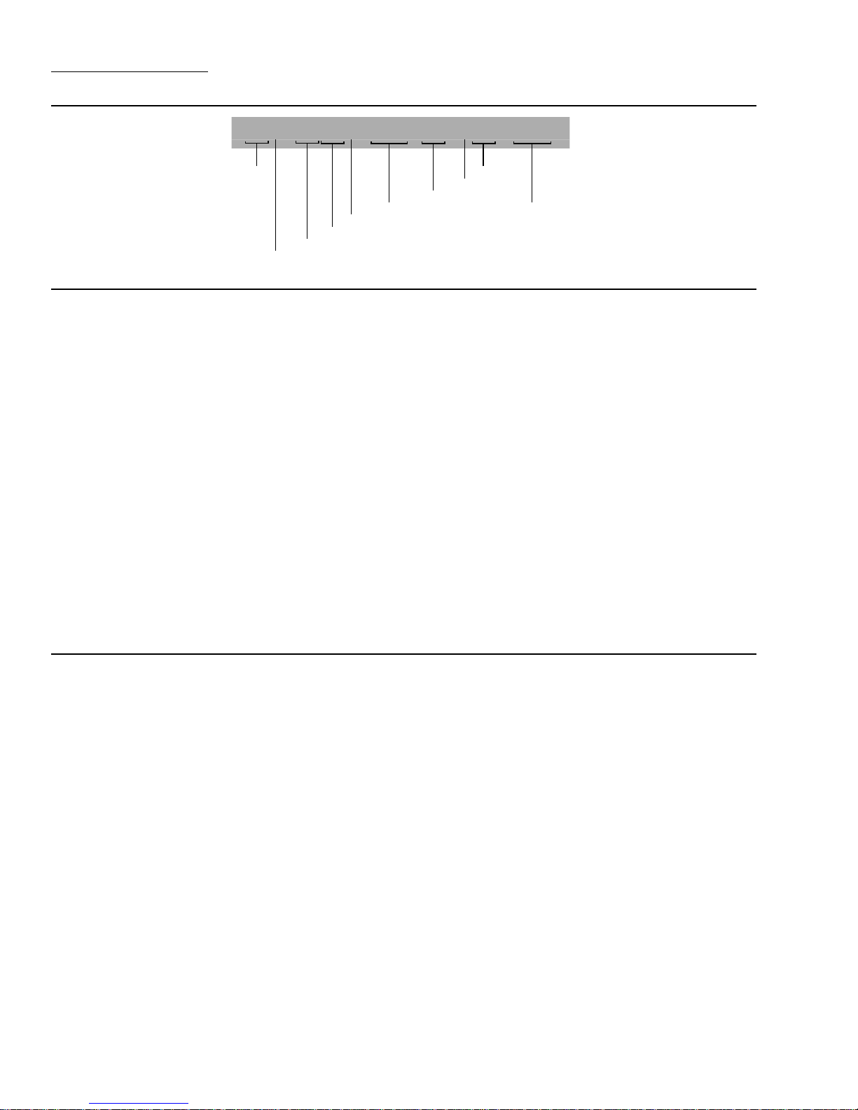
SECTION 2
WILDEN PUMP DESIGNATION SYSTEM
A2X / XXXXX / XXX / XX / X XX/ XXXX
MODEL
VALVE BALL S
DIAPHRAGMS
AIR VALVE
CENTER SECTION
WETTED PARTS & OUTER PISTON
AIR SYSTEM BASE TYPE
O-RINGS
VALVE SEAT
SPECIALTY
CODE
(if applicable)
MODEL A2 PLASTIC MATERIAL CODES
AIR SYSTEM BASE TYPE
B = ADAPTER BLOCK
P = PRO-FLO
®
T = TURBO-FLO™
WETTED PARTS & OUTER PISTON
KK = PVDF / PVDF
PP = POLYPROPYLENE /
POLYPROPYLENE
CENTER SECTION
PP = POLYPROPYLENE
AIR VALVE
A = ALUMINUM (available on A2T
only)
P = POLYPROPYLENE
U = UHMW PE (available
on A2B only)
DIAPHRAGMS
BNS = BUNA-N (Red Dot)
EPS = EPDM (Blue Dot)
FSS = SANIFLEX™
(Hytrel® (Cream))
NES = NEOPRENE (Green Dot)
PUS = POLYURETHANE (Clear)
TEU = PTFE W/EPDM
BACK-UP (White)
TNU = PTFE W/NEOPRENE
BACK-UP (White)
TSU = PTFE W/SANIFLEX™ BACK-UP
(White)
VTS = VITON® (White Dot)
WFS = WIL-FLEX™ (Santoprene®
(Orange Dot))
VALVE BALL
BN = BUNA-N (Red Dot)
EP = EPDM (Blue Dot)
FS = SANIFLEX™
(Hytrel® (Cream))
NE = NEOPRENE (Green Dot)
PU = POLYURETHANE (Brown)
TF = PTFE (White)
VT = VITON® (White Dot)
WF = WIL-FLEX™ (Santoprene®
(Orange Dot))
VALVE SEAT
K = PVDF
P = POLYPROPYLENE
VALVE SEAT O-RING
BN = BUNA-N
PU = POLYURETHANE (Brown)
TV = PTFE ENCAP. VITON
WF = WIL-FLEX™ (Santoprene®)
®
SPECIALTY CODES
0261 A2 Plastic, Accu-Flo™, 24V AC / 12V DC coil
0262 A2 Plastic, Accu-Flo™, 24V AC / 12V DC x-proof coil
0263 A2 Plastic, Accu-Flo™, 24V DC coil
0264 A2 Plastic, Accu-Flo™, 24V DC x-proof coil
0265 A2 Plastic, Accu-Flo™, 110V AC coil
0266 A2 Plastic, Accu-Flo™, 110V AC x-proof coil
0271 A2 Plastic, Accu-Flo™, 110V AC coil, Wil-Gard II™ 110V
0272 A2 Plastic, Accu-Flo™, 24V AC / 12V DC coil,
SS outer pistons
0273 A2 Plastic, Accu-Flo™, 24V DC coil, Wil-Gard II™ 110V
0362 Accu-Flo™, 110V AC coil, PFA coated hardware,
Wil-Gard II™ 110V
0451 A2 Plastic, Accu-Flo™, no coil, DIN flange
NOTE: MOST ELASTOMERIC MATERIALS USE COLORED DOTS FOR IDENTIFICATION.
THE THREE ACCU-FLO™ OPTIONS AVAILABLE:
1. AxT: This is the same Accu-Flo™ configuration that has been available from
Wilden since March 1994. An aluminum solenoid valve is attached directly to a
T-series center section and the shaft/inner piston configuration is altered.
2. AxP: This option uses a plastic (polypropylene or acetal) spacer that is
assembled between the Pro-Flo
same solenoid operator – coil assembly that is found on AxT pumps is assembled
on the plastic spacer discussed above for electronic interface. This spacer
combined with the Pro-Flo
AxT with a more chemically resistant option. Spacers will be available in the 1/4",
Viton is a registered trademark of DuPont Dow Elastomers.
WILDEN PUMP & ENGINEERING, LLC WIL-10070-E-03
®
air valve and the Pro-Flo® center section. The
®
air valve replaces the aluminum air valve used in the
0454 A2 Plastic, Accu-Flo™, 24V DC coil, DIN flange
0455 A2 Plastic, Accu-Flo™, 24V AC / 12V DC coil, DIN flange
0456 A2 Plastic, Accu-Flo™, 24V DC,
Intl. x-proof coil, DIN flange
0457 A2 Plastic, Accu-Flo™, 24V DC coil,
SS outer pistons, DIN flange
0458 A2 Plastic, Accu-Flo™, 24V DC coil,
Wil-Gard II™ 220V, DIN flange
0567 Split manifold, Accu-Flo™, 24V DC coil
0570 Split manifold, Accu-Flo™, 24V AC / 12V DC coil
0509 adapter block, no muffler, P2R center section
0518 adapter block, no muffler, T2R center section
1/2", and 1" sizes. The use of the Pro-Flo
applications (refer to EOM for details). The AxP provides the Pro-Flo
lower start-up pressure, reduced blow-by, and increased life.
3. AxB: This option uses an Adapter Block in place of an air valve. A user supplied,
4-way pneumatic valve must be used in conjunction with this technology. This
configuration enables the solenoid valve to be remotely installed, preventing
chemical attack in very aggressive environments. Adapter Blocks are available
for both the T and P-series center sections in all pump sizes. (See EOM AxB for
details.) Note: the “x” in the above Accu-Flo™ descriptions are used in place of a
pump model size. See Pump Designation System chart above.
2
®
ADS provides additional flow in most
®
benefits of
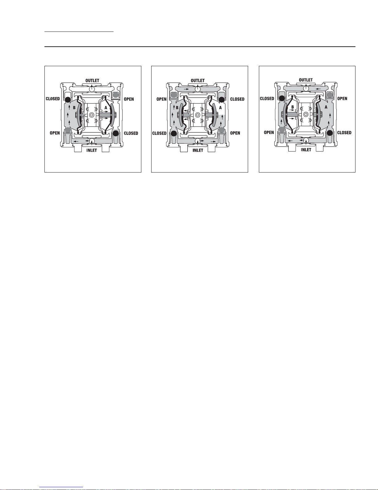
SECTION 3
THE WILDEN PUMP — HOW IT WORKS
The Wilden diaphragm pump is an air-operated, positive displacement, self-priming pump. These drawings show the flow
pattern through the pump upon its initial stroke. It is assumed the pump has no fluid in it prior to its initial stroke.
RIGHT STROKE LEFT STROKE RIGHT STROKE
FIGURE 1 When the solenoid is energized, the air valve directs pressure
to the back side of diaphragm A. The
compressed air is applied directly to the
liquid column separated by elastomeric
diaphragms. The diaphragm acts as
a membrane between the compressed
air and the liquid, balancing the load
and removing mechanical stress from
the diaphragm. The compressed
air moves the diaphragm away from
the center section of the pump. The
opposite diaphragm is pulled in by
the shaft connected to the pressurized diaphragm. Diaphragm B is on its
suction stroke; air behind the diaphragm
has been forced out to the atmosphere
through the exhaust port. The movement of diaphragm B toward the center
section of the pump creates a vacuum
within chamber B. Atmospheric pressure forces fluid into the inlet manifold
forcing the inlet valve ball off of its seat.
Liquid is free to move past the inlet
valve ball and fill the liquid chamber (see
shaded area).
FIGURE 2 When the solenoid valve is
deenergized, the air valve redirects pressurized air to the back side of diaphragm
B. The pressurized air forces diaphragm
B away from the center section while
pulling diaphragm A to the center
section. Diaphragm B is now on its
discharge stroke. Diaphragm B forces
the inlet valve ball onto its seat due
to the hydraulic forces developed in
the liquid chamber and manifold of the
pump. These same hydraulic forces lift
the discharge valve ball off of its seat,
while the opposite discharge valve ball
is forced onto its seat, forcing fluid to
flow through the pump discharge. The
movement of diaphragm A toward the
center section of the pump creates a
vacuum within liquid chamber A. Atmospheric pressure forces fluid into the
inlet manifold of the pump. The inlet
valve ball is forced off of its seat allowing
the fluid being pumped to fill the liquid
chamber.
FIGURE 3 Once the solenoid valve is
reenergized, the air is directed to the
back side of diaphragm A, which starts
diaphragm B on its exhaust stroke. As
the pump reaches its original starting
point, each diaphragm has gone through
one intake and one discharge stroke.
This constitutes one complete pumping cycle. The pump may take several
cycles to completely prime depending
on the conditions of the application.
3
WILDEN PUMP & ENGINEERING, LLCWIL-10070-E-03
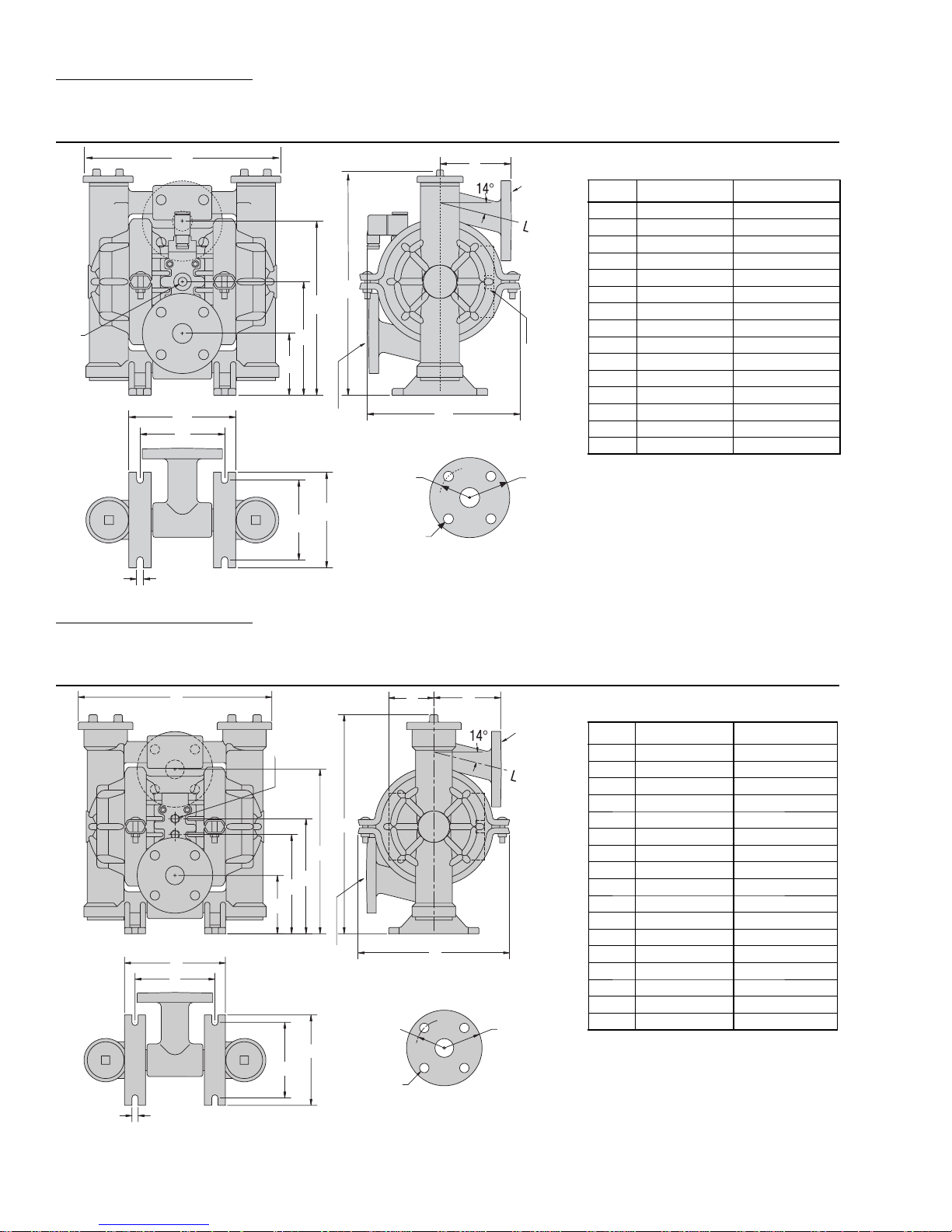
SECTION 4A
DIMENSIONAL DRAWING
A2T PLASTIC ACCU-FLO™
6 mm
(1/4”)
BSP
(FNPT) AIR
INLET
A
E
D
C
B
H
J
25 mm (1”)
ANSI/DIN FLANGE
LIQUID INLET
F
G
25 mm (1”)
ANSI/DIN
FLANGE
LIQUID
DISCHARGE
C
13 mm
(1/2”)
BSP
(FNPT) AIR
EXHAUST
DIMENSIONS
ITEM METRIC (mm) STANDARD (inch)
A 297 11.7
B 74 2.9
C 163 6.4
D 251 9.9
E 335 13.2
F 107 4.2
G 229 9.0
H 157 6.2
J 124 4.9
K 114 4.5
L 137 5.4
M 10 0.4
N 79 DIA. 3.1 DIA.
P 109 DIA. 4.3 DIA.
R 15 DIA. 0.6 DIA.
N
L
K
M
R
150 pound class
FLANGE
P
SECTION 4B
DIMENSIONAL DRAWING
A2B PLASTIC (T-SERIES CENTER SECTION)
A
K
L
P
6 mm (1/4”)
BSP (FNPT)
AIR INLET
E
D
C
B
25 mm (1”)
ANSI/DIN FLANGE
LIQUID INLET
N
M
F
R
T
150 pound class
J
FLANGE
HG
25 mm (1”)
ANSI/DIN
FLANGE
LIQUID
DISCHARGE
DIMENSIONS
ITEM METRIC (mm) STANDARD (inch)
C
S
A 297 11.7
B 74 2.9
C 150 5.9
D 173 6.8
E 251 9.9
F 335 13.2
G 69 2.7
H 107 4.2
J 239 9.4
K 114 4.5
L 137 5.4
M 124 4.9
N 157 6.2
P 10 0.4
R 79 DIA. 3.1 DIA.
S 109 DIA. 4.3 DIA.
T 15 DIA. 0.6 DIA.
WILDEN PUMP & ENGINEERING, LLC WIL-10070-E-03
4
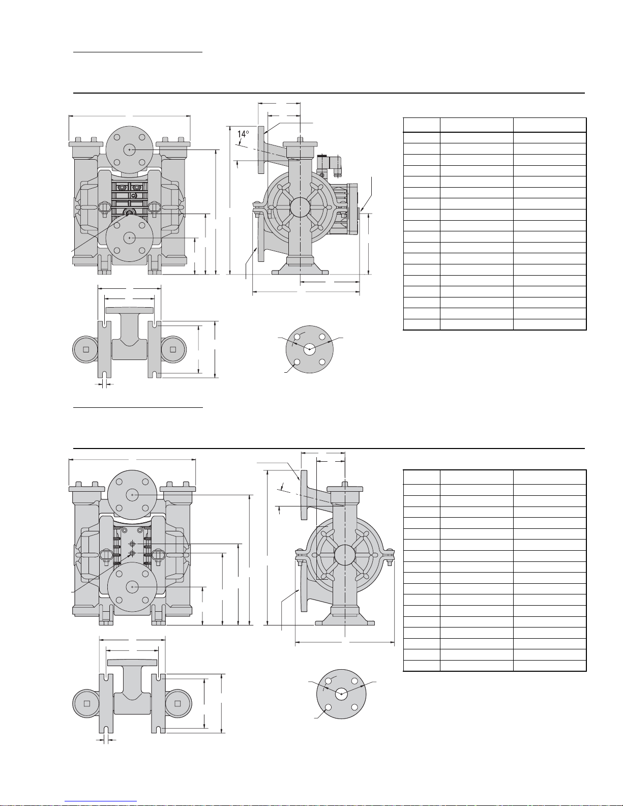
SECTION 4C
DIMENSIONAL DRAWING
A2P PLASTIC ACCU-FLO™
F
6 mm
(1/4”)
BSP
(FNPT)
AIR
INLET
R
SECTION 4D
A
E
D
C
B
L
M
25 mm (1”)
ANSI/DIN FLANGE
LIQUID INLET
P
N
G
S
U
25 mm (1”)
ANSI/DIN FLANGE LIQUID
DISCHARGE
K
FLANGE
150 pound class
J
13 MM (1/2”)
BSP (FNPT) AIR
EXHAUST
H
T
DIMENSIONS
ITEM METRIC (mm) STANDARD (inch)
A 297 11.7
B 74 2.9
C 147 5.8
D 307 12.1
E 356 14.0
F 107 4.2
G 69 2.7
h 91 3.6
J 142 5.6
K 259 10.2
L 114 4.5
M 137 5.4
N 124 4.9
P 157 6.2
R 10 0.4
S 79 DIA. 3.1 DIA.
T 109 DIA. 4.3 DIA.
U 15 DIA. 0.6 DIA.
DIMENSIONAL DRAWING
A2B PLASTIC (P-SERIES CENTER SECTION)
R
T
H
G
J
FLANGE
150 pound class
6 mm
(1/4”)
BSP
(FNPT)
AIR
INLET
FLANGE LIQUID
C
B
N
M
25 mm (1”)
ANSI/DIN
DISCHARGE
E
D
ANSI/DIN FLANGE
F
25 mm (1”)
LIQUID INLET
A
K
L
P
DIMENSIONS
ITEM METRIC (mm) STANDARD (inch)
A 297 11.7
B 74 2.9
C 168 6.6
D 188 7.4
E 307 12.1
F 356 14.0
G 66 2.6
H 107 4.2
J 239 9.4
K 114 4.5
L 137 5.4
M 124 4.9
N 157 6.2
P 10 0.4
R 79 DIA. 3.1 DIA.
S 109 DIA. 4.3 DIA.
T 15 DIA. 0.6 DIA.
S
5
WILDEN PUMP & ENGINEERING, LLCWIL-10070-E-03
 Loading...