

Wilden A200P Advanced Plastic Series Manual
A200P
Advanced™ Series PLASTIC Pumps
EOM
Engineering
Operation &
Maintenance
Simplify your process
WIL-11060-E-03
REPLACES WIL-11060-E-02
TABLE OF CONTENTS
SECTION 1 CAUTIONS—READ FIRST! . . . . . . . . . . . . . . . . . . . . . . . . . . . . . . . . . . . . . . . . . . . . . .1
SECTION 2 WILDEN PUMP DESIGNATION SYSTEM . . . . . . . . . . . . . . . . . . . . . . . . . . . . . . . . . 2
SECTION 3 HOW IT WORKS—PUMP & AIR DISTRIBUTION SYSTEM . . . . . . . . . . . . . . . . 3
SECTION 4 DIMENSIONAL DRAWINGS . . . . . . . . . . . . . . . . . . . . . . . . . . . . . . . . . . . . . . . . . . . . .4
SECTION 5 PERFORMANCE
A. A200P Performance Curves
Rubber-Fitted . . . . . . . . . . . . . . . . . . . . . . . . . . . . . . . . . . . . . . . . . . . . . . . . . . . . . . . .5
PTFE-Fitted . . . . . . . . . . . . . . . . . . . . . . . . . . . . . . . . . . . . . . . . . . . . . . . . . . . . . . . . . . 5
B. Suction Lift Curves . . . . . . . . . . . . . . . . . . . . . . . . . . . . . . . . . . . . . . . . . . . . . . . . . . . . .6
SECTION 6 SUGGESTED INSTALLATION, OPERATION & TROUBLESHOOTING . . . . . . . . 7
SECTION 7 EXPLODED VIEW AND PARTS LISTING
A200P Advanced™ Plastic
Rubber-Fitted . . . . . . . . . . . . . . . . . . . . . . . . . . . . . . . . . . . . . . . . . . . . . . . . . . . . . . . 12
PTFE-Fitted . . . . . . . . . . . . . . . . . . . . . . . . . . . . . . . . . . . . . . . . . . . . . . . . . . . . . . . . . 14
SECTION 8 ELASTOMER OPTIONS . . . . . . . . . . . . . . . . . . . . . . . . . . . . . . . . . . . . . . . . . . . . . . . . .16
Section 1
CAUTIONS—READ FIRST!
TEMPERATURE LIMITS*
Wetted Path
Polypropylene (PP) 0°C to 79.4°C 32°F to 175°F
Polyvinylidene fl uoride (PVDF)
-12.2°C to 107.2°C 10°F to 225°F
PTFE PFA -28.9°C to 87.8°C -20°F to 190°F
Elastomers
Neoprene -17.8°C to 93.3°C 0°F to 200°F
Buna-N -12.2°C to 82.2°C 10°F to 180°F
EPDM -51.1°C to 137.8°C -60°F to 280°F
Viton
Wil-Flex™ -40°C to 107.2°C -40°F to 225°F
Polyurethane 12.2°C to 65.6°C 10°F to 150°F
Tetra-Flex™ PTFE w/Neoprene
4.4°C to 107.2°C 40°F to 225°F
Tetra-Flex™ PTFE w/EPDM
-10°C to 137°C 14°F to 280°F
Polytetrafl uoroethylene (PTFE)
4.4°C to 104.4°C 40°F to 220°F
*Elastomer choice may change temperature limits
®
-40°C to 176.7°C -40°F to 350°F
CAUTION: When choosing pump materials, be
sure to check the temperature limits for all wetted
components. Example: Viton® has a maximum
limit of 176.7°C (350°F) but polypropylene has a
maximum limit of only 79.4°C (175°F).
CAUTION: Maximum temperature limits are based
upon mechanical stress only. Certain chemicals
will signifi cantly reduce maximum safe operating
temperatures. Consult engineering guide for
chemical compatibility and temperature limits.
CAUTION: Always wear safety glasses when
operating pump. If diaphragm rupture occurs,
material being pumped may be forced out air
exhaust.
WARNING: Prevention of static sparking — If
static sparking occurs, fi re or explosion could
result. Proper grounding of pump, valves, and
containers is critical when handling fl ammable
fl uids or whenever discharge of static electricity is
a hazard.
CAUTION: Advanced™ series plastic pumps
are made with plastic that is not UV stabilized.
Direct sunlight for prolonged periods can cause
deterioration of plastics.
CAUTION: Before any maintenance or repair is
attempted, the compressed air line to the pump
should be disconnected and all air pressure
allowed to bleed from pump. Disconnect all
intake, discharge and air lines. Drain the pump by
turning it upside down and allowing any fl uid to
fl ow into a suitable container.
CAUTION: Blow out air line for 10 to 20 seconds
before attaching to pump to make sure all pipe
line debris is clear. Use an in-line air fi lter. A 5µ
(micron) air fi lter is recommended.
NOTE: Tighten all bolts prior to installation.
Fittings may loosen during transportation.
NOTE: When installing polytetrafl uoroethylene
(PTFE) diaphragms, it is important to tighten
outer pistons simultaneously (turning in opposite
directions) to ensure tight fi t.
CAUTION: Verify the chemical compatibility of
the process and cleaning fl uid to the pump’s
component materials in the Chemical Resistance
Guide (see E4).
CAUTION: When removing the end cap using
compressed air, the air valve end cap may come
out with considerable force. Hand protection
such as a padded glove or rag should be used to
capture the end cap.
CAUTION: Do not over-tighten the air inlet reducer
bushing. Additionally, too much torque on the
muffl er may damage the air valve muffl er plate.
Do not exceed 0.9 N·m (8 in-lbs).
CAUTION: Only explosion proof (NEMA 7)
solenoid valves should be used in areas where
explosion proof equipment is required.
NOTE: Do not exceed 5.2 bar (75 psig) air supply
for PFA pumps.
CAUTION: Do not exceed 8.6 bar (125 psig) air
supply on polypropylene and PVDF pumps.
WIL-11060-E-03 1 WILDEN PUMP & ENGINEERING, LLC
CAUTION: Do not lubricate lube-free pumps.
CAUTION: The A200P pump is not submersible.
NOTE: When reinstalling the outer pistons, apply
two (2) drops of Loctite® 246 to the shaft internal
threads before the diaphragm assembly.

Section 2
WILDEN PUMP DESIGNATION SYSTEM
A200 ADVANCED™
PLASTIC
25 mm (1") Pump
Maximum Flow Rate:
170 LPM (45 GPM)
Maximum Operating
Pressure for PFA
is 5.2 bar (75 psig)
MATERIAL CODES
WETTED PARTS & OUTER PISTON
KK = PVDF / PVDF
PK = POLYPROPYLENE / PVDF
TT = PTFE / PTFE
CENTER SECTION
PP = POLYPROPYLENE
AIR VALVE
P = POLYPROPYLENE
LEGEND
A200P / XXXXX / XXX / XX / XXX / XXXX
MODEL
VALVE BALLS
DIAPHRAGMS
AIR VALVE
CENTER SECTION
WETTED PARTS & OUTER PISTON
DIAPHRAGMS
BNS = BUNA-N (Red Dot)
EPS = EPDM (Blue Dot)
FSS = SANIFLEX™
[Hytrel® (Cream)]
NES = NEOPRENE (Green Dot)
PUS = POLYURETHANE (Clear)
TEU = PTFE W/EPDM
BACK-UP (White)
TNU = PTFE W/NEOPRENE
BACK-UP (White)
TSU = PTFE W/SANIFLEX™
BACK-UP (White)
VTS = VITON® (White Dot)
WFS = WIL-FLEX™ [Santoprene®
(Orange Dot)]
O-RINGS
VALVE SEAT
VALVE BALL
BN = BUNA-N (Red Dot)
EP = EPDM (Blue Dot)
FS = SANIFLEX™
[Hytrel® (Cream)]
NE = NEOPRENE (Green Dot)
PU = POLYURETHANE (Brown)
TF = PTFE (White)
VT = VITON® (White Dot)
WF = WIL-FLEX™ [Santoprene®
(Orange Dot)]
VALVE SEAT
K = PVDF
P = POLYPROPYLENE
T = PTFE PFA
SPECIALTY
CODE
(if applicable)
SPECIALTY CODES
0150 Accu-Flo™, 24V DC coil
0151 Accu-Flo™, 24V AC / 12V DC coil
0167 Accu-Flo™, 24V AC / 12V DC coil,
Wil-Gard II™ 110V
0180 Accu-Flo™, 24V AC / 12V DC coil, PFA coated
0360 Accu-Flo™, 24V DC coil, DIN flange
NOTE: MOST ELASTOMERIC M ATERIALS USE COLORED DO TS FOR IDENTIFICATION.
®
Viton
is a registered trademark of DuPont Dow Elastomers.
VALVE SEAT O-RING
BN = BUNA-N
PU = POLYURETHANE (Brown)
TV = PTFE ENCAP. VITON
WF = WIL-FLEX™ (Santoprene®)
®
WILDEN PUMP & ENGINEERING, LLC 2 WIL-11060-E-03

Section 3
HOW IT WORKS—PUMP
The Wilden diaphragm pump is an air-operated, positive displacement, self-priming pump. These drawings show fl ow pattern
through the pump upon its initial stroke. It is assumed the pump has no fl uid in it prior to its initial stroke.
FIGURE 1 The air valve directs pressurized
air to the back side of diaphragm A. The
compressed air is applied directly to the
liquid column separated by elastomeric
diaphragms. The diaphragm acts as
a separation membrane between the
compressed air and liquid, balancing the
load and removing mechanical stress from
the diaphragm. The compressed air moves
the diaphragm away from the center block
of the pump. The opposite diaphragm is
pulled in by the shaft connected to the
pressurized diaphragm. Diaphragm B is on
its suction stroke; air behind the diaphragm
has been forced out to the atmosphere
through the exhaust port of the pump.
The movement of diaphragm B toward the
center block of the pump creates a vacuum
within chamber B. Atmospheric pressure
forces fl uid into the inlet manifold forcing
the inlet valve ball off its seat. Liquid is free
to move past the inlet valve ball and fi ll the
liquid chamber (see shaded area).
HOW IT WORKS—AIR DISTRIBUTION SYSTEM
FIGURE 2 When the pressurized diaphragm,
diaphragm A, reaches the limit of its
discharge stroke, the air valve redirects
pressurized air to the back side of diaphragm
B. The pressurized air forces diaphragm B
away from the center block while pulling
diaphragm A to the center block. Diaphragm
B is now on its discharge stroke. Diaphragm
B forces the inlet valve ball onto its seat due
to the hydraulic forces developed in the liquid
chamber and manifold of the pump. These
same hydraulic forces lift the discharge valve
ball off its seat, while the opposite discharge
valve ball is forced onto its seat, forcing
fl uid to fl ow through the pump discharge.
The movement of diaphragm A toward the
center block of the pump creates a vacuum
within liquid chamber A. Atmospheric
pressure forces fl uid into the inlet manifold
of the pump. The inlet valve ball is forced off
its seat allowing the fl uid being pumped to
fi ll the liquid chamber.
The Pro-Flo
moving parts: the air valve spool, the pilot spool, and the main
shaft/diaphragm assembly. The heart of the system is the air
valve spool and air valve. As shown in Figure A, this valve design
incorporates an unbalanced spool. The smaller end of the spool
is pressurized continuously, while the large end is alternately
pressurized then exhausted to move the spool. The spool directs
pressurized air to one air chamber while exhausting the other. The
air causes the main shaft/diaphragm assembly to shift to one side
— discharging liquid on that side and pulling liquid in on the other
side. When the shaft reaches the end of its stroke, the inner piston
actuates the pilot spool, which pressurizes and exhausts the large
end of the air valve spool. The repositioning of the air valve spool
routes the air to the other air chamber.
®
patented air distribution system incorporates three
FIGURE 3 At completion of the stroke,
the air valve again redirects air to the
back side of diaphragm A, which starts
diaphragm B on its exhaust stroke. As
the pump reaches its original starting
point, each diaphragm has gone through
one exhaust and one discharge stroke.
This constitutes one complete pumping
cycle. The pump may take several cycles
to completely prime depending on the
conditions of the application.
WIL-11060-E-03 3 WILDEN PUMP & ENGINEERING, LLC
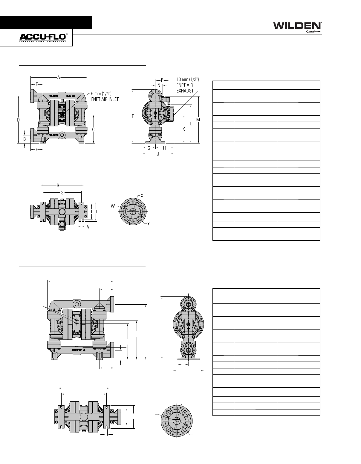
Section 4
DIMENSIONAL DRAWINGS
A200P Advanced™ Plastic
DIMENSIONS
ITEM METRIC (mm) STANDARD (inch)
A457 18.0
B66 2.6
C259 10.2
D381 15.0
E99 3.9
F434 17.1
G104 4.1
H150 5.9
J257 10.1
K226 8.9
L310 12.2
M378 14.9
N58 2.3
P 109 4.3
R353 13.9
S310 12.2
T124 4.9
U157 6.2
V10 0.4
DIN (mm) ANSI (inch)
W 85 DIA. 3.1 DIA.
X 115 DIA. 4.3 DIA.
Y 14 DIA . 0.6 DIA.
A200B Advanced™ Plastic
A
D
13 mm (1/2")
FNPT AIR
INLET
F
E
B
D
K
L
N
M
P
DIMENSIONS
ITEM METRIC (mm) STANDARD (inch)
A457 18.0
B66 2.6
C381 15.0
D99 3.9
G
C
H
J
S
R
T
E249 9.8
F269 10.6
G434 17.1
H71 2.8
J213 8.4
K353 13.9
L310 12.2
M124 4.9
N157 6.2
P10 0.4
DIN (mm) ANSI (inch)
W 85 DIA. 3.1 DIA.
X 115 DIA. 4.3 DIA.
Y 14 DIA . 0.6 DIA.
WILDEN PUMP & ENGINEERING, LLC 4 WIL-11060-E-03
 Loading...