

Wilden A2 User Manual
EOM
Engineering
Operation &
Maintenance
A2
Original
Metal Pump
™
Where Innovation Flows
www.wildenpump.com
REPLACES WIL-10060- E-02
WI L-100 60 -E - 0 3
TABLE OF CONTENTS
SECTION 1 CAUTIONS—READ FIRST! ..............................................1
SECTION 2 WILDEN PUMP DESIGNATION SYSTEM .................................2
SECTION 3 HOW IT WORKS—PUMP & AIR DISTRIBUTION SYSTEM ................3
SECTION 4 DIMENSIONAL DRAWINGS .............................................4
SECTION 5 PERFORMANCE
A2T Metal Rubber-Fitted (T-series Center Section) ..............................9
A2T Metal PTFE-Fitted (T-series Center Section) ................................9
A2P Metal Rubber-Fitted (P-series Center Section) .............................10
A2P Metal PTFE-Fitted (P-series Center Section) ...............................10
SECTION 6 70/30 OPERATING CONDITION
A2T Metal Rubber-Fitted (T-series Center Section) .............................11
A2T Metal PTFE-Fitted (T-series Center Section) ...............................11
A2P Metal Rubber-Fitted (P-series Center Section) .............................11
A2P Metal PTFE-Fitted (P-series Center Section) ...............................11
SECTION 7 SUGGESTED INSTALLATION ...........................................12
Operating Principles ......................................................13
Operation & Maintenance .................................................13
Troubleshooting .........................................................14
SECTION 8 DISASSEMBLY / ASSEMBLY ...........................................15
Reassembly Hints & Tips ..................................................17
SECTION 9 EXPLODED VIEW & PARTS LISTING
A2T Metal
T-series Center Section ...............................................18
A2P Metal
P-series Center Section ...............................................20
SECTION
10
ELASTOMER OPTIONS .................................................22
Electrical Information .....................................................22
Section 1
CAUTIONS—READ FIRST!
TEMPERATURE LIMITS:
Polypropylene 0°C to 79°C 32°F to 175°F
PVDF –12°C to 107°C 10°F to 225°F
PFA 7°C to 107°C 20°F to 225°F
Neoprene –18°C to 93°C 0°F to 200°F
Buna-N –12°C to 82°C 10°F to 180°F
EPDM –51°C to 138°C –60°F to 280°F
Viton
®
FKM –40°C to 177°C –40°F to 350°F
Wil-Flex™ –40°C to 107°C –40°F to 225°F
Saniflex™ –29°C to 104°C –20°F to 220°F
Polyurethane –12°C to 66°C 10°F to 150°F
Polytetrafluoroethylene (PTFE)1 4°C to 104°C 40°F to 220°F
Nylon –18°C to 93°C 0°F to 200°F
Acetal –29°C to 82°C –20°F to 180°F
SIPD PTFE
SIPD PTFE
with
Neoprene-backed
with
EPDM-backed –10°C to 137°C 14°F to 280°F
4°C to 104°C 40°F to 220°F
Polyethylene 0°C to 70°C 32°F to 158°F
Geolast
CAUTION: When choosing pump materials, be
CAUTION:
CAUTION: Always wear safety glasses when
®
–40°C to 82°C –40°F to 180°F
1
4°C to 149°C (40°F to 300°F) - 13 mm (1/2") and 25 mm (1") models only.
sure to check the temperature limits for all wetted
components.
Maximum temperature limits are based
upon mechanical stress only. Certain chemicals
will significantly reduce maximum safe operating
temperatures. Consult the Chemical Resistance Guide
for chemical compatibility and temperature limits.
operating pump. If diaphragm rupture occurs,
material being pumped may be forced out air
exhaust.
CAUTION: Before any maintenance or repair is
attempted, the compressed air line to the pump
should be disconnected and all air pressure
allowed to bleed from pump. Disconnect all intake,
discharge and air lines. Drain the pump by turning
it upside down and allowing any fluid to flow into
a suitable container. ghly flushed before installing
into process lines. FDA- and USDA-approved
pumps should be cleaned and /or sanitized before
being used.
CAUTION: Blow out air line for 10 to 20 seconds
before attaching to pump to make sure all pipe line
debris is clear. Use an in-line air filter. A 5µ (micron)
air filter is recommended.
NOTE: Tighten all fasteners prior to installation.
Fittings may loosen during transportation.
NOTE: When installing PTFE diaphragms, it is
important to tighten outer pistons simultaneously
(turning in opposite directions) to ensure tight fit.
NOTE: Before starting disassembly, mark a line
from each liquid chamber to its corresponding air
chamber. This line will assist in proper alignment
during reassembly.
CAUTION: Verify the chemical compatibility of the
process and cleaning fluid to the pump’s component
materials in the Chemical Resistance Guide.
CAUTION: Only explosion proof (NEMA 7) solenoid
valves should be used in areas where explosion proof
equipment is required.
WARNING: Prevent static sparking — If static
sparking occurs, fire or explosion could result.
Pump, valves, and containers must be properly
grounded when handling flammable fluids and
whenever discharge of static electricity is a hazard.
CAUTION: Do not exceed 8.6 bar (125 psig) air
supply pressure.
WIL-10060-E-03
CAUTION: Do not lubricate lube-free pumps.
CAUTION: The A2 pump is not submersible.
3
WILDEN PUMP & ENGINEERING, LLC
Section 2
WILDEN PUMP DESIGNATION SYSTEM
A2 METAL
38 mm (1-1/2") Pump
Maximum Flow Rate:
507 lpm (134 gpm)
MATERIAL CODES
AIR SYSTEM BASE TYPE
B = ADAPTER BLOCK
P = PRO-FLO
T = TURBO-FLO™
WETTED PARTS & OUTER PISTON
AA = ALUMINUM / ALUMINUM
HH = ALLOY C / ALLOY C
SS = STAINLESS STEEL / STAINLESS STEEL
CENTER SECTION
AA = ALUMINUM
CC = PTFE-COATED ALUMINUM
NN = NICKEL-PLATED ALUMINUM
PP = POLYPROPYLENE
AIR VALVE
A = ALUMINUM (available on A2T only)
L = ACETAL (available on A2P AND A2B only)
P = POLYPROPYLENE (available on
U = UHMW PE (available on A2B only)
®
A2P AND A2B only)
LEGEND
DIAPHRAGMS
BNS = BUNA-N (Red Dot)
EPS = EPDM (Blue Dot)
FSS = SANIFLEX™ [Hytrel® (Cream)]
NES = NEOPRENE (Green Dot)
PUS = POLYURETHANE (Clear)
TEU = PTFE W/EPDM BACK-UP (White)
TNU = PTFE W/NEOPRENE BACK-UP (White)
TSU = PTFE W/SANIFLEX™ BACK-UP (White)
VTS = VITON® (White Dot)
WFS = WIL-FLEX™ [Santoprene® (Orange Dot)]
VALVE BALL
BN = BUNA-N (Red Dot)
EP = EPDM (Blue Dot)
FS = SANIFLEX™ [Hytrel® (Cream)]
FV = SANITARY VITON® (Two White Dots)
NE = NEOPRENE (Green Dot)
PU = POLYURETHANE (Brown)
TF = PTFE (White)
VT = VITON® (White Dot)
WF = WIL-FLEX™ [Santoprene® (Orange Dot)]
A2 X / X XXX X / XXX / XX / X XX / XXXX
MODEL
AIR VALVE
CENTER SECTION
WETTED PARTS & OUTER PISTON
AIR SYSTEM BASE TYPE
O-RINGS
VALVE SEAT
VALVE BALLS
DIAPHRAGMS
VALVE SEAT
A = ALUMINUM
H = ALLOY C
S = STAINLESS STEEL
VALVE SEAT O-RING
BN = BUNA-N
EP = EPDM (Blue Dot)
FS = SANIFLEX™ [Hytrel® (Cream)]
PU = POLYURETHANE (Brown)
TF = PTFE (White)
WF = WIL-FLEX™ [Santoprene®]
SPECIALT Y
CODE
(if applicable)
SPECIALTY CODES
0100 Wil-Gard II™ 110 V
0102 Wil-Gard II™ Sensor Cables Only
0103 Wil-Gard II™ 2 20V
0206 PFA-coa ted hardware, Wil-Gard II ™ sensor wires onl y
0502 PFA-coated hardware
0520 Ultrapure II, w /Female Connections
0521 Ultrapure II, PFA-coated hardware, w /Female Connections
0522 Ultrapure II, w/Male Bondable Connections
0523 Ultrapure II, PFA-coated hardware, w /Male Bondable Connections
0524 Ultrapure II, w / Wil-Gard II™ 110V, Male Bondable Connections
0525 Ultrapure II, Female Connections, PFA-coated hardware,
Wil-Gard II™ sensor w ires ONLY
05 30 Ultrapure II, w / Wil-Gard II™ 110V, Female Connect ions
05 31 Ultrapure II, Female Connections, Wil-Gard II ™ sensor wires onl y
05 32 Ultrapure II, PFA-coated hardware, w /Wil -Gard II™ 110V,
Male Bondable Connections
NOTE: MOST ELASTOMERIC MATERIALS USE COLORED DOTS FOR IDENTIFICATION.
THE THREE ACCU-FLO™ OPTIONS AVAILABLE:
1. AxT: This is the same Accu-Flo™ configuration that has been available from Wilden
since March 1994. An aluminum solenoid valve is attached directly to a T-series center
section and the shaft/inner piston configuration is altered.
2. AxP: This option uses a plastic (polypropylene or acetal) spacer that is assembled
between the Pro-Flo® air valve and the Pro-Flo® center section. The same solenoid
operator – coil assembly that is found on AxT pumps is assembled on the plastic spacer
discussed above for electronic interface. This spacer together with the Pro-Flo® air valve
replaces the aluminum air valve used in the AxT with a more chemically resistant option.
Viton is a registered trademark of DuPont Dow Elastomers.
WILDEN PUMP & ENGINEERING, LLC
05 33 Ultrapure II, PFA-coated hardware,
w/ Wil-Gard II™ 220V, Male Bondable Connections
0560 Split Manifold
05 61 Split Manifold, PFA C oated hardware
056 3 Split Manifold, discharge only
056 4 Split Manifold, Inlet Only
06 03 PFA-coated hardware, Wil-Gard II™ 110V
06 08 PFA-coated hardware, Wil-Gard II™ 22 0V
0612 Ultrapure, PFA-coated hardware, Male Connection
0618 Ultrapure, PFA-coated hardware, w / Wil-Gard II™ 110V,
Male Connections
062 2 Ultrapure, w/Male Connections
06 23 Ultrapure, Adap ter Block, No Muf fler, Male Connections
06 24 Ultrapure, w/Wil-Gard II™ 110 V, Male Connections
06 60 Split Manifold, Wil -Gard II™ 110V
06 61 Split manifold, PFA-coated hardware, Wil-Gard II™ 110V
Spacers will be available in the 1/4”, 1/2”, and 1” sizes. The use of the Pro-Flo® ADS
provides additional flow in most applications (refer to EOM for details). The AxP provides
the Pro-Flo® benefits of lower start-up pressure, reduced blow-by, and increased life.
3. AxB: This option uses an Adapter Block in place of an air valve. A user supplied, 4-way
pneumatic valve must be used in conjunction with this technology. This configuration
enables the solenoid valve to be remotely installed, preventing chemical attack in very
aggressive environments. Adapter Blocks are available for both the T and P-series center
sections in all pump sizes. (See EOM AxB for details.)
Note: The “x” in the above Accu-Flo™ descriptions are used in place of a pump model
size. See Pump Designation System chart above.
4
WIL-10060-E-03

Section 3
HOW IT WORKS—PUMP
The Wilden diaphragm pump is an air-operated, positive displacement, self-priming pump. These drawings show the flow pattern
through the pump upon its initial stroke. It is assumed the pump has no fluid in it prior to its initial stroke.
RIGHT STROKE LEFT STROKE RIGHT STROKE
FIGURE 1 When the solenoid is
energized, the air valve directs pressure
to the back side of diaphragm A. The
compressed air is applied directly to the
liquid column separated by elastomeric
diaphragms. The diaphragm acts as a
membrane bet ween the compressed air
and the liquid, balancing the load and
mechanical stress from the diaphragm.
The compressed air moves the diaphragm
away from the center section of the pump.
The opposite diaphragm is pulled in by
the shaft connected to the pressurized
diaphragm. Diaphragm B is on its
suction stroke; air behind the diaphragm
has been forced out to the atmosphere
through the exhaust por t. The movement
of diaphragm B toward the center section
of the pump creates a vacuum within
chamber B. Atmospheric pressure forces
fluid into the inlet manifold forcing the
inlet valve ball of f of its seat. Liquid is
free to move past the inlet valve ball and
fill the liquid chamber (see shaded area).
FIGURE 2 When the solenoid valve is
deenergized, the air valve redirects
pressurized air to the back side of
diaphragm B. The pressurized air forces
diaphragm B away from the center
section while pulling diaphragm A to the
center section. Diaphragm B is now on
its discharge stroke. Diaphragm B forces
the inlet valve ball onto its seat due to the
hydraulic forces developed in the liquid
chamber and manifold of the pump. These
same hydraulic forces lift the discharge
valve ball off of its seat, while the opposite
discharge valve ball is forced onto its seat,
forcing fluid to flow through the pump
discharge. The movement of diaphragm
A toward the center section of the pump
creates a vacuum within liquid chamber
A. Atmospheric pressure forces fluid into
the inlet manifold of the pump. The inlet
valve ball is forced off of its seat allowing
the fluid being pumped to fill the liquid
chamber.
FIGURE 3 Once the solenoid valve is
reenergized the air is directed to the
back side of diaphragm A, which starts
diaphragm B on its exhaust stroke. As
the pump reaches its original starting
point, each diaphragm has gone through
one intake and one discharge stroke.
This constitutes one complete pumping
cycle. The pump may take several cycles
to completely prime depending on the
conditions of the application.
WIL-10060-E-03
5
WILDEN PUMP & ENGINEERING, LLC
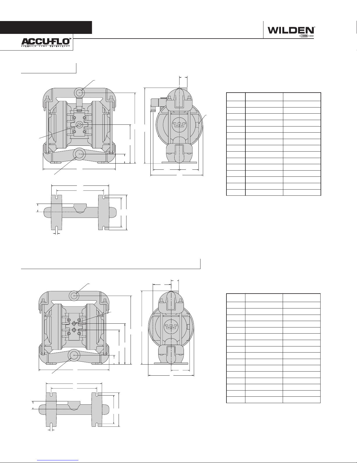
Section 4
A2T Metal
6 mm (1/4”)
BSP (FNPT)
AIR INLET
25 mm (1”) BSP (FNPT)
LIQUID INLET
DIMENSIONAL DRAWINGS
A
K
L
19 mm (3/4”) BSP (FNPT)
LIQUID DISCHARGE
B
D
E
C
F
G H
J
13 mm
(1/2”) BSP
(FNPT)
AIR
EXHAUST
DIMENSIONS
ITEM METRIC (mm) STANDARD (inch)
A 267 10.5
B 36 1.4
C 137 5.4
D 254 10.0
E 279 11.0
F 28 1.1
G 97 3.8
H 76 3.0
J 191 7.5
K 211 8.3
L 173 6.8
M 107 4.2
N 127 5.0
P 8 0.3
R 33 1.3
M N
P
A2B Metal (T-Series Center Section)
H
G
K
25 mm (1”) BSP (FNPT)
LIQUID INLET
R
19 mm (3/4”) BSP (FNPT)
LIQUID DISCHARGE
A
L
M
6 mm
(1/4”) BSP
(FNPT)
AIR INLET
D
C
B
NSP
FF
E
DIMENSIONS
ITEM METRIC (mm) STANDARD (inch)
A 267 10.5
B 36 1.4
C 130 5.1
D 152 6.0
E 254 10.0
F 279 11.0
G 69 2.7
H 28 1.1
J 76 3.0
K 173 6.8
J
L 211 8.3
M 173 6.8
N 107 4.2
P 127 5.0
R 33 1.3
S 8 0.3
WILDEN PUMP & ENGINEERING, LLC
6
WIL-10060-E-03
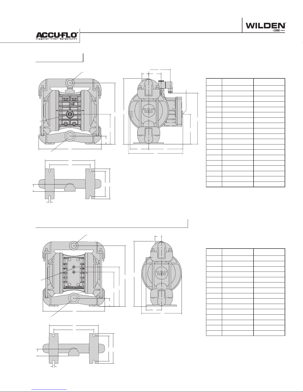
A2P Metal
DIMENSIONAL DRAWINGS
6 mm
(1/4”) BSP
(FNPT)
AIR INLET
25 mm (1”) BSP (FNPT)
LIQUID INLET
U
V
19 mm (3/4”) BSP (FNPT)
LIQUID DISCHARGE
A
P
R
B
S T
H
G
F
13 mm
(1/2”) BSP
(FNPT) AIR
EXHAUST
DIMENSIONS
ITEM METRIC (mm) STANDARD (inch)
A 267 10.5
B 36 1.4
C 124 4.9
D 254 10.0
E
D
K
E 279 11.0
F 28 1.1
G 53 2.1
H 91 3.6
C
J
J 124 4.9
K 213 8.4
L 76 3.0
L M
N
M 142 5.6
N 229 9.0
P 211 8.3
R 173 6.8
S 107 4.2
T 127 5.0
U 33 1.3
V 8 0.3
A2B Metal (P-Series Center Section)
19 mm (3/4”) BSP (FNPT)
LIQUID DISCHARGE
F
6 mm
(1/4”) BSP
(FNPT)
AIR INLET
25 mm (1”) BSP
(FNPT) LIQUID INLET
P
B
A
K
L
M N
E
D
C
H
G
DIMENSIONS
ITEM METRIC (mm) STANDARD (inch)
A 267 10.5
B 36 1.4
C 145 5.7
D 168 6.6
E 254 10.0
F 279 11.0
G 28 1.1
H 66 2.6
J 173 6.8
K 211 8.3
J
L 173 6.8
M 107 4.2
N 127 5.0
P 33 1.3
R 8 0.3
R
WIL-10060-E-03
7
WILDEN PUMP & ENGINEERING, LLC
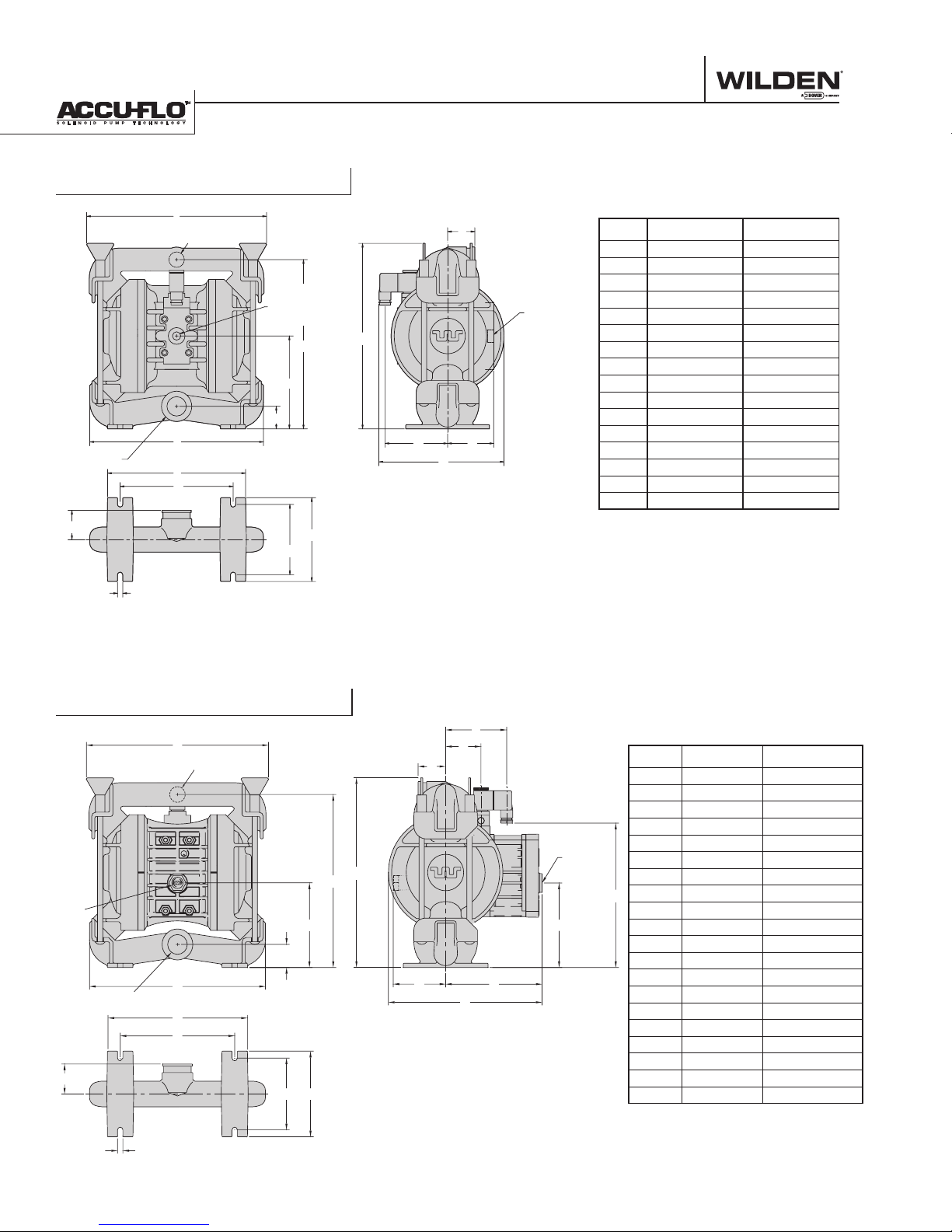
DIMENSIONAL DRAWINGS
A2T Metal Saniflo FDA
E
38 mm (1-1/2”)
TRI-CLAMP
6 mm
(1/4”) BSP
(FNPT)
AIR INLET
D
C
B
38 mm (1-1/2”)
TRI-CLAMP
S
A
L
M
P
N
DIMENSIONS
G
13 mm
(1/2”) BSP
(FNPT)
AIR
EXHAUST
F
H J
K
ITEM METRIC (mm) STANDARD (inch)
A 267 10.5
B 36 1.4
C 137 5.4
D 254 10.0
E 267 10.5
F 295 11.6
G 41 1.6
H 97 3.8
J 76 3.0
K 191 7.5
L 211 8.3
M 173 6.8
N 107 4.2
P 127 5.0
R 8 0.3
S 43 1.7
R
A2P Metal Saniflo FDA
E
38 mm (1-1/2”)
TRI-CLAMP
6 mm
(1/4”)
BSP
(FNPT)
AIR
INLET
W
38 mm (1-1/2”)
TRI-CLAMP
A
R
S
C
B
T U
J
H
G
DIMENSIONS
ITEM METRIC (mm) STANDARD (inch)
A 267 10.5
B 36 1.4
C 124 4.9
13 mm
(1/2”) BSP
(FNPT)
F
D
AIR
EXHAUST
D 254 10.0
E 267 10.5
F 295 11.6
G 41 1.6
H 53 2.1
L
J 91 3.6
K
K 124 4.9
L 213 8.4
M 76 3.0
M N
P
N 117 4.6
P 203 8.0
R 211 8.3
S 173 6.8
T 107 4.2
U 127 5.0
V 8 0.3
W 43 1.7
V
WILDEN PUMP & ENGINEERING, LLC
8
WIL-10060-E-03
 Loading...