

Wilden A.025 Original Metal, A.025B Original Metal, A.025T Original Metal, A.025P Original Metal Series Manual
A.025
Original™ Series METAL Pumps
Simplify your process
Engineering
Operation &
Maintenance
TO REPL ACE WI L-100 30- E-0 2
WIL-10030-E-03
C
l
a
s
s
I
&
I
I
O
z
o
n
e
D
e
p
l
e
t
i
n
g
S
u
b
s
t
a
n
c
e
s
NON
USE
U.S. Clean Air Act
Amendments of 1990
TABLE OF CONTENTS
PAGE #
SECTION 1 — CAUTIONS — READ FIRST! .................................................. 1
SECTION 2 — PUMP DESIGNATION SYSTEM ......................................... 2
SECTION 3 — HOW IT WORKS (PUMP & AIR SYSTEMS) ............ 3
SECTION 4 — DIMENSIONAL DRAWINGS
A. A.025T METAL (T-series Center Section) ........................................................................... 4
B. A.025B METAL (Adapter Block with T-series Center Section)........................................... 4
C. A.025P METAL (P-series Center Section) .......................................................................... 5
D. A.025B METAL (Adapter Block with P-series Center Section) .......................................... 5
E. XA.025T METAL (T-series Center Block) ............................................................................ 6
SECTION 5 — PERFORMANCE CURVES
A. A.025T METAL Rubber-Fitted (T-series Center Section) ................................................... 7
B. A.025T METAL PTFE-Fitted (T-series Center Section) ...................................................... 7
C. A.025P METAL Rubber-Fitted (P-series Center Section) .................................................. 8
D. A.025P METAL PTFE-Fitted (P-series Center Section) ..................................................... 8
SECTION 6 — 70/30 OPERATING CONDITIONS
A. A.025T METAL Rubber-Fitted (T-series Center Section) ................................................... 9
A. A.025T METAL PTFE-Fitted (T-series Center Section) ...................................................... 9
B. A.025P METAL Rubber-Fitted (P-series Center Section) .................................................. 9
B. A.025P METAL PTFE-Fitted (P-series Center Section) ..................................................... 9
SECTION 7 — INSTALLATION & OPERATION
A. Installation ......................................................................................................................... 10
B. Operating Principles........................................................................................................... 11
C. Operation and Maintenance .............................................................................................. 12
D. Troubleshooting ................................................................................................................ 12
SECTION 8 — DIRECTIONS FOR DISASSEMBLY/REASSEMBLY
A. A.025T, A.025P and A.025B METAL Wetted Path ............................................................. 13
B. Reassembly Hints & Tips ................................................................................................... 16
SECTION 9 — EXPLODED VIEW/PARTS LISTING
A. A.025T METAL (T-series Center Section) ........................................................................... 18
B. A.025P METAL (P-series Center Section) .......................................................................... 20
SECTION 10 — ELASTOMER OPTIONS/ELECTRICAL INFORMATION
A. Elastomer Options ............................................................................................................. 22
B. Electrical Information ......................................................................................................... 23
SECTION 1
A.025 METAL
CAUTIONS – READ FIRST!
TEMPERATURE LIMITS:
PTFE Encap. 4.4°C to 148.9°C 40°F to 300°F
Viton
Buna-N –12.2°C to 82.2°C 10°F to 180°F
Wil-Flex™ –40°C to 107.2°C –40°F to 225°F
PTFE 4.4°C to 148.9°C 40°F to 300°F
CAUTION: When choosing pump materials, be sure to
check the temperature limits for all wetted components.
CAUTION:
upon mechanical stress only. Certain chemicals will
significantly reduce maximum safe operating temperatures. Consult engineering guide for chemical compatibility and temperature limits.
CAUTION:
ing pump. If diaphragm rupture occurs, material being
pumped may be forced out air exhaust.
WARNING:
sparking occurs, fire or explosion could result. Pump,
valves, and containers must be properly grounded when
handling flammable fluids and whenever discharge of
static electricity is a hazard.
CAUTION:
pressure.
®
Maximum temperature limits are based
Always wear safety glasses when operat-
Prevention of static sparking — If static
Do not exceed 8.6 bar (125 psig) air supply
CAUTION:
attempted, the compressed air line to the pump should
be disconnected and all air pressure allowed to bleed
from pump. Disconnect all intake, discharge and air
lines. Drain the pump by turning it upside down and
allowing any fluid to flow into a suitable container.
CAUTION:
before attaching to pump to make sure all pipe line
debris is clear. Use an in-line air filter. A 5µ (micron) air
filter is recommended.
NOTE:
Fittings may loosen during transportation.
NOTE:
liquid chamber to its corresponding air chamber. This line
will assist in proper alignment during reassembly.
CAUTION:
process and cleaning fluid to the pump’s component
materials in the Chemical Resistance Guide (see E4).
CAUTION:
valves should be used in areas where explosion proof
equipment is required.
CAUTION:
CAUTION: Pump performance will be seriously
hampered if pump is installed upside down.
Before any maintenance or repair is
Blow out air line for 10 to 20 seconds
Tighten clamp bands prior to installation.
Before starting disassembly, mark a line from each
Verify the chemical compatibility of the
Only explosion proof (NEMA 7) solenoid
The A.025 Pump is not submersible.
1
WILDEN PUMP & ENGINEERING, LLCWIL-10030-E-03
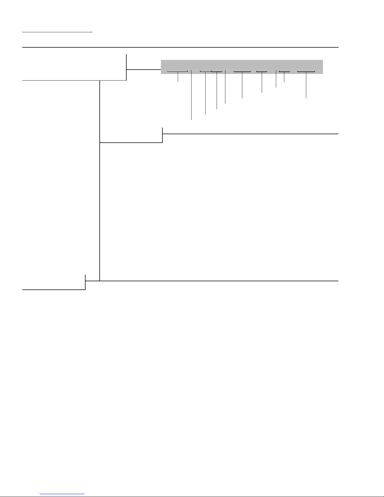
SECTION 2
WILDEN PUMP DESIGNATION SYSTEM
A.025 ORIGINAL™
METAL
6 mm (1/4") Pump
Maximum Flow Rate:
13.3 lpm (3.5 gpm)
MATERIAL CODES
LEGEND
AIR SYSTEM BASE TYPE
B = ADAPTER BLOCK
P = PRO‑FLO
T = TURBO‑FLO™
WETTED PARTS & OUTER PISTON
AA = ALUMINUM /
ALUMINUM
AZ = ALUMINUM / NO
PISTON
HH = ALLOY C / ALLOY C
HZ = ALLOY C / NO PISTON
SS = STAINLESS STEEL /
SZ = STAINLESS STEEL /
CENTER SECTION
PP = POLYPROPYLENE
LL = ACETAL
®
STAINLESS STEEL
NO PISTON
A.025X / XXX X X / XXX / XX / XXX / XXXX
MODEL
DIAPHRAGMS
AIR VALVE
CENTER SECTION
WETTED PARTS & OUTER PISTON
AIR SYSTEM BASE TYPE
AIR VALVE
A = ALUMINUM (Available on
A.025T only)
L = ACETAL (Available for
A.025B and A.025P only)
P = POLYPROPYLENE (Available
for A.025B and A.025P only)
U = UHMW PE (Available for
A.025B only)
DIAPHRAGMS
BNS = BUNA‑N (Red Dot)
TNL = PTFE W/ NEOPRENE BACK‑
UP O‑RING,
IPD (White)
WFS = WIL‑FLEX™ [Santoprene®
(Orange Dot)]
VALVE BALL
TF = PTFE (White)
O-RINGS
VALVE SEAT
VALVE BALLS
VALVE SEAT
A = ALUMINUM
H = ALLOY C
S = STAINLESS STEEL
VALVE SEAT O-RING
BN = BUNA‑N
TF = PTFE (White)
TV = PTFE ENCAP. VITON
WF = WIL‑FLEX™
[Santoprene®]
MANIFOLD O-RING
BN = BUNA‑N
TF = PTFE (White)
SPECIALTY
CODE
(if applicable)
®
SPECIALTY CODES
0150 Accu‑Flo™, 24V DC coil
0151 Accu‑Flo™, 24V AC / 12V DC coil
0153 Accu‑Flo™, 24V AC / 12V DC x‑proof coil
0154 Accu‑Flo™, 24V DC x‑proof coil
0155 Accu‑Flo™, 110V coil
0156 Accu‑Flo™, 110V AC x‑proof coil
0157 Accu‑Flo™, 24V DC x‑proof coil, Intl.,
PTB approved
0169 Accu‑Flo™, 110V AC coil, PFA coated
hardware
0170 Accu‑Flo™, 110V AC x‑proof coil,
PFA coated hardware
0180 Accu‑Flo™, 24V AC / 12V DC coil,
PFA coated hardware
0181 Accu‑Flo™, 24V AC / 12V DC x‑proof coil,
PFA coated hardware
NOTE: MOST ELASTOMERIC MATERIALS USE COLORED DOTS FOR IDENTIFICATION.
THE THREE ACCU-FLO™ OPTIONS AVAILABLE:
1. AxT: This is the same Accu-Flo™ configuration that has been
available from Wilden since March 1994. An aluminum solenoid valve
is attached directly to a T-series center section and the shaft/inner
piston configuration is altered.
2. AxP: This option uses a plastic (polypropylene or acetal) spacer
that is assembled between the Pro-Flo® air valve and the Pro-Flo®
center section. The same solenoid operator – coil assembly that is
found on AxT pumps is assembled on the plastic spacer discussed
above for electronic interface. This spacer together with the Pro-Flo®
air valve replaces the aluminum air valve used in the AxT with a more
chemically resistant option. Spacers will be available in the 1/4",
Viton® is a registered trademark of DuPont Dow Elastomers.
0184 Accu‑Flo™, 24V DC coil, PFA coated
hardware
0185 Accu‑Flo™, 24V DC x‑proof coil,
PFA coated hardware
0675 Accu‑Flo™, 24V DC, inlet manifold,
dual ported, NPT
0676 Accu‑Flo™, 24V DC, inlet manifold,
dual ported, BSPT
1/2", and 1" sizes. The use of the Pro-Flo® ADS provides additional
flow in most applications (refer to EOM for details). The AxP provides
the Pro-Flo® benefits of lower start-up pressure, reduced blow-by,
and increased life.
3. AxB: This option uses an Adapter Block in place of an air valve. A
user supplied, 4-way pneumatic valve must be used in conjunction
with this technology. This configuration enables the solenoid valve to
be remotely installed, preventing chemical attack in very aggressive
environments. Adapter Blocks are available for both the T and Pseries center sections in all pump sizes. (See EOM AxB for details.)
Note: The "x" in the above Accu-Flo™ descriptions are used in place
of a pump model size. See Pump Designation System chart above.
WILDEN PUMP & ENGINEERING, LLC WIL-10030-E-03
2
SECTION 3
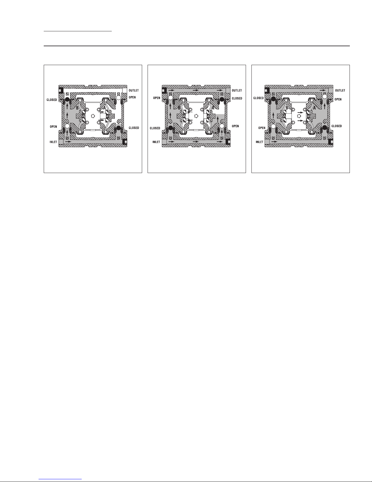
THE WILDEN PUMP — HOW IT WORKS
The Wilden diaphragm pump is an air-operated, positive displacement, self-priming pump. These drawings show the flow
pattern through the pump upon its initial stroke. It is assumed the pump has no fluid in it prior to its initial stroke.
RIGHT STROKE LEFT STROKE RIGHT STROKE
FIGURE 1 When the solenoid is energized, the air valve directs pressure
to the back side of diaphragm A. The
compressed air is applied directly to the
liquid column separated by elastomeric
diaphragms. The diaphragm acts as
a membrane between the compressed
air and the liquid, balancing the load
and removing mechanical stress from
the diaphragm. The compressed
air moves the diaphragm away from
the center section of the pump. The
opposite diaphragm is pulled in by
the shaft connected to the pressurized diaphragm. Diaphragm B is on its
suction stroke; air behind the diaphragm
has been forced out to the atmosphere
through the exhaust port. The movement of diaphragm B toward the center
section of the pump creates a vacuum
within chamber B. Atmospheric pressure forces fluid into the inlet manifold
forcing the inlet valve ball off of its seat.
Liquid is free to move past the inlet
valve ball and fill the liquid chamber (see
shaded area).
FIGURE 2 When the solenoid valve is
deenergized, the air valve redirects pressurized air to the back side of diaphragm
B. The pressurized air forces diaphragm
B away from the center section while
pulling diaphragm A to the center
section. Diaphragm B is now on its
discharge stroke. Diaphragm B forces
the inlet valve ball onto its seat due
to the hydraulic forces developed in
the liquid chamber and manifold of the
pump. These same hydraulic forces lift
the discharge valve ball off of its seat,
while the opposite discharge valve ball is
forced onto its seat, forcing fluid to flow
through the pump discharge. The movement of diaphragm A toward the center
section of the pump creates a vacuum
within liquid chamber A. Atmospheric
pressure forces fluid into the inlet manifold of the pump. The inlet valve ball is
forced off of its seat allowing the fluid
being pumped to fill the liquid chamber.
FIGURE 3 Once the solenoid valve is
reenergized the air is directed to the
back side of diaphragm A, which starts
diaphragm B on its exhaust stroke. As
the pump reaches its original starting
point, each diaphragm has gone through
one intake and one discharge stroke.
This constitutes one complete pumping cycle. The pump may take several
cycles to completely prime depending
on the conditions of the application.
3
WILDEN PUMP & ENGINEERING, LLCWIL-10030-E-03
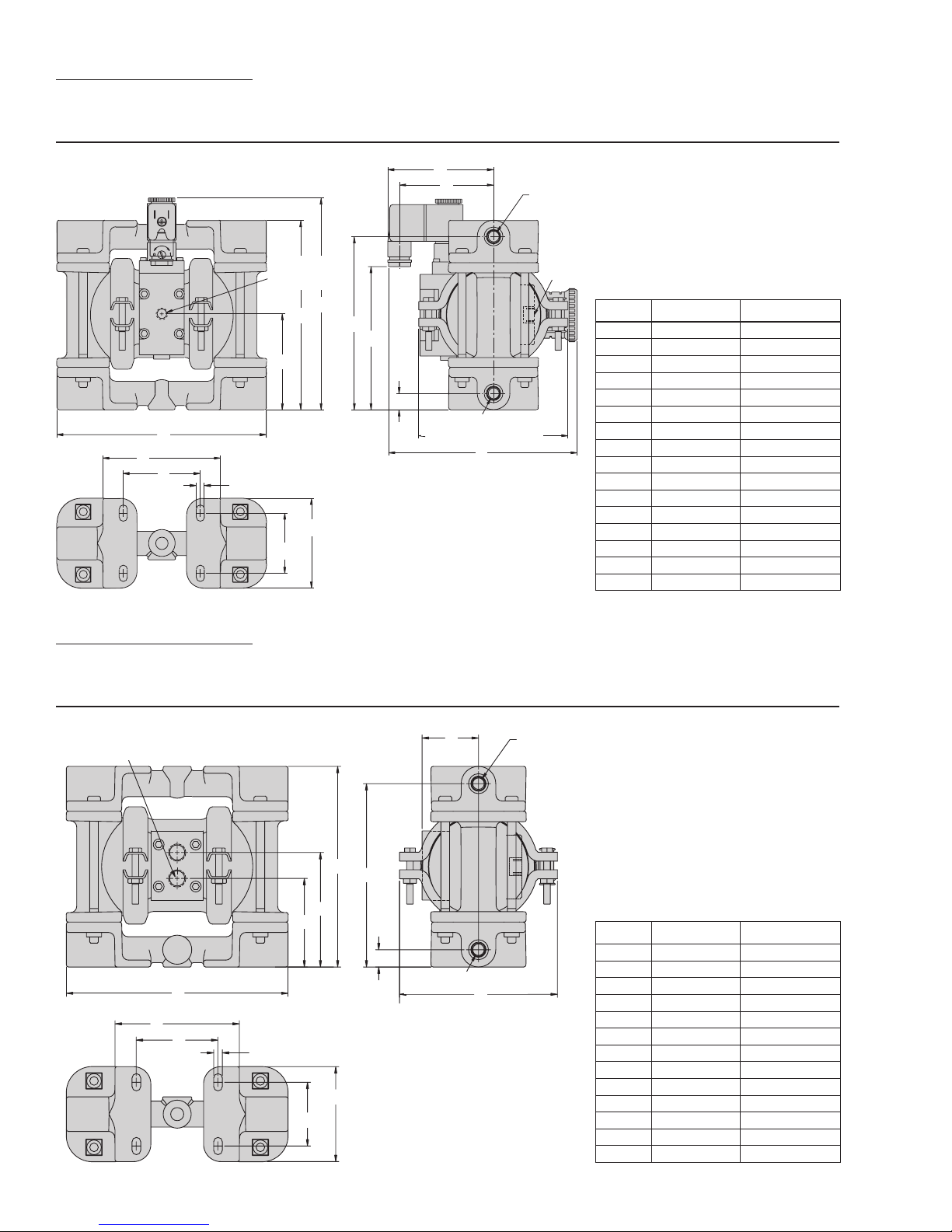
SECTION 4A
DIMENSIONAL DRAWING
A.025T METAL ACCU-FLO™
6 mm (1/4”)
K
6 mm (1/4”)
BSP (FNPT)
LIQUID
DISCHARGE
6 mm (1/4”)
BSP (FNPT)
AIR EXHAUST
DIMENSIONS
ITEM METRIC (mm) STANDARD (inch)
A 165 6.5
B 74 2.9
C 147 5.8
D 140 5.5
E 135 5.3
F 107 4.2
G 13 0.5
H 97 3.8
J 74 2.9
K 114 4.5
L 91 3.6
M 61 2.4
N 8 0.3
P 46 1.8
R 71 2.8
S 147 5.8
H
J
3 mm (1/8”)
BSP (FNPT)
AIR INLET
D
C
B
A
L
M
N
P
E
F
G
BSP (FNPT) LIQUID INLET
S
R
SECTION 4B
DIMENSIONAL DRAWING
A.025B METAL (T-SERIES CENTER SECTION)
6 mm (1/4”)
BSP (FNPT) AIR INLET
A
K
L
D
F
C
B
G
M
P
N
E
6 mm (1/4”)
BSP (FNPT) LIQUID INLET
H
6 mm (1/4”) BSP (FNPT) LIQUID
DISCHARGE
DIMENSIONS
ITEM METRIC (mm) STANDARD (inch)
A 165 6.5
B 66 2.6
C 84 3.3
D 147 5.8
E 41 1.6
F 135 5.3
G 13 0.5
H 114 4.5
K 91 3.6
L 61 2.4
M 8 0.3
N 46 1.8
P 71 2.8
WILDEN PUMP & ENGINEERING, LLC WIL-10030-E-03
4
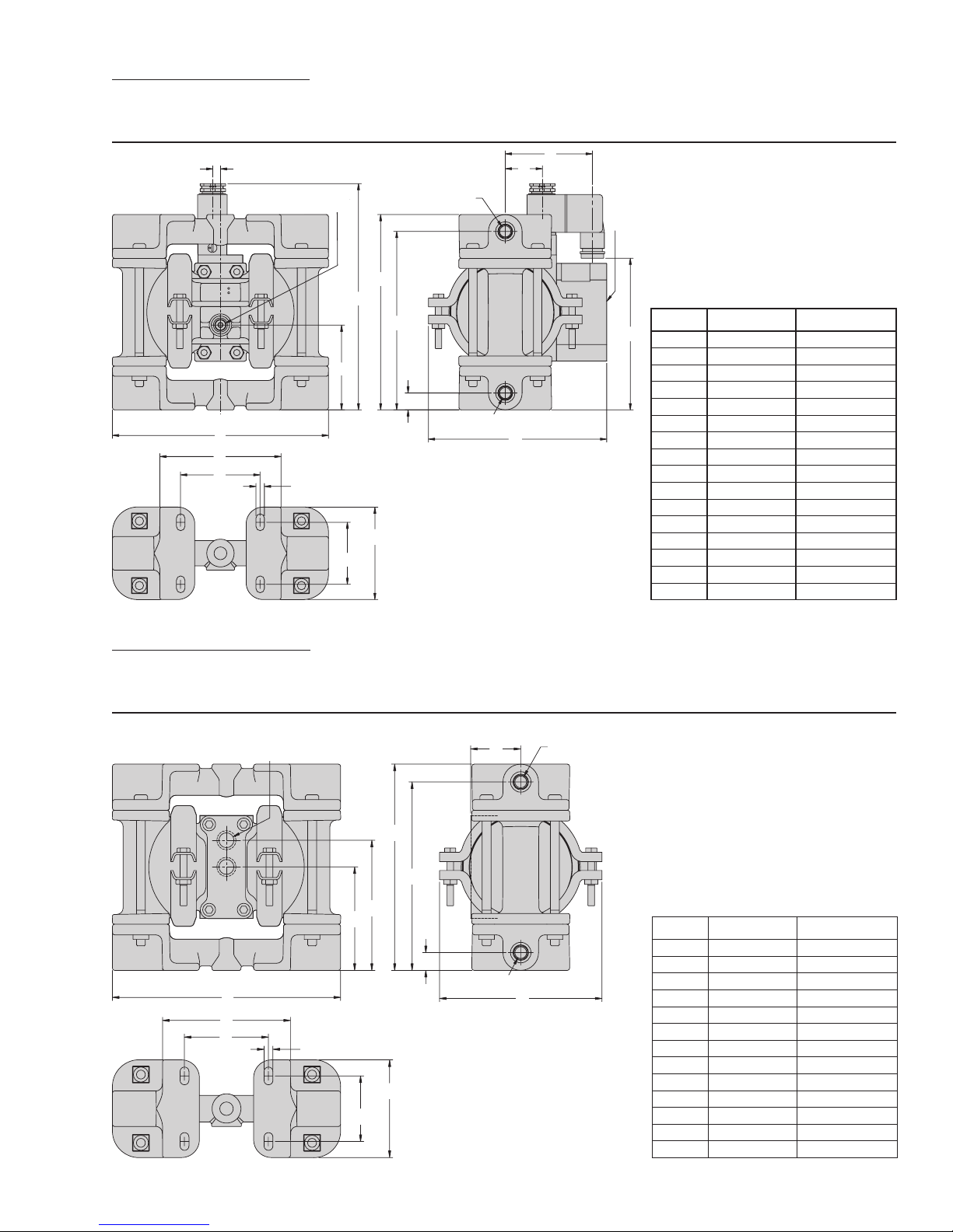
SECTION 4C
DIMENSIONAL DRAWING
A.025P METAL ACCU-FLO™
J
D
A
M
N
6.35 mm (1/4”)
3 mm (1/8”)
BSP (FNPT) AIR INLET
AIR INLET
P
6 mm (1/4”)
BSP (FNPT)
LIQUID DISCHARGE
E
C
F
B
G
6 mm (1/4”) BSP (FNPT) LIQUID
S
R
H
INLET
L
EXHAUST
DIMENSIONS
ITEM METRIC (mm) STANDARD (inch)
K
A 165 6.5
B 64 2.5
C 170 6.7
D 8 0.3
E 147 5.8
F 135 5.3
G 13 0.5
H 28 1.1
J 66 2.6
K 114 4.5
L 135 5.3
M 91 3.6
N 61 2.4
P 8 0.3
R 46 1.8
S 71 2.8
SECTION 4D
DIMENSIONAL DRAWING
A.025B METAL (P-SERIES CENTER SECTION)
6 mm (1/4”)
BSP (FNPT) AIR INLET
A
J
K
G
D
E
C
B
F
6 mm (1/4”) BSP (FNPT)
L
M
N
6 mm (1/4”) BSP (FNPT)
LIQUID DISCHARGE
LIQUID INLET
HH
DIMENSIONS
ITEM METRIC (mm) STANDARD (inch)
A 165 6.5
B 74 2.9
C 94 3.7
D 147 5.8
E 135 5.3
F 13 0.5
G 36 1.4
H 114 4.5
J 91 3.6
K 61 2.4
L 8 0.3
M 71 2.8
N 46 1.8
5
WILDEN PUMP & ENGINEERING, LLCWIL-10030-E-03
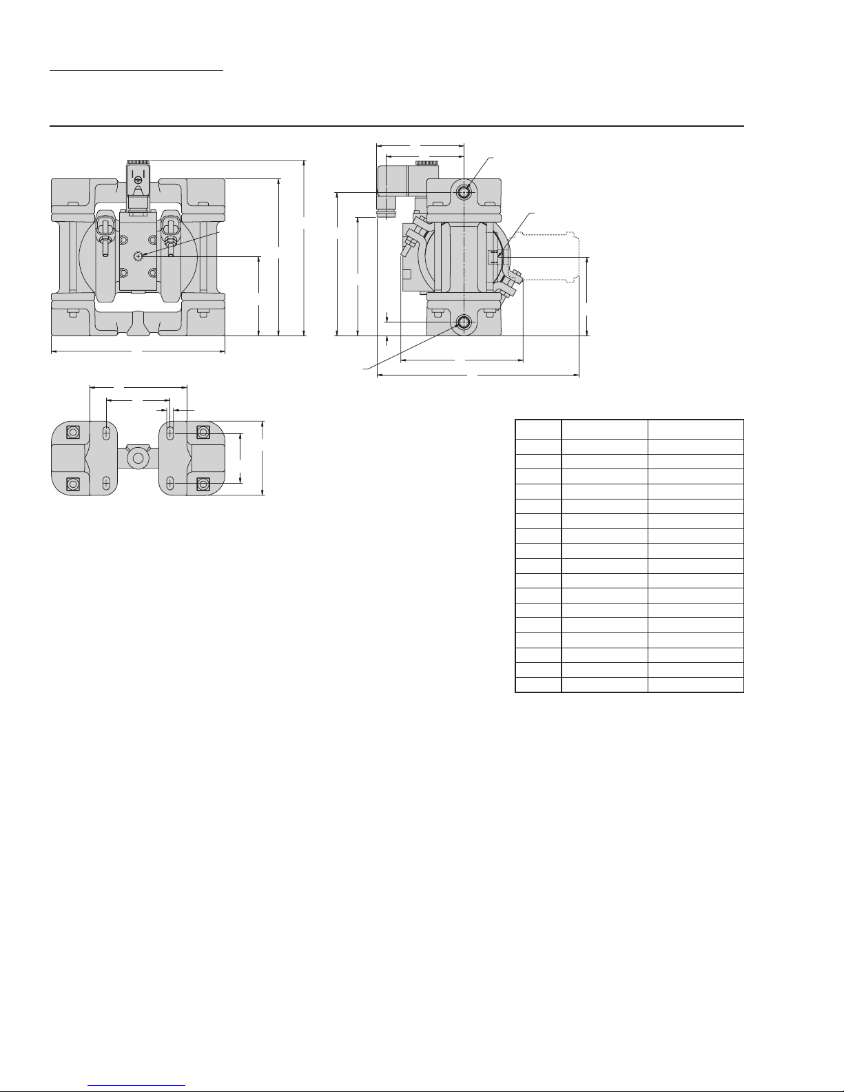
SECTION 4E
DIMENSIONAL DRAWING
XA.025T METAL (T-SERIES CENTER SECTION)
H
J
C
D
LIQUID INLET
E
F
G
3.18 mm (1/8”)
FNPT AIR INLET
B
A
6.35 mm (1/4”) BSP (FNPT)
L
M
N
R
P
6.35 mm (1/4”)
BSP (FNPT) LIQUID DISCHARGE
K
S
DIMENSIONS
6.35 mm (1/4”)
FNPT AIR EXHAUST
ITEM METRIC (mm) STANDARD (inch)
A 165 6.5
B 74 2.9
C 147 5.8
D 165 6.5
E 135 5.3
F 107 4.2
G 13 0.5
H 97 3.8
J 74 2.9
K 114 4.5
L 91 3.6
M 61 2.4
N 8 0.3
P 46 1.8
R 71 2.8
S 191 7.5
T 74 2.9
T
WILDEN PUMP & ENGINEERING, LLC WIL-10030-E-03
6
SECTION 5A
PERFORMANCE
A.025T METAL RUBBER-FITTED
Height ....................................140 mm (5.5")
Width
.....................................165 mm (6.5")
Depth
....................................147 mm (5.8")
Est. Ship Weight
Stainless Steel 5 kg (11 lbs)
Alloy C 5 kg (12 lbs)
Air Inlet ..................................... 3 mm (1/8")
Inlet
.......................................... 6 mm (1/4")
Outlet
....................................... 6 mm (1/4")
Suction Lift
10.02 m (32.9' Wet)
Displacement per stroke
...........................................0.24 l (.006 gal.)
Max. Flow Rate
Max. Size Solids
Example: To pump 3.8 lpm (1 gpm) against a
discharge pressure head of 3.6 bar (52 psig)
requires 4.1 bar (60 psig) and 2.7 Nm
scfm) air consumption.
Caution: Do not exceed 8.6 bar (125 psig) air
supply pressure.
......... Aluminum 2 kg (5 lbs)
...................... 5.36 m (17.6' Dry)
...............16.3 lpm (4.3 gpm)
.................. 0.4 mm (1/64")
3
/h (1.6
[LPM]
Flow rates indicated on chart were determined by pumping water.
For optimum life and performance, pumps should be specified so that daily operation parameters
will fall in the center of the pump performance curve.
[Nm3/h]
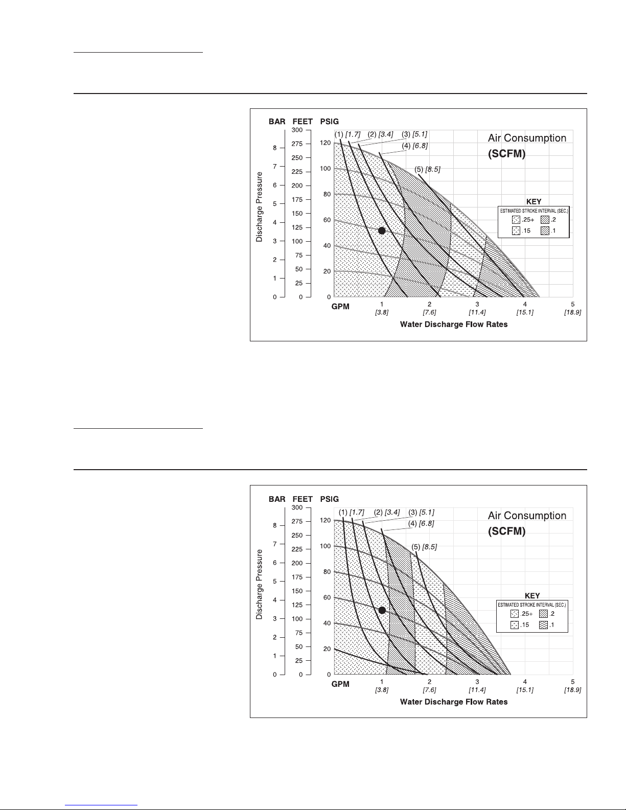
SECTION 5B
PERFORMANCE
A.025T METAL PTFE-FITTED
Height ....................................140 mm (5.5")
Width
.....................................165 mm (6.5")
Depth
....................................147 mm (5.8")
Est. Ship Weight
Stainless Steel 5 kg (11 lbs)
Alloy C 5 kg (12 lbs)
Air Inlet ..................................... 3 mm (1/8")
Inlet
.......................................... 6 mm (1/4")
Outlet
....................................... 6 mm (1/4")
Suction Lift
10.02 m (32.9' Wet)
Displacement per stroke
.........................................0.017 l (.005 gal.)
Max. Flow Rate
Max. Size Solids
Example: To pump 3.8 lpm (1 gpm) against a
discharge pressure head of 3.4 bar (50 psig)
requires 4.1 bar (60 psig) and 4.08 Nm
(2.4 scfm) air consumption.
Caution: Do not exceed 8.6 bar (125 psig) air
supply pressure.
......... Aluminum 2 kg (5 lbs)
..................... .4.32 m (14.2' Dry)
...............14.0 lpm (3.7 gpm)
................. .0.4 mm (1/64")
3
/h
Flow rates indicated on chart were determined by pumping water.
For optimum life and performance, pumps should be specified so that daily operation parameters
will fall in the center of the pump performance curve.
[Nm3/h]
[LPM]
7
WILDEN PUMP & ENGINEERING, LLCWIL-10030-E-03
 Loading...