

Wildeboer FR90 User Manual
Maintenance-free
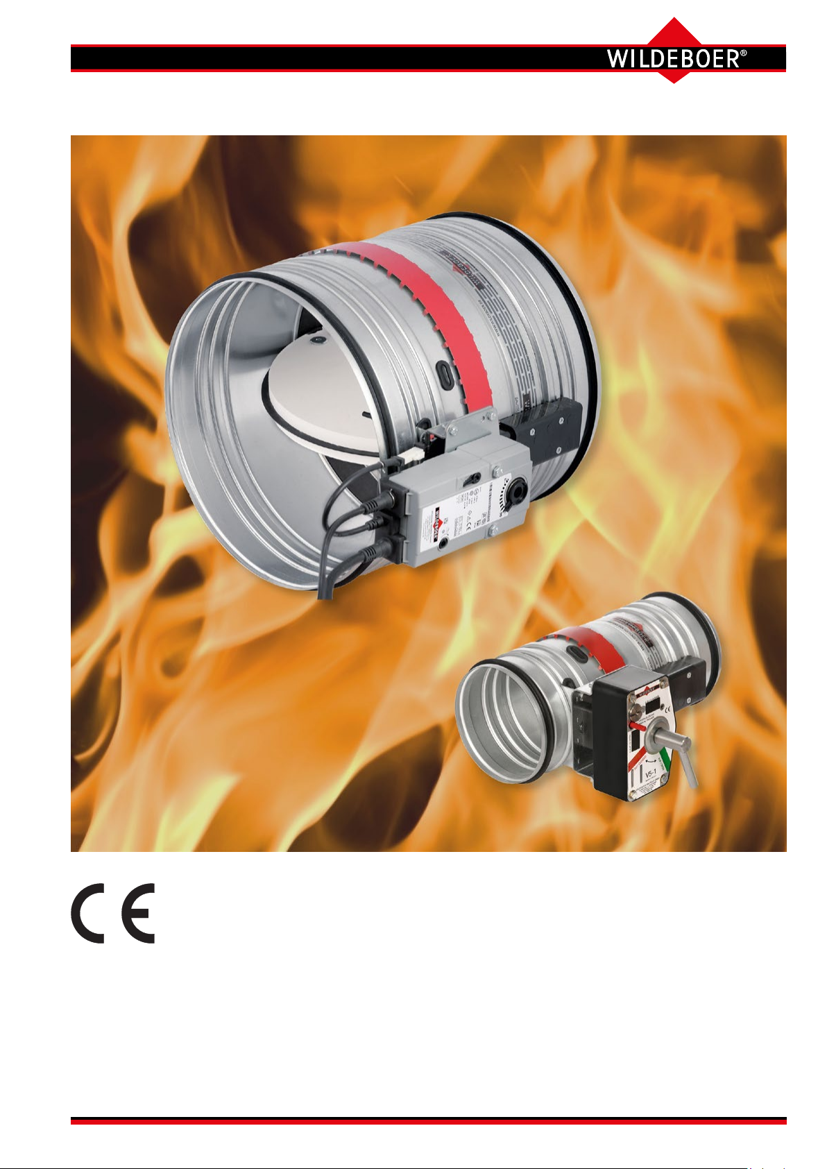
FR90 re dampers
■ Sizes ∅ 100 mm to ∅ 800 mm
■ For universal use with a wide range of applications
■ Fire classication: EI 30/60/90/120 (ve - ho, i ↔ o) S C
■ Hygiene certicate
■ Environmental Product Declaration according to ISO 14025 and EN 15804
The German original version of this document shall prevail
10ooo
User Manual 5.3 (2018-07) 1

FR90 re dampers
Features and characteristics
Single-piece sheet steel casing
galvanized - longitudinal seam welded - extremely robust
airtight, smoke-proof
Leak tightness class C
according to EN 1751
Option: Epoxy resin powder coating
Nominal sizes [mm]
DN 100 to DN 800
Break-resistant
damper blade
with elastomer lip seal
airtight, leak tightness class 3
according to EN 1751
Options:
• Metal cover made of galvanized steel
• Metal cover made of 1.4301 stainless steel
Two control openings (inspection openings)
for viewing both sides of the damper blade
Lip seals
Large free cross-section
Maximum volume ows
Minimum pressure drop
Extremely low sound power level
Release mechanism and axis of
the damper blade rotatable 360°
Fully enclosed:
• Operation unit
• Release mechanism
• Release element
Thermal-mechanical
release mechanism
for single handed operation
Option:
Electric actuators, also explosion-protected
All-round enclosed
thermal release elements 70°C or 95°C
Option:
Corrosion-resistant release element 70°C
User Manual 5.3 (2018-07) 2 Subject to change
Series FR92

FR90 re dampers
Description
Maintenance-free FR90 re dampers according to EN 15650
Fire classications: EI 30/60/90/120 (v
- ho, i ↔ o) S C
e
10ooo
Declaration of performance: DoP no.: CPR/FR90/003
EU Declaration of Conformity according to Directive 2014/34/EU for
use in potentially explosive atmospheres
Environmental Product Declaration ISO 14025, EN 15804:
EPD-WWB-20130082-IBA1-DE
All-round single-piece galvanized sheet steel casing.
Casing tightness class C according to EN 1751.
Moulded push-t connections with lip seals for spiral
duct according to DIN 24145, for exible pipe and for
similar ducts of ventilation and air conditioning systems.
All-round press-moulded beading over the whole length
of casing ensures necessary strength and free movement of the damper blade even with large dimensions.
Low pressure drop and a very low noise level are thus
achieved.
Replaceable damper blade made of high-temperature-resistant, abrasion-proof calcium silicate with
wear-resistant elastomer seals. Damper blade leak tightness class 3 according to EN 1751.
Option: Casing with powder coating. ⇒ see page 6
Option: Damper blade with metal cover (not replaceable)
made of galvanized steel or 1.4301 stainless steel.
Enclosed, maintenance-free drive mechanism in the
area of the casing wall as a self-locking transmission
for break-proof torque transmission. Sealed drive axles
made of stainless steel, with red metal bearings. Thermal release mechanisms for 70°C or 95°C nominal temperature. The operation units can be actuated manually
or electrically. ⇒ see pages 4 and 5
Release mechanisms, operation units and electric actuators are enclosed and with a spring return. They are
maintenance-free, can be connected in a form-locking
or force-tting manner, are easy to replace and can be
easily retrotted as required.
For installation with horizontal or vertical damper blade
axles and in intermediate positions. Air ows are possible from each connection side.
Connection to ventilation ducts made from non-combustible or combustible materials is possible, also protective
grille.
Installation spacings from 15 mm possible.
Additional national approvals in
Germany:
• Building materials: Z-56.4212-993
FR90 re dampers are essentially
made from non-combustible building materials.
• Air transfer applications:
Z-6.50-2133
Z-19.18-2241
Nominal sizes [mm] DN:
100 - 125 - 140 - 160 - 180 - 200 - 224 - 250 - 280 - 315 - 355 - 400 - 450 - 500 - 560 - 630 - 710 - 800
FR90 re dampers in these sizes achieve re resistance periods of up to 120 minutes if they are installed in accordance with
the following stipulations. Installation types in, on or remote from rigid walls and ceilings or metal stud walls, in wooden walls and
ceilings and in ceilings with steel frames with a minimum thickness and re resistance period. If the walls, ceilings have a re
resistance period of less than 120, 90 or 60 minutes, the re resistance period of the FR90 re dampers is reduced accordingly;
partly if the minimum thickness is lower.
Options:
• Circular installation subframe RR (RR100, RR150) for
simplied installation in circular installation openings.
Only up to DN 315! ⇒ see pages 7, 8, 13, 14, 22, 42 to 44
•
Rectangular installation subframe RE (RE100,
RE150) for simplied installation in rigid walls and
ceilings and in metal stud walls with cladding on both
sides.
⇒ see pages 7, 8, 13, 14, 20 to 22, 42 to 44
• With rectangular installation subframe RH (RH100,
RH150) for installation in wooden walls and wooden
ceilings. ⇒ see pages 7, 8, 28 to 31, 42 to 45
• Rectangular installation subframe RH150 for installation in ceilings with steel frames.
⇒ see pages 7, 8, 33, 34, 42 to 45
• Mounting frame AE for mounting on rigid walls and
ceilings and walls with cladding on one side and with
or without metal studs.
⇒ see pages 7, 8, 15, 26, 27, 35, 42 to 44
• Installation subframe ER6 for sliding ceiling connec-
tions with drops of up to 40 mm in metal stud walls
with cladding on both sides.
⇒ see pages 7, 8, 23 to 25, 42, 43
• Mounting frame RV for connection to ventilation
ducts with re resistance period. Installation remote
from rigid walls and ceilings and metal stud walls.
⇒ see pages 7, 8, 36 to 39, 42 to 45
Series FR92
User Manual 5.3 (2018-07) 3Subject to change
FR90 re dampers
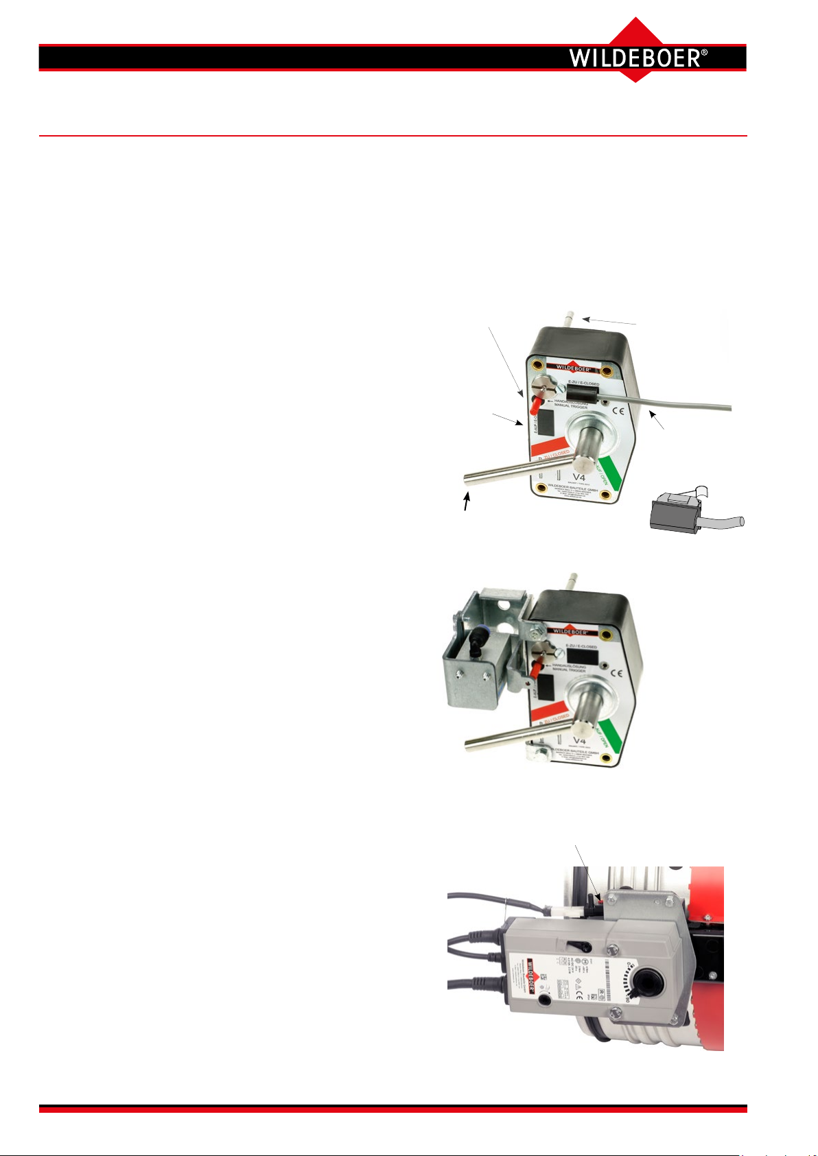
Release mechanisms and actuators (1)
FR90 re dampers, series FR92, are tted with maintenance-free thermal-mechanical release mechanisms or with
thermal-electrical release mechanisms on the spring return actuators. Release occurs at a nominal temperature of
70°C or 95°C. Coated release elements provide increased corrosion protection.
Electric spring return actuators also close the re dampers if the supply voltage is interrupted. They reopen the re
dampers as soon as the voltage is present again.
Release mechanisms and operation units can be replaced on site!
Thermal-mechanical release mechanism - Standard -
with 70°C release element, protection class IP54.
Option: with coated 70°C release element.
Option: with coated 95°C release element.
Option: with limit switch
E Changeover with gold-plated contacts for 5 A at
250 V AC or 24 V DC; protection class IP67;
1 m silicone free connection cable 3 x 0.34 mm².
One or two can be plugged in for the CLOSED and/or OPEN
position indicator instead of blind caps.
Option: with additional remote release based on the:
closed circuit principle. The re dampers must be opened man-
ually, and close after the electrical supply voltage is interrupted.
WU220 with magnetic clamp 230 V AC; 4 VA;
GU24 with magnetic clamp 24 V DC; 1.6 W;
100% duty cycle; IP42.
100% duty cycle; IP42.
Open circuit principle. The re dampers must be opened man-
ually, and close by means of electrical or pneumatic stimulus.
P with lift cylinder 4 to 8 bar.
P2 with lift cylinder 1.2 to 8 bar.
G24 with lifting solenoid 24 V DC; 3.5 W; 100% duty
cycle; IP42.
W220 with lifting solenoid 230 V AC; 5.5 VA; 100% duty
cycle; IP42.
Manual release
“Red button”
Blind cap can
be replaced with
the OPEN limit
switch.
Lever for opening
the re damper.
Release mechanism and remote release with lift cylinder
Button for function check
Enclosed release
element can be
replaced from the
front.
Inserted
CLOSED limit
switch.
Option: Electric spring return actuator - Standard up to DN 315 -
only for sizes DN ≤ 315 mm
with 70°C release element; protection class IP54.
M220-10/F 230 V AC; 6.5 VA / 3 W; I
M24-10/F 24 V AC/DC; 4 VA / 2.5 W; I
Runtime: Opening < 60 s, closing ≈ 20 s
CLOSED/OPEN position indicators via limit switches for 0.5 A
at ≤ 250 V AC or for 1 mA up to 3 A at 5 up to 250 V DC.
Halogen-free connection cable; 1 m long; 2 x 0.75 mm² and
6 x 0.75 mm². The AMP connector plugs are detachable.
Option: with 95°C release element.
User Manual 5.3 (2018-07) 4 Subject to change
max ≤ 5 ms
max ≤ 5 ms
= 4 A
= 8.3 A
Figure shows M220-10/F or
M24-10/F.
Series FR92
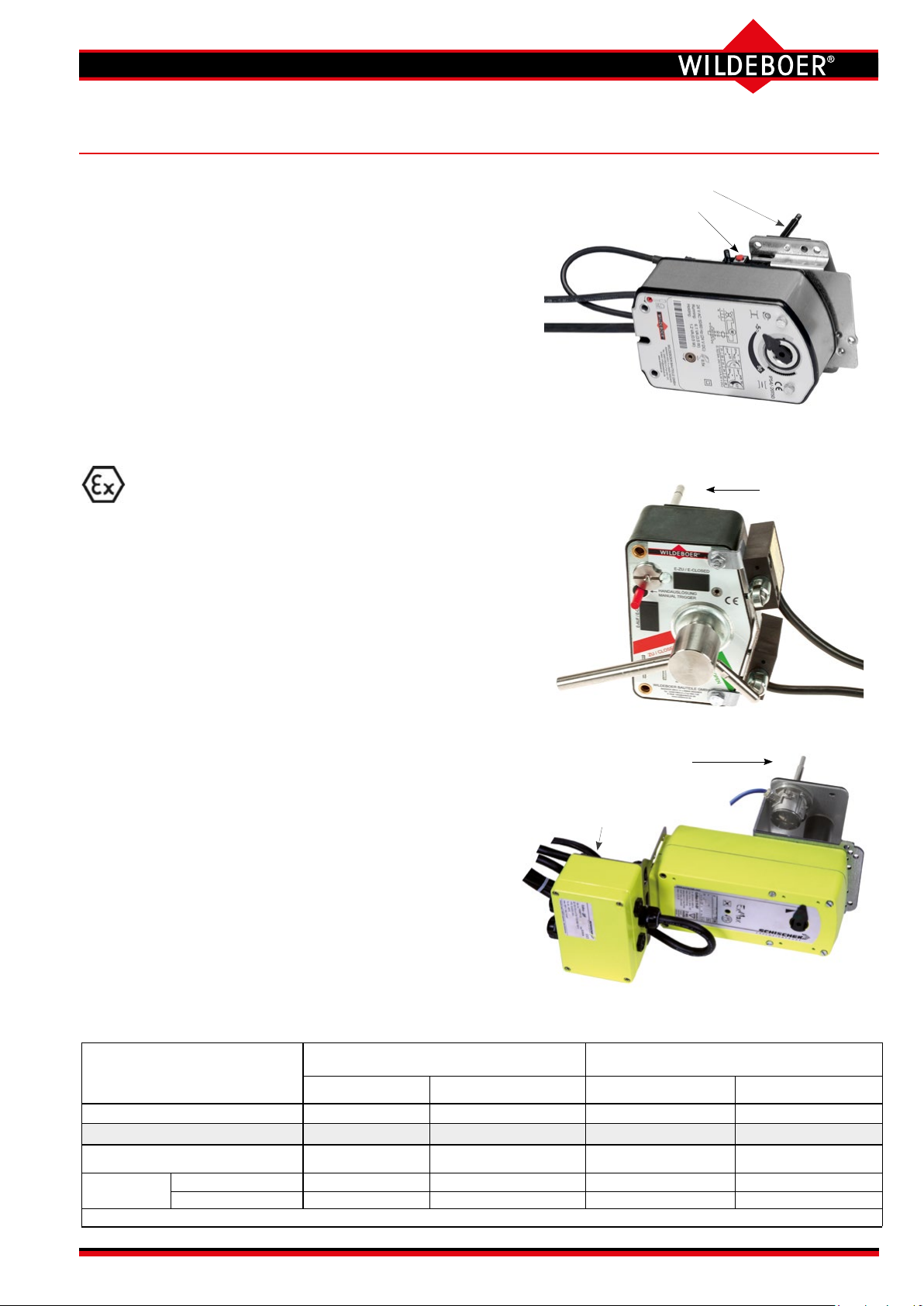
FR90 re dampers
Release mechanisms and actuators (2)
Option: Electric spring return actuator
- Standard from DN 355 -
with 70°C release element; protection class IP54.
M24-9/H 24 V AC/DC; 6.1 VA / 3.5 W; I
Runtime: Opening ≈ 60 s, closing ≈ 21 s.
CLOSED/OPEN position indicators via limit switch for
Halogen-free connection cable; 0.9 m long;
Option: with 95°C release element.
M220-9/H 230 V AC; 9,2 VA; I
max ≤ 2 ms
= 0.27 A.
max ≤ 2 ms
= 3.5 A.
5 A at ≤ 240 V AC.
2 x 0.75 mm² and 6 x 0.75 mm². The AMP connector
plugs are detachable.
- designs
Thermal-mechanical release mechanism
with 70°C release element; protection class IP54.
Option: with coated 70°C release element.
Option: with explosion-protected limit switch
E-Ex with normally open contact and normally closed
contact for 6 A at ≤ 250 V AC or 0.25 A at
≤ 230 V DC; protection class IP65;
2 m connection cable 4 x 0.75 mm².
One or two can be attached for the CLOSED and/or OPEN
position indicator.
Option: Electric spring return actuator
with 70°C release element and terminal box.
EM-1 10 Nm
EM-2 15 Nm
24 to 240 V AC/DC;
protection class IP66.
}
RM-1 10 Nm
Power consumption up to 20 W including heating;
I
nominal
≤ 0.7 A; I
max ≤ 1 s
≈ 2.5 A
Runtime: Opening ≈ 30 s, closing ≈ 10 s.
CLOSED and OPEN position indicators via limit
switches for ≤ 3 A at 24 V AC/DC and ≤ 0.25 A at
250 V AC/DC;at least 5 V, 10 mA.
The 12 x 0.5 mm² halogen-free connection cable must be wired in
the terminal box! All of the contained voltages must be the same!
Use of explosion-protected designs
Enclosed release element
Button for function check
Enclosed
release element
Enclosed release element
Terminal box
The actuators can be rotated into
suspended and vertical positions on site.
... as a mixture of air and
Building area where a dangerous, potentially explo-
sive atmosphere may occur in normal operation...
Zone 1 2 21 22
Identication of the re damper II 2 G c IIc T6/T5 II 3 G c IIc T6/T5 II -/2 D c T80°C/T95°C II -/3 D c T80°C/T95°C
Thermal-mechanical release mechanism with or
without explosion-protected limit switch
Motor drive
Ambient temperatures: -20 … +40°C for T6 and T80°C/-20 … +50°C for T5 and T95°C *) Also to be used in this zone!
EM-1 or EM-2 X X
RM-1 - X - X
... can form occasionally. ... occurs temporarily or not at all. ... can form occasionally. ... occurs temporarily or not at all.
combustible gases, mists or vapours...
X X *
)
)
*
Series FR92
... in the form of a cloud of
combustible dust contained in the air...
X X
X X
User Manual 5.3 (2018-07) 5Subject to change
)
*
)
*
FR90 re dampers
Powder coating/hygiene /installation positions
Option: Powder coating
For FR90 re damper casings with inner and outer epoxy resin coating
• damper blades with metal cover made of 1.4301 stainless steel
• thermal-mechanical release mechanisms with corrosion-resistant (coated) release element 70°C
should be used. This allows for additional corrosion protection for higher stresses.
FR90 re dampers
• meet the hygiene requirements according to VDI 6022-1, VDI 3803-1, DIN 1946-4, DIN EN 13779
• do not promote the growth of microorganisms 1) (fungi, bacteria). This
reduces the risk of infection for people and also the necessary cleaning and
disinfection work!
• are resistant to disinfectants 2)
• are suitable for use in hospitals and similar facilities!
•
permanently perform their function under high corrosion conditions.
Tested according to EN 15650, annex B with 20% saline solution.
1)
The corresponding resistance of the materials to fungi and bacteria has been veried by testing the microbial metabolic potential according to
DIN EN ISO 846 for all materials in the FR90 re dampers.
2)
The resistance to disinfectants of the materials in the FR90 re dampers was tested with the disinfectant groups of active ingredients alcohol and
quaternary compounds. These disinfectants are on the list by the Robert Koch Institute, and were used in accordance with the specications in
the list of disinfectants by the Disinfectants Commission in the German Association for Applied Hygiene (VAH). It has been veried that FR90 re
dampers can withstand normal use of disinfectants and disinfection methods.
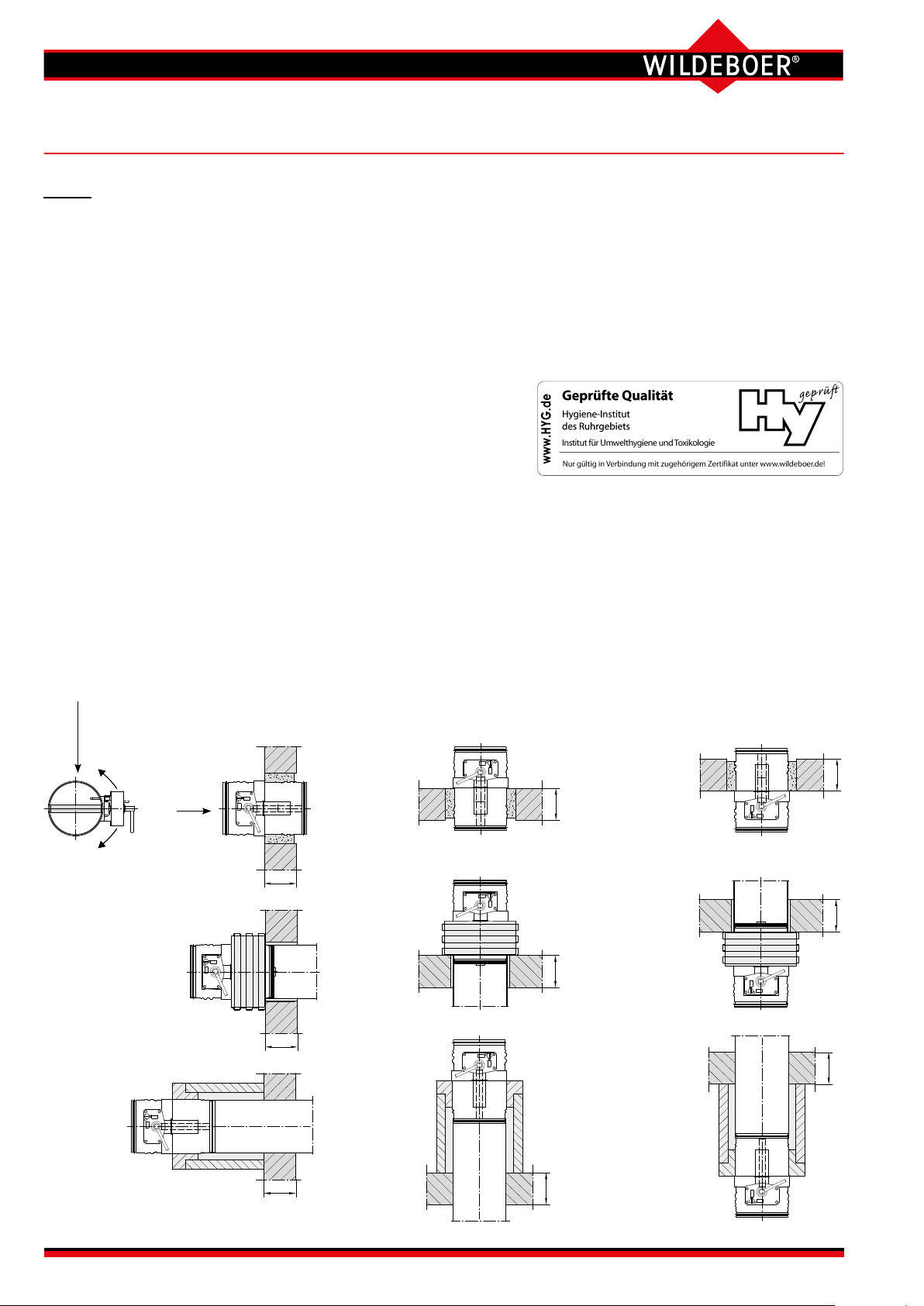
Installation positions
Damper blade axle and drive can be installed
to rotate up to 360°!
Horizontal installation positions W = wall
Operation side
Visible side
Installation in walls
Installation
directly on walls
W
W
Vertical installation positions D = ceiling
Non-operation side
Vertical installation in ceilings
Installation directly on ceilings
D
Installation in suspended position ceilings
D
Installation directly under ceilings
Installation remote from
and above ceilings
D
D
D
W
Installation remote from walls
User Manual 5.3 (2018-07) 6 Subject to change
Series FR92
D
Installation remote from
and below ceilings
FR90 re dampers
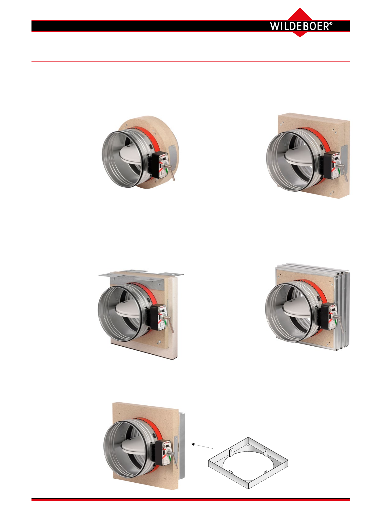
Installation subframes/mounting frames
With circular installation subframe RR100 or RR150
for simplied installation in circular openings such as
core holes in rigid walls and ceilings or holes in metal
stud walls with cladding on both sides.
Only up to DN 315!
⇒ see pages 8, 13, 14, 22,
42 to 44
With installation subframe ER6 made from calcium
silicate for sliding ceiling connections with a drop of
up to 40 mm in metal stud walls with cladding on both
sides.
The drop can be
single or recurring
(settlement and
changing loads).
⇒ see pages 8,
23 to 25
, 42, 43
Rectangular installation subframe RE100 or RE150
made of calcium silicate for simplied – also multiple –
installation in rigid walls and ceilings and in
walls
with cladding on both sides.
⇒ see pages 8, 13, 14, 20 to 22, 42 to 44
metal stud
With rectangular instal-
lation subframe
RH100 or RH150
made of calcium silicate for dry instal-
lation in wooden
walls and in wooden
ceilings
⇒ see pages 8, 28 to 31,
42 to 45
With rectangular installation
subframe RH150 for installation in ceilings with steel
frames.
⇒ see pages 8, 33, 34, 42 to 45
With mounting frame AE made of calcium silicate
for mounting on rigid walls and ceilings and on walls
with cladding on one side
(shaft walls) and with
and without metal
studs.
⇒ see pages 8, 15, 26,
27, 35,
42 and 44
With Mounting frame RV for connection to ventilation
ducts with re resistance period.
Particularly for installation remote from rigid walls and ceilings
and from metal stud walls with
cladding on both sides.
⇒ see pages 8,
36 to 39, 42 to 45
Series FR92
Accessories for mounting frame:
Connecting frame for attaching the ventilation duct
with re resistance period to walls and ceilings.
⇒ see pages 8, 36 to 39, 42 to 44
Featured: Size for DN ≤ 315
User Manual 5.3 (2018-07) 7Subject to change
L2
Control opening
Limit switch
E-OPEN (optional)
Control opening
Limit switch
Lip seal
Mounting frame AE
Installation subframe ER6 (only available assembled)
Mounting frame RV
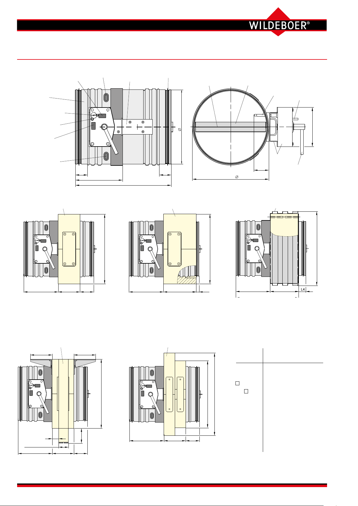
FR90 re dampers
Data sheet (1)
E-CLOSED (optional)
Casing
Thermal-mechanical
release mechanism
Manual release
L1
L2
Installation subframe RR / RE / RH (100mm long)
RR
□ RE/RH
Enclosed transmission
L1
L
Installation subframe RR / RE / RH (150mm long)
Damper bladeDamper blade seal
Release element
1D
50
Outer dimension = DN+8
RR
□ RE/RH
Manual release
231
Operation unit
Manual lever
□ AE
L2
100
L3
With installation subframe RR100, RR150 (circular) or RE100, RE150,
RH100, RH150 (rectangular)
Installation lengths 100 mm and 150 mm.
⇒ see pages 3, 7, 13, 14, 20 to 22, 28 to 34, 42 to 44
101 101
Stud profile
depths S:
50 to 125 mm
L2 100 L3
30
68
With installation subframe ER6
⇒ see pages 3, 7, 23 to 25, 42, 43
□ RE
L2
With mounting frame RV
⇒ see pages 3, 7, 36 to 39, 42 to 45
150
100 L3
L6
□ DN + 59
□ DN + 130
L2
128
L5
With mounting frame AE
⇒ see pages 3, 7, 15, 26, 27, 35, 42 to 44
DN from 100 355
to 315 800
Ø D1 DN - 1 DN - 1
Ø RR DN + 99 -
RE/RH DN + 89 DN + 99
AE DN + 110 DN + 120
L 320 340
L1 40 50
L2 155 160
L3 65 80
L4 37 52
L5 283 288
L6 15 30
All dimensions in mm
User Manual 5.3 (2018-07) 8 Subject to change
Series FR92
FR90 re dampers
Data sheet (2)
Maximum excess lengths of mechanical and electrical equipment parts.
Additional space must be provided for
assembly, electrical connections and maintenance; observe the cable entry points!
In addition to the "T" measurement,
it is recommended that a distance of
400 mm be kept from adjacent walls,
ceilings or other re dampers, in order
to ensure that the release mechanisms
and actuators can be accessed for
operational purposes.
Damper blade
Operation side: X
Non-operation side: Y
Actuators
U Horizontal (delivery condition)
J Vertical
J3
EM-1, RM-1, EM-2
Rotated to vertical or suspended
position
J4
M220-11/H, M24-11/H
rotated to suspended position
J3
J3, J4
U
X
L
Y
DN T
Size-independent
excess lengths
T U
Thermal-mechanical
release mechanism 130 -
with: • W220, WU220 155
• G24, GU24 155 -
• P, P2 140 -
• E-Ex limit switch 140 -
M220-9/H, M24-9/H 125 60
M220-10/F, M24-10/F 85 80
M220-11/H, M24-11/H 110 110
EM-1, EM-2, RM-1 310 216
Size-dependent excess lengths
DN Ø D1 L J3 J4 X Y
100 99 320 220 160 - 125 124 320 210 150 - 140 139 320 200 140 - 160 159 320 190 130 - -
180 179 320 180 120 - -
200 199 320 170 110 - 224 223 320 160 100 - -
250 249 320 150 90 - 10
280 279 320 130 70 - 25
315 314 320 115 55 - 43
355 354 340 95 35 - 52
400 399 340 70 10 - 75
450 449 340 45 - 12 100
500 499 340 20 - 37 126
560 559 340 - - 68 156
-
630 629 340 - - 104 192
710 709 340 - - 144 233
800 799 340 - - 190 279
Operating area, closing and opening
• FR90 re dampers are quick-closing, apart from the versions with electric
actuators. Due to the ow dynamics, if the re damper is triggered at high
inow velocities, this may cause pressure surges accompanied by multiplication of operating pressures, which in turn may lead to considerable damage
to the ventilation and air conditioning system. When shut-o dampers are
closed, the volume ows are distributed to other parallel dampers that are still
open. This may lead to excessive stress, in particular at high operating pressures, large volume ows and large cross-sections. Electric actuators should
be used under such conditions. They close re dampers relatively slowly. In
addition, the fan switch-o can also be triggered via the OPEN limit switch.
• The application limits marked in the nomograms must be complied with!
⇒ see page 9
• For large re dampers that are subjected to an unfavourable ow, actuators
with large torques may be necessary in order to open the re dampers when
the fan is running and there are very large volume ows. These actuators are
available on request. Alternatively, it is also possible to switch on the fans
once the re dampers are fully open.
• It must be ensured that the inows and outows are as equal as possible.
• FR90 Fire dampers with electric actuator can be used for OPEN/CLOSED
volume ow control.
Thermal-mechanical release mechanisms are marked with V3-1, V4,
V5-1. The allocations dependent on DN nominal sizes must not be changed!
DN
≤ 200 V5-1
≥ 224 up to ≤ 315 V3-1
≥ 355 V4
All dimensions in mm
Series FR92
User Manual 5.3 (2018-07) 9Subject to change
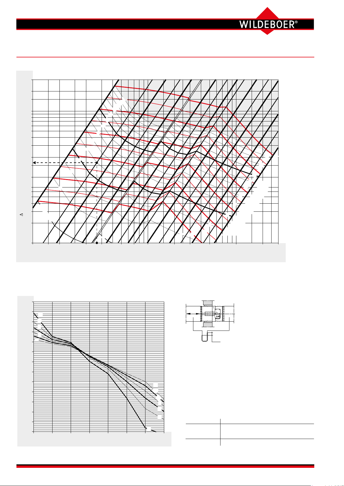
Sound power level
500
560
630
710
800
Pressure drop
Flow velocity va [m/s]
Relative sound power level ∆L [dB]
FR90 re dampers
Dimensioning (1) pressure drop, sound power level with ventilation duct connection on both sides
300
200
150
100
70
50
40
30
20
15
10
7
6
5
]aP[p
4
v = 2 m/s
A
S
3
2
1
Volume flow V [m³/h]
Nominal size DN [mm]
6
5
4
3
200 300 500 700 1000 2000 3000 5000 10000 20000100 3000050 75
140
100
15
14
13
12
11
10
9
8
7
2
125
160
3
20
180
200
25
224
4
250
5
30
280
6
40
7
315
8
355
10
9
50
400
15
14
13
12
11
60
WA
L [dB(A)]
450
70
FR90 re dampers can be used up to 15 m/s velocity in the inow cross-section AA and up to 2500 Pa operating pressure.
Relative sound power level
+25
+20
v
A
2
+15
4
+10
8
12
+5
5
0
0
-5
-10
-15
-20
-25
-30
-35
-40
63
Oktav-Mittenfrequenz [Hz]
125
Octave mid frequency [Hz]
250
v
A
12
10
8
6
4
2
500 1000 2000 4000 8000
LR
p
S
Example: Both sides with ventilation duct connection
V = 265 m³/h
DN = 125 mm
vA = 6 m/s
Dps = 16 Pa
LWA = 38 dB(A)
Sound power level L
f [Hz] 63 125 250 500 1000 2000 4000 8000
LWA [dB(A)] 38 38 38 38 38 38 38 38
DL
L
[dB] +12 +6 +4 -2 -7 -15 -23 -30
6 m/s
[dB] 50 44 42 36 31 23 - -
W-Oct
for the octave mid frequencies
W-Oct
Nomenclature
⇒
see page 11
User Manual 5.3 (2018-07) 10 Subject to change
Series FR92

FR90 re dampers
Dimensioning (2) Free cross-sections, weights, nomenclature
Free cross-sections A
DN A
free
[m²] RE100 RE150
[m²], weights [kg]
free
Fire
damper
Installation subframe
Mounting
frame
Installation
subframe
Mounting
frame
[m²] FR90 FR90 RH100 RH150 RR100 RR150 AE ER6 RV
100 0.0047 2.3 2.0 3.0 1.4 2.2 3.5 4.9 2.1
125 0.0082 2.5 2.4 3.6 1.7 2.5 4.1 5.7 2.5
140 0.0108 2.6 2.6 3.9 1.8 2.7 4.5 6.1 2.7
160 0.0149 2.7 3.0 4.5 2.0 3.0 5.0 6.8 3.1
180 0.0195 2.9 3.3 5.0 2.2 3.3 5.5 7.4 3.4
200 0.0248 3.1 3.7 5.5 2.4 3.6 6.1 8.1 3.8
224 0.0298 3.6 4.1 6.2 2.7 4.0 6.8 8.2 4.2
250 0.0383 3.9 4.7 7.0 2.9 4.4 7.6 9.0 4.8
280 0.0494 4.3 5.3 7.9 3.2 4.8 8.5 9.9 5.4
315 0.0642 4.9 6.0 9.0 3.6 5.3 9.6 11.0 6.1
355 0.0806 7.9 7.6 11.4 - - 11.8 14.3 7.0
400 0.1051 9.0 8.7 13.1 - - 13.4 16.2 8.1
450 0.1356 10.4 10.0 15.1 - - 15.3 18.5 9.4
500 0.1702 11.8 11.5 17.2 - - 17.3 20.9 10.7
560 0.2169 13.7 13.3 19.9 - - 19.9 23.9 12.4
630 0.2786 16.1 15.5 23.2 - - 23.0 27.7 14.6
710 0.3584 19.1 18.2 27.3 - - 26.8 32.3 17.2
800 0.4603 22.8 21.5 32.3 - - 31.3 37.9 20.3
The weight of the re dampers must factor in the weight of the
• installation subframes RE, RH, RR, ER6, the mounting frame AE or the mounting frame RV;
• The following must be added for actuators:
- M220-10/F; M24-10/F: 1.5 kg
- M220-9/H; M24-9/H: 2 kg
- M220-11/H; M24-11/H: 2 kg
- EM-1, RM-1; EM-2: 5 kg
Nomenclature
DN [mm] Nominal size
AA [m²] Inow cross-section
A
[m²] Free cross-section
free
V [m³/h] Volume ow
vA [m/s] Flow velocity in inow cross-section (inow velocity)
Dps [Pa] Static pressure drop
L
[dB] Octave sound power level L
W-Oct
DL [dB] Relative sound power level to L
W-Oct
= L
WA
WA
+ DL
f [Hz] Octave mid frequency
LWA [dB(A)] A-weighted, area-corrected sound power level
Series FR92
User Manual 5.3 (2018-07) 11Subject to change
s 15≥
s 15≥
s 15≥
CLOSED
release mechanism
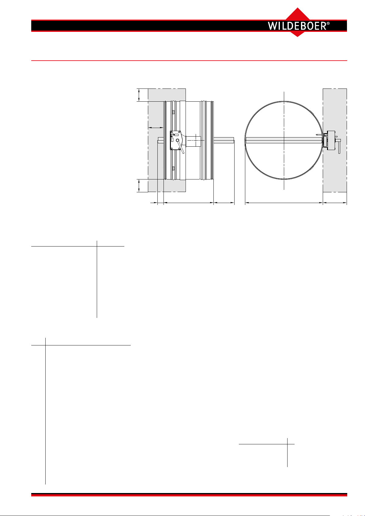
FR90 re dampers
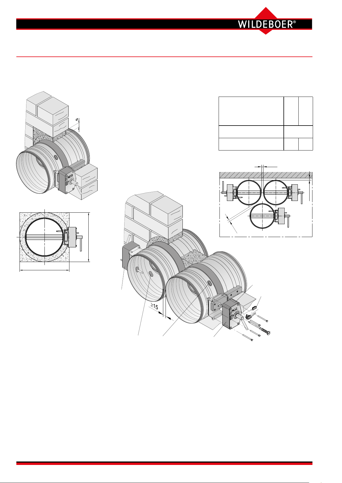
Installation in rigid walls and ceilings (1)
Installation without installation
subframe (standard installation)
The rigid walls and ceilings can
be made of concrete, lightweight
concrete, porous concrete (aerated
concrete) or plaster. They can be a
masonry or wallboard construction
and must have a bulk density of
≥ 450 kg/m³. Walls can also be re
walls, shaft walls, shafts or ducts.
The all-round ≥ 15 mm wide gap "s"
should be lled ≥
100 mm deep
with
mortar of group II or III according to
DIN 1053 or classes M2.5, M5, M10
or M20 according to EN 998-2, or
with the corresponding re-protection
mortar or gypsum mortar.
To install the FR90 re dampers in
rigid walls and ceilings, the mini-
mum thicknesses W, D [mm] are
required:
Fire resistance period
in minutes
Rigid walls 95
Rigid ceilings
100 115
30
60
90
30
60
90
120
d or. a
b
Installation opening a x b or ∅ d
a ≥ DN + 30 mm, b ≥ DN + 75 mm,
d ≥ DN + 75 mm
Clearance between FR90 re
dampers≥ 15 mm.
Installation does not require a
specic opening when the wall or
ceiling is built.
Actuator
on the left
Control openings
(inspection openings)
Installation with mortar
in walls and ceilings with
only 15 mm spacing.
Operation
unit on right
Blind cap
E-
Thermal-mechanical
User Manual 5.3 (2018-07) 12 Subject to change
Series FR92

RE 100 / 150
Installation
FR90 connection
brackets for attachment
Installation
alternative
FR90 connection
brackets for attachment
Installation
subframe
RR
100 / 150
FR90 connection
brackets for attachment
Screw M6x20
Installation
subframe
100 / 150
Fill on both sides
FR90 connection
brackets for attachment
FR90 re dampers
Installation in rigid walls and ceilings (2)
Installation with rectangular
installation subframes RE100, RE150
Screw M6x20
subframe
RE
100 / 150
Installation with mortar
Screw M6x20
subframe
RE
100 / 150
alternative
Installation with
mineral wool
Fill on
both sides
alternative
Screw
M6x20
Installation
subframe
Installation with circular installation sub-
frames RR100, RR150 (only DN ≤ 315 mm)
Screw M6x20
Installation
subframe
RR
100 / 150
RR
Screw
M6x20
For installation in rigid walls and
ceilings, the minimum thicknesses
W, D [mm] are required:
Fire resistance period
in minutes
30
60
30
60
90
Rigid walls 70*)100
Rigid ceilings
*) This installation must be performed with
installation subframe RE100 or RR100.
b
- 100
a
b
Installation openings
• Installation with mortar
DN ≤ 315: a x b = DN + 120 to 190
DN ≥ 355: a x b = DN + 130 to 200
DN ≤ 315: ∅ d = DN + 130 to 170
DN ≤ 200: a x b = DN + 130
Fill gap s with mortar! ⇒ see page 12
Mortaring in ceilings must be secured
from falling out by roughening the
reveals or using mortar anchors!
• Installation with mineral wool
DN ≤ 315: a x b = DN + 110 to 130
DN ≥ 355: a x b = DN + 120 to 140
DN ≤ 315: ∅ d = DN + 120 to 140
Design gap s ≤ 20 mm and ll with
mineral wool! ⇒ see page 14
Mineral wool must be prevented from
falling out by using a non-combustible
adhesive! A sheet metal cover is rec-
ommended when using mineral wool!
• Filled installation
DN ≤ 315: a x b = DN + 93 mm
DN ≥ 355: a x b = DN + 103 mm
DN ≤ 315: ∅ d = DN + 103 mm
Joints must be designed approx. 2 mm
and sealed on both sides of the wall
or ceiling with gypsum ller or with
non-combustible adhesive!
Adhesive ⇒ see page 44
d bzw. a
Filled installation
Series FR92
All dimensions in mm
User Manual 5.3 (2018-07) 13Subject to change
Settlement joint
s 15≥
Rigid ceiling
B
Settlement joint
s 15≥
C
Rigid ceiling
FR90 connection
bracket
RE
Release
mechanism
or actuator
W, D
09≥
54≥
s
s
s
A
A X
s
s
c
A-A
Y
Installation
subframe RE
ND x 9.0≤
0.9 x DN≤
A-A
Settlement joint possible
A
C-C
Lintel
Mortar
Settlement joint
B-B
Mortar
Reinforcement
Metal dowel
corner bracket
Wall / ceiling
s
FR90 connection bracket
Metal anchor M6
Screw M6
Wall
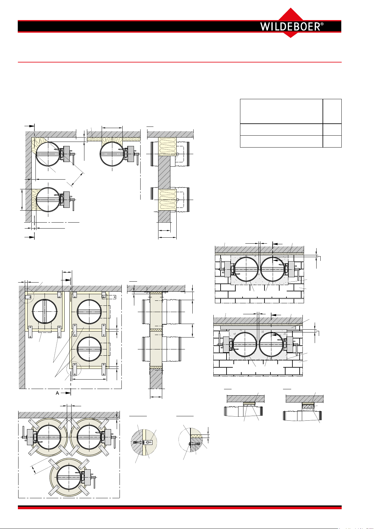
FR90 re dampers
Installation in rigid walls and ceilings (3)
In hard-to access corners and directly on walls and ceilings, gaps "s" on
FR90 re dampers without installation subframe can be lled with two layers
and 150 mm deep with mineral wool
"Knauf
Insulation
TPD"
or equivalent.
They must be secured with non-combustible adhesive. A sheet metal cover
is recommended when using insulation wool. IMortaring in ceilings must be
prevented from falling out by roughening the reveals or using mortar anchors!
05s51
≤≤
15 s 50≤ ≤
15 s 50≤ ≤
A
Multiple installation of up to 4 x FR90 re dampers of the same size
side-by-side, above each other or in a combined manner is possible
without any weight restriction. Assembly of frames RE
0.9 x DN≤
Partial mortaring
Mineral wool:
Bulk density ≥ 150 kg/m³
Melting point ≥ 1000°C
Adhesive ⇒ see page 44
W, D
150
⇒ see page 21
Settlement joints (sliding ceiling connection)
above non-load-bearing rigid walls and under ceilings are lled on site, with mineral wool for example. The illustration shows the installation of FR90
re dampers immediately under such settlement
joints. A reinforcement should be inserted into the
mortar bed or a lintel to prevent cracks from forming later.
For installation in rigid walls and
ceilings, the minimum thicknesses
W, D [mm] are required:
Fire resistance period
in minutes
30
60
90
Rigid walls 100
Rigid ceilings
Types of walls and ceilings
⇒ see page 12
B
FR90 fire dampers
100
Overlap
15 mm≥
Installation opening
Non-load-bearing
rigid wall
≥ 100 mm thick
C
FR90 fire dampers
Settlement joint
User Manual 5.3 (2018-07) 14 Subject to change
c
c
Detail X
s
FR90
Screw M6
M6
Detail Y
Spacings c between subframes RE or RR that are not directly next to each other depend
on the structural properties of the wall or ceiling. C ≥ 50 mm is normally sucient. For
installation in walls, 4 x FR90 connection brackets or FR90 corner brackets are
required on one side; for installation in ceilings, they are necessary on both sides (8 x).
Series FR92
Lintel
Overlap
15 mm≥
Installation opening
Non-load-bearing
rigid wall
≥ 100 mm thick

A-A
Pass-through
FR90 re dampers
Mounting on rigid walls and ceilings
Mounting with mounting frame AE
Types of walls and ceilings ⇒ see page 12
Mounting
frame
AE
Mounting on masonry (example)
Mounting frames AE should be
secured with threaded rods which
pass through the wall or ceiling,
and washers and nuts on both
sides.
Dowels with verication of re protection suitability can be used in
suitable walls and ceilings.
Factory-produced holes in the
mounting frames AE indicate the
number of the fastenings.
DN pc pc
[mm] per corner in total
To mount the FR90 re
dampers, the opposite
Minimum thickness
Fire resistance period
in minutes
30
60
90
W, D [mm] is required:
Rigid walls and ceilings 100
128
threaded bolt M6
or dowel
Ventilation duct
as required
W, D
160W, D ≥
s
Mounting frame AE
A
A
FR90
DN 100 125 140 160 180 200 224 250 280 315 355 400 450 500 560 630 710 800
AE 210 235 250 270 290 310 334 360 390 425 475 520 570 620 680 750 830 920
x1 - - - - - - - - - - 228 250 275 300 330 365 405 450
x2 120 145 160 180 200 220 244 270 300 335 385 430 480 530 590 660 740 830
A
A-A
d
x1
x2
AE
AE washerHexagon nut M6
1x
2x
EA
≤ 315 1 4
≥ 355 2 8
d
Installation opening
∅d = DN + 10 to 15 mm
The gap between ventilation duct
and wall or ceiling does not need
to be lled.
55≥
011≥
AEAE
Release mechanism
or actuator
A
EA
EA≥
EA
W, D
Spacing between the mounting frames AE of the FR90 re dampers and from
the adjacent walls and ceilings is not required.
Ventilation ducts on the non-operation side of the FR90 re damper can
be fed through the wall or ceiling and should lie ush. The connection of the
FR90 re damper on the non-operation side can be fully inserted in these.
Connections can be made to the casing of missing re dampers if it is
ensured that the damper blade can move freely! ⇒ see page 9
All dimensions in mm
Series FR92
User Manual 5.3 (2018-07) 15Subject to change
 Loading...