

Page 1

W
ILDCAT
Scale
Technical Manual
E15609900A
12/00.01
Page 2

© Mettler-Toledo, Inc. 2000
No part of this manual may be reproduced or transmitted in any form or by any means, electronic or
mechanical, including photocopying and recording, for any purpose without the express written permission
of Mettler-Toledo, Inc.
U.S. Government Restricted Rights: This documentation is furnished with Restricted Rights.
Page 3
CUSTOMER FEEDBACK
Your feedback is important to us! If you have a problem with this product, or just a suggestion on how we can serve you better,
please fill out this form and send it to us. If you are in the United States, you can mail this postpaid form to the address on the
reverse, or fax it to (614) 438-4355. If you are outside the United States, please apply the appropriate amount of postage before
mailing. You can also send your feedback via email to: [email protected]
Your Name: Date:
Organization Name: METTLER TOLEDO Order Number
Address: Part / Product Name:
Part / Model Number:
Serial Number:
Phone Number: ( ) Fax Number: ( ) Company Name for Installation:
E-mail Address: Contact Name:
Phone Number:
How well did this product meet your
Comments:
expectations in its intended use?
Met and exceeded my needs
Met all needs
Met most needs
Met some needs
Did not meet my needs
COMMENTS/QUESTIONS:
DO NOT WRITE IN SPACE BELOW; FOR METTLER TOLEDO USE ONLY
Retail Light Industrial Heavy Industrial Systems
RESPONSE: Include Root Cause Analysis and Corrective Action Taken.
.
Page 4
E
FOLD THIS FLAP FIRST
NO POSTAGE
NECESSARY IF
MAILED IN THE
UNITED STATES
BUSINESS REPLY MAIL
FIRST CLASS PERMIT NO. 414 COLUMBUS, OH
POSTAGE WILL BE PAID BY ADDRESSE
Mettler-Toledo, Inc.
Quality Manager - MTWI
1150 Dearborn Drive
Worthington, Ohio 43085
USA
Please seal with tape.
Page 5

INTRODUCTION
Information regarding METTLER TOLEDO Technical Training may be obtained by contacting:
METTLER TOLEDO
1900 Polaris Parkway
Columbus, Ohio 43240
(US and Canada) 614- 438-4511
(All Others) 614-438-4888
FCC Notice
This device complies with Part 15 of the FCC Rules and the Radio Interference Requirements of the
Canadian Department of Communications. Operation is subject to the following conditions: (1) this device
may not cause harmful interference, and (2) this device must accept any interference received, including
interference that may cause undesired operation.
This equipment has been tested and found to comply with the limits for a Class A digital device, pursuant
to Part 15 of FCC Rules. These limits are designed to provide reasonable protection against harmful
interference when the equipment is operated in a commercial environment. This equipment generates,
uses, and can radiate radio frequency energy and, if not installed and used in accordance with the
instruction manual, may cause harmful interference to radio communications. Operation of this equipment
in a residential area is likely to cause harmful interference in which case the user will be required to correct
the interference at his or her own expense.
This manual correctly describes the operation and functionality of the WILDCAT scale containing software
version 125362 Sr 2.00. The software version is displayed during the power-up sequence.
METTLER TOLEDO RESERVES THE RIGHT TO MAKE REFINEMENTS OR
CHANGES WITHOUT NOTICE.
Page 6
PRECAUTIONS
SAFETY NOTICE
Product safety is a fundamental concern at METTLER TOLEDO. Use common sense and follow the simple
precautions listed below to ensure your safety and optimize the use and performance of this product.
• Read this manual before operating or servicing this product. Save this manual for future reference.
• Observe safety warnings located throughout this manual.
• Use caution when lifting or moving heavy equipment.
• Engage wheel brakes before operating WW (mobile / wheeled) products.
• Do not use this product in washdown environments. Never immerse electronic products in liquids.
• This product should be serviced by qualified personnel. Exercise care when moving, testing, or adjusting this product.
• Disconnect all power to this product before installing, servicing, or cleaning.
• Use only METTLER TOLEDO parts for repair.
• Observe electrostatic handling precautions for electronic components. Allow at least 30 seconds after power disconnection to
allow charges to dissipate before servicing any electronic components.
• Allow the product to stabilize at ambient room temperature before applying power.
FAILURE TO FOLLOW THESE PRECAUTIONS COULD RESULT IN DAMAGE TO EQUIPMENT OR
BODILY HARM.
Page 7

CONTENTS
1 Introduction...................................................................................................1-1
Specifications..................................................................................................................... 1-1
2 Assembly Procedures..................................................................................... 2-1
Assembly Instructions......................................................................................................... 2-1
Load Cell Wiring................................................................................................................. 2-3
Serial Port Connections ...................................................................................................... 2-3
3 Programming and Calibration......................................................................... 3-1
Key Functions..................................................................................................................... 3-2
Entering the Programming Mode ......................................................................................... 3-2
Entering and Configuring Program Blocks............................................................................. 3-3
Exiting the Programming Mode ........................................................................................... 3-3
Sealing the Enclosure (Legal for Trade) ............................................................................... 3-3
Factory Default Settings ...................................................................................................... 3-4
F1 Scale Block.................................................................................................................... 3-5
F2 Application Block ........................................................................................................... 3-7
F3 Interface Block............................................................................................................... 3-8
Exit Sub-Block.................................................................................................................... 3-9
Calibration....................................................................................................................... 3-10
Gravity Adjustment ........................................................................................................... 3-10
4 Maintenance and Troubleshooting................................................................... 4-1
Cleaning ............................................................................................................................ 4-1
Troubleshooting.................................................................................................................. 4-1
Error Codes........................................................................................................................ 4-1
Voltage Checks................................................................................................................... 4-2
AC Power Test ......................................................................................................... 4-2
Controller PCB Input Voltage Test................................................................................ 4-2
Check Battery Voltage(Battery-powered units)........................................................... 4-2
RS232 Serial Output Test .......................................................................................... 4-2
Parts Replacement and Adjustments .................................................................................... 4-3
Battery Replacement ............................................................................................................ 4-3
Keyboard Replacement......................................................................................................... 4-4
Controller PCB Replacement.................................................................................................. 4-4
Load Cell Replacement......................................................................................................... 4-5
Overload Stop Adjustment..................................................................................................... 4-6
Shift Test ............................................................................................................................ 4-7
Power-Up Sequence............................................................................................................ 4-8
Page 8

5 Parts List ...................................................................................................... 5-1
Column and Base (WS30, WS60, WS150)........................................................................... 5-2
Column and Base (WW250 and WW500) ............................................................................ 5-3
6 Appendices ................................................................................................... 6-1
Appendix 1: Demand Mode Output....................................................................................... 6-1
Weight Field Format.............................................................................................................6-1
Appendix 2: Continuous Mode Output .................................................................................. 6-4
Status Byte Definition............................................................................................................ 6-5
Appendix 3: ASCII Input Commands .................................................................................... 6-6
Appendix 4: GEO Codes ...................................................................................................... 6-7
Page 9
1 Introduction
The WILDCAT bench and portable scale is designed to meet the real world requirements
of manufacturing, agricultural, packaging, and general weighing applications, and is
ready to use right out of the box. This manual provides important information for
installing and servicing the scale. For information on operating the scale, refer to the
Operator’s Card provided with the unit.
The WILDCAT scale is intended for use in general purpose industrial and commercial
environments. For the best performance, it should not be used in environments requiring
washdown, immersion in liquids, or exposure to corrosive chemicals.
Specifications
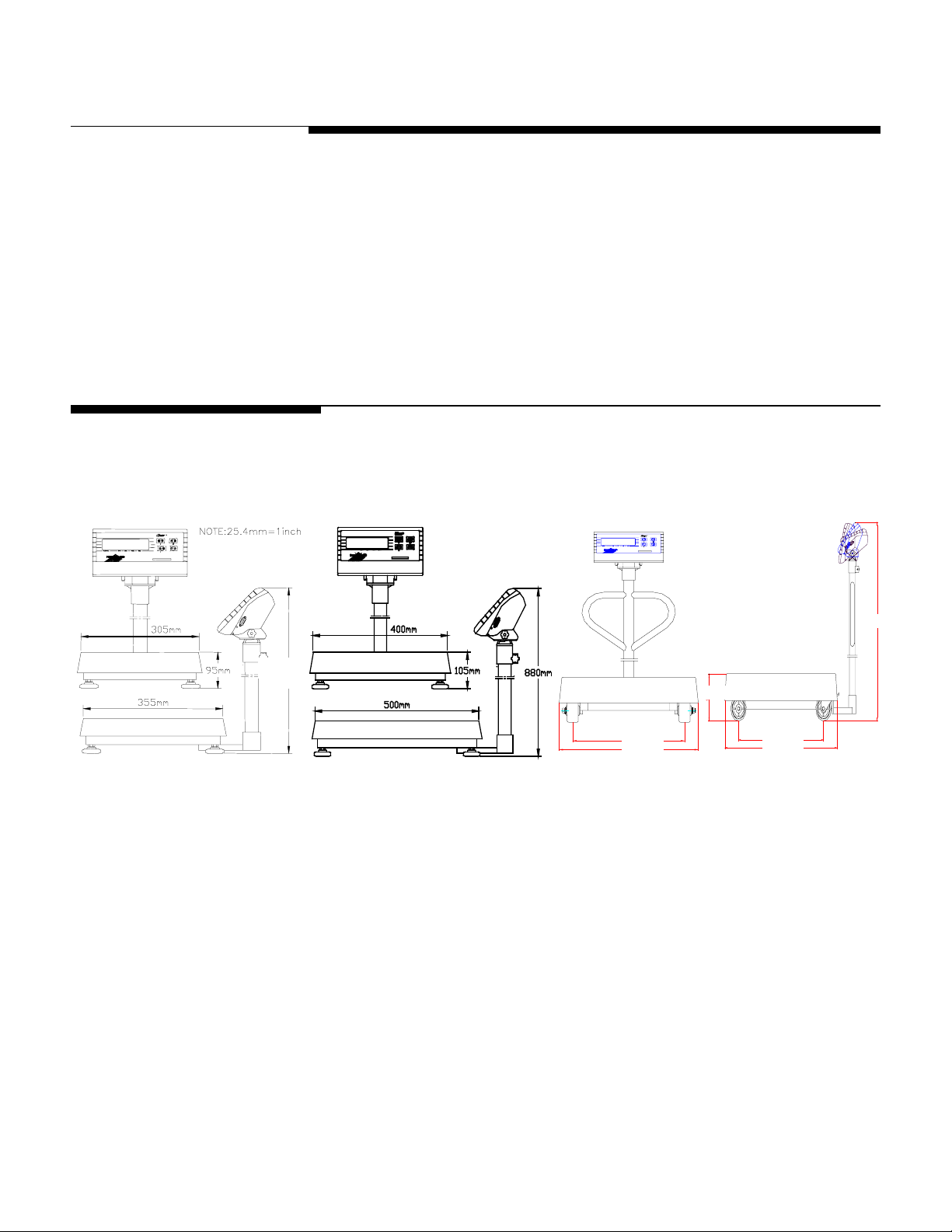
The WILDCAT scale is available in three base sizes. Specifications for the models below
are listed on the next page.
Chapter 1: Introduction
Specifications
540 mm
540 mm
Figure 1-1: WS30R, WS60R Figure 1-2: WS60LR, WS150R
190 mm
418 mm
520 mm
544 mm
720 mm
Figure 1-3: WW250, WW500
1250 mm
(12/00) 1-1
Page 10
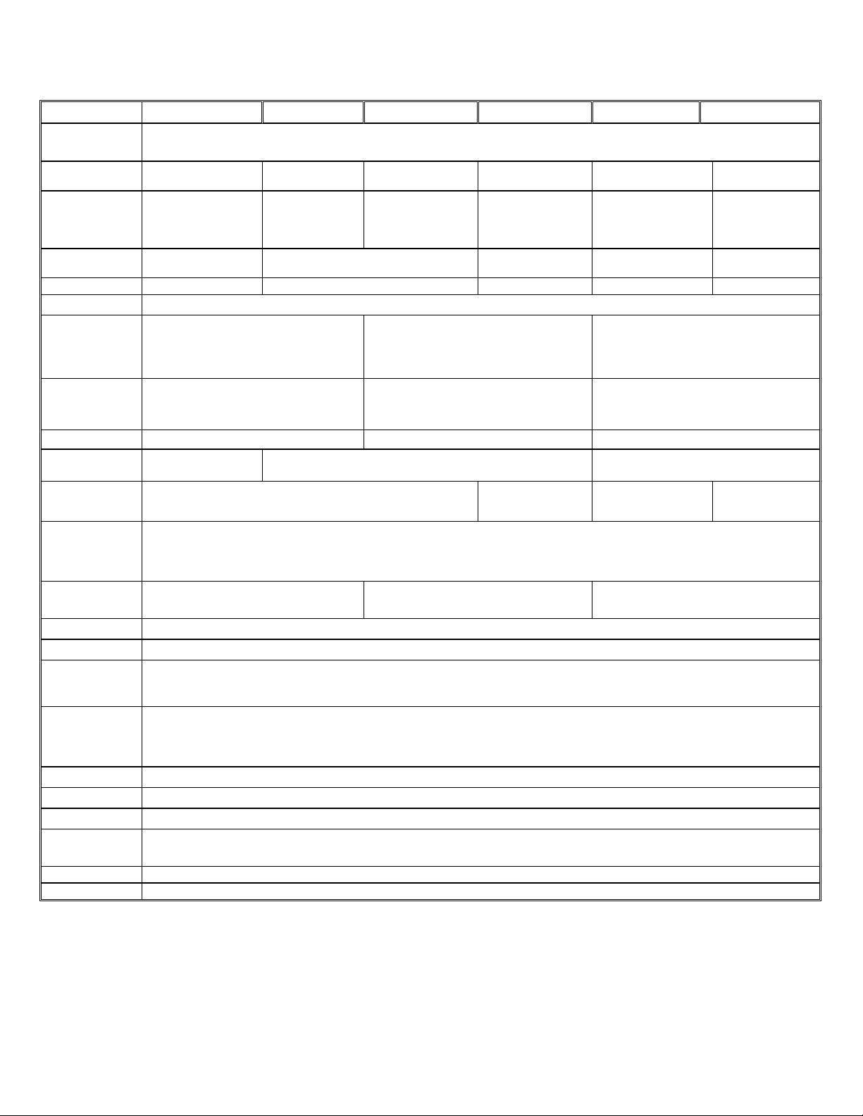
METTLER TOLEDO WILDCAT Scale Technical Manual
WS30R/WS30VR WS60R/WS60VR WS60LR/WS60LVR WS150R/WS150VR WW250VR WW500VR
Displayed
Resolution
Maximum Capacity
Minimum Division
Size
Trade -Approved
Build
Maximum Back
weight
Safe Overload 45 kg (90 lb) 90 kg (225 lb) 225 kg (450 lb) 300 kg (660 lb) 600 kg (1320 lb)
Corner Loading
Base Dimensions
W x D x H
Scale Dimensions
W x D x H
Actual Weight 11 kg (24 lb) 22 kg (49 lb) 50 kg (110 lb)
Shipping Weight
Load Cell (2mV/V) 100 kg (220 lb) 250 kg (550 lb) 500 kg 1000 kg
30 kg (60 lb)
0.01 kg
(0.02 lb)
30 kg (60 lb) 10 kg (4 lb) 30 kg (95 lb)
305 x 355 x
(95 – 110)** mm
12 x 14 x
(3.8 – 4.3**) in
305 x 500 x (540 – 555)** mm 400 x 650 x (885 – 990)** mm 510 x 850 x 1320 mm
12 x 19.7 x (21.3 – 21.8)** in 15.7 x 25.6 x (34.8 – 35.3)** in 20 x 33.5 x 52 in
14 kg (31 lb)
60 kg (150 lb)
0.01kg
(0.05 lb)
60 kg (150 lb)
0.02 kg
(0.05 lb)
400 x 500 x (105 – 120)** mm 510 x 710 x 200 mm
30 kg (66 lb)
Up to 10,000d
100% of full capacity.
15.7 x 19.7 x (4.1 – 4.6)** in 20 x 28 x 7.8 in
150 kg (300 lb)
0.05 kg
(0.1 lb)
250 kg (500 lb)
0.1 kg
(0.2 lb)
90 kg (200 lb) 180kg (400 lb)
51 kg (112 lb)
500 kg (1000 lb)
0.2 kg
(0.5 lb)
Construction
Column
Construction
Environment General purpose, dry. Load cell is moisture- and dust-resistant.
Display Six-digit, 25 mm (1 in) tall, high contrast, LCD
Keypad 4 color-coded, tactile-feel keys
Approvals UL Listed
Power 10.2 VDC / 0.15 A (AC transformer included) or six “D” cells
Battery Life Up to 500 hrs with six ‘D Cell’ batteries
Operating Temp.
Storage
Temperature
Data Output ASCII via RS-232 standard
Weighing Units pounds, kilograms and grams
*NTEP and Industry Canada approvals pending on WW models
** The height will vary depending on the height of the leveling feet.
***Information not available at this time.
350 mm (14 in) stainless steel 700 mm (28 in) stainless steel 1118 mm (44 in) stainless steel
Platter: Fabricated 304 Stainless Steel
Base Support Frame: Formed and Welded Carbon Steel Polyurethane Painted Navy Blue
Display Enclosure: ABS Charcoal Gray Plastic
ZERO, TARE, FUNCTION, and PRINT
Industry Canada AM-5319*
NTEP Class III #99-053*
-10°C to 40°C with 10 to 95% relative humidity, non-condensing
-20°C to 60°C with 10 to 95% relative humidity, non-condensing
Table 1-1
(12/00) 1-2
Page 11
“”
Enchufa o utilice seis
baterías tipo “”D
Herramientas adicionales
que pudiese necesitar
Additional tools
you may need
Plug in or use
6 “D ” size batteries
2 Assembly Procedures
Assembly Instructions
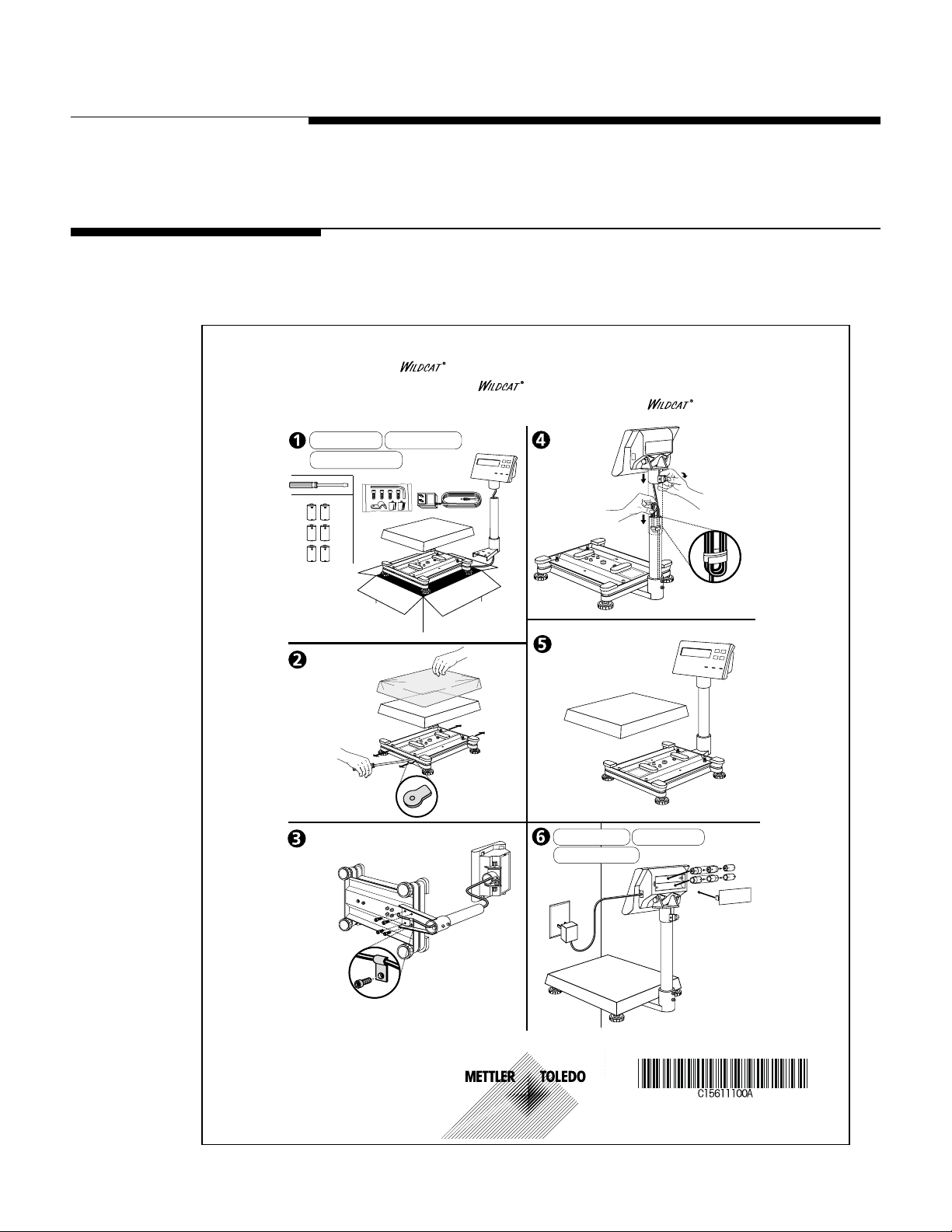
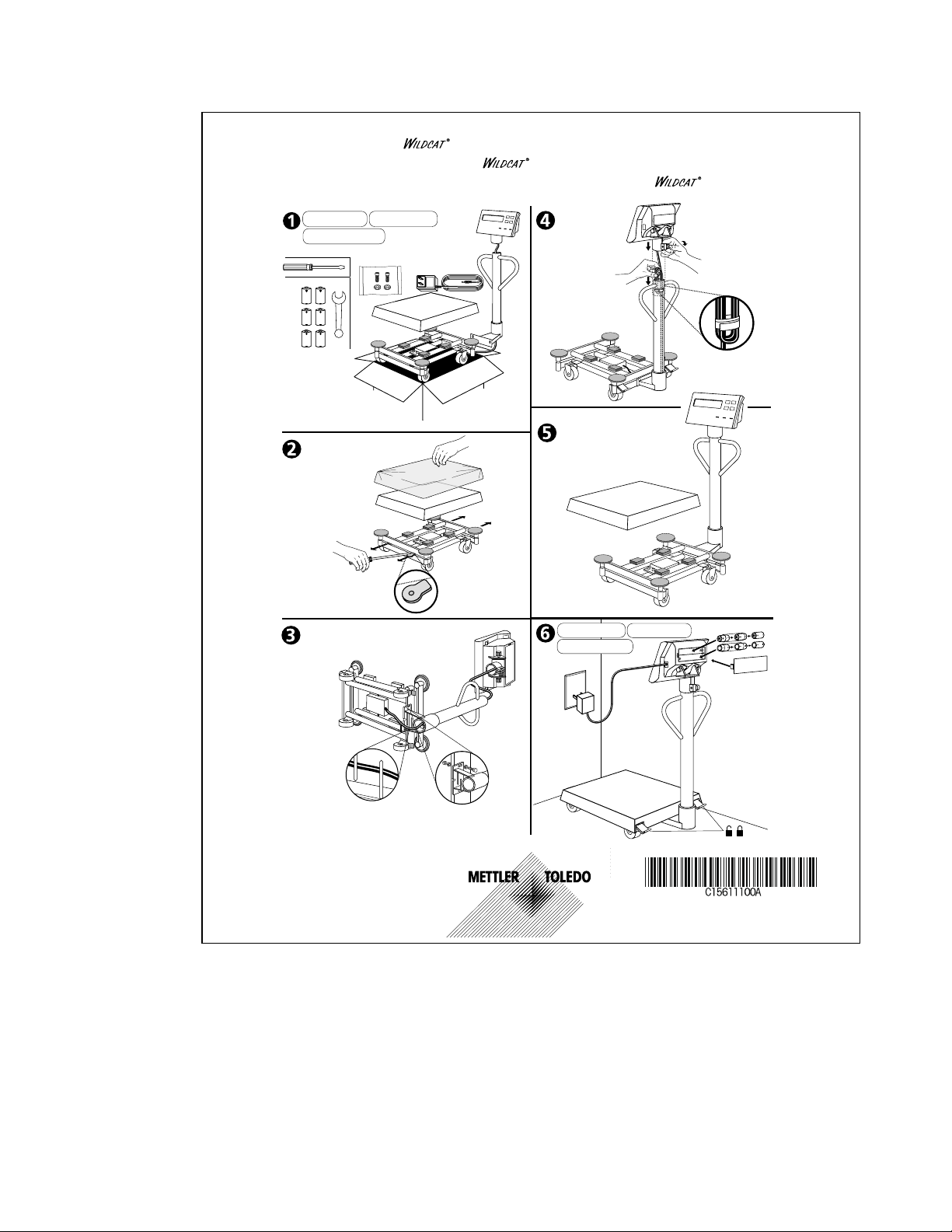
Assembly instructions for the WILDCAT scale are provided with the unit. A copy of these
instructions appears below and on the next page.
Báscula Portátil de Mesa Instrucciones Para Ensamblaje
Instructions D‘assemblage de la Bascule
Outils supplémentaires dont
vous pourriez avoir besoin
Wi
Scale Assembly Instructions
Chapter 2: Assembly Procedures
Assembly Instructions
Branchez le courant ou
utilisez 6 piles de taille D
© 2000 Mettler-Toledo, Inc.
Figure 2-1: Assembly instructions for Models WS30, WS60, and WS150
(12/00) 2-1
Page 12
METTLER TOLEDO WILDCAT Scale Technical Manual
Outils supplémentaires dont
vous pourriez avoir besoin
Branchez le courant ou
utilisez 6 piles de taille D
“”
Enchufa o utilice seis
baterías tipo
“”D
Herramientas adicionales
que pudiese necesitar
Additional tools
you may need
Plug in or use
6 “D ” size batteries
Báscula Portátil de Mesa Instrucciones Para Ensamblaje
Instructions D‘assemblage de la Bascule
Scale Assembly Instructions
© 2000 Mettler-Toledo, Inc.
Figure 2-2: Assembly instructions for Models WW250 and WW500
(12/00) 2-2
Page 13
Load Cell Wiring
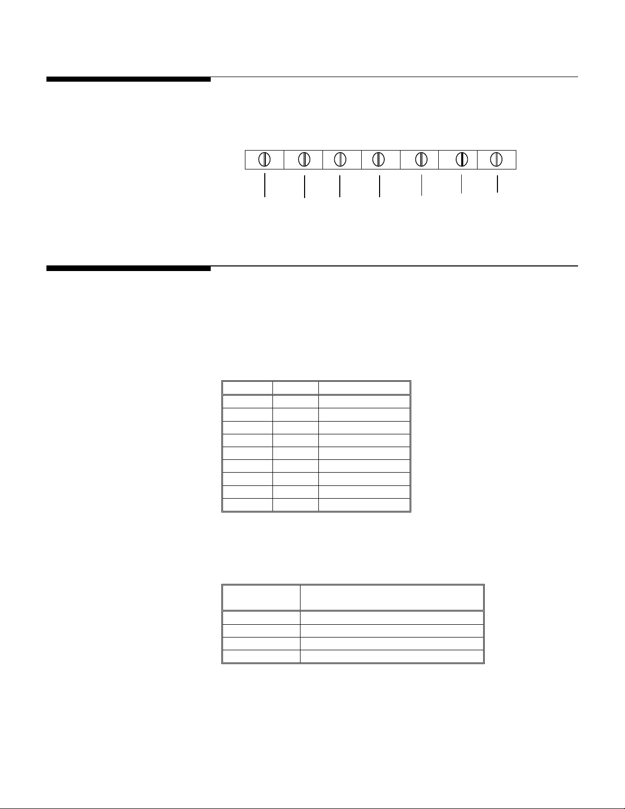
Figure 2-3 shows the load cell terminal strip wiring for the WILDCAT scale.
Serial Port Connections
The WILDCAT scale provides a bi-directional RS-232 port to be used to send data to or
receive commands from a computer, printer, or other serial device. The following chart
(Table 2-1) describes the pin configuration of the 9-pin D-Sub female connector on the
side of the terminal (indicator) of the WILDCAT scale. The maximum recommended
cable length for RS-232 is 50 feet (15 meters).
NOTE: Bi-directional capability
was added in version 2.0
software. Previous versions did
not provide ASCII input
commands.
Table 2-2 shows the ASCII commands that may be used to communicate with the
WILDCAT scale via the serial port. A more complete explanation is given in Appendix 3.
Chapter 2: Assembly Procedures
+EXC +SEN +SIG Shield -SIG -SEN -EXC
Green Blue Red Orange White Brown Black
Figure 2-3
Pin Signal Description
1 Not Connected
2 RxD Receive Data
3 TxD Transmit Data
4 Not Connected
5 Gnd Logic Ground
6 Not Connected
7 Not Connected
8 Not Connected
9 Not Connected
Table 2-1
ASCII
Function Performed in the WILDCAT Scale
Command
C Clear Tare
T Tare
P Print
Z Zero
Table 2-2
Load Cell Wiring
(12/00) 2-3
Page 14

METTLER TOLEDO WILDCAT Scale Technical Manual
NOTES
(12/00) 2-4
Page 15
Chapter 3: Programming and Calibration
3 Programming and Calibration
WARNING
ONLY PERMIT QUALIFIED PERSONNEL TO SERVICE THIS EQUIPMENT.
EXERCISE CARE WHEN MAKING CHECKS, TESTS AND ADJUSTMENTS
THAT MUST BE MADE WITH POWER ON. FAILING TO OBSERVE THESE
PRECAUTIONS CAN RESULT IN BODILY HARM.
The WILDCAT scale is calibrated at the factory. Functional programming is also
completed at the factory, so that the WILDCAT scale is ready to use right out of the box.
There is no need to change any of the softswitch parameters or to calibrate the scale.
However, for commercial purposes (legal for trade), the WILDCAT scale must be
calibrated using certified test weights. All operational changes and calibration can be
performed using the scale keyboard.
Serial Port Connections
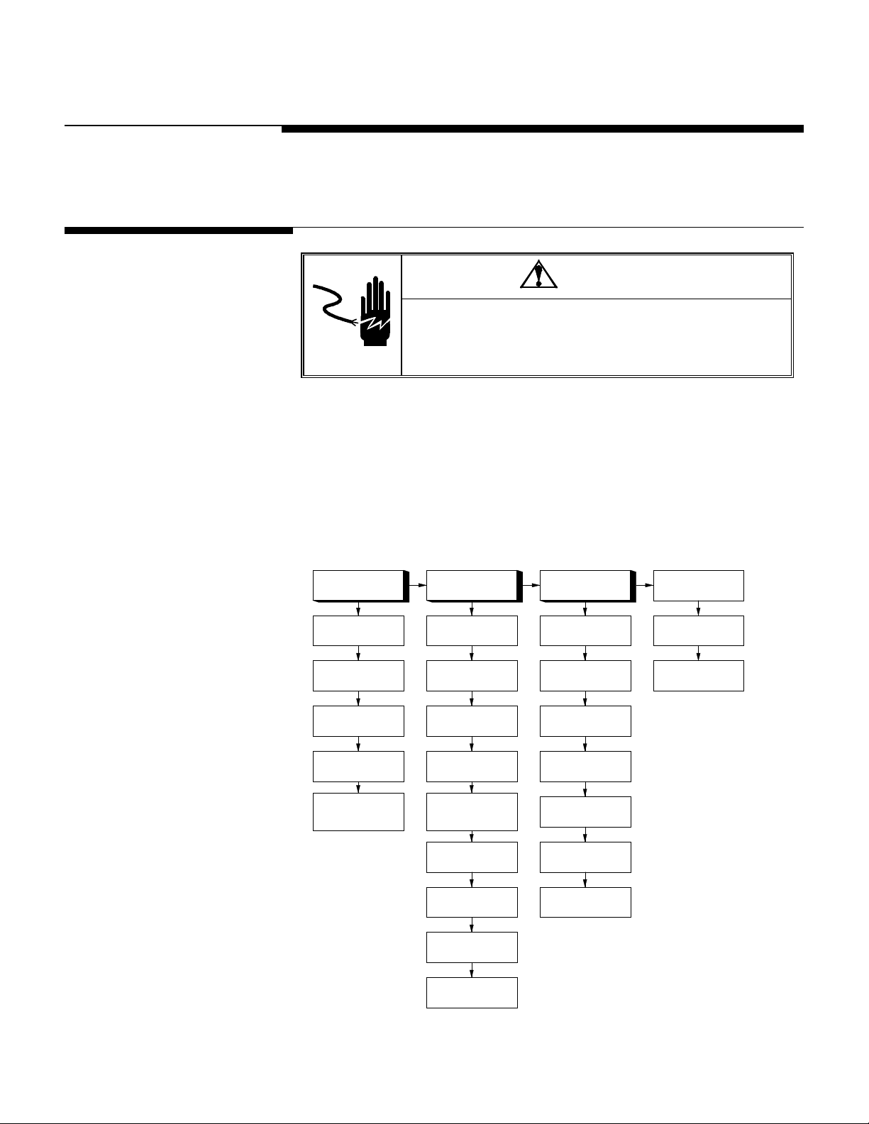
The programming mode of the WILDCAT scale consists of main blocks (F1, F2, and
F3), each containing sub-blocks (F1.1, F1.2, and so on.) An overview of the
programming mode is shown below.
F1 - Scale F2 - Application F3 - Serial I/F
F1.1
Calibration Units
GEO Code
F1.2
Calibration
F1.3
Display X10
F1.4
Programming Mode
Access
F2.1
Alternate Unit
F2.2
Auto Backlight
F2.3
Tare
F2.4
PB Zero Range
F2.5
Auto Zero
Maintenance
F2.6
Motion Sensitivity
F2.7
Filtering
Baud Rate
Data Format
Checksum
Gross Weight Legend
F3.1
F3.2
Data Bits
F3.3
Stop Bits
F3.4
Parity
F3.5
F3.6
F3.7
Save
Abort
Load Defaults
F2.8
Sleep Mode
F2.9
Power Up Zero Range
Figure 3-1
(12/00) 3-1
Page 16
METTLER TOLEDO WILDCAT Scale Technical Manual
Key Functions
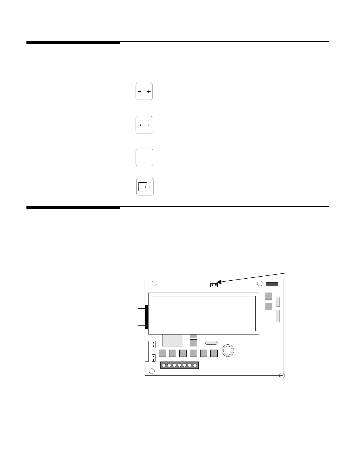
Should you need to reconfigure the WILDCAT scale, the following keys are used in the
programming mode to configure the program blocks.
0
T
ZERO Back up to the previous step.
TARE Moves the data entry position one digit to the left.
Entering the Programming
Mode
C
F
FUNCTION Increments the numeric data entry digit and/or allows the
programmer to view the next display in a selection list.
PRINT Accepts/terminates a data entry.
To access the program blocks, the CAL jumper must be in place shorting the two pins
on the Controller PCB. Refer to Figure 3-2 for the CAL position.
To configure the program blocks, you must enter the programming mode by pressing
and releasing the PRINT and ZERO keys simultaneously.
CAL
J-5
J-4
Figure 3-2
(12/00) 3-2
Page 17
Entering and Configuring
Program Blocks
Exiting the Programming
Mode
Chapter 3: Programming and Calibration
Entering and Configuring Program Blocks
Once the [F1] prompt is displayed, use the PRINT key to enter the block. Use the
FUNCTION key to skip to the next block. Use the ZERO key to go to the previous block.
Once PRINT is pressed, the configuration advances to the first parameter in the F1
program block. The display shows the sub-block number and the current value setting.
Press PRINT to accept the value and advance to the next sub-block or press the
FUNCTION key to toggle through the choices until the desired selection is displayed.
After the desired selection is displayed, press PRINT to accept the value. Continue this
procedure throughout the setup routine until all required changes have been made.
At the end of all the program blocks, there is a SAVE program block. In this block, you
can use the FUNCTION key to select SAVE, ABORT or DEFAULT. When the desired choice
is displayed, press PRINT. The scale exits the programming mode after the selection.
Sealing the Enclosure
(Legal for Trade)
SAVE The WILDCAT scale will save all the changes you have made to the program
blocks and then exit setup.
ABORT All changes will be discarded and the original programming will remain.
DEFAULT All blocks, except those steps denoted by *s in Table 3-1 are reset to the
factory defaults.
After calibration is complete, setup step F1.4 should be programmed as a “O” to
eliminate accidental changes to the calibration values. After programming is complete,
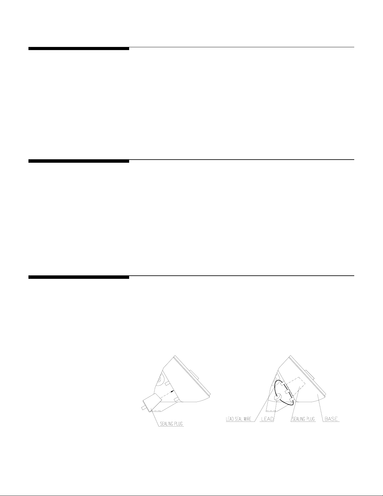
remove the setup jumper CAL (Figure 3-2) to prevent setup access. Close the enclosure,
tightening all four screws on the rear cover. Install the two plastic plugs over the bottom
screws and seal the enclosure as shown in Figure 3-3.
Figure 3-3
(12/00) 3-3
Page 18

METTLER TOLEDO WILDCAT Scale Technical Manual
Factory Default Settings
STEP DEFAULT DESCRIPTION
F1.1 *, ** Calibration units – No default
GEO * Gravity adjust – No default
F1.2 0 Skip calibration
F1.3 0 Normal weight display
F1.4 0** Programming mode access disabled
F2.1 0** Alternative units = none (Unit switch disabled)
F2.2 0** Auto Backlight disable
F2.3 1 Tare enable
F2.4 1** Push button zero enabled, 2% range
F2.5 1** Auto zero maintenance enabled
within 0.5d window
F2.6 1 Motion sensitivity +/- 1d
F2.7 0 No Filtering
F2.8 0 Sleep mode disable
F2.9 1** Auto zero capture at powerup range of +/- 2%
F3.1 9600 Serial output baud rate
F3.2 7 Data bits
F3.3 2 Stop bits
F3.4 2 Even parity
F3.5 2 Print format = single line gross-tare-net
F3.6 1 Checksum enable
F3.7 0 No printed legend for gross weight field
*These setup steps are not reset during a Reset to Factory Defaults.
**Initial factory settings for WILDCAT scales with country code 000.
Table 3-1
F1.1 = 1 F2.2 = 1 F2.5 = 2
F1.4 = 1 F2.4 = 2 F2.9 = 2
F2.1 = 2
(12/00) 3-4
Page 19
F1 Scale Block
Chapter 3: Programming and Calibration
F1 Scale Block
The scale program block allows the user to set and calibrate the features that affect
weighing performance.
[F1.1 2 ] CALIBRATION UNITS
Enter the value that corresponds to the type of test weights that will be
used for calibration.
1 = lb
2 = kg
3 = g
[ GEO 12 ] GRAVITY ADJUST
The WILDCAT scale is calibrated with a GEO code of 12 at the factory. To
adjust the factory calibration to your specific area, refer to Appendix 4 for
your GEO code. Enter the new GEO code and the calibration will
automatically be adjusted for your specific location.
[F1.2 0] SCALE CALIBRATION
0 = Skip Calibration and proceed to F1.3
1 = Enter into the Calibration Sub-block.
[CAP. ] SCALE CAPACITY
“CAP” displays momentarily then current scale capacity is shown. This
value is available for numeric entry editing. Press FUNCTION to clear the
data before entering new data.
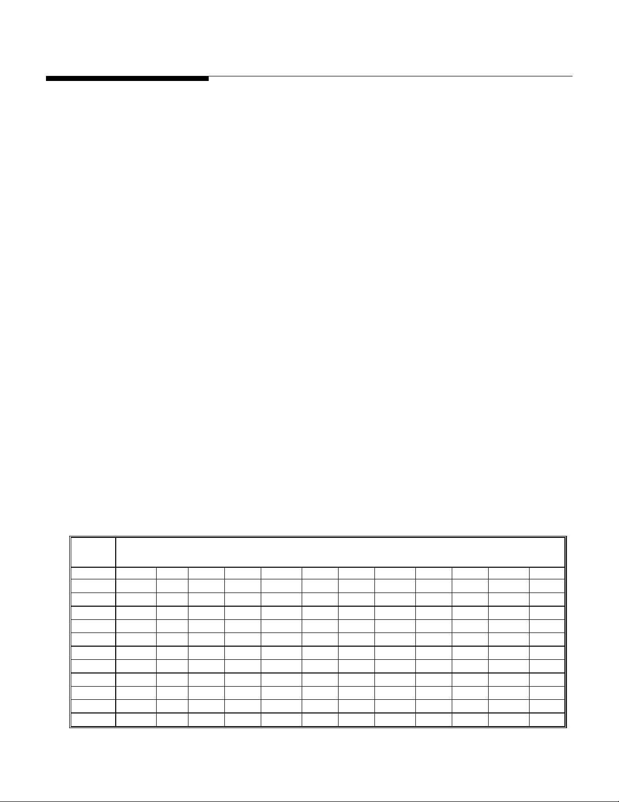
Table 3-2 shows all possible selections for capacity and increment.
Increment
Size
0.001 1 - - 2 - 3 4 5 6 - 8 10
0.002 2 - 3 4 5 6 8 10 12 15 16 20
0.005 5 6 - 10 - 15 20 25 30 - 40 50
0.01 10 12 15 20 25 30 40 50 60 - 80 100
0.02 20 24 30 40 50 60 80 100 120 150 160 200
0.05 50 60 - 100 - 150 200 250 300 - 400 500
0.1 100 120 150 200 250 300 400 500 600 - 800 1000
0.2 200 240 300 400 500 600 800 1000 1200 1500 1600 2000
0.5 500 600 - 1000 - 1500 2000 2500 3000 - 4000 5000
1 1000 1200 1500 2000 2500 3000 4000 5000 6000 - 8000 10000
2 2000 2400 3000 4000 5000 6000 8000 10000 12000 15000 16000 20000
5 5000 6000 - 10000 - 15000 20000 25000 30000 - 40000 50000
SCALE CAPACITIES (lb, kg or g)
Table 3-2
(12/00) 3-5
Page 20

METTLER TOLEDO WILDCAT Scale Technical Manual
[Incr. ] INCREMENT SIZE
[E SCAL] Empty scale platform and press PRINT to continue.
[15 CAL] Display countdown for zero setting. If motion sensitivity is not disabled
[Add Ld] Place test weight on the scale platform. Press PRINT.
[0000‘0’] Enter test weight value. No decimal point is permitted. Maximum test
“Incr” displays momentarily then the current increment size is displayed
for editing. Press the FUNCTION key to toggle through valid selections.
and motion is detected at this step, the display will show [ E 30].
Press PRINT and the display returns to the [E SCAL] prompt.
weight is 100% of full scale capacity. There is no minimum test weight
required but METTLER TOLEDO recommends using at least 50% of the
scale capacity.
[15 CAL] Display countdown for calibration. If motion is detected at this step then
the display will show [ E 30]. Press PRINT to return to the [Add Ld]
prompt.
[CAL d] "Calibration done" is displayed momentarily.
[F1.3 0 ] EXPANDED DISPLAY
0 = Normal display mode
1 = Weight displayed in minors
[F1.4 0] PROGRAMMING MODE ACCESS
If CAL jumper is installed on the Controller PCB, this step has no effect,
and the programming mode is always accessible.
If CAL jumper is not installed on the Controller PCB:
0 = No access to view or change values in the programming mode.
1 = Programming blocks F2 and F3 may be accessed to change the
parameters. Programming block F1 may only be viewed.
(12/00) 3-6
Page 21

F2 Application Block
Chapter 3: Programming and Calibration
F2 Application Block
[F2.1 0] ALTERNATE UNITS:
Select the unit of measure desired as a secondary unit.
0 = No unit switching
1 = lb
2 = kg
If the calibration unit is “kg ”, the available choice is only “lb”. If the
calibration unit is “lb” or ‘g’, the choice is only ‘kg”. If unit switching is
enabled, a quick press of the FUNCTION key will change the unit.
[F2.2 0 ] AUTO BACKLIGHT
0 = Backlight can only be turned on manually by pressing the
FUNCTION key.
1 = The backlight turns on during motion and stays on for 6 seconds
after no-motion.
The manual on/off is always available. If unit switching is enabled, press
and hold the FUNCTION key for 3 seconds to turn the back light on. If
unit switching is disabled, a quick press of the FUNCTION key will turn
the backlight on and off.
[F2.3 1] TARE
0 = Tare disabled
1 = Tare enabled
[F2.4 1] PUSHBUTTON ZERO RANGE
0 = Pushbutton zero disabled
1 = Enable pushbutton zero within +/- 2% of scale capacity
2 = Enable pushbutton zero within +/- 20% of scale capacity
[F2.5 1] AUTO ZERO MAINTENANCE
Auto Zero Maintenance (AZM) automatically compensates for small
changes in zero resulting from material build-up or temperature changes.
Select the weight range (+/-) around gross zero within which the scale
will capture zero. If residual weight on the scale exceeds the weight
range, the scale will not capture zero. AZM is disabled in the net mode.
0 = No AZM.
1 = AZM within 0.5d window.
2 = AZM within 1d window.
3 = AZM within 3d window.
(12/00) 3-7
Page 22

METTLER TOLEDO WILDCAT Scale Technical Manual
[F2.6 1] MOTION SENSITIVITY SELECTION
[F2.7 0] FILTER
The motion detection feature determines when a no-motion condition
exists on the scale platform. The sensitivity level determines what is
considered stable. Printing, pushbutton zero, and tare entry are blocked
during instability.
0 = Motion detector disabled
1 = 1.0 d motion sensitivity
2 = 3.0 d motion sensitivity
Filtering compensates for environmental disturbances such as vibration
or drafts.
0 = NONE
1 = LIGHT
2 = NORMAL
3 = HEAVY
F3 Interface Block
[F2.8 0] SLEEP MODE (power saving)
0 = Disable
1 = Enable the sleep mode automatically after 5 minutes of stability.
[F2.9 1] POWER UP ZERO RANGE
0 = Auto Zero capture at powerup disabled.
1 = Auto Zero capture at powerup range of +/-2%
2 = Auto Zero capture at powerup range of +/-10%.
If power-up zero capture is disabled, the scale will display weight after
powerup. Otherwise, if weight is not in zero-capture range, the display
shows [E E E] or [-E-E-E], until weight is within the capture range.
[F3.1 ] BAUD RATE
[ 9600] Choose a baud rate from a selection list of 1200, 2400, 4800, or 9600
baud
[F3.2 7] DATA BITS
7 = 7 data bits
8 = 8 data bits
(12/00) 3-8
Page 23

[F3.3 2] STOP BITS
1 = 1 stop bit
2 = 2 stop bits
[F3.4 2] PARITY
0 = No parity
1 = Odd parity
2 = Even parity
[F3.5 2] DATA OUTPUT FORMAT
0 = Mettler Toledo Continuous with STX
1 = Demand, single line, displayed weight only
2 = Demand, single line, gross, tare, net
3 = Demand, three line gross, tare, net
Chapter 3: Programming and Calibration
Exit Sub-Block
Exit Sub-Block
[F3.6 1] CHECKSUM (Only if F3.5 = 0)
0 = No checksum
1 = Checksum
[F3.7 0] PRINTED GROSS WEIGHT LEGEND
0 = No Legend
1 = B (bruto)
2 = G (gross)
At the end of the programming mode, there are three choices to exit. Use the FUNCTION
key to move between the choices.
[SAVE ] Press PRINT to accept the changes in the program mode and exit
programming.
[Abort ] Press PRINT to ignore any changes in the program mode and exit
programming.
[dFAULT] Press PRINT to reset all program block parameters to factory defaults and
exit programming.
Parameters marked with an asterisk (*) in Table 3.1 will not be reset
(12/00) 3-9
Page 24

METTLER TOLEDO WILDCAT Scale Technical Manual
Calibration
When the WILDCAT scale is used in legal-for-trade commercial applications, it must be
calibrated with certified test weights to the capacity and increment size shown on the
data plate. The capacity and increment size is selectable in the programming mode in
sub-block F1.2. Calibration is also completed in sub-block F1.2.
Gravity Adjustment
The WILDCAT scale terminal has built in compensation to allow factory calibration with
destination correction capabilities to compensate for variances caused by gravitational
forces. If the WILDCAT scale is subjected to a different gravitational force at its
destination location, this can be compensated for electronically by adjusting the geo
value. The GEO value has 32 settings. The GEO value for any world location can be
found in the GEO value table in Appendix 4 as long as the geographical coordinates
and elevation above sea level are known. This value is programmed in the Scale block
when prompted for [GEO xx].
(12/00) 3-10
Page 25
Chapter 4: Maintenance and Troubleshooting
4 Maintenance and Troubleshooting
Cleaning
WARNING
DISCONNECT ALL POWER TO THIS UNIT BEFORE INSTALLING,
SERVICING, CLEANING, OR REMOVING THE FUSE. FAILURE TO DO SO
COULD RESULT IN BODILY HARM AND/OR PROPERTY DAMAGE.
Periodically clean the keyboard and covers with a soft clean cloth that has been
dampened with a mild window type cleaner or detergent. DO NOT USE ANY TYPE OF
INDUSTRIAL SOLVENT OR CHEMICALS. DO NOT SPRAY CLEANER DIRECTLY ONTO THE
UNIT. DO NOT HOSE DOWN.
Troubleshooting
If operational difficulties are encountered, first obtain as much information as
possible regarding the problem. Failures and malfunctions often may be traced to
simple causes such as loose connections, low battery power, or improper setup.
Additional troubleshooting is best performed by substitution. A PCB or load cell believed
to be defective may be checked by replacing the suspect part with known good part and
then observing whether the problem is corrected.
Error Codes
The following table lists the WILDCAT scale’s error messages.
Cleaning
Error Message Description Probable Action
E1
E2
E7
E30
E32
E34
E E E
ROM error Check Power Supply Voltages. Replace Controller PCB.
Internal RAM error Check Power Supply Voltages. Replace Controller PCB.
EEPROM data incorrect. Check Power Supply Voltages. Replace Controller Logic PCB.
Scale in motion during calibration Press PRINT to return to [E SCAL] or [ ADD LD].
Insufficient calibration test weight
or insufficient signal from load cell
Calibration Test Weight too large Press PRINT
Press PRINT, then add additional test weight. Recalibrate using more
test weight.
.
Use test weight less than 100% of scale capacity.
Scale not zeroed at power up Auto Zero on power-up (F2.9) is enabled and the weight is greater
than zero. Zero the scale or remove the weight until zero is captured.
Re-calibrate the scale.
-E E E
Scale not zeroed at power up.
Auto Zero on power-up (F2.9) is enabled and the weight is on the
platform. Add weight until zero is captured. (Put platform on). Recalibrate the scale.
(12/00) 4-1
Page 26

METTLER TOLEDO WILDCAT Scale Technical Manual
Error Message Description Probable Action
- - - -
|
|
l Underload indication. Weight on scale is below gross zero by more than 9d. Increase load
- - - -
Overload indication. Weight on scale exceeds calibrated capacity by more than 9d.
Decrease load on scale.
on scale.
Table 4-1
Voltage Checks
AC Power Test
Using a Multi-meter, check the AC input power. Input power must be within -15% and
+10% of the nominal AC line voltage.
Controller PCB Input Voltage Test
Confirm the AC adapter is outputting a voltage of at least 9 VDC. If the WILDCAT scale
has power and the Controller PCB does not function properly, replace the PCB.
Check Battery Voltage(Battery-powered units)
If the WILDCAT scale does not respond by pressing the PRINT key for approximately 3
seconds, the battery pack may be completely discharged. Install a new set of six “D”
cells and retest.
RS232 Serial Output Test
Use the following test procedure to determine whether the RS232 serial port is
operational.
• Remove power and disconnect the data cable from the WILDCAT scale.
• Set the volt meter to read 20 volts DC.
• Connect the red lead to pin 3 of the WILDCAT serial port connect the
black lead to pin 5.
• Apply power. The meter should read as follows:
• In Demand mode, the meter should read between -5 and -15 VDC with no
fluctuation.
• To test the Demand output, press the PRINT key on the WILDCAT scale and the
display should fluctuate between -5 volts to +5 volts for the duration of the
transmission, then become stable again. This indicates the terminal has
transmitted data.
• In Continuous mode, the meter should fluctuate between -5 and +5 VDC
continuously. The constant fluctuation on the meter display indicates the
scale/terminal is transmitting information.
(12/00) 4-2
Page 27
Parts Replacement and
Adjustments
Battery Replacement
Chapter 4: Maintenance and Troubleshooting
Parts Replacement and Adjustments
WARNING
DISCONNECT ALL POWER TO THIS UNIT BEFORE INSTALLING,
SERVICING, CLEANING, OR REMOVING THE FUSE. FAILURE TO DO SO
COULD RESULT IN BODILY HARM AND/OR PROPERTY DAMAGE.
CAUTION
BEFORE CONNECTING OR DISCONNECTING ANY INTERNAL ELECTRONIC COMPONENTS OR
INTERCONNECTING WIRING BETWEEN ELECTRONIC EQUIPMENT, ALWAYS REMOVE POWER
AND WAIT AT LEAST THIRTY (30) SECONDS. FAILURE TO OBSERVE THESE PRECAUTIONS
COULD RESULT IN DAMAGE TO OR DESTRUCTION OF THE EQUIPMENT, OR BODILY HARM.
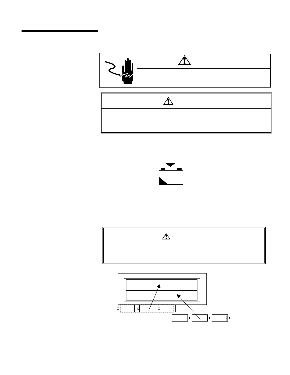
The battery symbol at the lower left of the display is used to indicate low battery power.
The cursor above the battery symbol will illuminate when there is approximately 15
minutes of operation remaining.
+ -
Figure 4-1
When the cursor is “on” above the battery symbol, change the batteries as soon as
possible. To change the batteries:
1. Open the battery door on the rear of the WILDCAT terminal.
2. Remove the six batteries.
CAUTION
THE WILDCAT SCALE CANNOT RECHARGE BATTERIES. IF RECHARGEABLE
BATTERIES ARE USED, THEY MUST BE RECHARGED WITH A COMMERCIALLY
AVAILABLE RECHARGER THEN REINSTALLED INTO THE TERMINAL.
3. Insert six new or recharged “D” size batteries as illustrated on the battery housing.
Top
Figure 4-2 - Shown With Rear Battery Panel Removed
(12/00) 4-3
Page 28

METTLER TOLEDO WILDCAT Scale Technical Manual
4. Reinstall the rear cover over the batteries and press into place.
5. Test for proper operation.
The operating time for a new set batteries depends on how the scale is used. Estimates
(without backlight) are shown below. Using the backlight feature reduces battery life.
Continuous use 400 hrs (Approximately 17 days)
8 hours per day 500 hrs (Approximately 3 months)
Keyboard Replacement
1. Remove power by removing the six “D” size batteries from the rear battery
compartment and/or disconnecting the AC power adapter.
2. Remove the four screws securing the front and back halves of the cover.
3. Disconnect the keyboard tail from the Controller PCB. Discard the old front cover.
4. Connect the keyboard tail of the new front cover to J5 of the Controller PCB.
5. Secure the front cover to the back cover with the four screws.
6. Apply power then press and hold the ON/OFF (PRINT) key for 3 seconds.
Operation Battery Life
Controller PCB Replacement
7. Test the operation of the new keyboard.
To replace the PCB, follow the procedures below.
1. Remove power by removing the six “D” size batteries from the rear battery
compartment and/or disconnecting the AC power adapter.
2. Remove the four screws securing the front and back halves of the cover.
3. Disconnect the keyboard tail from the Controller PCB and set the front cover aside.
4. Disconnect the battery harness from the Controller PCB.
5. Disconnect the load cell cable from the J4 terminal strip on the Controller PCB.
6. Remove the two hex standoffs from the side of the enclosure that secures the serial
output connector to the back cover of the WILDCAT.
7. Remove the four screws that secure the Controller PCB to the back cover.
8. Using proper static electricity precautions, carefully remove the Controller PCB and
place it in a protective static bag.
9. Install the new Controller PCB using the same screws removed in the previous step.
10. Install the two hex standoffs to the side of the enclosure that secure the serial output
connector to the back cover of the scale. Reconnect the load cell cable.
11. Reconnect the AC adapter and battery harnesses removed previously.
12. Connect the keyboard tail of the front cover to J5 of the Controller PCB.
13. Secure the front cover to the back cover with the four screws.
14. Apply power to the scale then press and hold the ON/OFF key for 3 seconds.
15. Reprogram, recalibrate and test the operation of the new Controller PCB.
(12/00) 4-4
Page 29

Load Cell Replacement
Chapter 4: Maintenance and Troubleshooting
Parts Replacement and Adjustments
1. Remove power by removing the six “D” size batteries from the rear battery
compartment and/or disconnecting the AC power adapter.
2. Remove the four screws securing the front and back halves of the cover.
3. Disconnect the keyboard tail from the Controller PCB and set the front cover aside.
4. Disconnect the load cell wiring from the J4 terminal strip on the Controller PCB.
5. Loosen the grip bushing on the side of the enclosure enough to slide the load cell
cable out.
6. Remove the stainless steel platform from the base.
7. Loosen and remove the top load cell mounting bolts that secure the top frame to the
load cell.
8. Set the top frame and the load cell spacer aside.
9. Turn the WILDCAT scale on its side to access the bottom load cell bolts.
10. Loosen and remove the bottom load cell mounting bolts.
11. Remove the load cell from the base and pull the excess cable out through the
bottom of the column.
12. Reinstall a new load cell by following the steps above in reverse order.
Note - Lubricate the threads and under the head of the load cell mounting bolts before
reinstalling.
13. Using a torque wrench, tighten the load cell mounting bolts to the specifications
shown in Table 4-2.
MODEL METRIC ENGLISH
WS30R/WS30VR 20 N•m 15 ft•lbs
WS60R/WS60VR 20 N•m 15 ft•lbs
WS60LR/WS60LVR 20 N•m 15 ft•lbs
WS150R/WS150VR 30 N•m 22 ft•lbs
WW250VR 40 N•m 30 ft•lbs
WW500VR 80 N•m 55 ft•lbs
Table 4-2
14. After replacing a load cell, the overload stops must be checked and adjusted (if
needed). Refer to the next section for the overload stop adjustment procedure.
15. Thread the load cell cable through the column from the bottom.
16. Insert the load cell cable through the grip bushing on the side of the enclosure.
17. Connect load cell cable to the J4 terminal strip on the Controller PCB (Figure 2-2).
18. Tighten the grip bushing on the side of the enclosure to secure the load cell cable.
19. Connect the keyboard of the front cover to J5 of the Controller PCB.
20. Secure the front cover to the back cover with the four screws.
21. Coil the excess load cell cable and insert it into the column. A small length of tape
applied to the ends of the coils allows the cable to slide into the column easier.
22. Apply power to the scale. Press and hold the ON/OFF (PRINT) key for 3 seconds.
23. Recalibrate and test the operation of the new load cell.
(12/00) 4-5
Page 30
METTLER TOLEDO WILDCAT Scale Technical Manual
g
Overload Stop Adjustment
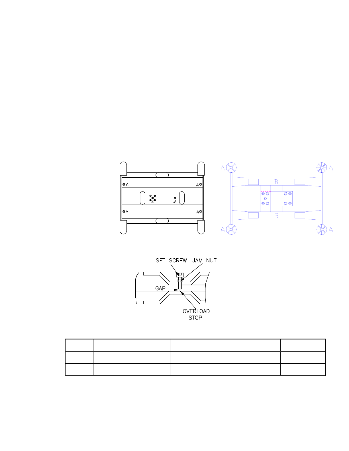
1. The overload stops must be checked and reset if the top or bottom frame or the load
cell has been replaced.
2. Remove the stainless steel platform from the base.
3. Using the proper size feeler gauge, check all six overload stops as shown in Figure
4-3. The correct gap measurements can be found in Table 4-3.
4. If the gaps are not set properly, proceed to the following steps.
5. Loosen the overload screw jam nuts. Refer to Figure 4-4.
6. Using the proper size feeler gauge, turn the screw until you feel a slight drag on the
feeler gauge.
7. Tighten the jam nut and recheck the gap. Readjust if necessary.
8. Adjust all six overload stops using this procedure.
9. Reinstall the platform and make sure the scale weighs to full capacity.
Figure 4-3a: WS models
Position
A
B
WS30R
Overload Gap
2 mm
(0.078 in)
0.75 mm
(0.03 in)
Overload Gap
WS60R
2 mm
(0.078 in)
0.75 mm
(0.03 in)
Fi
ure 4-4
WS60LR
Overload Gap
4 mm
(0.157 in)
1 mm
(0.04 in)
WS150R
Overload Gap
4 mm
(0.157 in)
1 mm
(0.04 in)
Figure 4-3b: WW models
WW250VR
Overload Gap
4mm
.16 in
1 mm
.04 in
WS500VR
Overload Gap
6 mm
.24 in
1.2 mm
.05 in
(12/00) 4-6
Page 31
Shift Test
Chapter 4: Maintenance and Troubleshooting
Parts Replacement and Adjustments
A shift test verifies that the scale weighs correctly irrespective of load placement. If the
scale does not pass the shift test, verify the overload stop gaps before replacing the load
cell. No adjustment for the shift is possible. If the scale does not pass the shift test, the
load cell must be replaced.
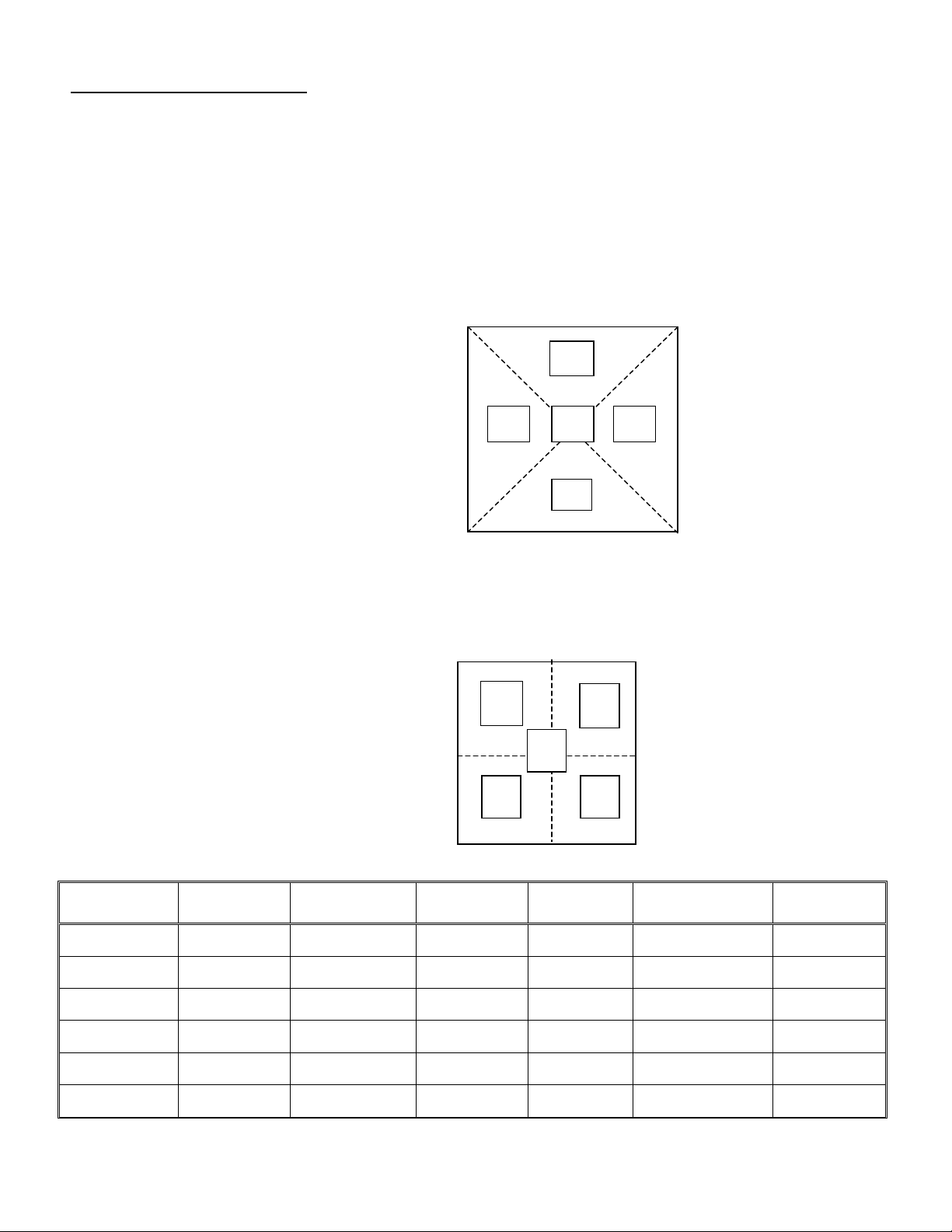
For NTEP and Canadian Weights and Measures tests, use weights equal to 1/2 the
scale’s capacity. Place the test weight sequentially at each of the positions A, B, C, D
and E as shown in Figure 4-5. These positions are the centers of the four quadrants of
the platform and the center of the platform. Note the terminal’s reading of the weight at
each position. The difference between any two positions in the shift test cannot exceed
the tolerance shown in Table 4-4.
A
E
BD
C
Figure 4-5
For an OIML test, use weights equal to 1/3 the scale’s capacity. Place the weight
sequentially at each of the positions A, B, C, D, and E as shown in Figure 4-6. These
positions are the centers of the four quadrants of the platform and center of the platform.
Note the terminal reading of the weights at each position. The difference between any
two positions in the shift test cannot exceed the tolerance shown in Table 4-4.
A
E
D
B
C
WS30R/WS30VR 30 kg/60 lb 0.01 kg/ 0.02 lb 15 kg/30 lb 10 kg/20 lb +/- 0.01 kg
WS60R/WS60VR 60 kg/150 lb 0.02 kg/ 0.05 lb 30 kg/75 lb 20 kg/50 lb +/- 0.02 kg
SCALE CAPACITY DISPLAY
INCREMENT
US and CANADA
TEST WEIGHT
WS60LR/WS60LVR 60 kg/150 lb 0.02 kg/ 0.05 lb 30 kg/75 lb 20 kg/50 lb +/- 0.02 kg
WS150R/WS150VR 150 kg/300 lb 0.05 kg/0.1 lb 75 kg/150 lb 50 kg/100 lb +/- 0.05 kg
WW250VR 250 kg/500 lb 0.1 kg/0.2 lb 125 kg/250 lb 80kg/170 lb +/-0.1 kg
WW500VR 500 kg/1000 lb 0.2 kg/0.5 lb 250 kg/500 lb 170 kg/350 lb +/- 0.2 kg
Table 4-4
Figure 4-6
OIML TEST
WEIGHT
TOLERANCE (NEW) TOLERANCE (IN
+/- 0.02 lb
+/-0.05 lb
+/- 0.05 lb
+/- 0.1 lb
+/-0.2 lb
+/- 0.5 lb
SERVICE)
+/- 0.02 kg
+/- 0.04 lb
+/- 0.04 kg
+/- 0.1 lb
+/- 0.04 kg
+/- 0.1 lb
+/- 0.10 kg
+/- 0.2 lb
+/- 0.2 kg
+/- 0.4 lb
+/- 0.4 kg
+/- 1.0 lb
(12/00) 4-7
Page 32

METTLER TOLEDO WILDCAT Scale Technical Manual
Power-Up Sequence
Upon power up, showing all numbers 0-9 checks the display, and a diagnostic self test
is performed on the memory and microprocessor. An error message is displayed if any
component fails the test. The program number [125362] is shown next, followed by the
revision [Sr. 2.00].
If everything tests okay, the WILDCAT scale will show [ 0.00] on the display. The
power-up sequence requires a few seconds to complete.
(12/00) 4-8
Page 33
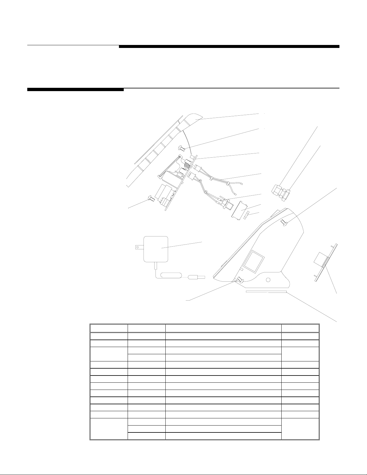
1
5 Parts List
Terminal
2
Chapter 5: Parts List
1
8
2
2
3
3
4
4
5
5
6
6
7
7
8
9
9
2
2
12
12
2
2
Item
Item P/N
ItemItem
P/N Description
P/NP/N
Description Quantity
DescriptionDescription
Quantity
QuantityQuantity
1 127482OTC Front Cover, Keyboard & Overlay Assembly 1
2 R0512000A Screw, M4 x 6 8
127483OTC Main PCB w/ Backlight 3
127484OTC Main PCB w/o Backlight
1
4 124466OTC Battery Harness 1
5 124467OTC Power Supply Harness 1
6 124454OTC Power Supply Plate 1
7 121101OTC Nut, Power Supply 1
8 12901800A Grip Bushing 1
9 14577900A Grip Bushing Nut 1
10 124453OTC Battery Cavity Cover Plate 1
11 124464OTC Rubber Bar 2
12
124474OTC Wall Adapter, 120 VAC, US Plug
125967OTC Wall Adapter, 220 VAC, US Plug
1
125969OTC Wall Adapter, 230 VAC, EU Plug
10
11
10
11
(12/00) 5-1
Page 34
METTLER TOLEDO WILDCAT Scale Technical Manual
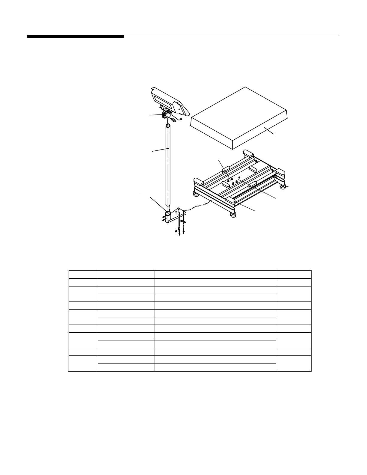
Column and Base (WS30,
WS60, WS60L, WS150)
1
6
2
3
4
7
5
8
Figure 5-1
Item P/N Description Quantity
1 126431OTC Indicator Bracket Assembly 1
125105OTC Stainless Steel Column, 350 mm high 2
1
125103OTC Stainless Steel Column, 680 mm high
3 123775OTC Column Bracket 1
123976OTC Load Cell, 100 kg (WS30R, WS60R, WS60LR) 4
5 102504OTC
123979OTC Load Cell, 250 kg (WS150R)
Load Cell Mounting Bolts, M6 × 25
125883OTC Stainless Steel Platter, (WS30R,WS60R) 6
1
8
1
125881OTC Stainless Steel Platter, (WS60LR,WS150R)
7 125009OTC Adjustable Foot 4
125006OTC Rubber Platter Supports (WS60LR,WS50R) 8
4
125924OTC Rubber Platter Supports (WS30R,WS60R)
Figure 5-2
(12/00) 5-2
Page 35
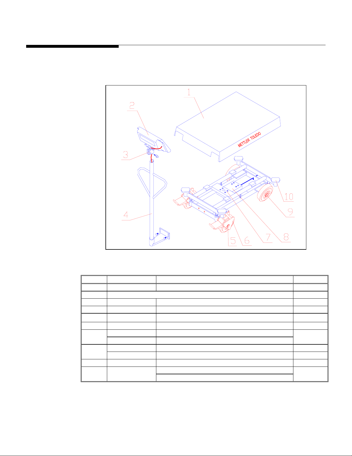
Column and Base (WW250
and WW500)
Chapter 5: Parts List
Column and Base (WW250 and WW500)
Item P/N Description Quantity
1 134926OTC
Stainless Steel Platter, 500 × 700mm
1
2 Terminal - Refer to page 5-1
3 126431OTC Indicator Bracket Assembly 1
4 134929OTC Column Assembly 1
5 102438OTC
Wheel Mounting Bolts, M12 × 90
6 131702OTC 4” Polyurethane Wheel Set (2 wheels with brakes) 4
114657OTC Load Cell, BMI-500 kg 7
118283OTC Load Cell, BMI-1000 kg
118033OTC
102527OTC
9 102440OTC
Load Cell Mounting Bolts, M10 × 60
Load Cell Mounting Bolts, M12 × 70
Wheel Mounting Bolts, M12 × 110 (for brakes)
Rubber Platter Supports (WW250VR) 10 136634OTC
Rubber Platter Supports (WW500VR)
1
8 8
8
4
(12/00) 5-3
Page 36

METTLER TOLEDO WILDCAT Scale Technical Manual
NOTES
(12/00) 5-4
Page 37
6 Appendices
Appendix 1: Demand
Mode Output
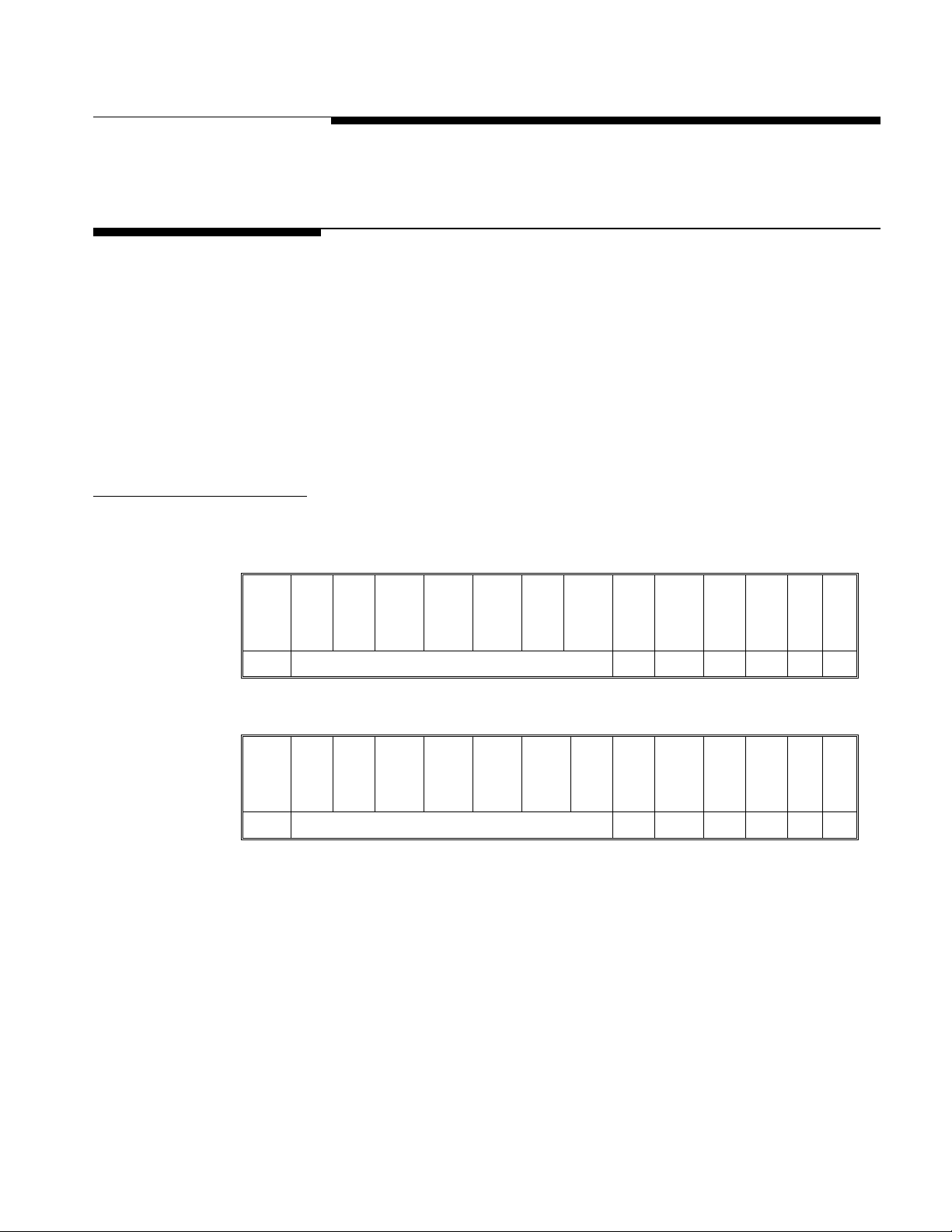
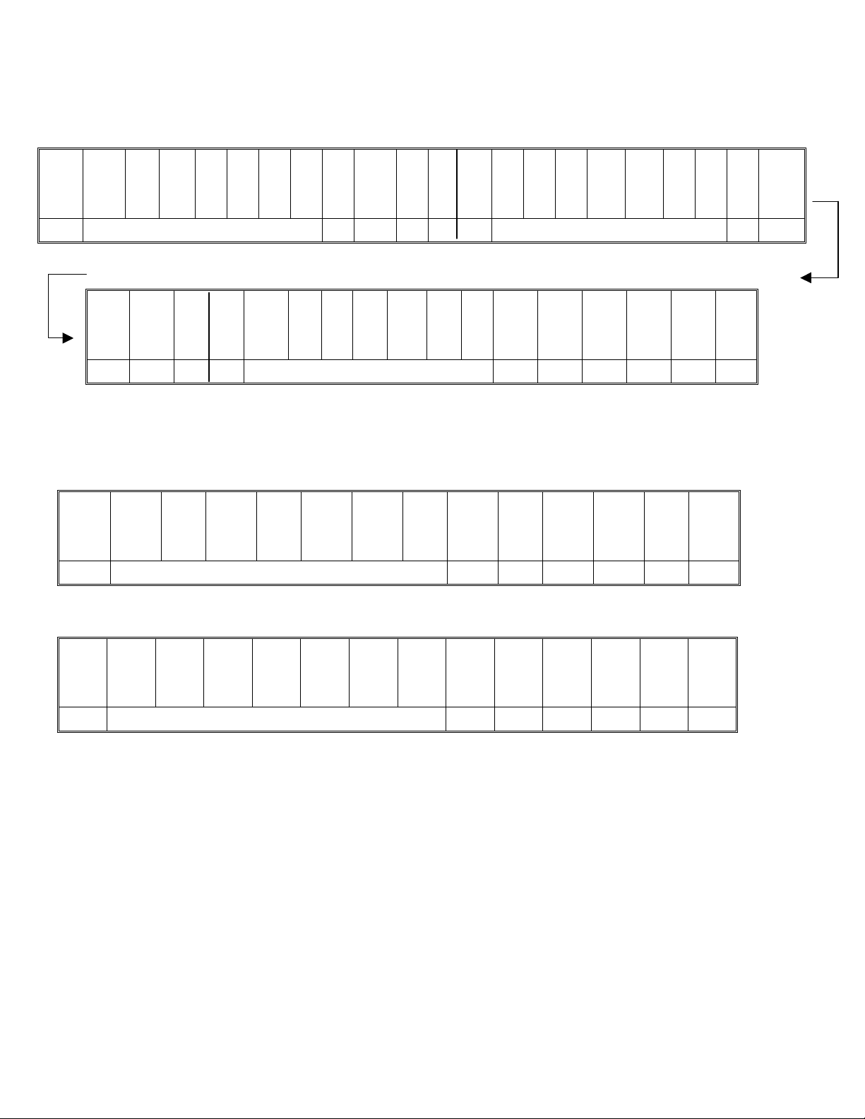
Demand mode output occurs when a print request is received form the PRINT push
button. The line format, baud rate, character length, and parity are selectable in the
programming mode.
Demand mode output is blocked when the scale is “in motion” or when the weight is
below 20d of gross weight or over capacity. When one of those situations occurs,
the print request is ignored and is not buffered. Zero must be captured at powerup
before a demand mode output can occur. After one output, the WILDCAT scale must
see motion before it will send data again.
Weight Field Format
Displayed Weight Format (Gross or Net)
Data M
Note 3 4 5 4 2 6 8
- - - - - L
S
D
Chapter 6: Appendices
Appendix 1: Demand Mode Output
S
Units S P B C R L
S
P
D
F
Table 6-1: Gross Weight
Data M
Note 9 4 5 4 10 6 8
- - - - - L
S
D
Table 6-2: Net Weight
S
Units S P N C R L
S
P
D
F
(12/00) 6-1
Page 38
METTLER TOLEDO WILDCAT Scale Technical Manual
Single Line – Gross, Tare, Net Weights
Single-line gross weight format is output if no tare weight has been taken.
Data M
Note 3 4 5 4 2 4 3 4 5
Data S P T S
Note 4 10 4 9 4 5 4 10 6 8
- - - - - L
S
D
P
S P Units S P B S
S
D
M
- - - - - L
S
D
P M S
S
D
- - - - - L
D
S
P
Units S P N C R L
S P Units
S
D
F
Table 6-3: Single Line – Gross, Tare, Net Weights
Multiple Line – Gross, Tare, Net Weights
If no tare weight has been taken, only the gross weight field is output.
Data M
S
D
Note 3 4 5 4 2 6 8
- - - - - L
S
S
P
D
Units S P B C R L
F
Table 6-4: Multiple Line – Gross Weight
Data M
S
D
Note 4 5 4 10 6 8
- - - - - L
S
D
Table 6-5: Multiple Line – Tare Weight
S
Units S P T C R L
P
F
(12/00) 6-2
Page 39

Chapter 6: Appendices
Appendix 1: Demand Mode Output
Data M
S
D
Note 9 4 5 4 10 6 8
- - - - - L
S
D
Table 6-6: Multiple Line – Net Weight
S
P
Units S P N C R L
F
Demand Format Notes
2 Gross weight legend. Selectable in the programming mode as a space, “B” for
bruto or “G” for gross.
3 The gross weight data fields are padded with leading spaces to 7 digits.
4 ASCII Space <SP> character, hex value 20.
5 Weight units (lb, kg, g) as selected in setup and by the FUNCTION key.
6 ASCII Carriage Return <CR> character, hex value OD.
7 Optional checksum character: Checksum is defined as the 2’s complement of the
seven low order bits of the binary sum of all characters preceding the checksum
character, including the <STX> and <CR> characters. The checksum calculation
for multiple lines of data includes the <LF> character from the previous line of
data.
8 ASCII Line Feed <LF> character, hex value OA.
9 The net weight field is right justified and padded with spaces to seven digits.
A negative net weight is indicated by a minus character before the most
significant digit of the weight value. For example, a weight of –55.00 is printed
with one leading space (sp=space): sp-55.00.
10 Weight field descriptors. The “TR” and “N” legends are printed (for net weight)
after the tare and net weight fields to identify them.
(12/00) 6-3
Page 40
METTLER TOLEDO WILDCAT Scale Technical Manual
Appendix 2: Continuous
Mode Output
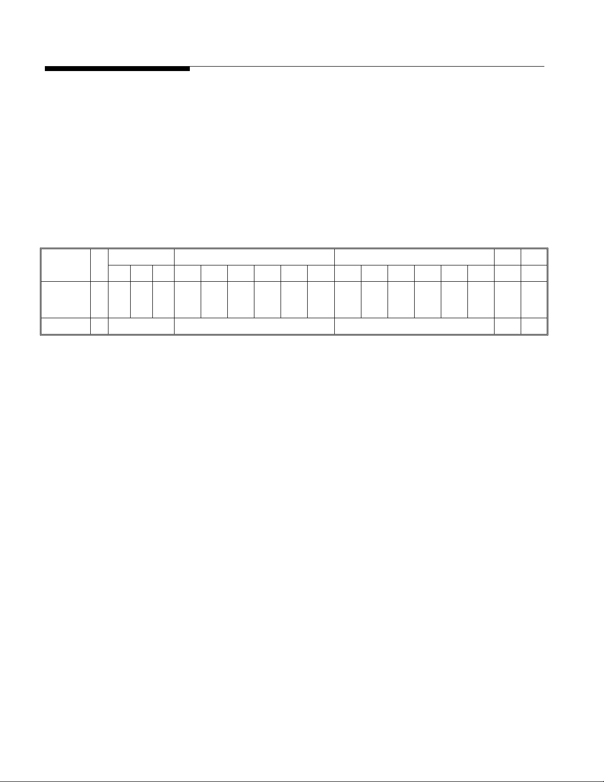
The continuous output format is output as the display is updated (approximately 7
times per second). The format is fixed except for baud rate, data bits, stop bits,
parity, and the selectable checksum character. The continuous output mode provides
compatibility with METTLER TOLEDO products that require real-time weight data (for
example, Models 8624, 9323, 9325, and other accessories).
Continuous data output at a 1200-baud rate will slow the display update rate. Use
4800 baud or faster to maintain the maximum update rate.
The continuous output includes status bytes that indicate the operating conditions in
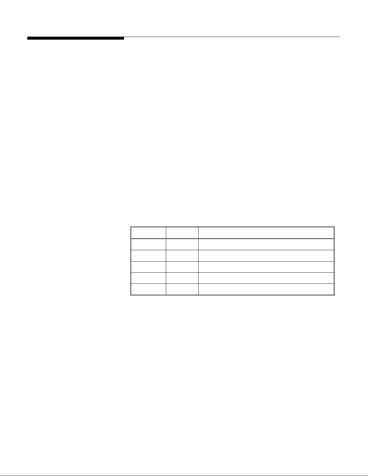
the terminal.
Status Indicated Weight Tare Weight Character 1
2 3 4 5 6 7 8 9 10 11 12 13 14 15 16 17 1
C
- - - - L
Data S
Note 1 2 3 4 5 6
S
S
W
W
W
T
D
C
B
A
X
- - - - L
M
S
S
M
S
S
D
D
S
D
C
R
H
K
Table 6-8: Continuous Format Output
Continuous Format Notes
1 ASCII Start of Text <STX> character, hex value 02.
2 SWA, SWB, and SWC: Status Words A, B, and C. Refer to Tables 6-9, 6-10, and
6-11 for status bytes.
3 Displayed weight: Six digits of displayed weight. No decimal point in field.
4 Tare weight: Six digits of tare weight data. No decimal point in field.
5 ASCII Carriage Return <CR> character, hex value OD.
6 Optional checksum character: Checksum is defined as the 2’s complement of the
seven low order bits of the binary sum of all characters preceding the checksum
character, including the <STX> and <CR> characters.
(12/00) 6-4
Page 41
Status Byte Definition
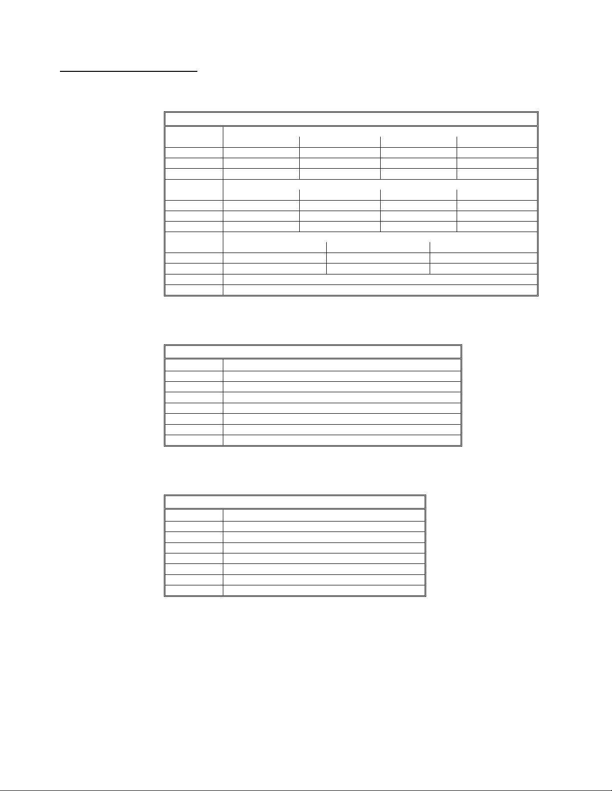
The following tables detail the status bytes for the standard continuous output.
Bit Identification Table For Status Byte A
Bit
0
1
2
0
1
2
3
4
5
6
XXXX00 XXXXX0 XXXXXX XXXXX.X
0 1 0 1
0 0 1 1
0 0 0 0
XXXX.XX XXX.XXX XX.XXXX X.XXXXX
0 1 0 1
0 0 1 1
1 1 1 1
X1 X2 X5
1 0 1
0 1 1
Table 6-9
Bit Identification Table For Status Byte B
Bit
0
1
2
3
4
5
6
lb = 0, kg = 1 (see also Byte C, bits 0, 1, 2)
Gross = 0, Net = 1
Sign, Positive = 0, Negative = 1
Out of Range = 1, In Range = 0
Power-up Not Zeroed = 1
Table 6-10
Bit Identification Table For Status Byte C
Bit
0
1
2
3
4
5
6
Expand Weight Display = 1
Function
lb or kg = 0, grams = 1
Always = 0
Always = 0
Print Request = 1
Always = 1
Always = 0
Table 6-11
Chapter 6: Appendices
Dummy Zero or Decimal Position
Dummy Zero or Decimal Position
Increment Size
Always = 1
Always = 0
Function
Motion = 1
Always = 1
(12/00) 6-5
Page 42
METTLER TOLEDO WILDCAT Scale Technical Manual
Appendix 3: ASCII Input
Commands
Beginning with software version 2.00, the WILDCAT scale has the ability to receive
certain ASCII characters via the serial port to perform simple keyboard functions.
Previous versions of software did not have this capability. The software version can be
viewed at power up.
The ASCII input commands will operate when the serial port is programmed for either
demand output or continuous output. The input character format must be the same as
the data output format selected in setup including baud rate, data bits, parity and stop
bits. The remote commands are subject to the same restrictions as the keyboard
equivalents. For instance, tare, zero and print commands will only operate if sent when
there is no motion on the scale. When sending multiple commands, there must be a
time delay of at least one-half second (500 milliseconds) between each remote ASCII
command character.
These ASCII commands duplicate the front panel functions. Note that all characters are
uppercase and no control characters such as <CR> (carriage return) or <LF> (line feed)
need to be sent. If they are sent, they will be ignored. All ASCII characters other than the
ones listed below will also be ignored.
The following commands are recognized by the WILDCAT scale when the output mode
is programmed as either demand mode or continuous output.
Command Function Description
C Clear Clear tare value
T Tare Performs a pushbutton tare
P Print Transmit data or set print bit in continuous output
S Print Transmit data or set print bit in continuous output
Z Zero Zero the scale (if within range and no-motion)
(12/00) 6-6
Page 43
Chapter 6: Appendices
Appendix 4: GEO Codes
Appendix 4: GEO Codes
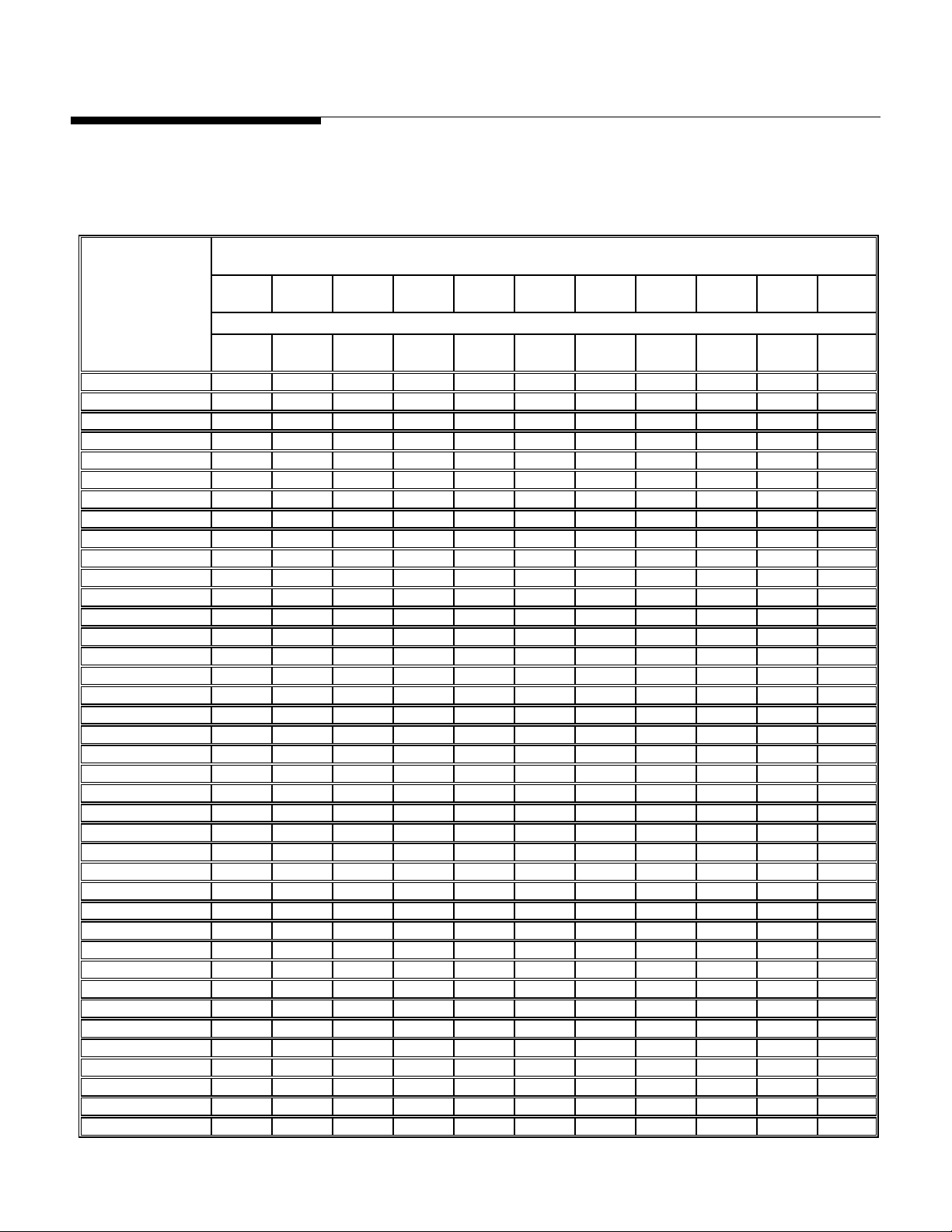
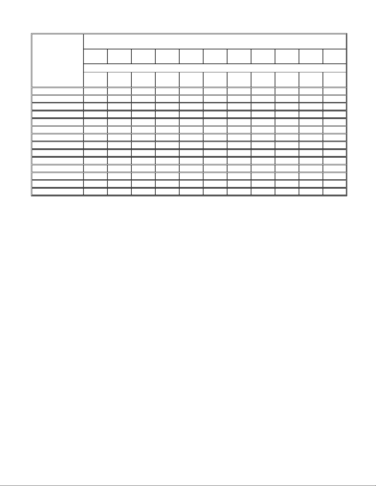
Use the following Geo Codes if you relocate the WILDCAT scale to a location other than
the original location where it was calibrated.
Northern
and
Southern
Latitude
in
Degrees and Minutes 0
0° 0′ —5° 46′ 5 4 4 3 3 2 2 1 1 0 0
5° 46′ — 9° 52′ 5 5 4 4 3 3 2 2 1 1 0
9° 52′ — 12° 44′ 6 5 5 4 4 3 3 2 2 1 1
12° 44′ — 15° 6′ 6 6 5 5 4 4 3 3 2 2 1
15° 6′ — 17° 10′ 7 6 6 5 5 4 4 3 3 2 2
17° 10′ — 19° 2′ 7 7 6 6 5 5 4 4 3 3 2
19° 2′ — 20° 45′ 8 7 7 6 6 5 5 4 4 3 3
20° 45′ — 22° 22′ 8 8 7 7 6 6 5 5 4 4 3
22° 22′ — 23° 54′ 9 8 8 7 7 6 6 5 5 4 4
23° 54′ — 25° 21′ 9 9 8 8 7 7 6 6 5 5 4
25° 21′ — 26° 45′ 10 9 9 8 8 7 7 6 6 5 5
26° 45′ — 28° 6′ 10 10 9 9 8 8 7 7 6 6 5
28° 6′ — 29° 25′ 11 10 10 9 9 8 8 7 7 6 6
29° 25′ — 30° 41′ 11 11 10 10 9 9 8 8 7 7 6
30° 41′ — 31° 56′ 12 11 11 10 10 9 9 8 8 7 7
31° 56′ — 33° 9′ 12 12 11 11 10 10 9 9 8 8 7
33° 9′ — 34° 21′ 13 12 12 11 11 10 10 9 9 8 8
34° 21′ — 35° 31′ 13 13 12 12 11 11 10 10 9 9 8
35° 31′ — 36° 41′ 14 13 13 12 12 11 11 10 10 9 9
36° 41′ — 37° 50′ 14 14 13 13 12 12 11 11 10 10 9
37° 50′ — 38° 58′ 15 14 14 13 13 12 12 11 11 10 10
38° 58′ — 40° 5′ 15 15 14 14 13 13 12 12 11 11 10
40° 5′ — 41° 12′ 16 15 15 14 14 13 13 12 12 11 11
41° 12′ — 42° 19′ 16 16 15 15 14 14 13 13 12 12 11
42° 19′ — 43° 26′ 17 16 16 15 15 14 14 13 13 12 12
43° 26′ — 44° 32′ 17 17 16 16 15 15 14 14 13 13 12
44° 32′ — 45° 38′ 18 17 17 16 16 15 15 14 14 13 13
45° 38′ — 46° 45′ 18 18 17 17 16 16 15 15 14 14 13
46° 45′ — 47° 51′ 19 18 18 17 17 16 16 15 15 14 14
47° 51′ — 48° 58′ 19 19 18 18 17 17 16 16 15 15 14
48° 58′ — 50° 6′ 20 19 19 18 18 17 17 16 16 15 15
50° 6′ — 51° 13′ 20 20 19 19 18 18 17 17 16 16 15
51° 13′ — 52° 22′ 21 20 20 19 19 18 18 17 17 16 16
52° 22′ — 53° 31′ 21 21 20 20 19 19 18 18 17 17 16
53° 31′ — 54° 41′ 22 21 21 20 20 19 19 18 18 17 17
54° 41′ — 55° 52′ 22 22 21 21 20 20 19 19 18 18 17
55° 52′ — 57° 4′ 23 22 22 21 21 20 20 19 19 18 18
57° 4′ — 58° 17′ 23 23 22 22 21 21 20 20 19 19 18
58° 17′ — 59° 32′ 24 23 23 22 22 21 21 20 20 19 19
0
325
1060
325
650
1060
2130
650
975
2130
3200
975
1300
3200
4260
Height above sea-level in meters
1300
1625
Height above sea-level in feet
4260
5330
1625
1950
5330
6400
1950
2275
6400
7460
2275
2600
7460
8530
2600
2925
8530
9600
2925
3250
9600
10660
3250
3575
10660
11730
(12/00) 6-7
Page 44
METTLER TOLEDO WILDCAT Scale Technical Manual
Northern
and
Southern
Latitude
in
Degrees and Minutes 0
59° 32′ — 60° 49′ 24 24 23 23 22 22 21 21 20 20 19
60° 49′ — 62° 9′ 25 24 24 23 23 22 22 21 21 20 20
62° 9′ — 63° 30′ 25 25 24 24 23 23 22 22 21 21 20
63° 30′ — 64° 55′ 26 25 25 24 24 23 23 22 22 21 21
64° 55′ — 66° 24′ 26 26 25 25 24 24 23 23 22 22 21
66° 24′ — 67° 57′ 27 26 26 25 25 24 24 23 23 22 22
67° 57′ — 69° 35′ 27 27 26 26 25 25 24 24 23 23 22
69° 35′ — 71° 21′ 28 27 27 26 26 25 25 24 24 23 23
71° 21′ — 73° 16′ 28 28 27 27 26 26 25 25 24 24 23
73° 16′ — 75° 24′ 29 28 28 27 27 26 26 25 25 24 24
75° 24′ — 77° 52′ 29 29 28 28 27 27 26 26 25 25 24
77° 52′ — 80° 56′ 30 29 29 28 28 27 27 26 26 25 25
80° 56′ — 85° 45′ 30 30 29 29 28 28 27 27 26 26 25
85° 45′ — 90° 00′ 31 30 30 29 29 28 28 27 27 26 26
0
325
1060
325
650
1060
2130
650
975
2130
3200
975
1300
3200
4260
Height above sea-level in meters
1300
1625
Height above sea-level in feet
4260
5330
1625
1950
5330
6400
1950
2275
6400
7460
2275
2600
7460
8530
2600
2925
8530
9600
2925
3250
9600
10660
3250
3575
10660
11730
(12/00) 6-8
Page 45

Page 46

METTLER TOLEDO
Scales & Systems
1900 Polaris Parkway
Columbus, Ohio 43240
Phone (US and Canada) (800) 786-0038
(614) 438-4511
(All Others) (614) 438-4888
Internet: www.mt.com
E15609900A
(12/00).01
METTLER TOLEDO® is a registered trademark of Mettler-Toledo, Inc.
©2000 Mettler-Toledo, Inc.
E15609900A
 Loading...