

Page 1
Page 2

Service manual
WILD M690
Surgical microscope
Legal questions / Safety
Optics carrier
2
X/Y unit
Binocular tube T
3
4
Base rollable MS-C
5
Page 3

Service manual M690x
Legal questions / Safty-Rechtsfragen /Sicherheit
11/93 3688-BZ
Inhaltsverzeichnis / Table of Contents
Kapitel
Rechtsfragen / Legal questions
.....................................................................................
Question juridiques / Cuestiones de derecho
Sicherheit / Safety / Securite / Seguridad
......................................................................
..................................................................
Seite
1
2
3
Page 4
Service manual M690
Legal questions / Safty-Rechtsfragen / Sicherheit
11/93 3688-BZ
Copyright
Ohne vorherige schriftliche Erlaubnis der Firma Leica AG, Heerbrugg (Schweiz), darf dieses Dokument
weder insgesamt noch auszugsweise mit mechanischen, fotografischen, elektronischen oder irgendwelchen
anderen Mitteln (einschließlich ihrer Umwandlung oder Übertragung in maschinenlesbarer Form) kopiert,
in einem Informationsspeicher abgelegt, außerhalb des dafür vorgesehenen Zwecks oder in irgend einer
Form an von Leica AG, Heerbrugg nicht ausdrücklich befugte Dritte zugänglich gemacht oder abgegeben
werden
Haftung
Dieses Dokument richtet sich ausschließlich an qualifizierte Servicetechniker und Servicetechnikerinnen,
welche über die notwendigen Fachkenntnisse verfügen
Qualifizierte Servicetechniker und Servicetechnikerinnen sind solche, die den entsprechenden Servicekurs
bei Leica AG, Heerbrugg erfolgreich besucht haben und bei Unternehmen der Leica Gruppe oder bei von
Leica AG, Heerbrugg autorisierten Vertretungen oder Servicewerkstätten tätig sind
Wird dieses Dokument von nicht qualifizierten Servicetechniker und Servicetechnikerinnen verwendet, so
lehnt Leica AG, Heerbrugg jegliche Haftung ab für direkte und indirekte Schäden, die durch nicht
fachgemäße Anwendung und/oder Interpretation dieses Dokumentes entstehen
Copyright
Without prior permission in writing by Leica AG, Heerbrugg (Switzerland), this document shall not be
reproduced as a whole or in part, by mechanical, photographic, electronic, or other means (including into or
transmission in machine-readable form); stored in any retrieval System; used for any purpose other than
that/those for which it is intended; nor made accessible or communicated in any form to any third party not
expressly authorized by Leica AG, Heerbrugg to have access thereto.
Liability
‘Ibis document is strictly for the use of qualified service engineers with the requisite technical skills.
Only persons who have successfully completed the appropriate service training provided by Leica AG,
Heerbrugg and are in the employ of a Company in the Leica Group or of an agency, distributor, or Service
workshop duly authorized by Leica AG, Heerbrugg have the status of qualified Service engineer.
Leica AG, Heerbrugg accepts no liability whatever for direct or indirect darnage that may occur due to the
unauthorized or improper use or interpretation of this document by any person who is not a qualified
service engineer in accordance with the above definition.
Page 5
Service manual M690
Legal questions / Safty-Rechtsfragen / Sicherheit
11/93 3688-BZ
Sie verstehen und befolgen die Sicherheitsinformationen und die Instruktionen auf dem Produkt sowie in
der Gebrauchsanleitung.
Sie kennen die ortsüblichen gesetzlichen, betrieblichen und ausserbetrieblichen
Unfallverhütungsvorschriften im Wissen, dass sich diese auf dem aktuellsten Stand befinden.
Sie benachrichtigen Leica schriftlich, sobald an der Ausrüstung Sicherheitsmängel auftreten.
Service technicians have the following obligations:
l
To understand
l
To
be familiar with local regulations relating to industrial and non-industrial accident prevention in the
and follow the safety information and instructions on the product and in the user manual.
knowledge that these regulations are up to date.
l
To inform
Leica immediately in writing if the equipment becomes Unsafe.
Page 6

INHALTSVERZEICHNIS
CONTENTS
Seite/Page
Testbox M690
Testbox M690
TRIEBKASTEN
DRIVE HOUSING
Focus Zoom Board, Mikroschalter
Focus Zoom Board, Microswitches
Demontage Triebkasten vom Optikträger
Seperate Drive housing and optics carrier
Focusmotor
Focusmotor
Spindel, Rollenführung
Threaded spindle, roller bearing
1,2
3-5
6
7,8
9-11
OPTIKTRÄGER
OPTICS CARRIER
Ober-und Unterteil trennen
Seperate upper-and lower part
Platine mit Zoomantrieb
Plate with zoom drive
Platine mit Zoomantrieb justieren
Adjust plate with zoom drive
Zoomeinheit
Zoom assembly
12,13
14-22
23-25
26-30
Page 7

Seite/Page
Zoomeinheit justieren
Adjust zoom assembly
Beleuchtungszoom
Zoom for illumination
Lampenschnellwechsler
Quickchange lamp mount
Beleuchtung justieren
Adjust illumination
Spezial Werkzeuge
Special tools
31-35
36-40
41-44
46-49
51,52
Page 8
INSTRUKTIONEN FÜR DEN ELEKTRISCHEN TEIL DES M690 SIND ENTHALTEN IM:
INSTRUCTIONS FOR THE ELECTRICAL PART OF THE M690 AR INCLUDED IN:
S E R V I C E M A N U A L M E L 2 7 / 4 6
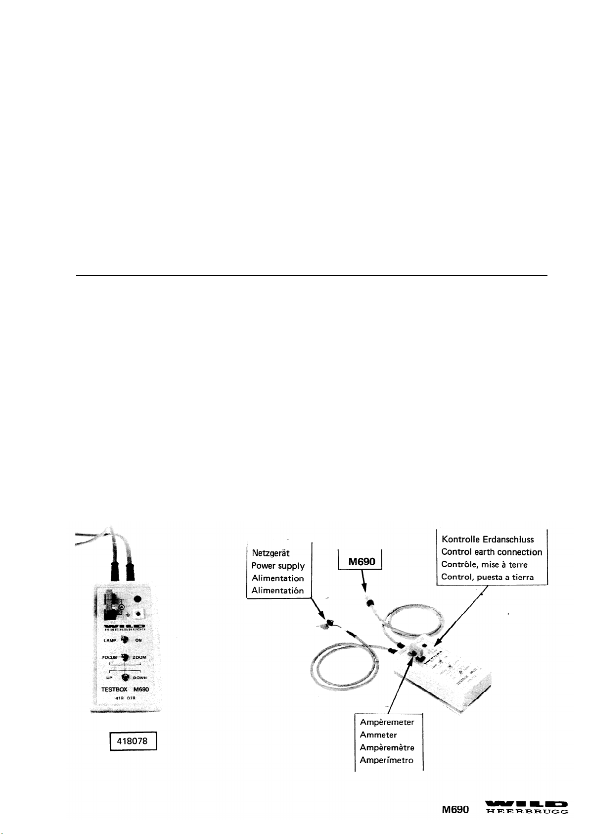
TESTBOX M690
Mit
der Testbox M690 können der Zoom-und Focusmotor und die Lampe ohne die Steuereinheit MEL27
betrieben werden. Notwendig ist ein Netzgerät
Spannung
Stromstärke =
=
12V
min. 2A
By using the M690 test box the zoom and focusing motor and the lamp can be set to work Without the
control unit. A power supply unit is necessary in addition to the test box
VoItage
Current
=
=
12v
min. 2A
1
Page 9
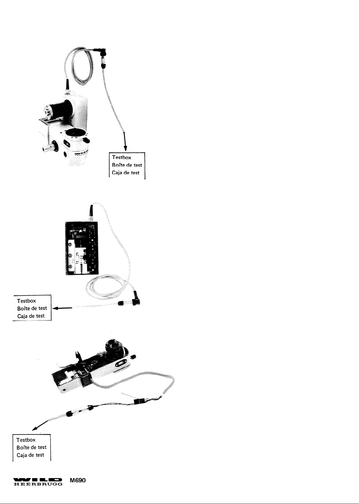
2
Anschluss Triebkasten und Optikträger an Testbox.
Connection of drive housing and optic carrier to the
test box.
Anschluss Triebkasten an Testbox.
Connection of drive housing to the testbox.
Anschluss Optikträger an Testbox.
Connection of optics carrier to the testbox.
Page 10
Page 11
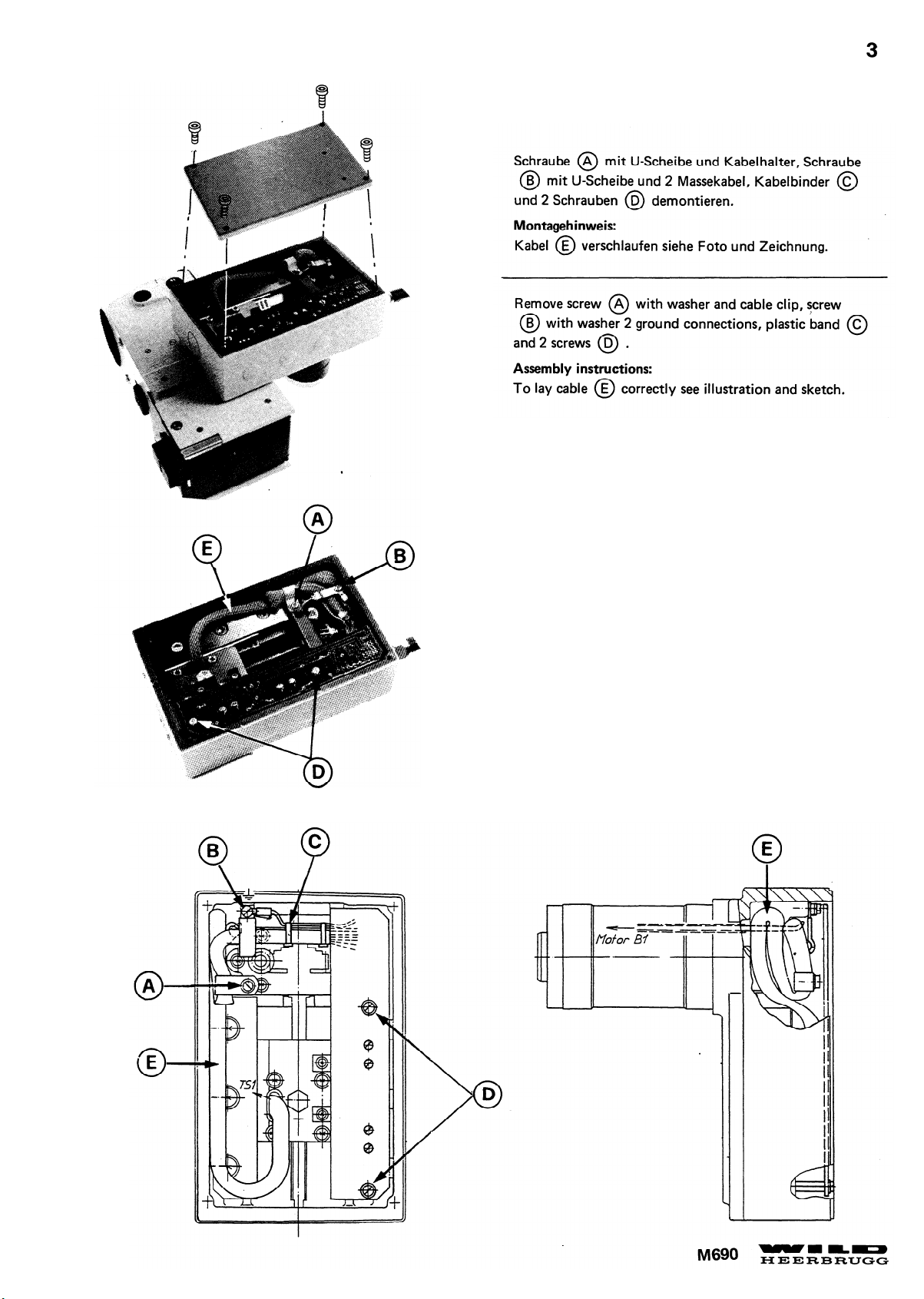
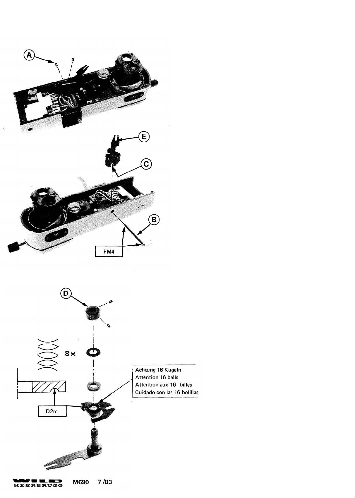
Focus Zoom Board (A) anheben und 3 Stecker (B)
(P17,18,19) au
sziehen und Focus Zoom Board demon-
tieren.
Montagehinweis:
- Beim Einstecken der Stecker auf Kordierung achten.
- Schaltpunkte der Mikroschalter S1 und S2 einstellen.
Siehe Seite 5.
Lift up Focus Zoom board (A) , pull out 3 plugs (B)
(P17,18,19) and remove Focus Zoom Board.
Assembly instruction:
- Ensure that the coded plugs are correctly inserted.
- For adjustment of switch point of the microswitches
S1 and S2, see page 5.
Page 12
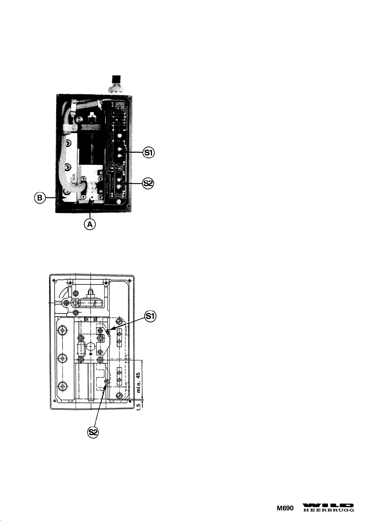
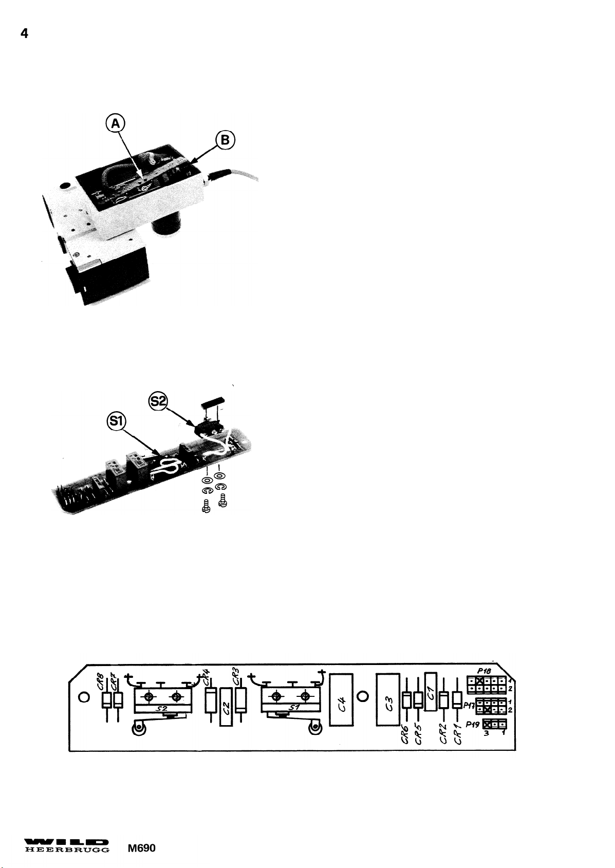
Mikroschalter Schaltpunkte einstellen.
1. Der untere Schalter S2 muss schalten, wenn die
untere Fläche des Schlittens (A) 1,5mm über
der unteren Fläche der Führungsleiste (B) steht.
2. Der Schaltpunkt des oberen Schalters S1 muss so
eingestellt sein, dass der Weg des Schlittens mind. 45mm
beträgt.
Korrekturen:
Schalter S1 oder S2 nach unten oder oben schieben.
Adjust switch points of microswitches;
1. Switching at the lower switch S2 must occur when
the lower face of carriage (A) is 1,5mm above the
lower face of the guide ledge (B).
2. The switch point of the upper switch S1 is correctly
adjusted when the carriage moves min. 45mm.
Correction:
Slide switch S1 or S2 up or down
Page 13
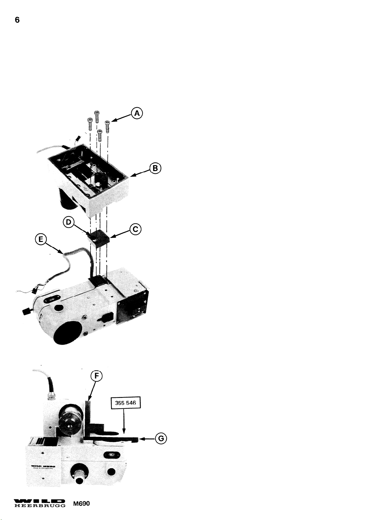
Die Demontage des Triebkastens vom Optikträger ist nicht für alle Servicearbeiten notwendig
Do not separate drive housing and optics carrier for any Service work.
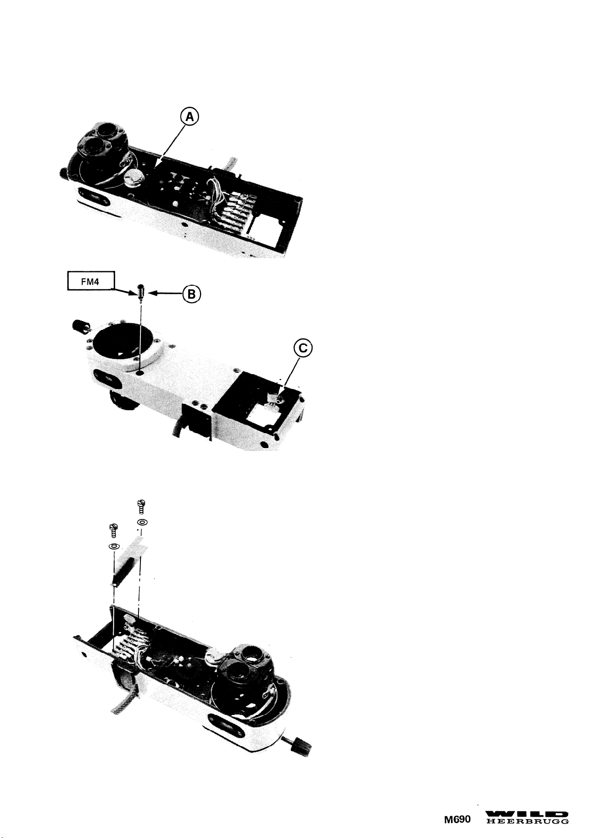
4 Schrauben (A) , Triebkasten (B) und Distanzplatte
(C) demontieren. Kabel (E) durch Schlitz (D) ziehen.
Montagehinweis:
Mit Winkel (F) und Platte (G) Triebkasten rechtwinklig
zur Tubusauflage ausrichten.
Remove 4 screws (A) , drive housing (B) spacer plate
(C) and pull out cable (E) through slit (D) .
Assembly instruction:
Align drive housing with bracket (F) and plate (G) at
right angle to supporting face of tube.
Page 14
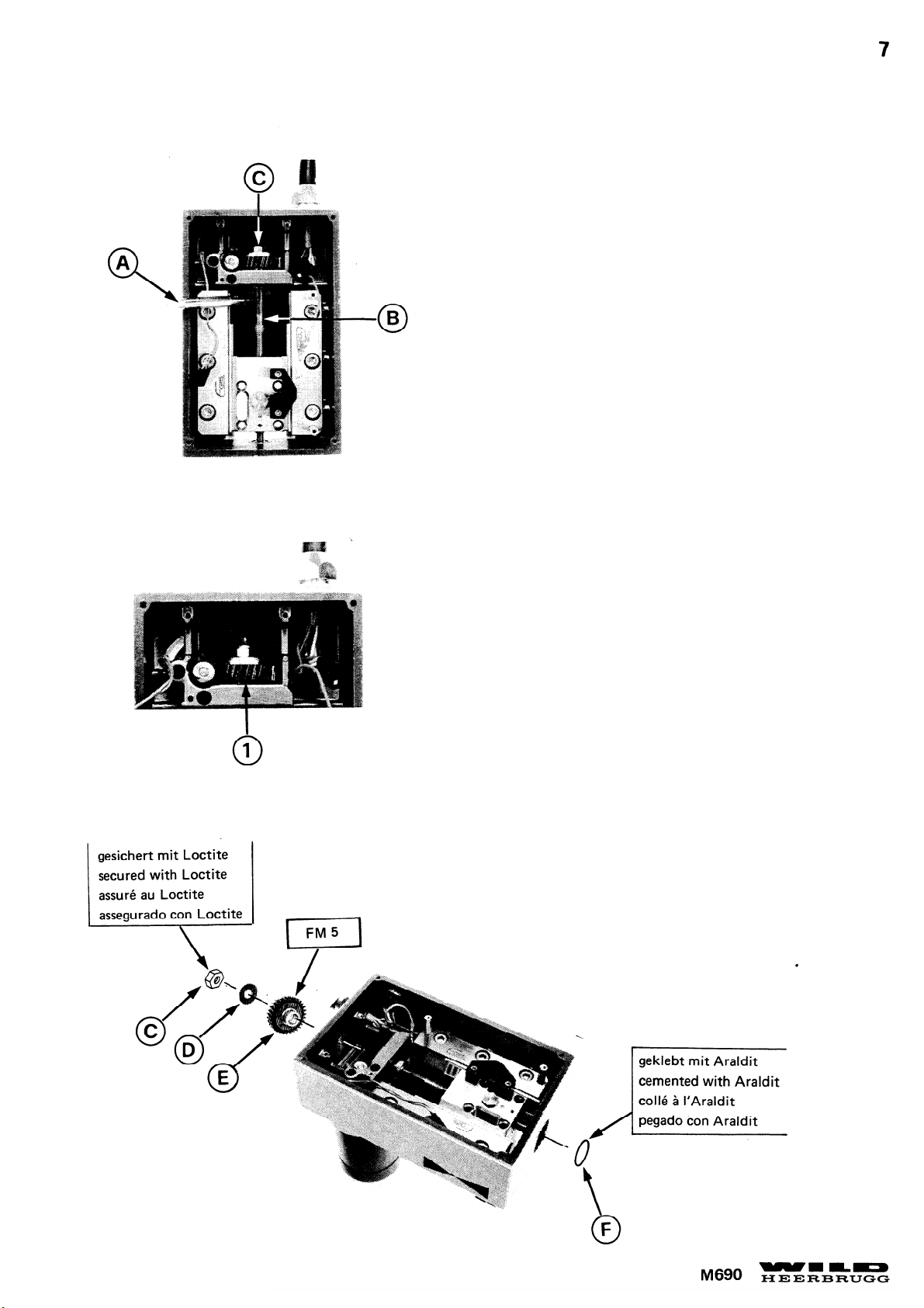
- Mit Durchschlag (A) Spindel (B) festhalten und
Mutter (C) ausschrauben.
- U-Scheibe (D) und Zahnrad (E) demontieren.
Hinweis:
Bei einigen Instrumenten der 1. Serie ist die
Spindel länger. Siehe Foto (1) . Bei diesen
Instrumenten muss zum Demontieren des
Zahnrades die Spindel nach unten geschoben
werden.
-
Hold spindle (B) with pin punch (A) and unscrew
nut (C) .
- Remove washer (D) and gearwheel (E) .
Note:
A longer spindle (B) is fitted in some instruments
of the firse production series. (see illustration (1))
In these instruments the spindle must be moved
downwards before removing the gearwheel (E) .
Page 15
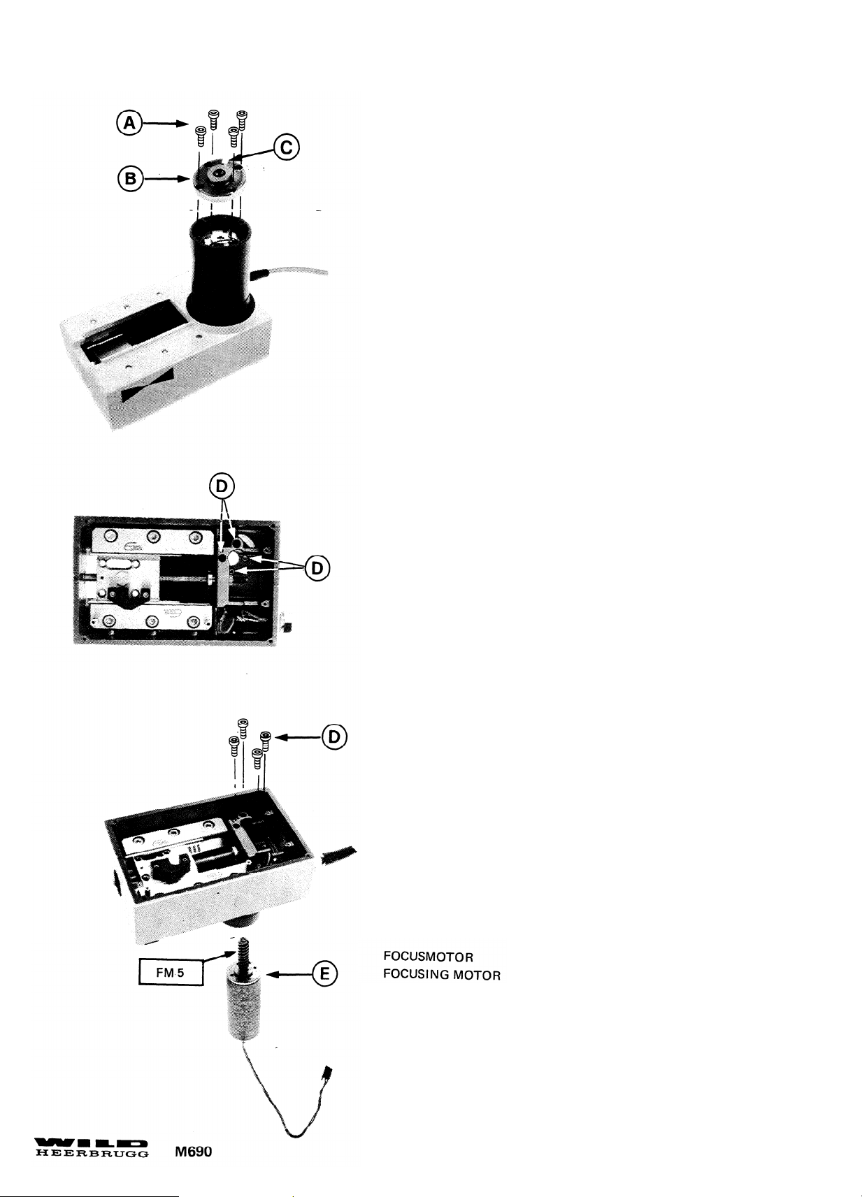
8
Montagehinweis:
- Durch Verschieben von Motor (E) Zahnradeingriff
einstellen.
- Flansch (B) mit Nute (C) in korrekter Position
montieren.
Assembly instructions:
- Adjust clearance of gear wheel by displacing motor (E)
- Fit flange (B) with slot (C) in correct Position.
Page 16
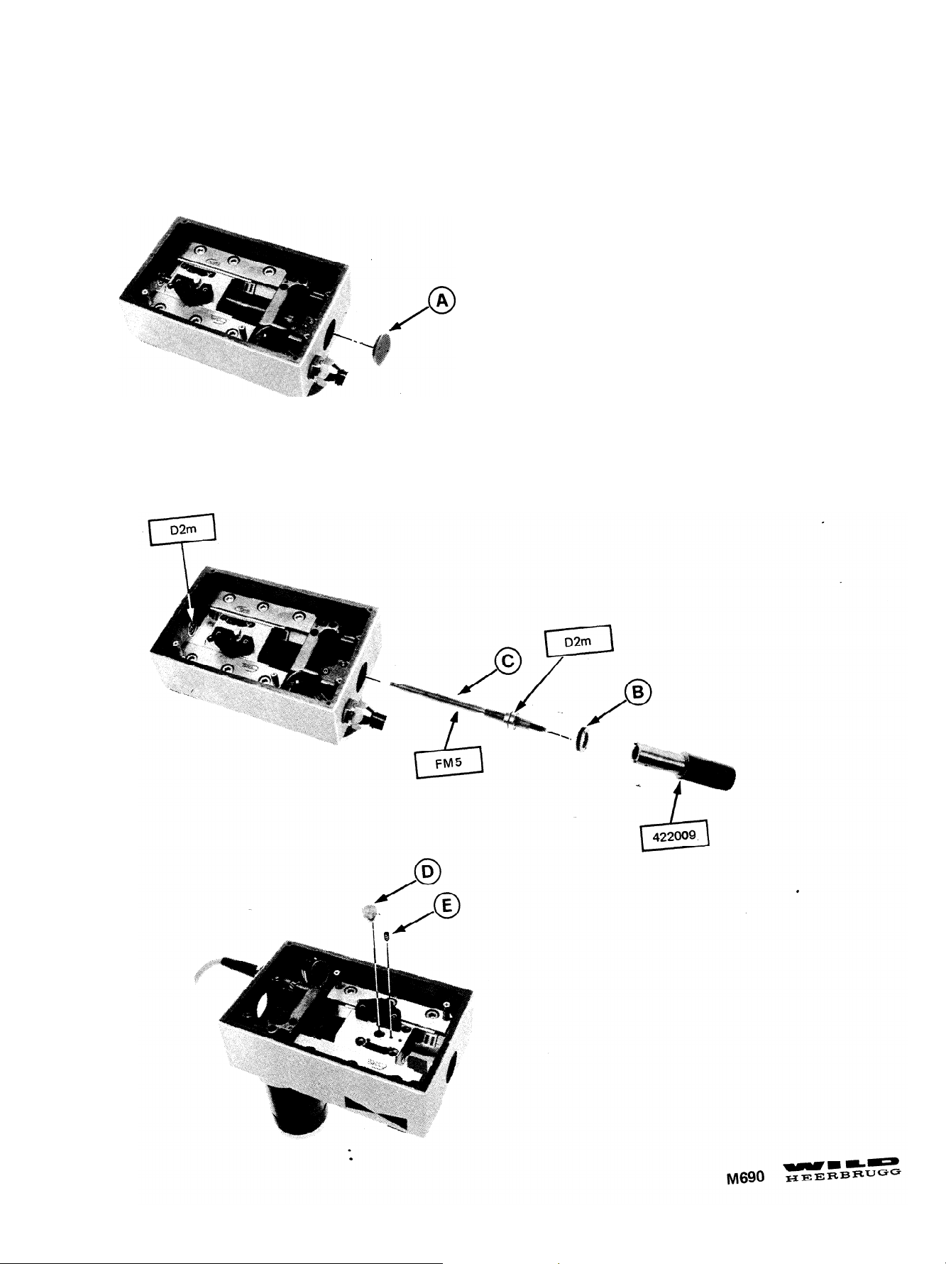
Deckel (A) Gewindering (B) und Gewinde-
Spindel (C) ausschrauben.
9
Unscrew cover
spindle (C) .
(A) , threaded ring (B) and threaded
Page 17
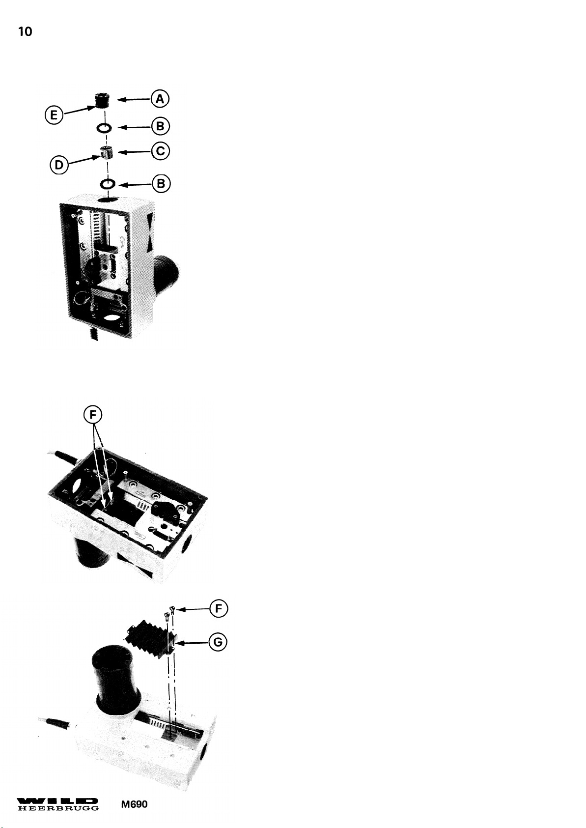
Montagehinweis:
-
U-Scheiben (B) mit beschichteter Seite zur Mutter (C)
montieren.
-
Nute (D) zur Mitnehmerschraube orientieren.
-
Bohrung (E) zu Gewindeloch orientieren.
Mutter (C) muss sich verschieben lassen, darf aber kein
vertikal Spiel aufweisen.
Assembly instructions:
-
Fit washers (B) with coated side to nut (C) .
-
Align slot (D) to drive screw
-
Align hole (E) to tapped hole. Nut (C) must slide sideways
but there must be no vertical backlash.
4 Schrauben (F) und Balg (G) demontieren.
Remove 4 screws (F) and bellows (G) .
Page 18
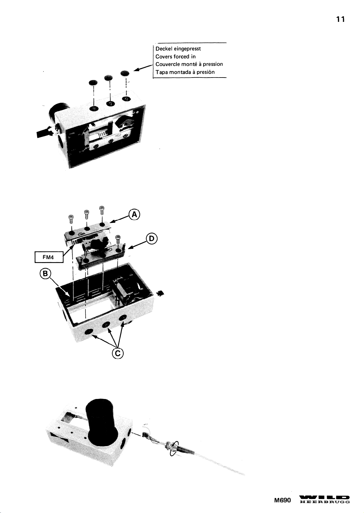
Montagehinweis:
-
Führung (A) gegen Anschlag (B) drücken und 3 Schrauben
anziehen.
- Mit 3 Schrauben (C) Führung (D) anstellen bis sich das
Rollenlager schwer verschieben lässt.
Assembly instructions:
-
Press guide bar (A) against stop (B) and tighten 3 screws
- Clamp guide bar (D) with 3 screw (C) until roller
bearings moves hard.
Page 19
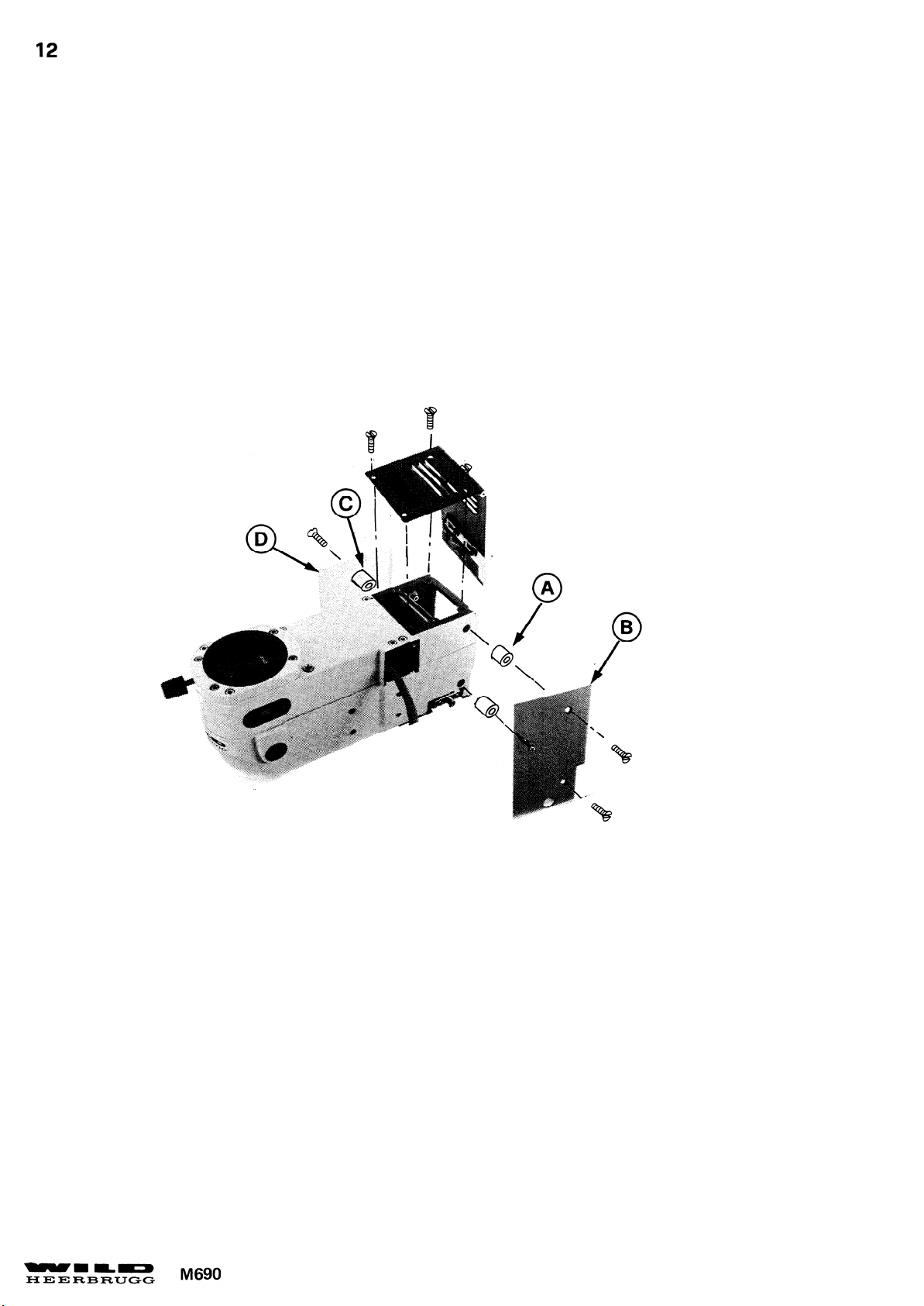
Hinweis:
Note:
Ober und Unterteil des Optikträgers können auch mit montiertem Triebkasten getrennt werden.
Upper and lower parts can also be separated without removing drive housing.
Montagehinweis:
Kurze Distanzbüchsen (A) bei Schutzblech (B) , lange Distanzbüchsen
Assembly instructions:
Mount short spacer bushes (A) to Protective cover
(B) and long spacer bushes (C) to protective cover (D) .
(C) bei Schutzblech (D) montieren.
Page 20
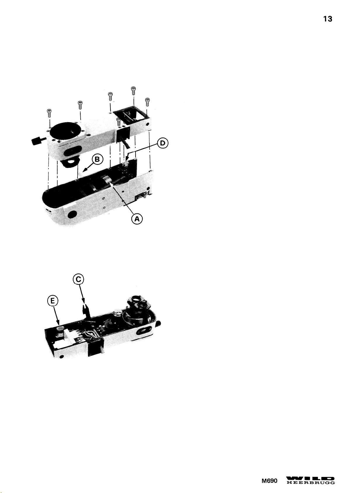
Kondensorschlitten (A) mit Trieb (B) ganz nach vorne
schieben und Oberteil nach oben abheben.
Montagehinweis:
-
Der Schlitz (C) muss in den Stift des Kondensorschlittens
eingreifen.
- Auf gute Verbindung der beiden Stecker (D) und (E)
achten.
Turn drive knob (B) to move condenser slide (A) com-
pletely forward and lift up upper part.
Assembly instructions:
- Slit (C) must engage in pin of condenser drive.
-
Ensure that plugs (D) and (E) are properly connected.
13
Page 21
14
2 Schrauben (A) demontieren und Achse (B) aus
Gehäuse stossen.
Montagehinweis:
- Schlitz (C) muss in Mitnehmerstift eingreifen.
- Durch lösen oder Anziehen der Mutter (D) Drehmoment
der Rutschkupplung auf 18,5 ± 1,5Ncm einstellen
(400gr
Remove 2 screws (A) and pull shaft (B) out of housing.
Assembly instructions:
- Slit (C) must engage in driving pin.
- Adjust torque of slide clutch to
slackening or tightening nut (D)
(400gr
- 470gr gemessen in Position (E) ).
18.5 ± 1,5Ncm by
- 470gr measured at point (E) ).
Page 22
15
Sicherungsscheibe (A) . Ritzel (B) und Schelle (C)
demontieren.
Remove locking washer (A) , pinion (B) and
screw with cable clip (C) .
Page 23
16
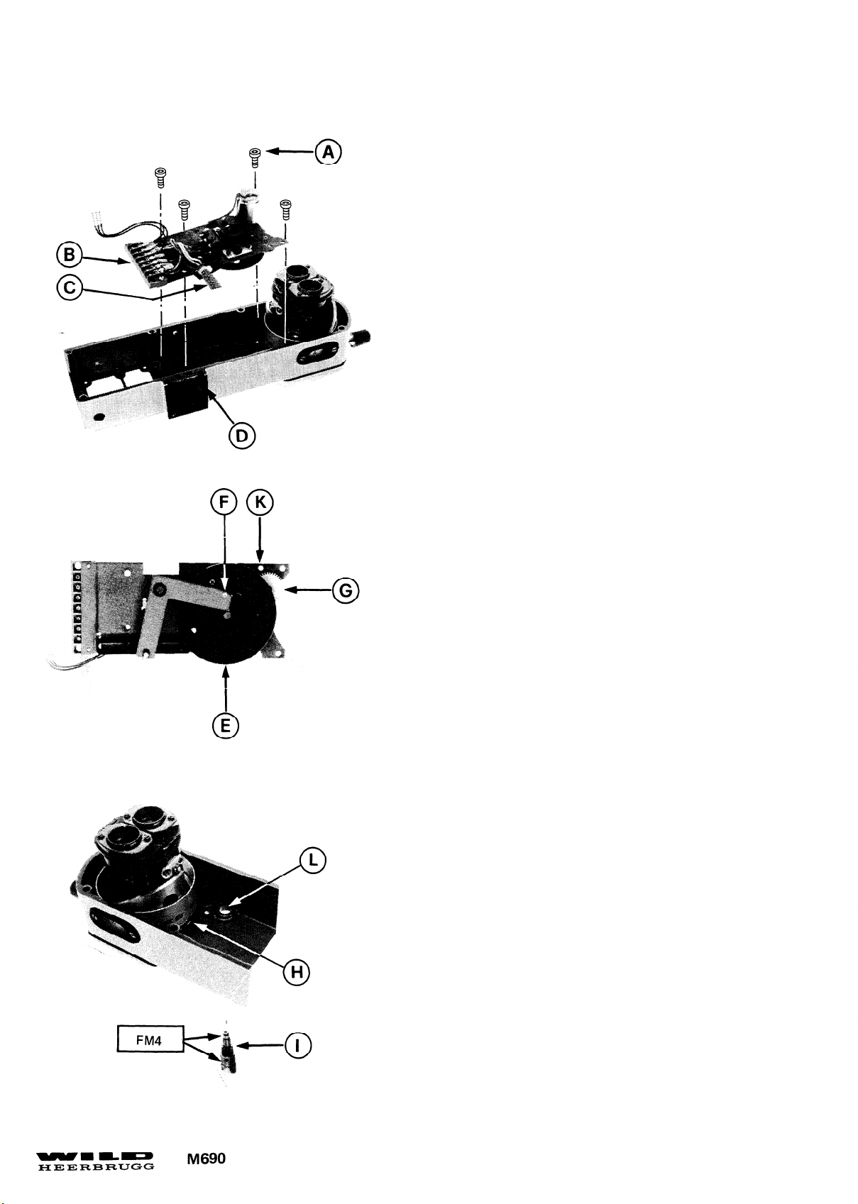
4 Schrauben (A) und Platine (B) demontieren. Kabel
(C) durch Schlitz (D) ziehen.
Zahneingriff zwischen Platine und Zoom einstellen.
- Die Mikroschalter und Endanschläge der Platine (B)
müssen vor der Montage korrekt eingestellt sein. siehe Seite 23
- Kurvenscheibe (E) im Gegenuhrzeigersinn (wenn Nockenscheiben oben sind) an inneren Anschlag (F) drehen.
- Zoom bei V=7x bis an Anschlag drehen.
-
Kabel einziehen und Platine (B) einlegen. Zahnräder (G)
und (H) nicht in Eingriff bringen.
- Zoom um einen Zahn vom Anschlag wegdrehen und
Zahnräder (G) und (H) in Eingriff bringen.
-
Ritzel (I) montieren. Durch Verschieben der Platine (B)
Ritzelführungen (K) und (L) ausrichten und Spiel zwischen
Zahnräder (G) und (H) einstellen.
Remove 4 screws (A) , plate (B) with zoom drive and
pull out cable (C) through slit (D)
Adjust meshing of gears between zoom drive and zoom.
- Adjust microswitches and stops correctly before
fitting plate (B) , see page 23
- Turn disk (E) with curved slot counterclockwise (when
cam disks facing up) to inner stop (F) .
- Turn zoom to stop position at 7x magnification.
-
Draw cable through slit and insert plate (B) with zoom drive.
Do not engage gearwheels (G) and (H) .
- Turn zoom 1 tooth back from stop position and engage
gearwheels (G) and (H) .
- Fit pinion
(K) and (L) and adjust clearance between gear wheels
(G) and (H)
(I) Shift plate (B) to align pinion bearings
.
.
Page 24
18
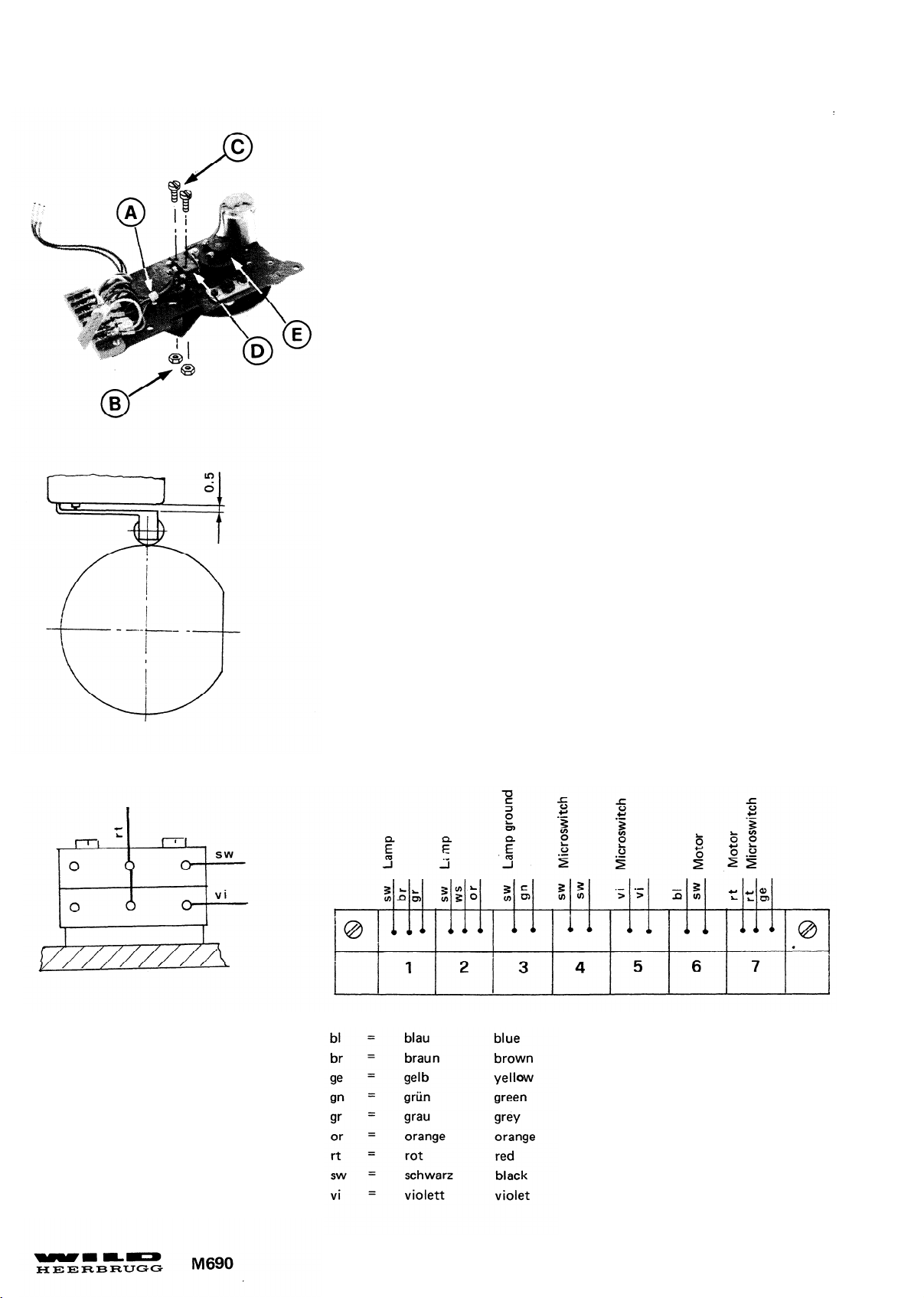
An Klemmleiste Anschlüsse 4,5 und 7,Kabelbinder (A) ,2 Muttern (B)
2 Schrauben (C) und 2 Mikroschalter (D) demontieren.
Montagehinweis:
Mikroschalter (D) schieben und Distanz zwischen Schaltfeder und
Gehäuse von 0,5mm einstellen. Schaltpunkte mit Nockenscheibe (E)
einstellen. Siehe Seite 24.
On terminal strip remove connections 4,5 and 7, cable tie (A) ,2
nuts (B) ,2 screws
Assembly instructions:
Displace microswitch (D) to adjust clearance between switch spring
and housing to 0,5mm The switch points of the microswitches are
adjusted by turning came disks (E) , see page 24.
(C) and 2 microswitches (D).
Page 25
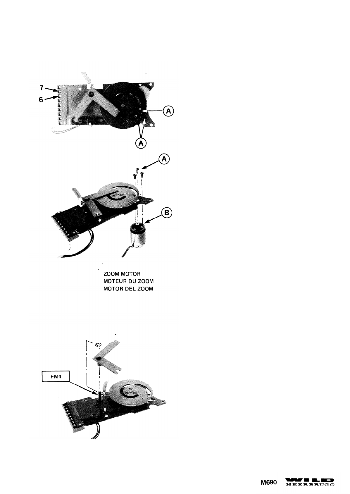
An Klemmleiste Anschlüsse 6 und 7 lösen. Durch Schlitz
und Bohrungen 3 Schrauben (A) und Motor (B) demontieren.
Unscrew connections 6 and 7 at terminal strip- Through
nut and holes unscrew 3 screws (A) and remove motor (B)
19
Page 26
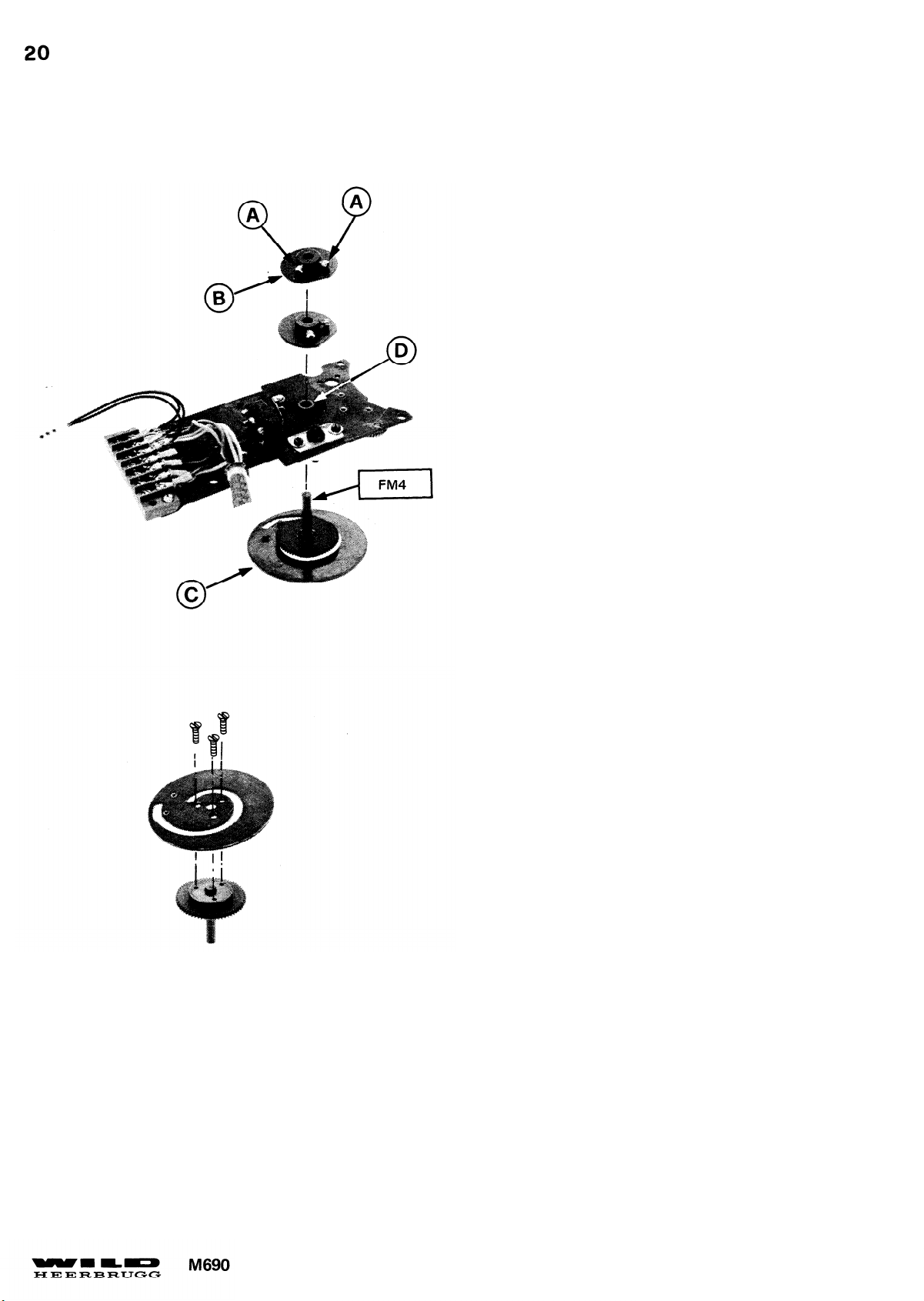
Schrauben (A) lösen, Nockenscheiben (B) und
Kurvenscheibe (C) demontieren.
Montagehinweis:
-
Durch Verschieben von Flansch (D) Zahneingriff
einstellen.
- Nockenscheibe (B) einstellen siehe Seite.24.
Slacken screws (A) and remove cam disks (B)
and curve disk (C) .
Assembly instructions:
- Adjust meshing of gears by displacing flange (D).
- To adjust cam disks (B) see page 24.
Page 27
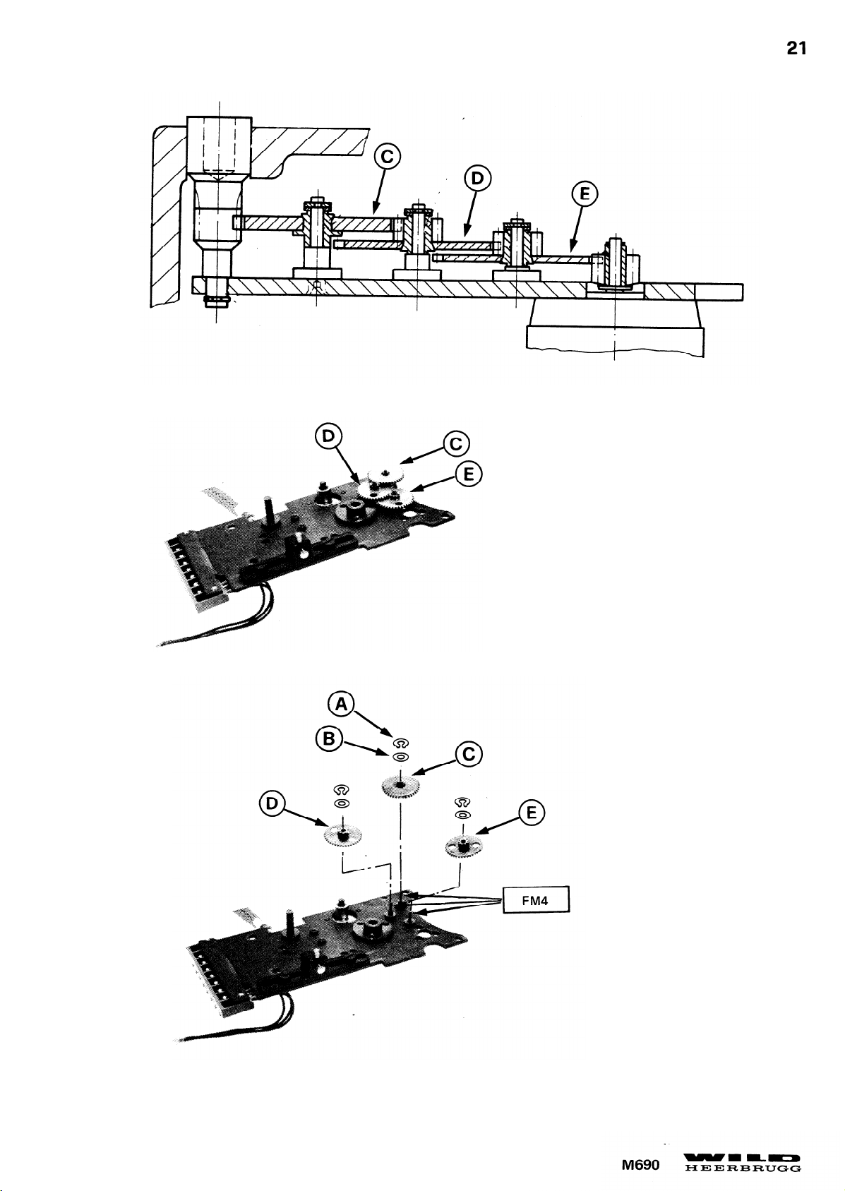
21
Page 28
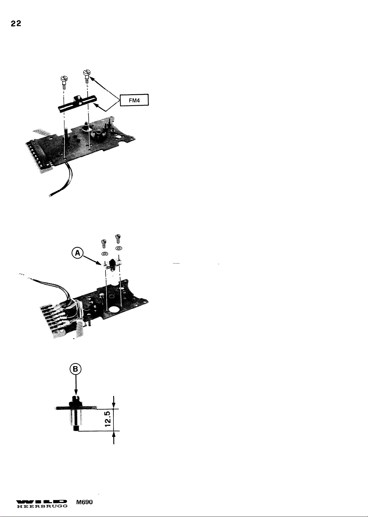
Montagehinweis:
-
Flansch (A) ganz nach hinten (Richtung Klemmleiste)
schieben.
-
Zapfenschraube (B) auf 12,5mm einstellen. Siehe Foto.
Assembly instructions:
- Push flange (A) completly back (towards terminal
strip).
- Adjust length of trunnion screw (B) to 12,5mm
(see illustration).
Page 29
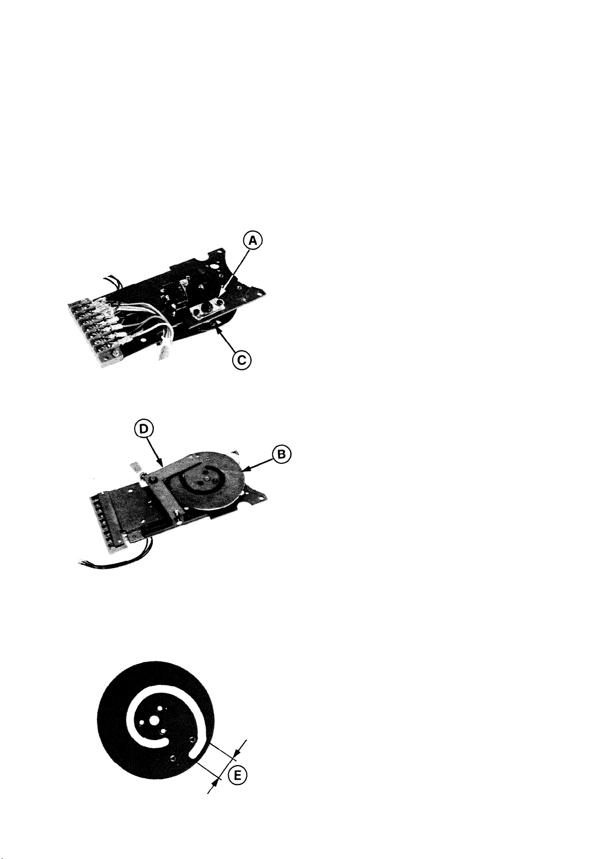
JUSTIERUNG DER PLATINE MIT ZOOMANTRIEB
ADJUSTMENT OF PLATE WITH ZOOM DRIVE
1. Anschlag (A) einstellen.
-
Anschlag (A) ganz nach hinten gegen Klemmleiste schieben.
- Wenn die Kurvenscheibe (B) am Anschlag (A) anschlägt,
muss das Kugellager (C) des Hebels (D) innerhalb des
zentrischen Bereiches (E) der Kurvenscheibe liegen.
23
Adjust stop (A) .
-
Push stop (A) completely back against terminal strip.
- When curved disk (B) is against stop (A) ball bearing (C)
must be within centric range (E) .
Page 30
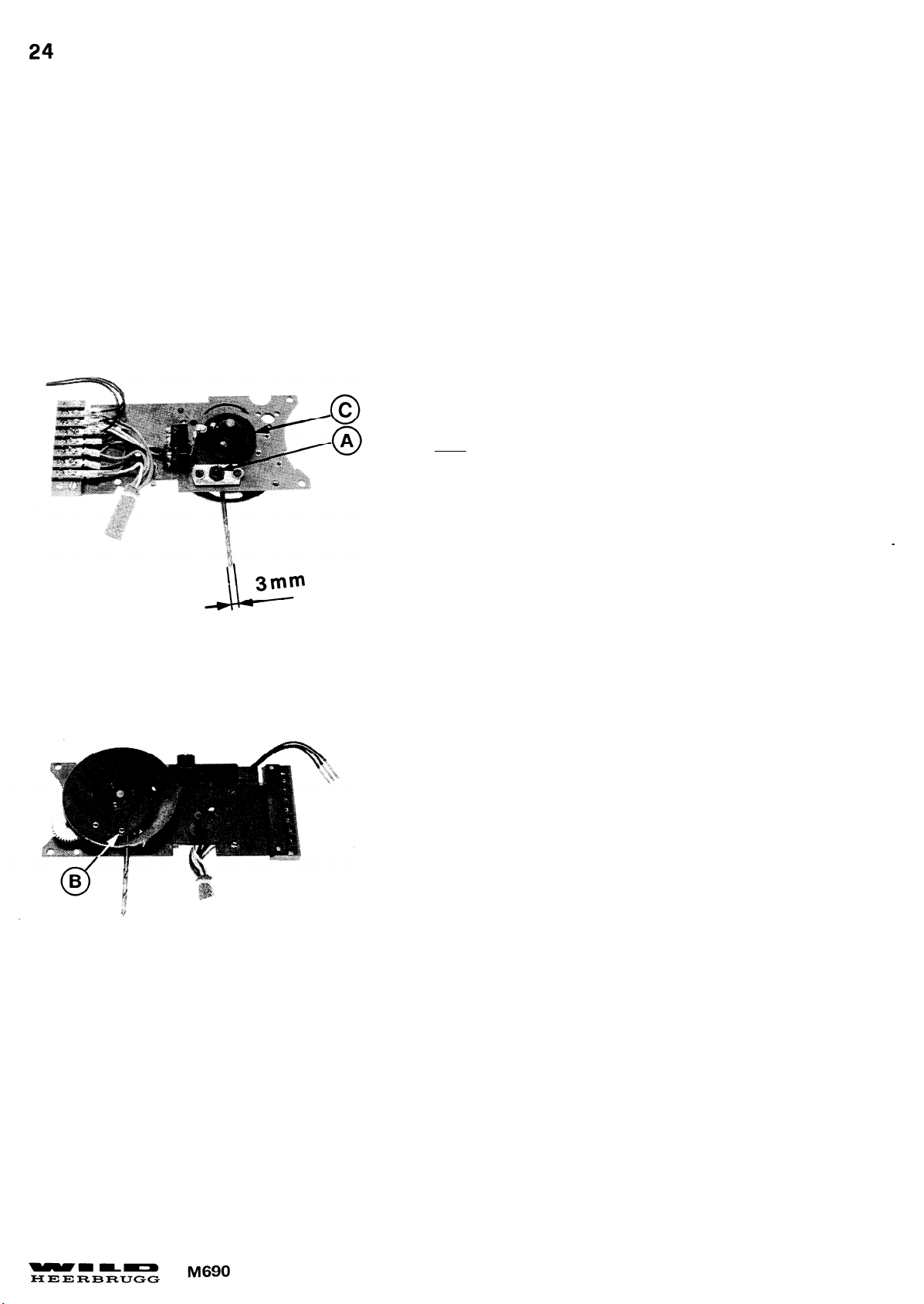
2. Schaltpunkt unterer Mikroschalter.
- Kurvenscheibe im Uhrzeigersinn (Nockenscheibe oben)
gegen Anschlag drehen.
-
Bohrer ø3mm zwischen Anschlag (A) der Platine und
Anschlag (B) der Kurvenscheibe legen.
- Kurvenscheibe gegen Bohrer drücken und untere Nocken-
scheibe (C) drehen bis Mikroschalter schaltet.
-,Durch Verschieben der Nockenscheibe axial Spiel einstellen
max. 0,05mm
2. Adjust switch point of lower microswitch-
- Turn curved disk clockwise (cam disks facing up) against
stop.
- Plate 3mm dia. drill between stop (A) of plate and stop (B)
of curved disk.
- Turn curved disk to clamp drill between stops and turn lower
cam disk (C) until lower microswitch switches.
- Displace cam disk verticaly to adjust axial play to 0,05mm
max.
Page 31
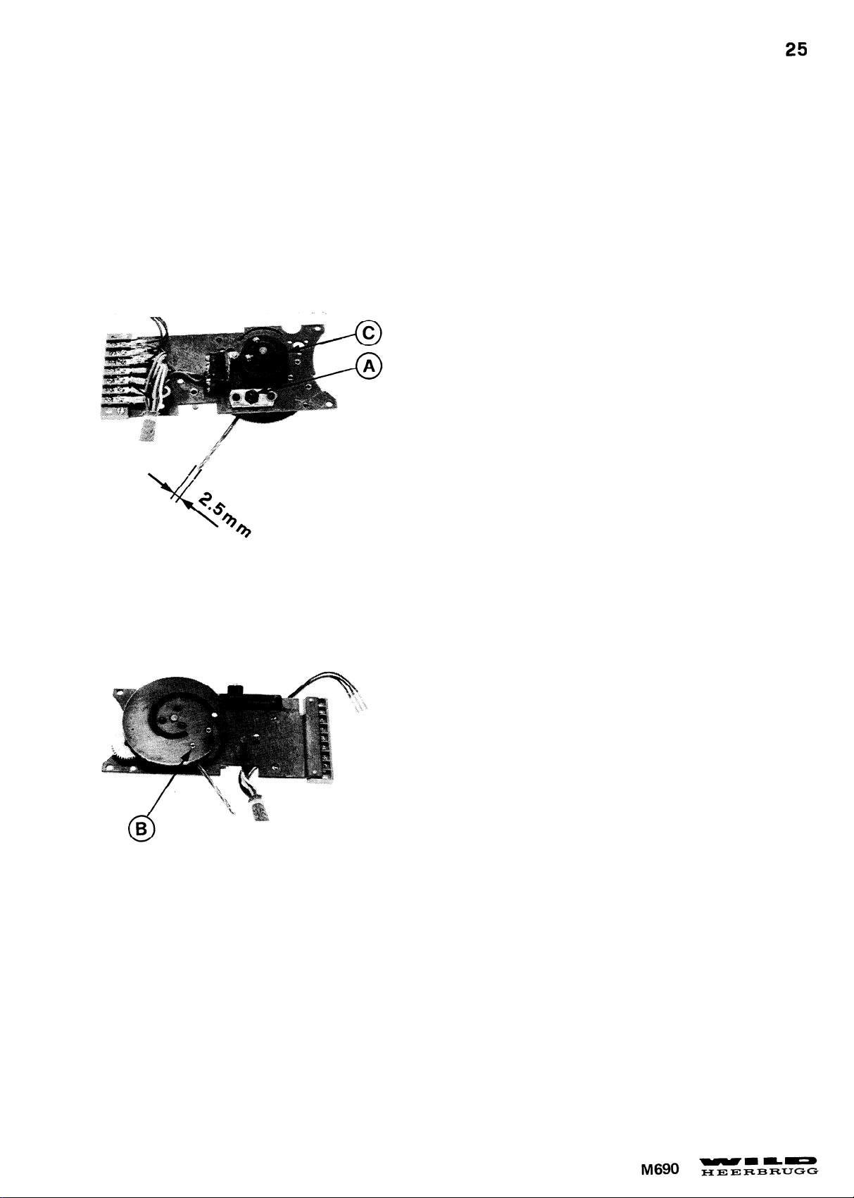
3. Schaltpunkt oberer Mikroschalter
-
Kurvenscheibe im Gegenuhrzeigersinn (Nockenscheibe oben)
gegen Anschlag drehen.
-
Bohrer ø2,5mm zwischen Anschlag (A) der Platine und Anschlag
(B) der Nockenscheibe legen.
-
Kurvenscheibe gegen Bohrer drücken und ober Nockenscheibe (C)
drehen bis der Mikroschalter schaltet.
---
3. Adjust switch point of upper microswitch.
- Turn curved disk counterclockwise (cam disks facing up)
against stop.
- Plate 2,5mm dia. drill between stop (A) of plate and stop
(B) of curved disk
- Turn curved disk to clamp drill between stops and turn upper
cam disk (C) until microswitch switches.
Page 32
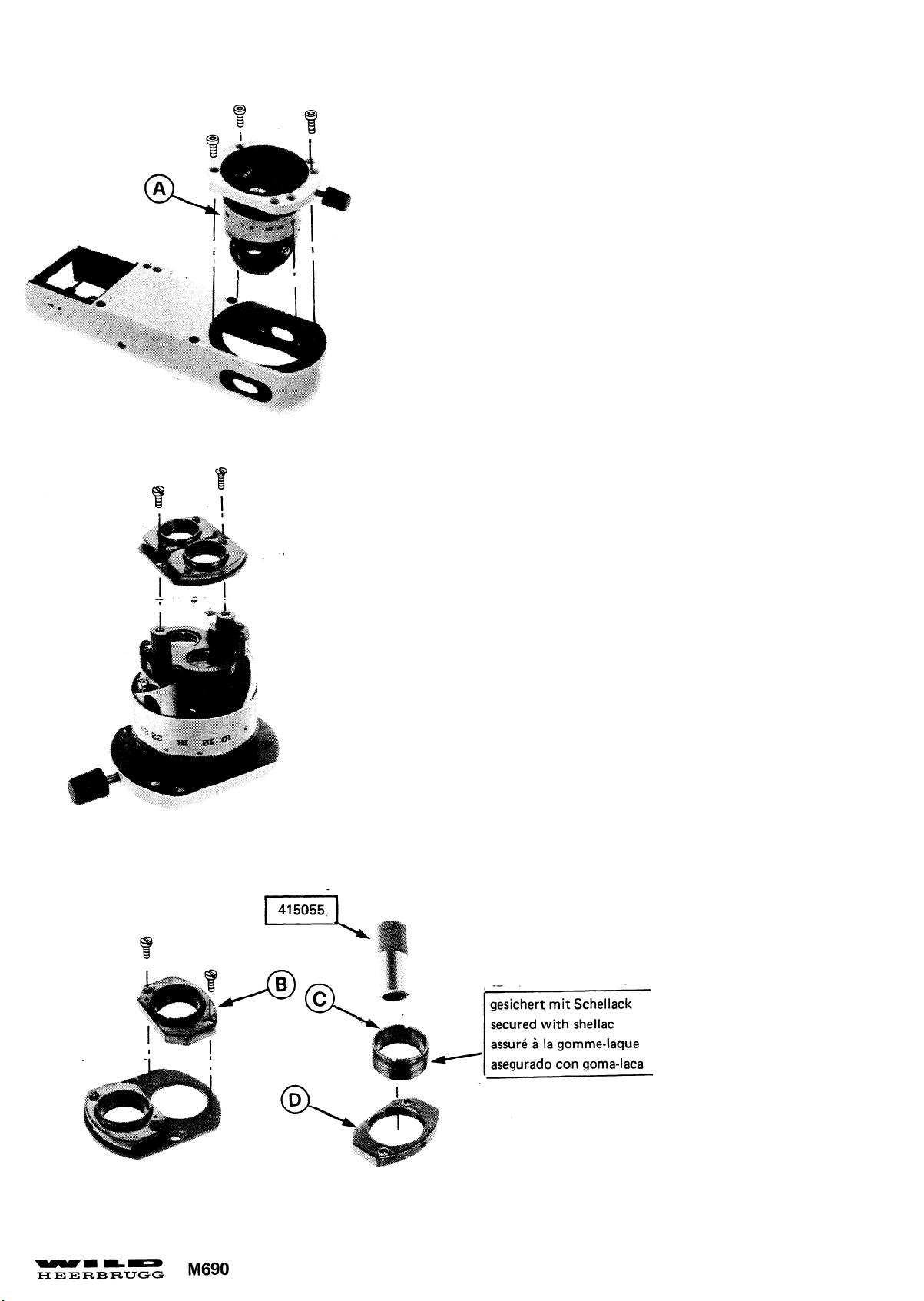
26
Montagehinweis:
-
Bei Demontage der Zoomeinheit (A) bei montierter
Platine muss der Zahnradeingriff eingestellt werden.
Siehe Seite 16.
- Justierung der Objektive (B) und (C) siehe Justieranleitung
-
Die Auflagefläche der Platte (D) ist mit einem Körnerpunkt gezeichnet
Assembly instructions:
- Adjust meshing of gears when removing the zoom unit (A)
without removing the plate with zoom drive, see page 16.
- To adjust objectives (B) and (C) see adjustment instructions.
- The screwon face of plate (D) is marked with a punch
mark.
Page 33
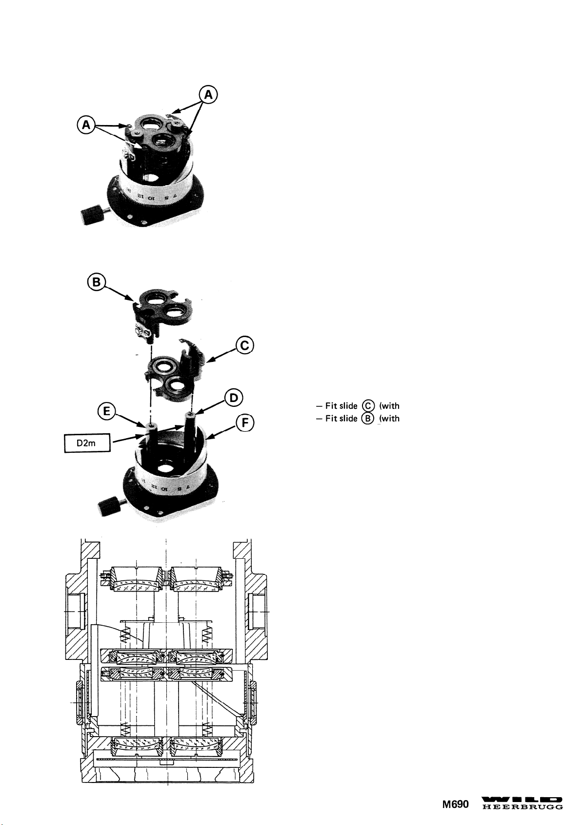
27
4 Federn (A) aushängen
Unhook 4 springs (A) .
Montagehinweis:
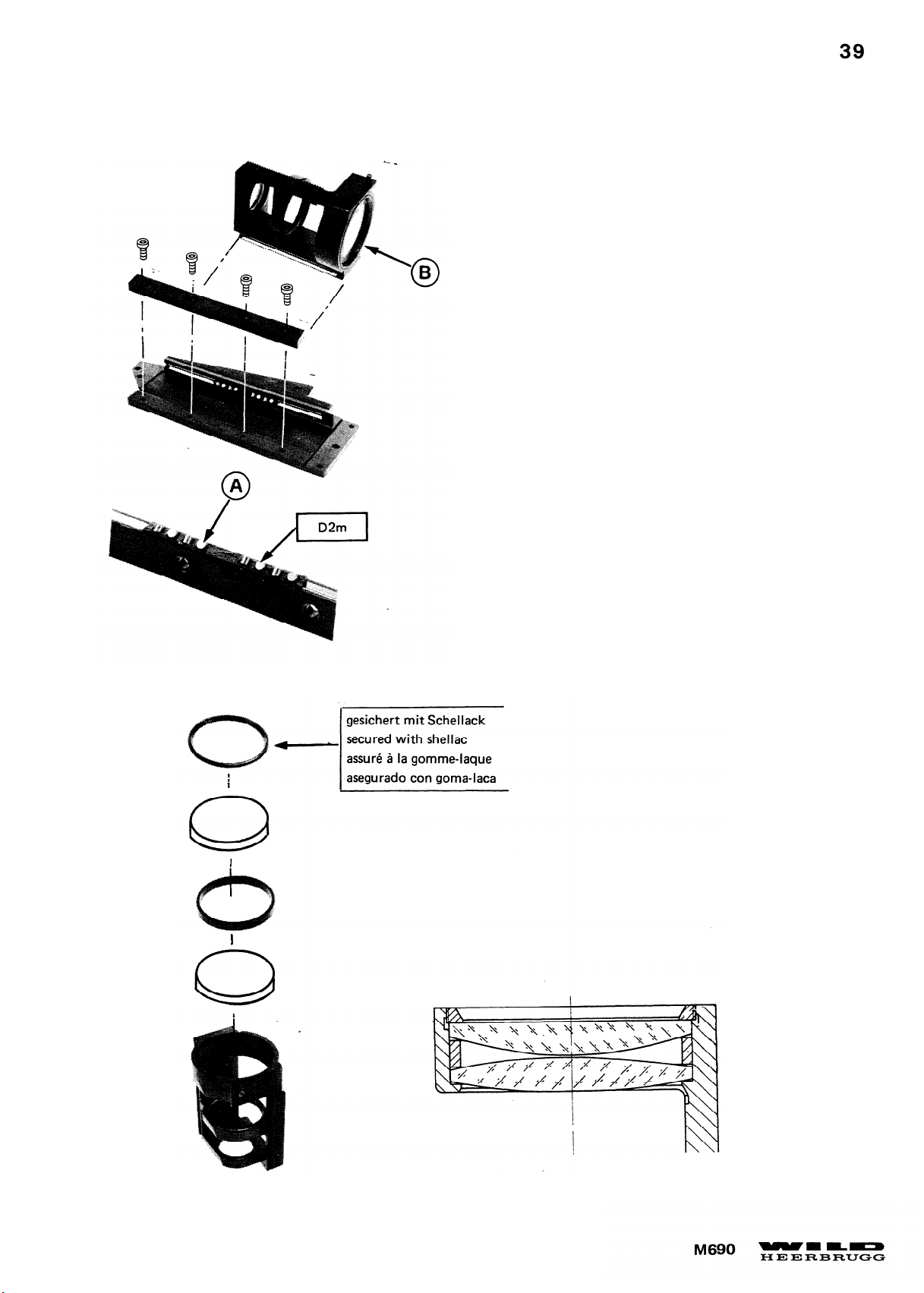
- Schieber (C) (kleine Objektive) auf Säule (D) montieren.
- Schieber (B) (grosse Objektive) auf Säule (E) montieren.
-
Auf korrekte Position von Kurvenkörper (F) achten.
Siehe Seite. 29.
Assembly instructions:
small objectives) on guide rod (D)
large objectives) on guide rod (E)
- Cam sleeve (F) must be in correct position (see page 29.)
Page 34
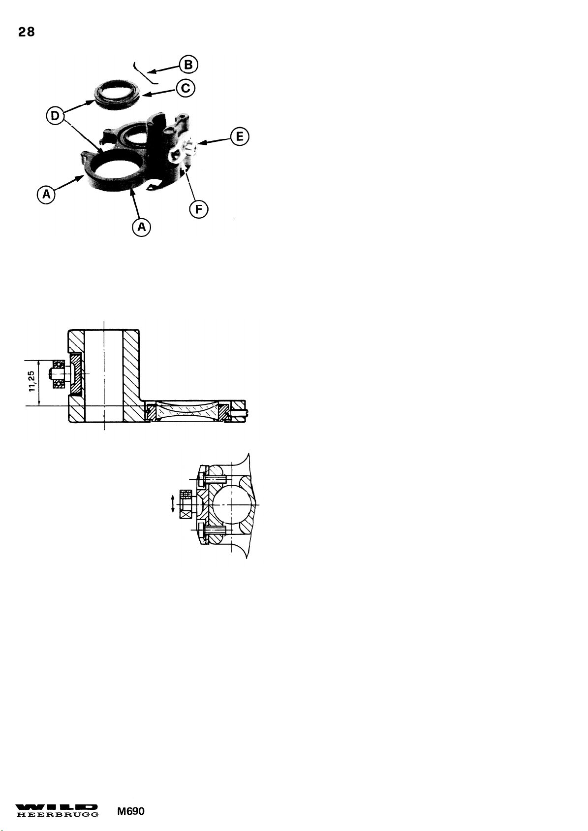
Flansch Position Höhe
Vertical flange position
Montagehinweis:
Die Feder (B) muss gegenüber den 2 Schrauben (A)
montiert sein und in den Rillen (D) liegen. Justierung
siehe Justieranleitung.
Assembly instruction:
Spring (B) must be opposite the two screws (A) and
must sit securely in grooves (D)
. To adjust objectives,
see adjustment instructions.
Distanz für eine Linsendicke von 3,1mm.
Distance for lens thickness of 3.1 mm.
Flansch Position Seite
Lateral flange position
-
Das Kugellager (E) ist mit Loctite auf die Achse geklebt.
-
Der Flansch (F) sollte nicht demontiert werden. (Fabrikjustierung mit Vorrichtung.)
-
Durch eine falsche Position des Flansches (F) wird das Bild in der mittleren Vergrösserung unscharf.
-
The ball-bearing (E) is cemented with Loctite to shaft.
Genau Mitte Säulenbohrung
Exact centre of guide-rod bore
- Flange (F) should not be removed (works adjustment with special device.)
-
Unsharpness will occur at mean magnification through wrong position of flange (F) .
Page 35
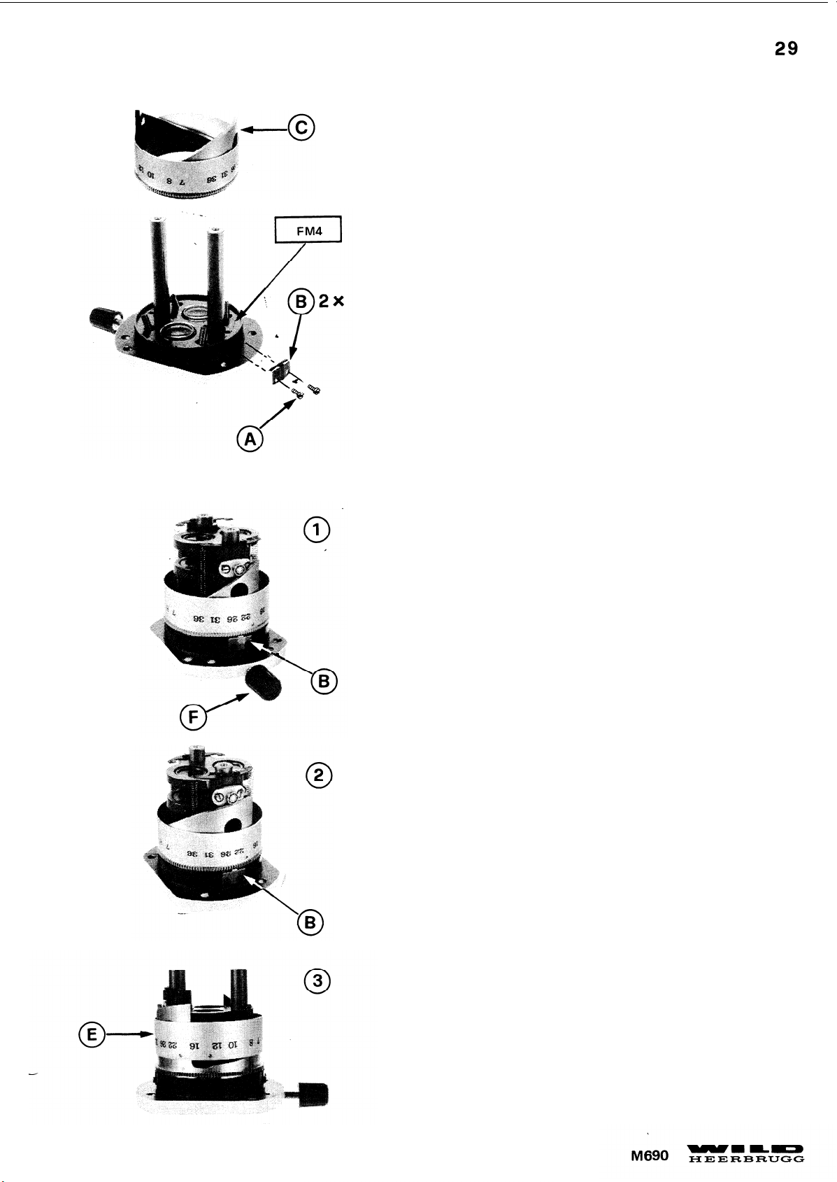
Montagehinweis für Bremsfedern (B)
:
- Schieber montieren und Federn einhängen.
-
Bremsfedern (B) nach unten drücken bis der Zoom in jeder Stellung
stehen bleibt.
Montagehinweis für Kurvenkörper (C) .
Kurvenkörper (C) mit steiler Kurve bei Klemmschraube (F) (siehe
Foto (1) ) und flacher Kurve nach hinten (siehe Foto (2) ) montieren
Montagehinweis für Skalaring (E)
:
Gravur zu Kurvenkörper ausrichten (siehe Foto (3) ).
Assembly instructions for brake springs (B)
:
- Fit both slides and attach springs.
-
Adjust braking torque by pressing brake springs (B) down until
zoom is held in any Position.
Assembly instructions for came sleeve (C)
:
Fit cam sleeve (C) with steep curve towards clamping screw (F)
(see illustration (1) ) and flat curve facing back (see illustration (2) ).
Assembly instructions for scale ring:
Align graduation to cam sleeve (see illustration (3) )
Page 36
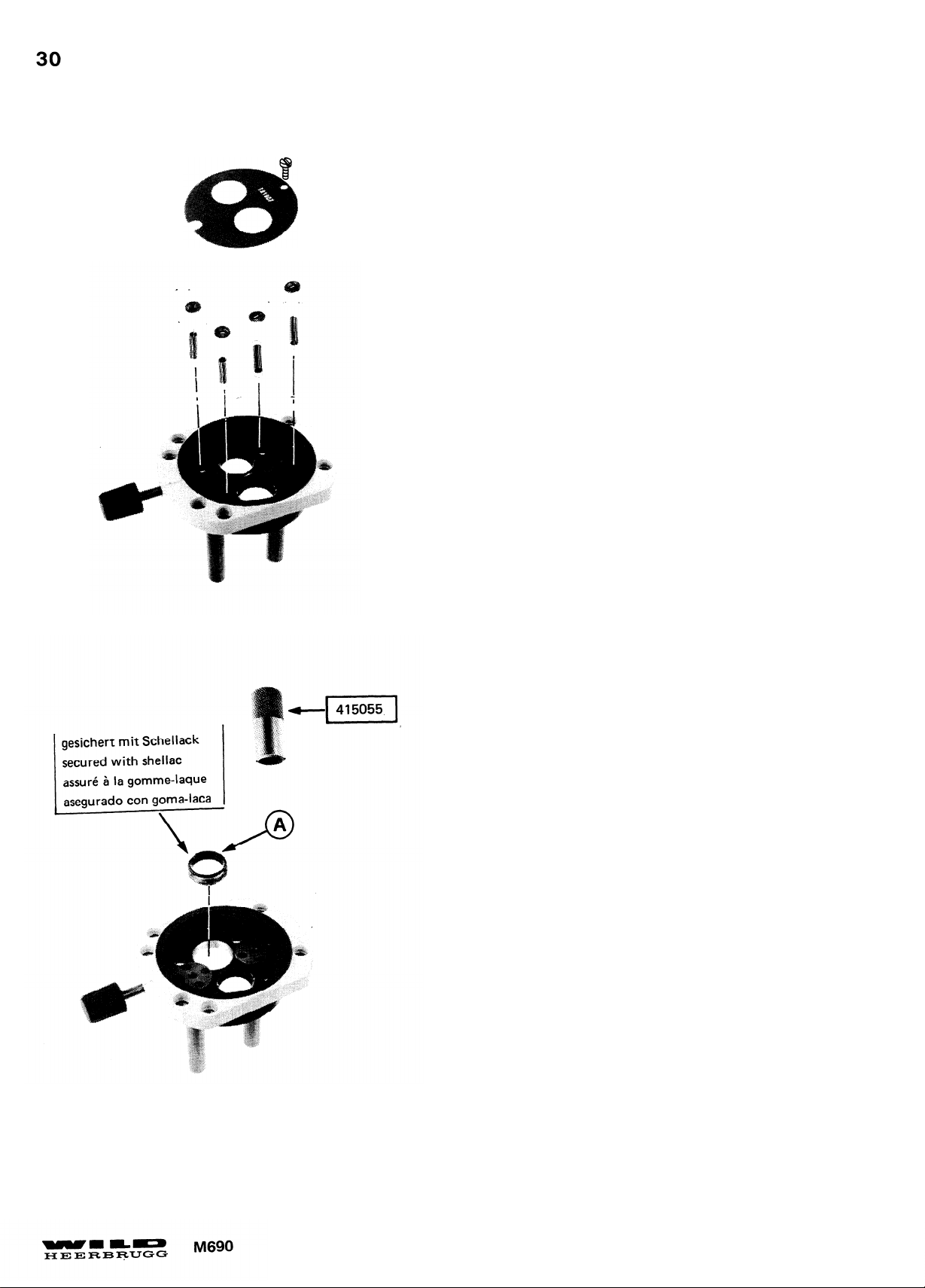
Justierung Objektiv (A) siehe Seite 34.
To adjust objective (A) see page 34 .
Page 37
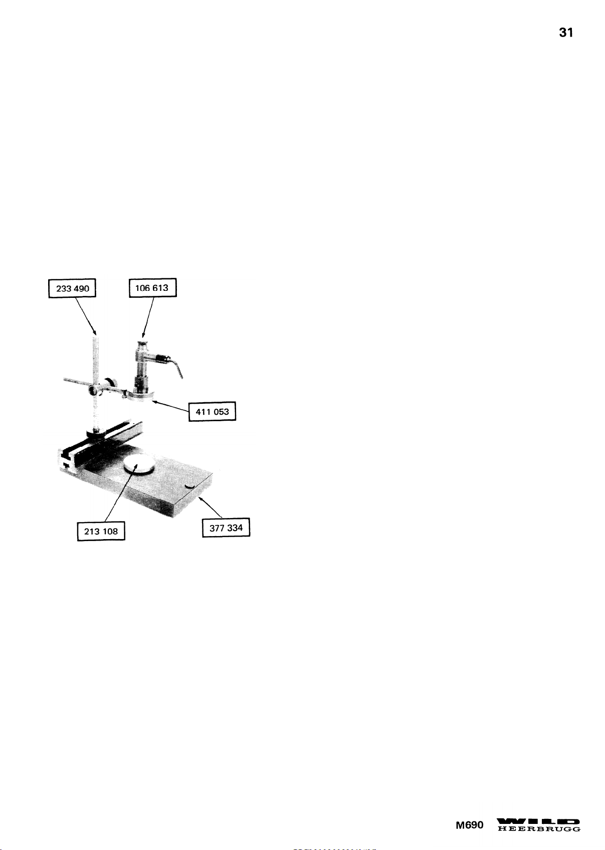
JUSTIERANLEITUNG
ADJUSTMENT INSTRUCTIONS
Zoom justieren:
- Autokollimator mit Halter an Messuhrständer
montieren. Messuhrständer und Spiegel auf
Planplatte stellen.
- Autokollimator ausrichten, bis das vom Spiegel
reflektierte Leuchtkreuz zur Strichplatte genau
zentriert ist.
Adjusting zoom
- Fit autocollimator with holder to stand for dial
gauge. Plate stand for dial gauge and mirror on
plane-parallel plate.
- Centre luminous cross reflected by mirror by
aligning autocollimator.
Page 38
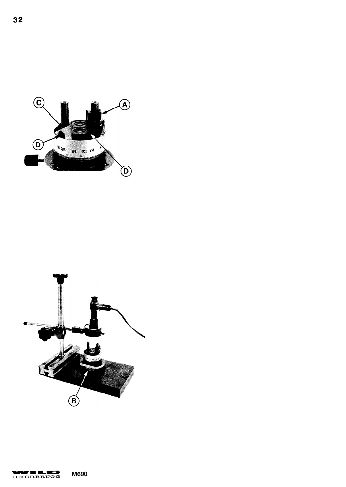
JUSTIERANLEITUNG
ADJUSTMENT INSTRUCTIONS
Unterer Schieber zentrieren
- Schieber (A) montieren;
- Zoom auf Spiegel (B) stellen.
-
Kurvenkörper (C) drehen, bis das Leuchtkreuz scharf
abgebildet ist.
-
Leuchtkreuz mit 2 Schrauben (D) genau zur Strichplatte zentrieren.
Centering lower slide
-
Fit slide (A) .
- Plate zoom on mirror (B) .
-
Focus image of luminous corss by turning cam sleeve (C)
- Centre Iuminous cross exactly on reticle by 2 screws (D)
Page 39
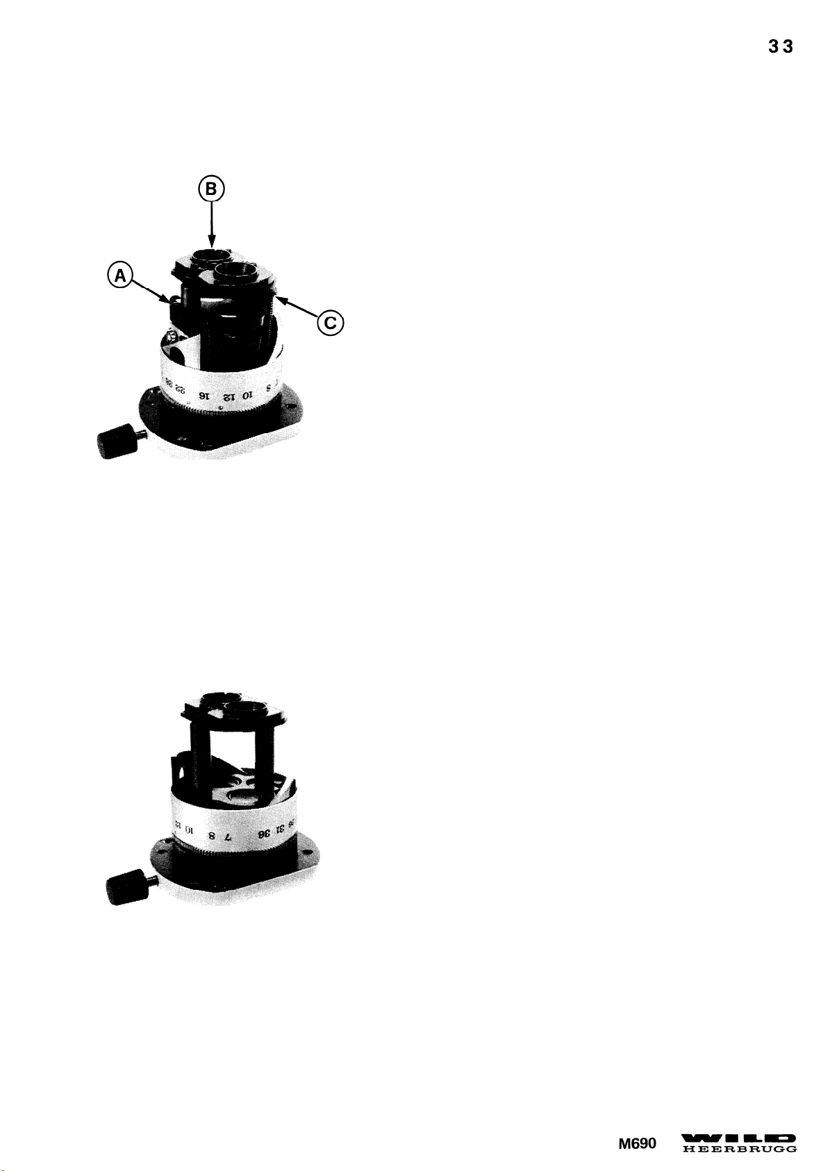
JUSTIERANLEITUNG
ADJUSTMENT INSTRUCTIONS
Bildhöhe justieren:
- Oberer Schieber (A) , Objektive (B) montieren Federn (C)
einhängen.
- V= 36x einstellen (Schieber unten
-
Durch Verdrehen der Objektive (B) das Leuchtkreuz in der
Strichplattenebene des Autokollimators scharf abbilden.
Adjust image height:
-
Fit upper slide (A) and objective (B) attach springs (C) .
- Set to 36x magnification (both slides down)
- Focus image of luminous cross in reticle plane of autocollimator
by turning objective (B) .
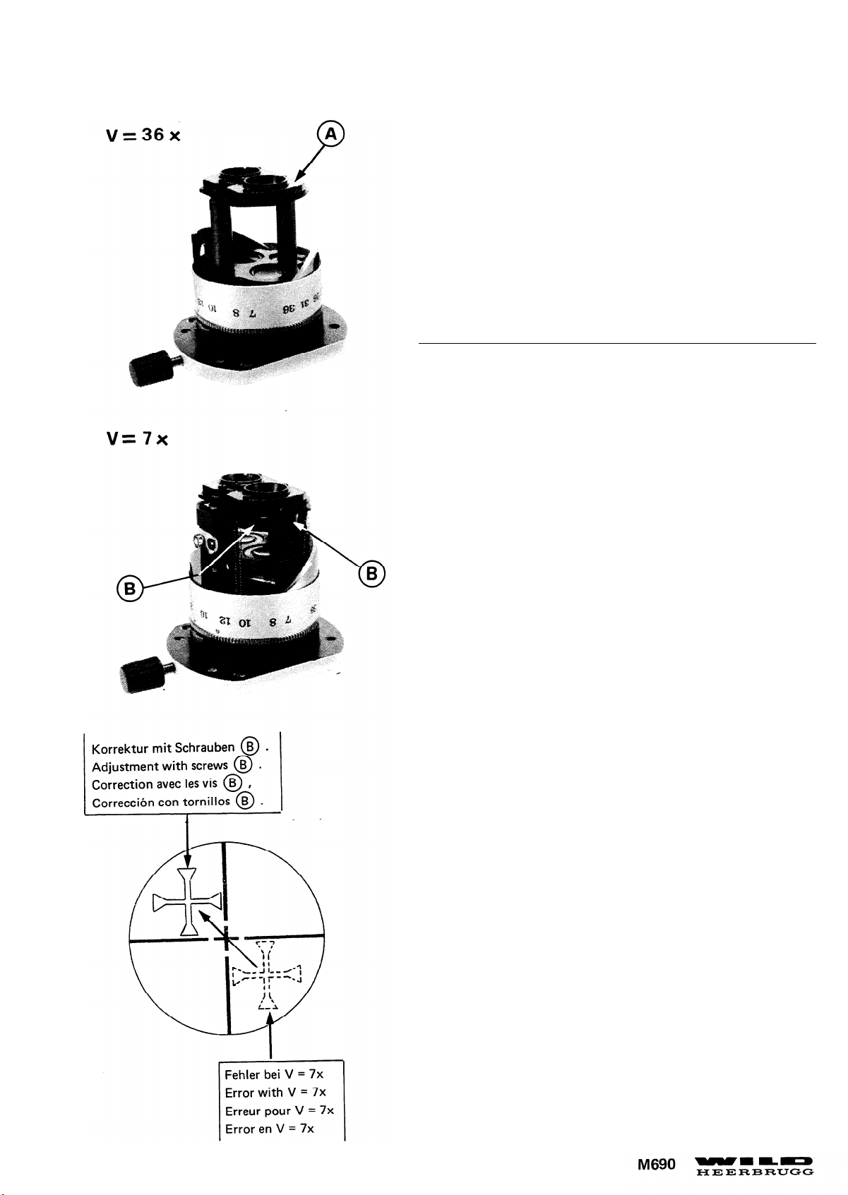
V=36x
Page 40
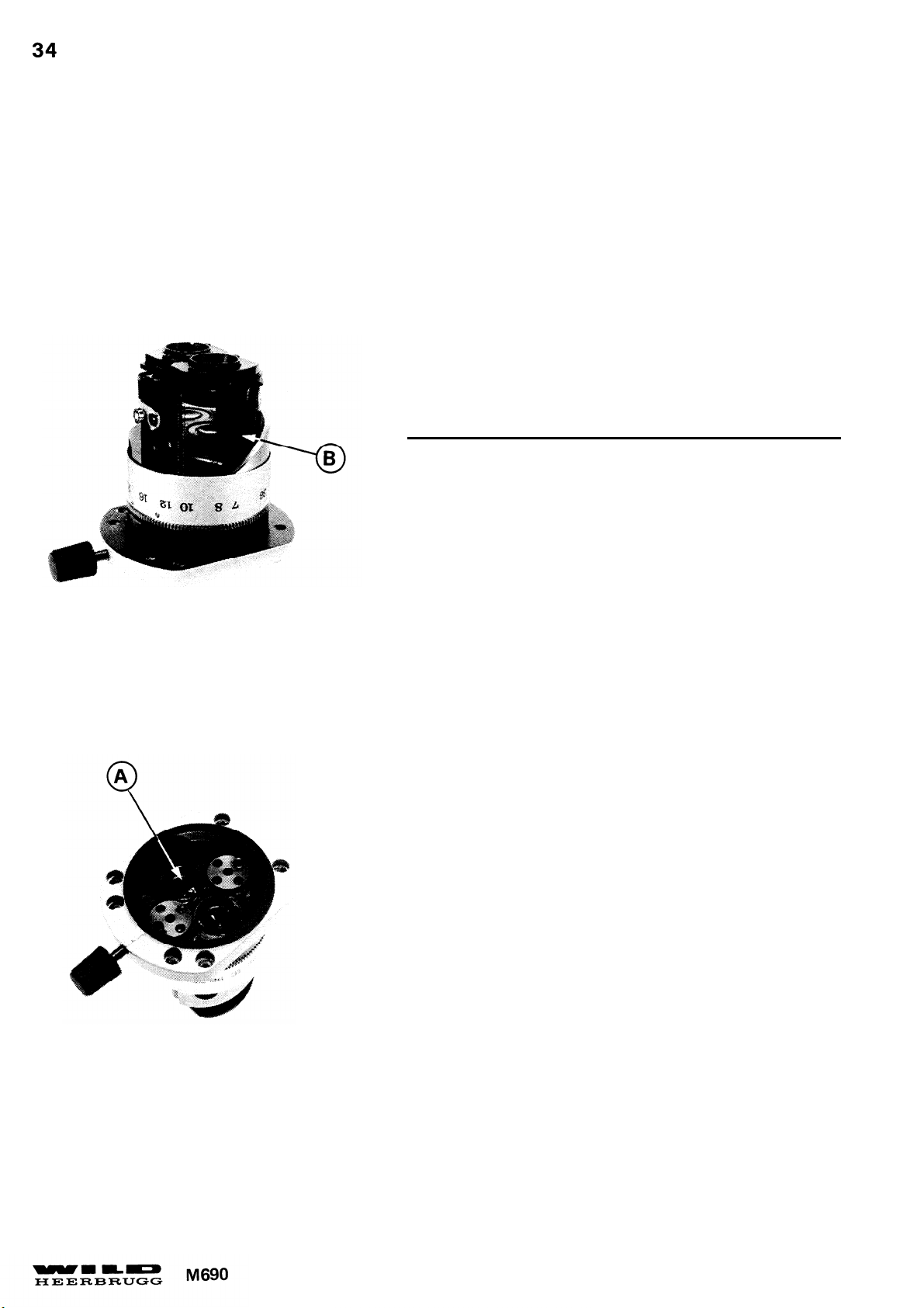
V = 7x
JUSTIERANLEITUNG
ADJUSTMENT INSTRUCTIONS
- V = 7x einstellen (Schieber oben)
-
Durch Verdrehen der Objektive (A) das Leuchtkreuz in der
Strichplattenebene scharf abbilden.
Bild zu hoch = Objektiv nach unten
Achtung:
Werden die Objektive (A) verstellt, muss die Zentrierung vom
unteren Schieber (B) wiederholt werden. Siehe Seite 32.
Toleranz:
Die Leuchtkreuze beider Strahlengänge müssen über den ganzen
Zoombereich scharf abgebildet sein. Bei Fehler in der mittleren
Vergrösserung siehe Seite 28.
- Set to 7x magnification (both slides up).
- Focus image of luminous cross in reticle plane by
turning objective (A)..
Note:
If objectives (A) have been moved, repeat centring of
lower slide (B) , see page 32.
Tolerance:
The luminous cross must be in sharp focus over
the entire zoom range in the left and right optical
paths. In case of Unsharpness at mean magnification,
see page 28.
Page 41
JUSTIERANLEITUNG
ADJUSTMENT INSTRUCTIONS
35
Zoom zentrieren:
- V = 36x einstellen (Schieber unten)
- Durch Verschieben der Objektivfassung (A) Leuchtkreuz
zur Strichplatte zentrieren.
- V = 7x einstellen (Schieber oben)
- Mit 2 Schrauben (B) Leuchtkreuz symmetrisch gegenüberstellen
- V = 36x einstellen und Leuchtkreuz mit Objektivfassung (A)
genau zur Strichplatte zentrieren.
Toleranz:
Die Leuchtkreuze beiden Strahlengänge müssen sich im ganzen
Zoombereich decken und die Strichplatte mindestens berühren.
Centring zoom:
- Set to 36x magnification (both slides down)
- By displacing objective mount (A) , centre luminous cross
on reticle.
- Set to 7x magnification (both slides up).
- Move luminous cross symmetrically opposite by two screws
(B).
- Set to 36x magnification and centre luminous cross exactly
on reticle by displacing objective mount (A) .
Tolerance:
The luminous cross must overlap by at least half its extent in
the left and right optical paths, over the entire zoom range, and
must at least touch the reticle.
Page 42
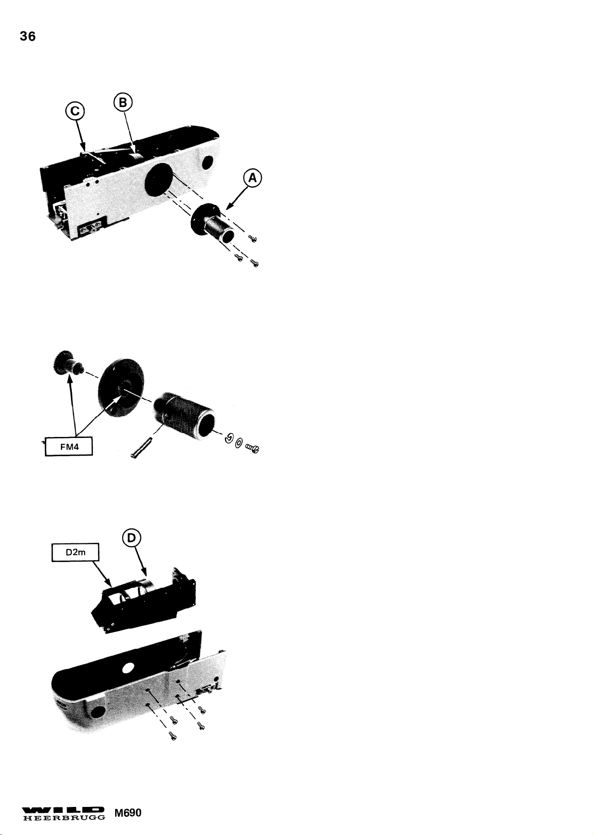
Montagehinweis:
- Kollektor mit Schieber (D) nach unten gegen
Anschlag drücken.
- Handantrieb (A) im Gegenuhrzeigersinn bis an
Anschlag drehen.
- Schlitten (B) gegen Kollektor (C) bis an Anschlag
schieben. Um einen Zahn zurück und Handantrieb
einrasten.
Assembly instructions:
- Push down collector assembly (D) to stop.
- Turn manual drive (A) counterclockwise to stop.
-
Push slide (B) towards collector to stop. Move
slide (B) by 1 tooth back from stop position and
engage maual drive.
Page 43
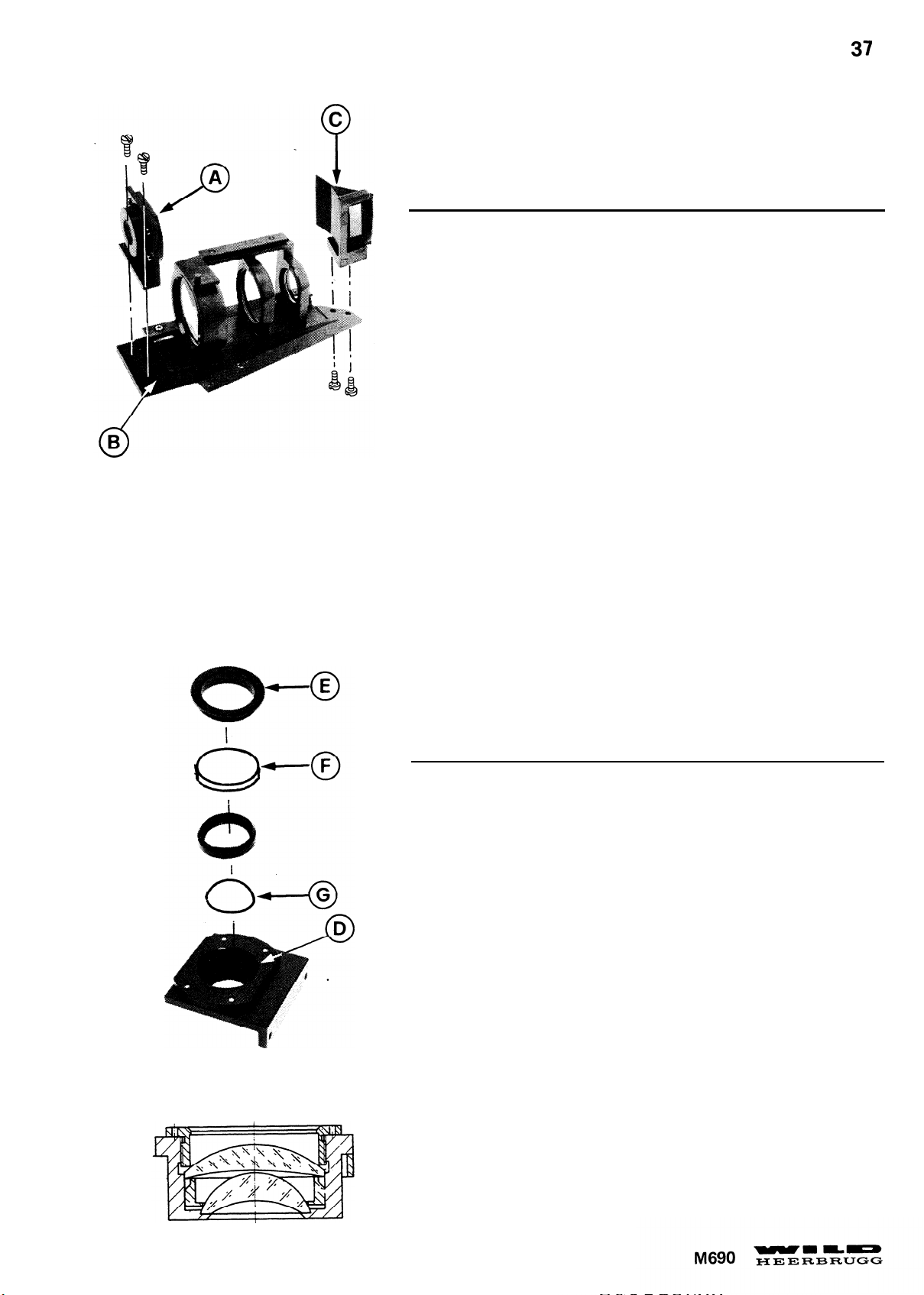
Montagehinweis:
-
Kollektor (A) gegen Anschlag (B) drücken und seitlich in Schraubenlöchern ausgemittelt montieren.
- Justierung Prisma (C) siehe Seite 38 .
Assembly instructions:
-
Push collector (A) to stop (B) and fit laterally symmetrical to screw
holes.
- To adjust prism (C) see page 38.
Achtung:
Fassung (D) nicht demontieren.
Montagehinweis:
Gewindering (E) anziehen und wieder 1/8 Umdrehung lösen. Linsen (F)
und (G) müssen lose montiert sein.
Attention:
Do not remove mount (D) .
Assembly instructions:
Tighten threaded ring (E) and slacken again by 1/8 turn. Lenses (F)
and (G) must be loose in mount.
Page 44
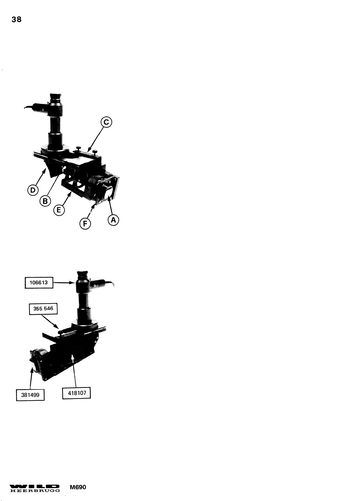
Montagehinweis:
-Spiegel (A) mit Fett an Kollektorfassung kleben.
-
Platte (B) mit Vorrichtung (C) an Schieber klemmen. Autokollimator
über Prisma (D) stellen.
- Schieber (E) gegen Kollektor (F) schieben bis runder Leuchtfleck
scharf abgebildet ist.
- Autokollimator schieben bis runder Leuchtfleck nicht mehr beschnitten
ist.
-
Durch Kippen von Prisma (D) Leuchtfleck zu Kollimatorstrichplatte
zentrieren.
Assembly instructions:
- Use grease to make mirror (A) adhere to collector.
-
Clamp plate (B) with jig (C) to slide and plate autocollimator above
prism (D) .
- Shift slide (E) towards collector until circular light spot is sharply
focused.
- Displace autocollimator until there is no cutoff to light spot.
-
Tilt prism (D) to centre light spot on reticle of. autocollimator.
Page 45
Montagehinweis:
-
Rollen (A) wechselseitig einlegen.
- Schlitten (B) spielfrei montieren.
Assembly instructions:
- Insert rollers (A) alternately.
- Fit slide (B) without slack
Page 46
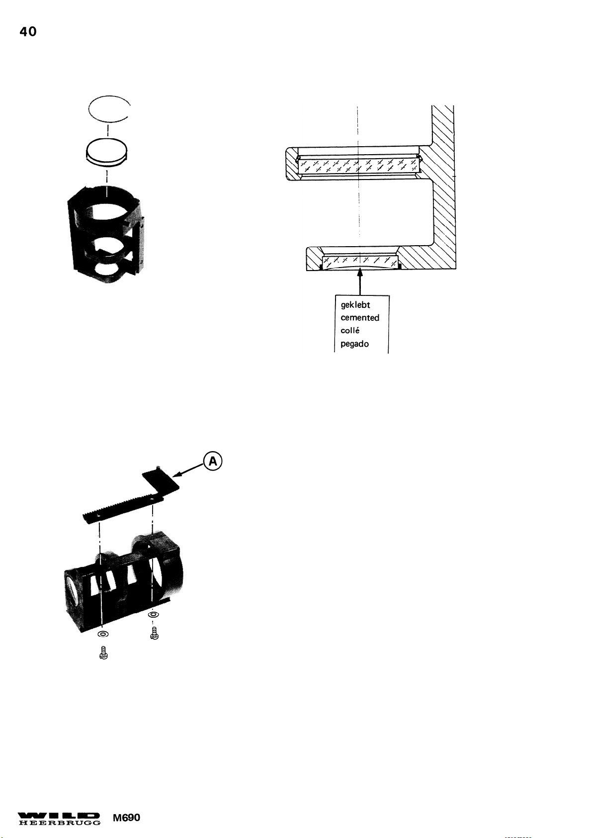
Montagehinweis:
Zahnstange (A) im Instrument ausrichten.
Assembly instructions:
Align rack (A) in instrument.
Page 47
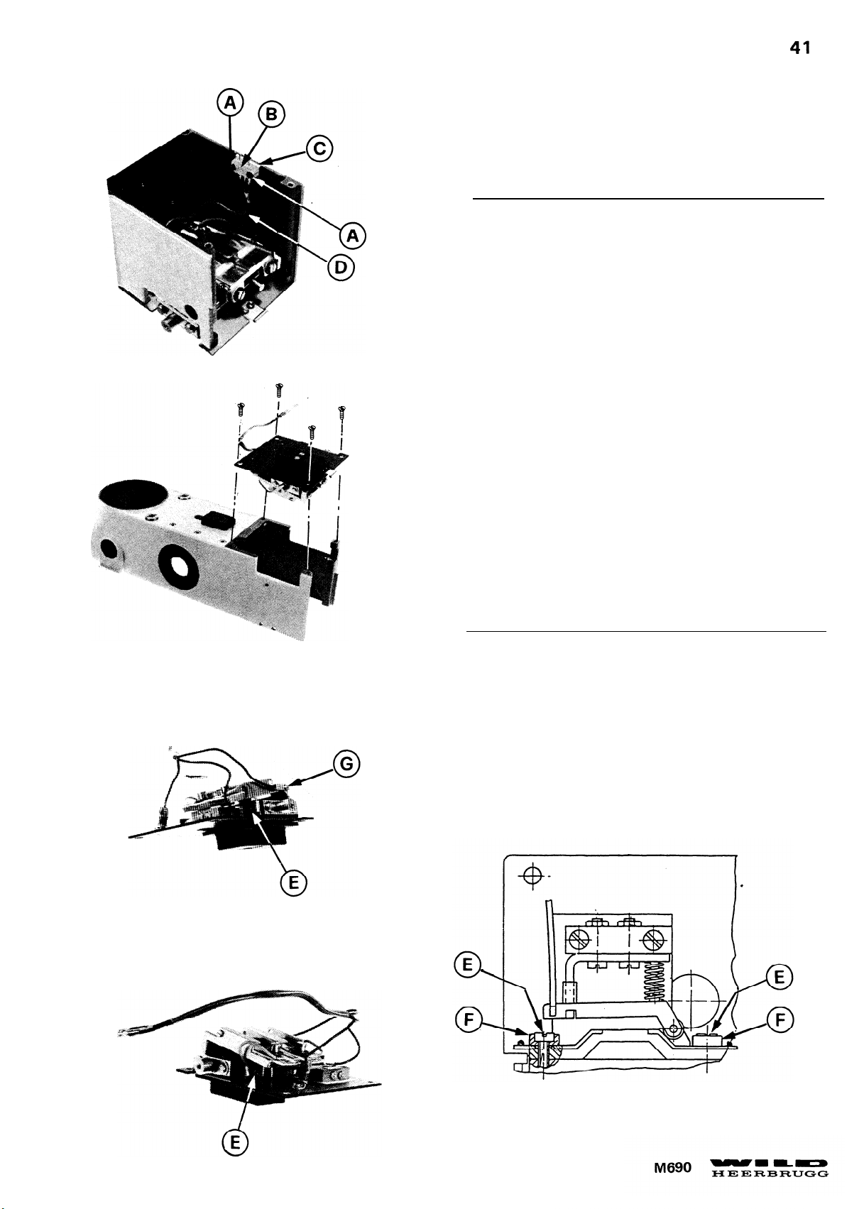
2 Muttern (A) , Stecker (B) und Unterlage (C)
demontieren.
Montagehinweis:
Kabel (D) bis zur Seitenwand ganz am Boden verlegen.
Remove 2 nuts (A) , plug (B) and underlay (C) .
Assembly instructions:
Lay out cable (D) completely at bottom to side wall.
2 Schrauben (E) , Isolationsbüchsen (F) und Kabel (G)
demontieren.
Remove 2 screws
(E), insulating bushes (F) and cable (G)
Page 48
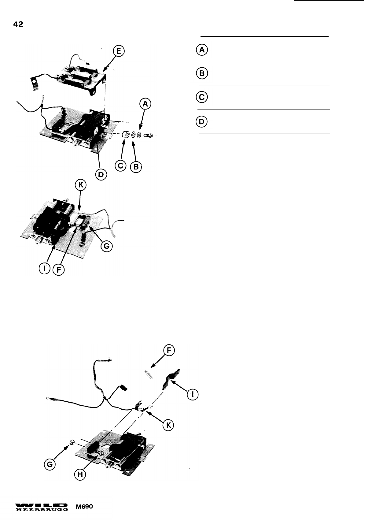
U-Scheibe
Washer
Isolierscheibe
Insulating washer
Isolierbüchse
Insulating bush
Isolierplatte
Insulating plate
Justierung Schlitten (E) siehe Seite 45.
To adjust slide (E) see page 45.
Feder (F) , 2 Muttern (G) ,
2 Schrauben (H) ,
mit Kabel demontieren.
(K)
Hebel
Isolierschiene (I) und-
Remove spring (F) ,2 nuts (G) ,
2 screws (H) , insulating rail (I) , and
lever (K) incl. cable.
Page 49
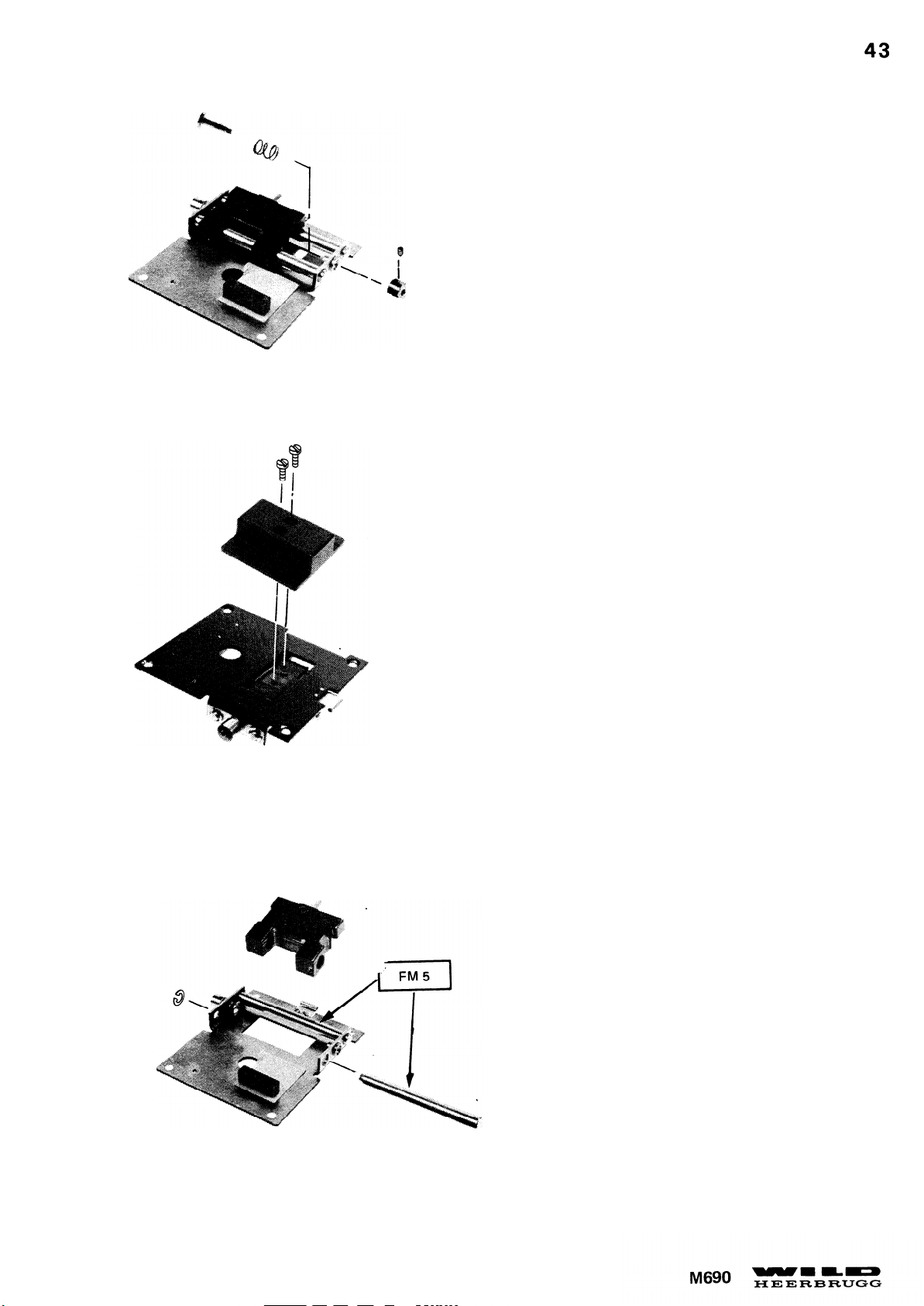
Justierung Lampenanschlag siehe Seite 47.
To adjust lamp stop see page 47.
Page 50
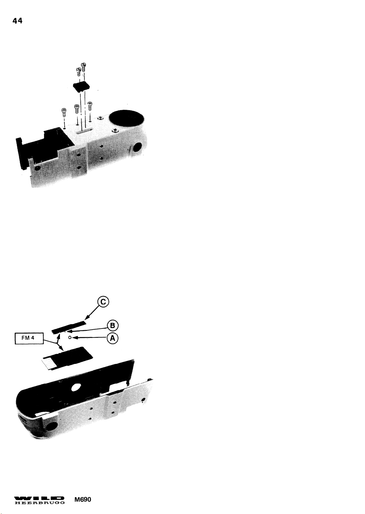
Achtung auf Kugel (A) und Feder (B)
Montagehinweis:
Durch Verschieben der Leiste (C) 0,5mm Spiel einstellen.
Take care with ball (A) and spring (B) .
Assembly instructions:
Displace ledge (C) to set 0,5mm clearance
Page 51
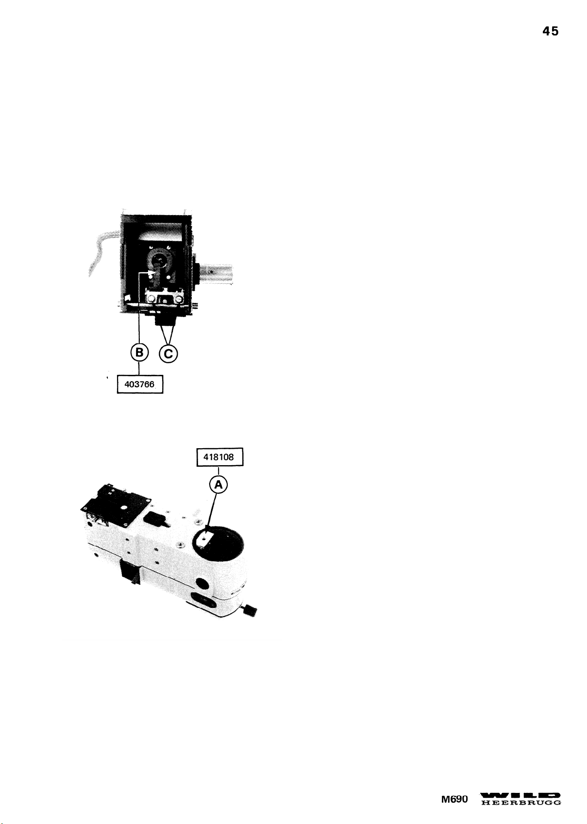
BELEUCHTUNG JUSTIEREN
ADJUSTING ILLUMINATION
Lampenzentrierung Höhe:
Die Bohrung der Aufsteckblende (A) muss zur Hälfte
vom Zentriereinsatz (B) abgedeckt sein.
Korrektur:
Centring lamp vertically:
The centring insert (B) must cover half the opening of
the diaphragm attachment (A) .
2 Schrauben (C) lösen und Lampenträger in der Höhe verschieben.
Correction: Slacken 2 screws (C) and displace
lamp carrier vertically.
Page 52
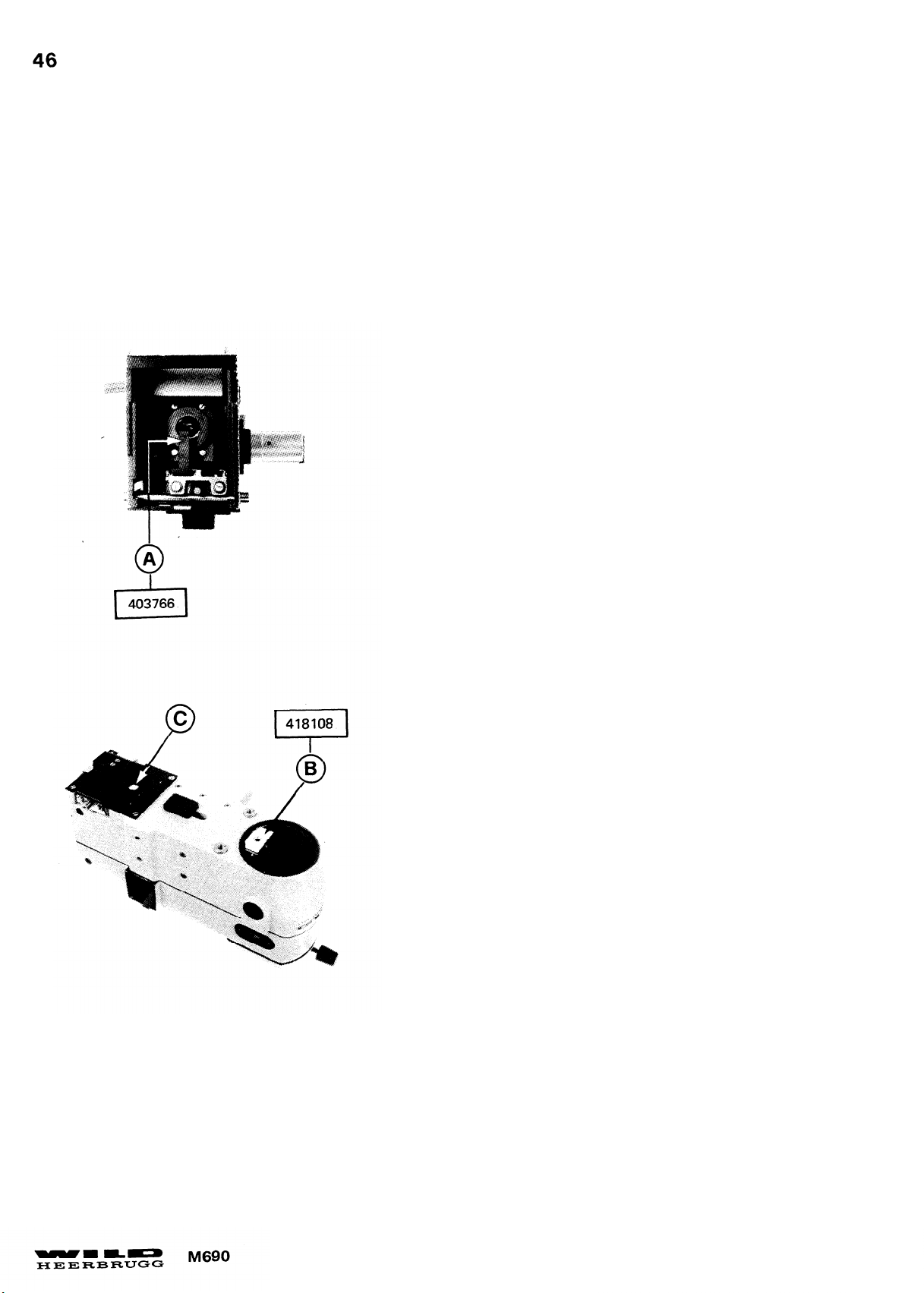
BELEUCHTUNG JUSTIEREN
ADJUSTING ILLUMINATION
Lampenanschlag einstellen:
Der Zentriereinsatz (A) muss in der Ebene der Aufsteckblende (B) scharf abgebildet sein. Kontrolle mit Lupe.
Korrektur:
- Kondensorschlitten nach vorne schieben.
- Zentriereinsatz gegen Anschlag drücken. Durch Loch (C)
Exzenterschraube be verdrehen.
Set lamp stop:
The image of the centring insert (A) must be in sharp
focus in the plane of the diaphragm attachement (B) .
Correction:
- Press centring insert against stop.
- Turn eccentric screw through hole (C) .
Page 53
BELEUCHTUNG JUSTIEREN
ADJUSTING ILLUMINATION
Lampenzentrierung Seite:
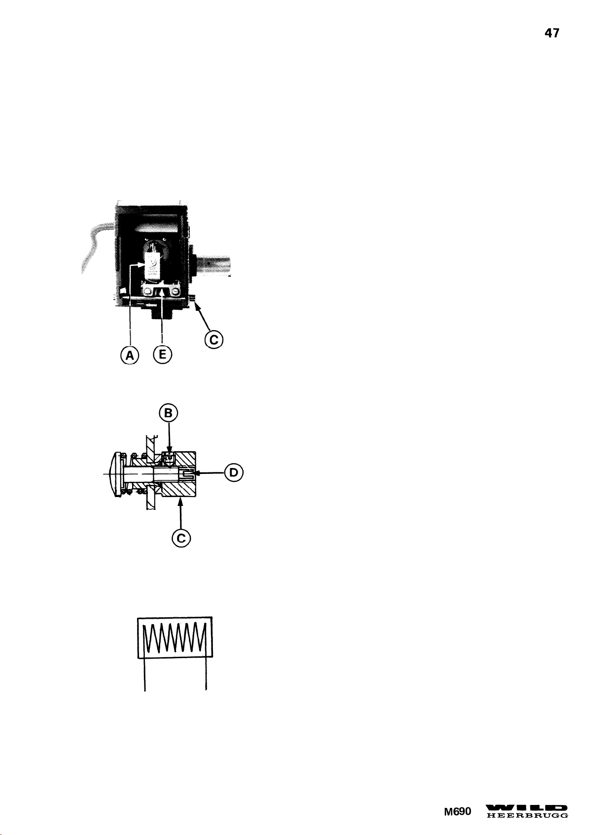
Der Glühwendel der Halogenlampe (A) muss seitlich zum
Beleuchtungsprisma zentriert sein.
Korrektur:
Schraube (B) lösen, Mutter (C) festhalten und Anschlag (D)
ein- oder ausdrehen. Grosse Fehler durchschieben des
Lampenträgers (E) korrigieren.
Achtung: Nur mit neuer Lampe zentrieren.
Centring lamp horizontally:
The filament of the halogen lamp (A) must be centred
horizontally on the illumination prism.
Correction:
- Slacken screw (B
or out.
- Correct big errors by moving the lamp carrier (E).
), hold nut (C) and screw stop (D) in
Caution: Center only with new bulb.
Page 54
BELEUCHTUNG KONTROLLIEREN
CONTROL OF ILLUMINATION
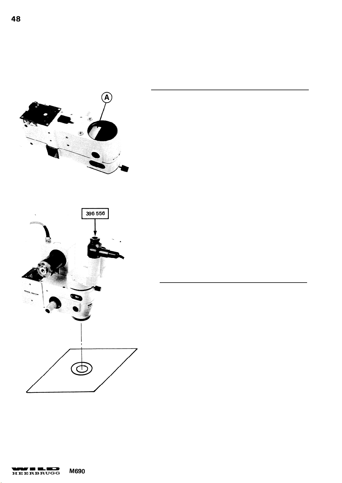
Papier (A) auf Beleuchtungsprisma legen. Beleuchtung
einschalten. Scharfe Abbildung und zentrische Lage des
Wendelbildes kontrollieren.
Check centring of lamp. Place paper (A) on illumination prism.
Switch illumination on and check correct focusing and centring
of lamp filament.
- Binokulartubus mit Autokollimations- oder Fadenkreuzokular montieren.
- Auf Papier 2 Kreise ø 30mm und 60mm aufzeichnen.
Kreiszentrum zu Fadenkreuz zentrieren.
- Zentrische Lage, Ausleuchtung und Durchmesser
des Leuchtflecks kontrollieren.
- Fit binocular tube with autocollimation- or crosshair
eyepiece to optic carrier.
- Draw 2 circles of 30mm and 60mm diam. on paper and
center circle center relative to crosshair.
- Check centring, size and eveness of luminous spot.
Page 55

Die Beleuchtungsoptik und der Glühwendel sind korrekt justiert, wenn ein gleichmässig ausgeleuchteter
Lichtfleck entsteht, der dem Gesichtsfeld zentrisch überlagert ist und dessen Rand mit dem Bild gleich-
zeitig scharf erscheint.
1. Leuchtfleckgrösse:
2. Zentrische Lage:
Bei stärkster Vergrösserung =
Bei schwächster Vergrösserung =
Maximale Abweichung 2mm
30 ± 1mm
63 ± 1mm
3. Ausleuchtung: Es dürfen keine gelblichen Randpartien oder blaue Flecken auftreten.
4. Zoom für Beleuchtung:
Der Beleuchtungszoom muss von der Zoomstellung ca. 14x bis zur
stärksten Vergrösserung und zurück mitgenommen werden.
The illumination optics and the lamp filament are correct adjusted when a evenly illuminated luminous
spot covers the field of view concentric. The seem of the luminous spot and the field of view must be
sparp in focus in the same plane.
1. Size of luminous spot: At max. magnification = 30 ± 1mm
At min. magnification = 60 ± 1mm
2. Centring:
3. Illumination:
Maximum deviation 2mm
No yellow seems or blue spots may appear.
4. Zoom movement for
illumination:
The zoom for illumination must be carried on from max. magnification to
approx. 14x magnification and back again.
Page 56
SPEZIAL WERKZEUGE
SPECIAL TOOLS
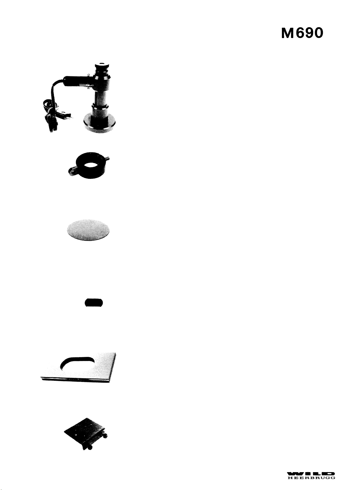
106613
411053
Autokollimator
Autocollimator
Halter für Autokollimator 106613
Support for autocollimator 106613
213108
381499
355546
Planspiegel
Plan mirror
Spiegel
Mirror
Platte
Plate
418107
Haltewinkel für 355546
Clamping bracket for 355546
Page 57
M690
SPEZIAL WERKZEUGE
SPECIAL TOOLS
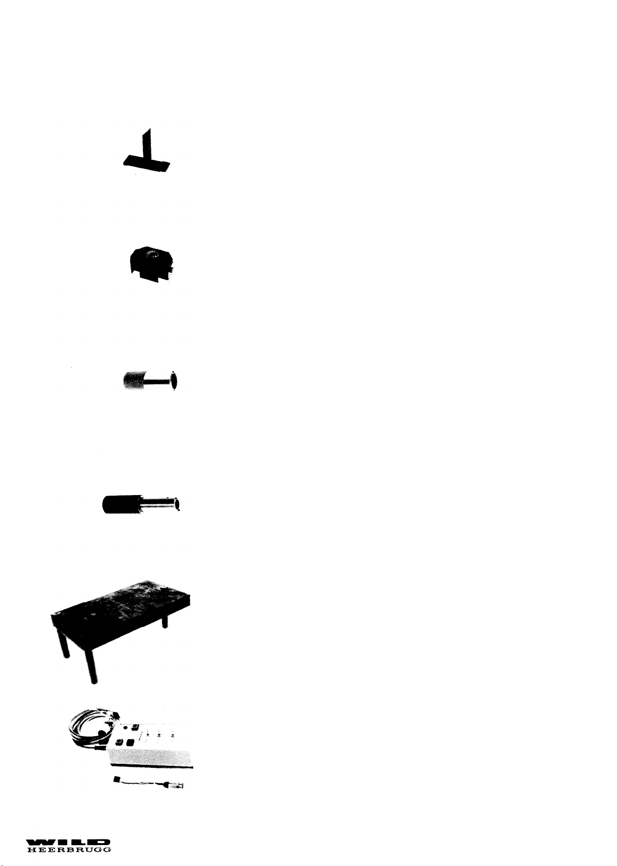
403766
418108
415055
Lampenzentriereinsatz
Lamp centring insert
Aufsteckblende
Mask attachment
Klauenschlüssel für Zoomobjektive
Claw spanner for zoom objectives
422009
377334
418078
Stiftenschlüssel für Triebkasten
Pin spanner for drive housing
Kontrollplatte horizontierbar
Leveling control plate
Testbox
Testbox
Page 58
SERVICE MANUAL
DOC CODE SML 556 912
OPTICS CARRIER
V.1990
M690 ELEKTRISCHER TEIL
Testbox
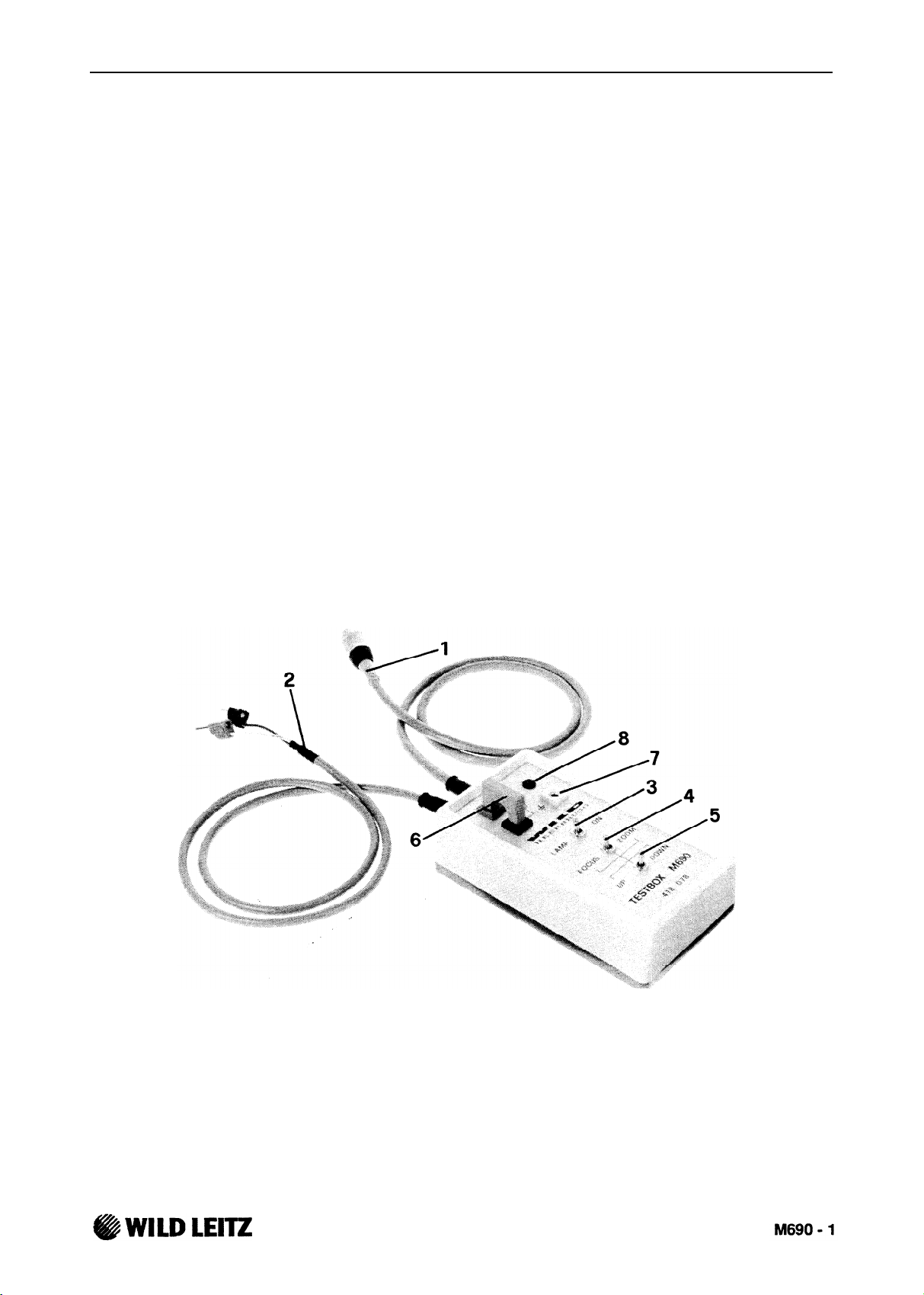
Zur Kontrolle und Justierung des M690 Optikträgers wird eine Testbox 418 078 angeboten.
Mit ihr ist es möglich, den Zoom- und Fokusmotor ohne MEL anzusteuern, sowie die Motor- und
Lampenströme zu messen.
Funktionen der Testbox
Kabel (1) zu M690 Horizontalarm, rechte Buchse.
Schalter (3) für Mikroskoplampe.
( In Position LAMP ausgeschaltet. )
UP/DOWN- Taste (5)
( mit (4) gewählter Motor wird angesteuert )
Erdungsbuchse (7) zur Kontrolle der Erd-
Verbindung zum M690.
- KONTROLLE, REPARATUR
Speisekabel (2) zu einem Netzgerät.
( rot = positiv, schwarz = negativ )
Wählschalter (4) für Zoom- oder Fokusmotor
Buchsen (6) zur Strommessung.
Kontroll- LED (8), leuchtet, wenn Spannung an
Testbox.
Vorbereitungen zur Kontrolle und Reparatur
Testbox an Netzgerät und an M690 anschließen. Schalter (3) auf Position LAMP (aus).
Kabelverbindungen siehe auch Service Manual 690 Seiten 1-2.
Page 59
OPTICS CARRIER
v.1990
SERVICE MANUAL
DOC CODE 556 912
Kontrolle des Focusmotors
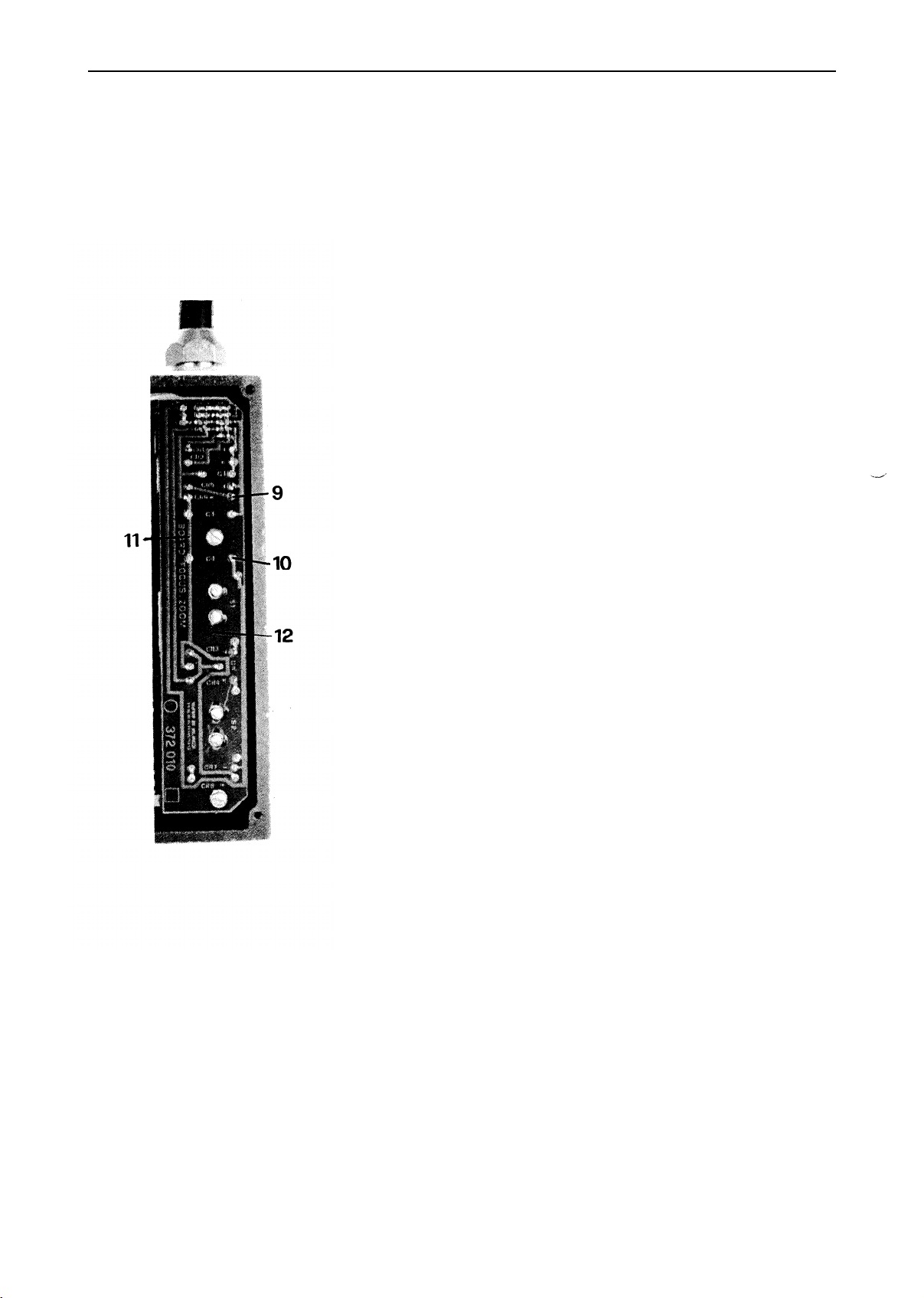
Messen auf Focus/Zoom-Board (12) zwischen (11) GND und (10).
Voltmeter auf Bereich > 20VDC. Schalter (4) auf Zoom.
5VDC einspeisen in Kabel (2).
Spannung (11)-(10):
bei Taste (5) UP=
-4VDC
bei Taste (5) DOWN= +4VDC
Brücke an (6) entfernen,
Amperemeter, Bereich > 1 ADC, anschließen.
Strom bei Taste (5) UP/DOWN = 400mADC
Schlittenbewegung Anschlag - Anschlag in = 15 sec.
10VDC einspeisen in Kabel (2).
Spannung (11)-(10):
bei Taste (5) UP=
-9VDC
bei Taste (5) DOWN= +9VDC
Strom bei Taste (5) UP/DOWN = 500mADC
Schlittenbewegung Anschlag - Anschlag in = 6.5 sec.
Stromaufnahme Motor, ohne Last bei 5V Speisung = 270mADC.
Motorwiderstand: Stecker J19 ausgezogen. Ohmmeter
auf Bereich Ohm x1 , messen J19/1- J19/2 ≈ 2
Ω
Kontrolle des Zoommotors
Messen auf Focus/Zoom-Board (12) zwischen (11) GND und (9).
Voltmeter auf Bereich > 20VDC. Schalter (4) auf Zoom.
5VDC einspeisen in Kabel (2).
Spannung (11)-(9):
Brücke an (6) entfernen, Amp-Meter, Bereich > 1ADC, anschließen.
Strom bei Taste (5) UP/DO
Zoombewegung Anschlag -l
10VDC einspeisen in Kabel
Spannung (11)-(9):
Strom bei Taste (5) UP/DO
Zoombewegung Anschlag - Anschlag in ≈ 2 - 2.5 sec.
Stromaufnahme des Motors ohne Last bei 5V Speisung = 5 mADC.
Motorwiderstand: Stecker J18 ausgezogen. Ohmmeter
auf Bereich Ohm x1, messen J18/5- J18/8 ≈ 21
Fehler
Keine Spannung, kein Strom
Strom an (6) ohne Motor
Spannung vorhanden, ohne Strom
Zu großer Strom mit Motor angeschlossen
bei Taste (5) UP=
bei Taste (5) DOWN= -4VDC
WN = 70 - 120 mADC.
Anschlag (V7 - V36) in ≈ 5-6 sec.
(2)
bei
Taste (5) UP=
Taste (5) DOWN= -9VDC
bei
WN ≈ 140 - 190 mADC
Mögliche Ursachen
Board, Verdrahtung.
Board, Verdrahtung.
Motor, Anschluss.
Motor, Mechanik.
+4VDC
+5VDC
Ω
M690-2
@WILD LEITZ
Page 60
SERVICE MANUAL
OPTICS CARRIER
DOC CODE SML 556 912
Kontrolle der Endschalter Zoom, Focus
Endschalter muß Motorspannung unterbrechen, bevor Focus oder Zoom mechanisch aufläuft.
Die Gegenrichtung darf dabei nicht blockiert werden.
Vorbereitung und Meßpunkte wie vorherige Seite.
V.1990
Focus:
Zoom:
Spannung (11) - (10)
Spannung (11) - (9)
Schalter (5) UP ≈ 4VDC.
Schalter (5) DOWN ≈ +4VDC.
Endschalter gedrückt 0V.
Endschalter gedrückt 0V.
Justierung der Endschalter siehe die Seiten 5, 16, 18, 23, 24, 25 im M690 Service Manual.
Kontrolle der Lampe
Brücke an (6) entfernen,
Amperemeter, Bereich > 3ADC, anschließen.
Voltmeter Bereich > 20VDC.
Lampe entfernen.
10V einspeisen, Strom auf 3A begrenzt.
Schalter (3) auf ON.
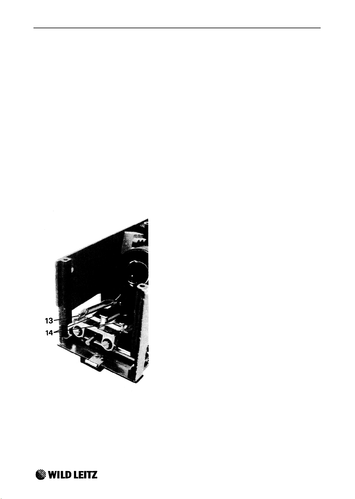
Spannung (13) - (14): 10V muß vorhanden sein.
Strom (6): Es soll kein Strom fließen.
Beide Lampenpositionen kontrollieren.
Wenn nicht korrekt, Verdrahtung und Lampenträger
kontrollieren.
Schalter (3) auf LAMP.
Lampe einsetzen und Schalter (3) auf ON.
Spannung (13) - (14): = 5.5 VDC
Strom (6):
= 3 ADC
Lampe muß leuchten.
Beide Lampenpositionen kontrollieren.
Wenn nicht korrekt, Lampe, Verdrahtung und
Lampenträger kontrollieren.
M690-3
Page 61
OPTICS CARRIER
V.1990
M690, ELECTRICAL PART - INSPECTION AND REPAIR
Test box
SERVICE MANUAL
DOC CODE 556 912
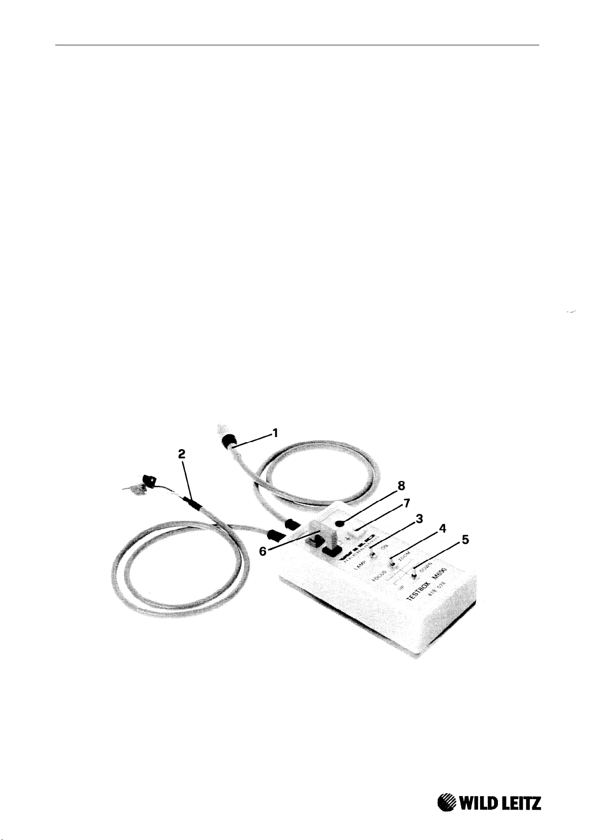
A test box
(418
078) can be supplied for inspecting and adjusting the M690 optics carrier. It enables
the zoom and focus motors to be operated without MEL, and also enables the motor- and lamp currents to be measured.
Functions of the test box
Connect cable (1) to the M690 horizontal arm,
right-hand socket.
Switch (3) is for the microscope lamp
(switched off in position LAMP).
(5) is the UP/DOWN switch
Connect feeder cable (2) to a DC supply.
(red = positive, black = negative).
The selector switch (4) is for the zoom- or
focus- motor.
Sockets (6) are for measuring current.
(motor selected with (4) is controlled).
Earthing socket (7) is for inspecting the
earth connection to the M690.
LED (8) shines when there is a voltage within
the test box.
Preparations for inspection and repair
Connect test box to DC supply and to M690. Set switch (3) to position LAMP (off).
Refer to pages 1-2 for information on cable connections.
M690-4
Page 62
SERVICE MANUAL
DOC CODE SML 556 912
OPTICS CARRIER
V.1990
lnspection of focus motor
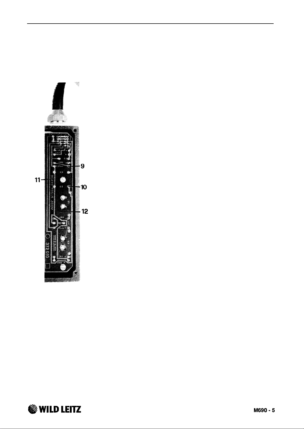
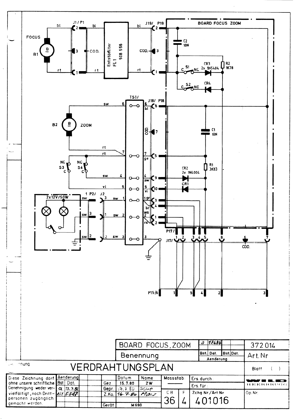
Measure on focus/zoom board
(12)
between (11) GND and (10).
Voltmeter on range 20VDC. Switch (4) on Zoom.
Supply 5VDC to cable (2).
Voltage (11)-(10):
At key (5) UP ≈ -4VDC
At key (5) DOWN ≈ +4VDC
Remove bridge from (6) and connect ammeter, range 1ADC.
Current at key (5) UP/DOWN ≈ 400mADC
Sledge movement from stop to stop in ≈ 15 sec.
Supply 10VDC to cable (2).
Voltage (11)-(10): At key (5) UP ≈ 9VDC
At key (5) DOWN ≈ +9VDC
Current at key (5) UP/DOWN ≈ 500mADC
Sledge movement from stop to stop in ≈ 6.5sec.
Current taken by motor (without loading) at 5V ≈ 270mADC.
Motor resistance: Plug J19 pulled out.
Ohmmeter in range Ohm xl ; value of J19/1 - J19/2 ≈ 2
Ω
lnspection of zoom motor
Measure on focus/zoom board (12) between (11) GND and (9).
Voltmeter in range 20VDC. Switch (4) on Zoom.
Supply 5VDC to cable (2).
Voltage (11)-(9): At key (5) UP ≈ +4VDC
At key (5) DOWN ≈ -4VDC
Remove bridge from (6) and connect ammeter, range 1ADC.
Current at key (5) UP/DOWN ≈ 70 - 120 mADC.
Zoom movement from stop to stop (V7 - V36) in ≈ 5-6sec.
Supply 10VDC to cable (2).
Voltage (11)-(9): At key (5) UP ≈ +9VDC
At key (5) DOWN ≈ -9VDC
Current at key (5) UP/DOWN ≈ 140 - 190 mADC
Current taken by motor (without loading) at 5V ≈ 5mADC.
Motor resistance: Plug J18 pulled out.
Ohmmeter in range Ohm xl ; value of J18/5 - J18/8 ≈ 21
Error Possible causes
No voltage, no current
Current at (6) without motor
Voltage present, but no current
Current too great when motor connected
Board, wiring.
Board, wiring.
Motor, connection.
Motor, mechanical parts.
Ω
Page 63
OPTICS CARRIER
V.1990
SERVICE MANUAL
DOC CODE 556 912
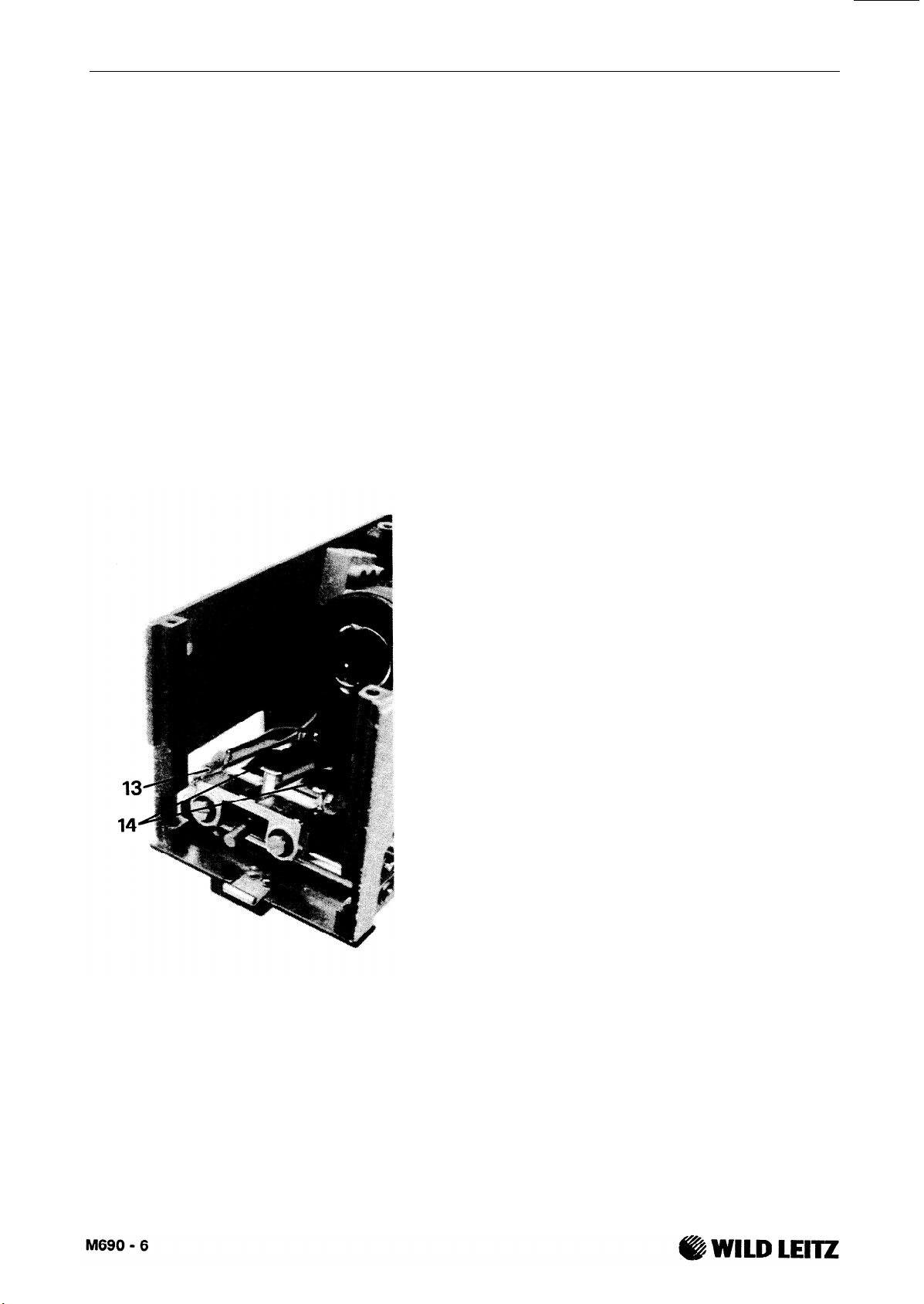
lnspection of limit switches for zoom and focus
The limit switches must interrupt the motor voltage before the focus or the zoom strikes
mechanically.
The opposing direction is not to be blocked during this process.
Refer to previous page for information on preparation and measuring points.
Focus:
Zoom:
Voltage (11) - (10)
Voltage (11) - (9)
Switch (5) UP ≈ -4VDC.
Switch (5) DOWN ≈ +4VDC.
Limiting switch depressed 0V.
Limiting switch depressed 0V.
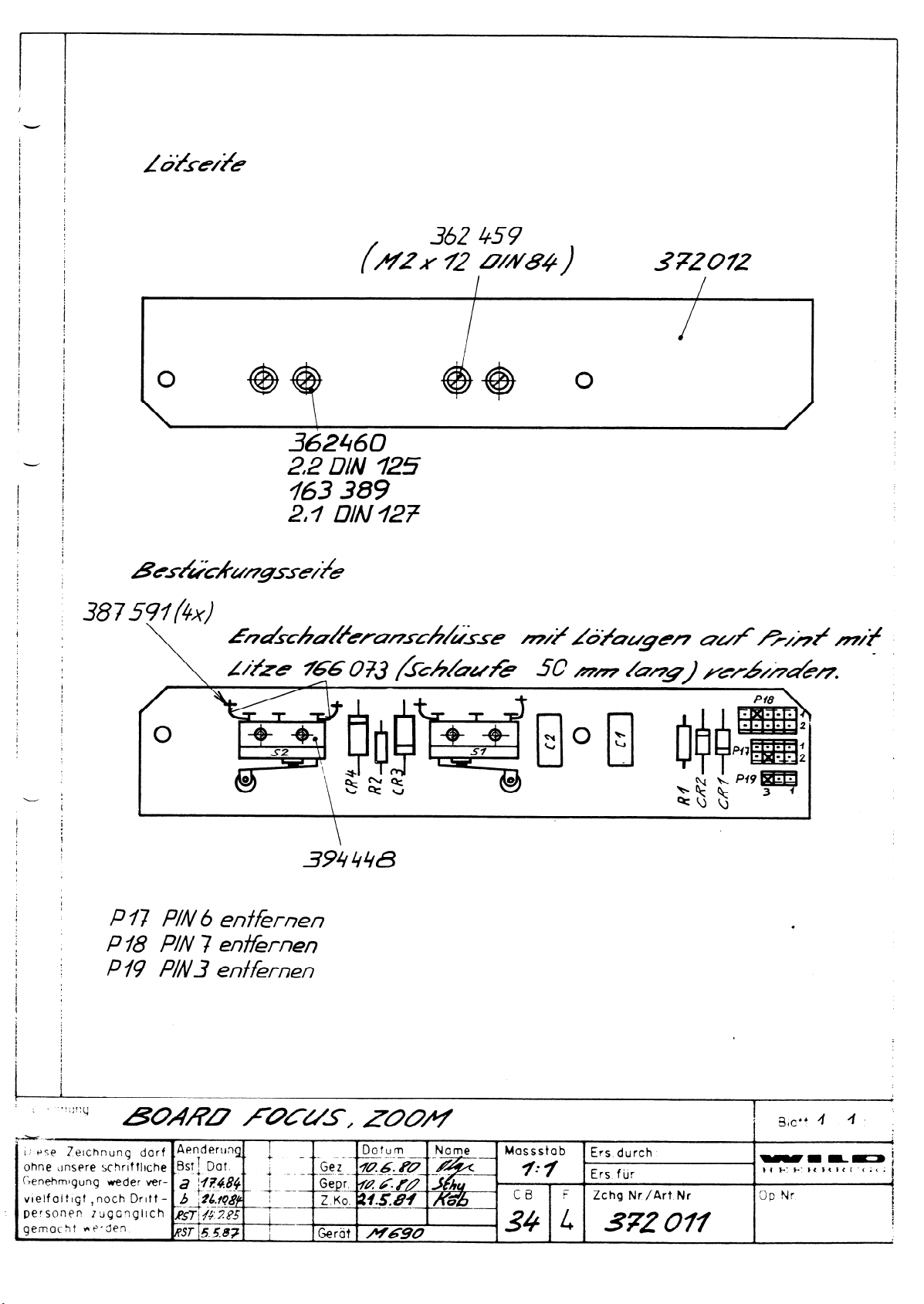
To adjust the limit switch, refer to pages 5, 16, 18, 23, 24 and 25 in the M690 Service Manual.
Inspecting the lamp
Remove the bridge from (6).
Connect the ammeter, range 3ADC.
Voltmeter range is 20VDC.
Remove the lamp.
Supply 10V. Limit the current to 3A.
Set switch (3) to ON.
10V must be present between (13) and (14).
No current should flow at (6).
Inspect both lamp positions.
If incorrect, inspect wiring and lamp carrier.
Set switch (3) to LAMP.
Insert lamp and set switch (3) to ON.
Voltage (13) - (14):
Current (6):
≈
5.5VDC
≈
3ADC
The lamp must shine.
Check on both lamp positions.
If incorrect, inspect lamp, wiring, and lamp carrier.
Page 64
Page 65
Page 66
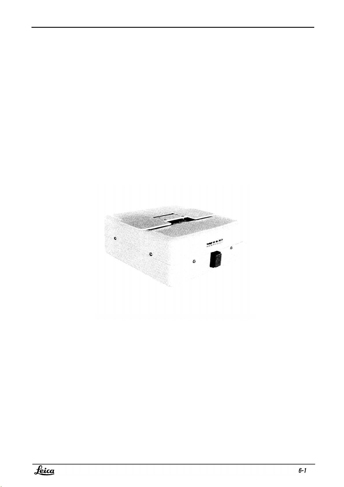
Service Manual Stands/Stages MSV104
Doc Code 556 913
05/94 3691-DMF
MSV 104 X-Y Kupplung
MSV 104 X-Y Unit
Page 67
MSV104
05/94 3691-DMF
Service Manual Stands/Stages
2x
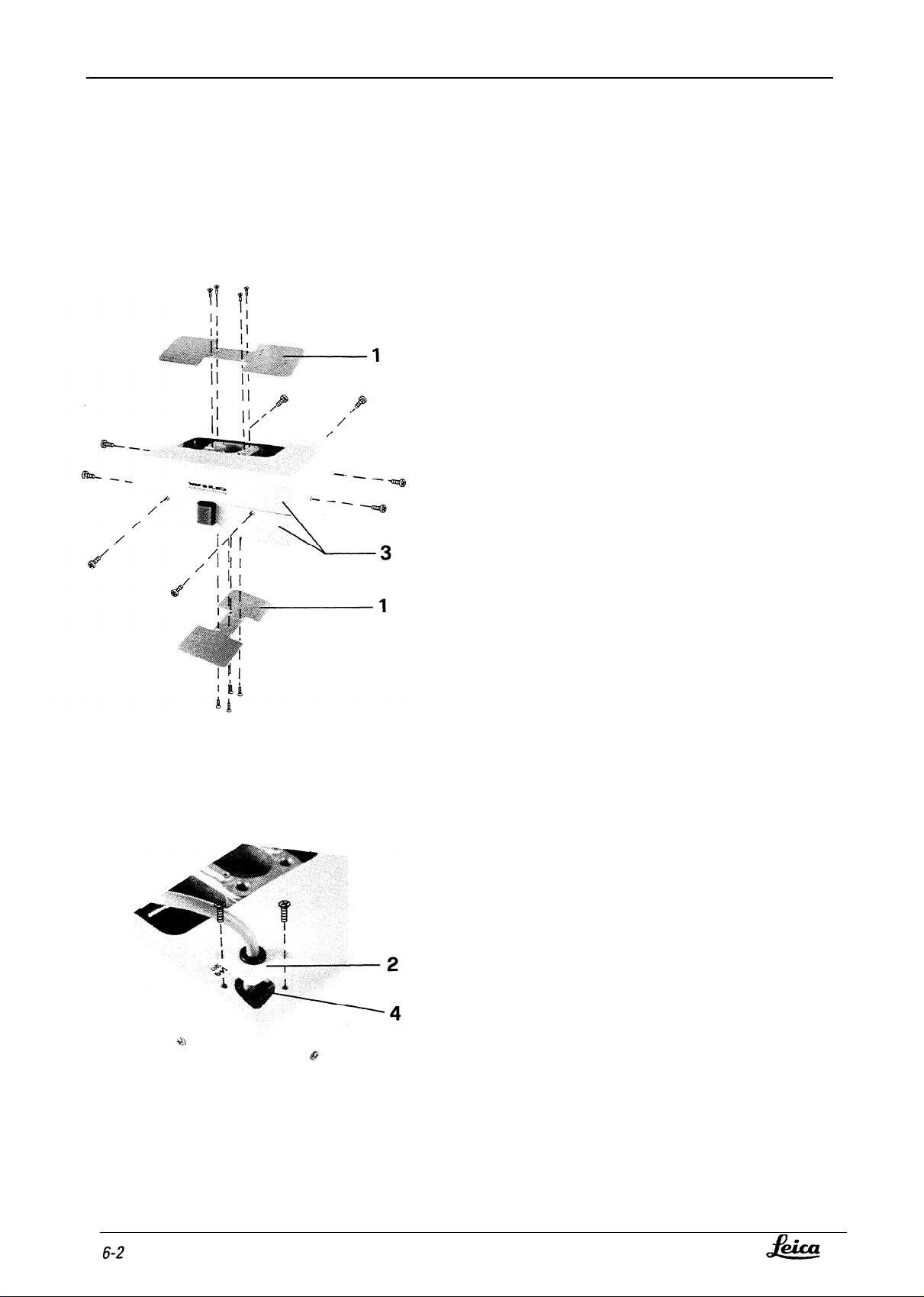
Abdeckbleche (l), Kabelhalterung (2),
obere und untere Abdeckung (3)
demontieren.
Kabel mit Kabelhalterung durch Öffnung
(4) ziehen.
Remove 2 cover plates (l), cable holder
(2), and upper
Pull cable and
and lower covers (3).
cable holder through
opening (4).
Doc Code 556 913
Page 68
Service Manual Stands/Stages
Doc Code 556 913
MSV104
05/94 3691-DMF
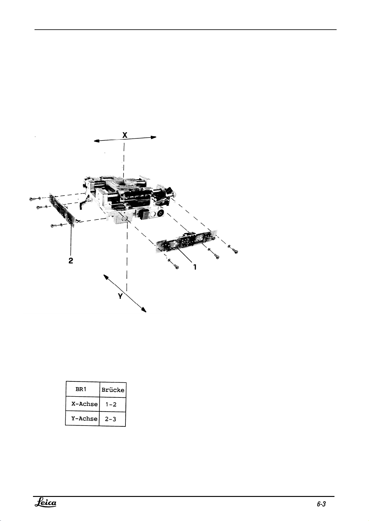
Switch Board (1) zu X-Achse (oben) und Switch Board
(2) zu Y-Achse (unten) demontieren.
Montage:
Brücken auf den Switch Boards für X- und Y-Achsen
setzen.
Remove Switchboard (1) for X-spindle (upper part) and
Switchboard (2) for Y-spindle (lower part).
Assembly:
Place bridges on the switchboards for
X- and Y-spindles.
Page 69
MSV104
05/94 3691-DMF
Service Manual Stands/Stages
Doc Code 556 913
Page 70

Service Manual Stands/Stages
Doc Code 556 913
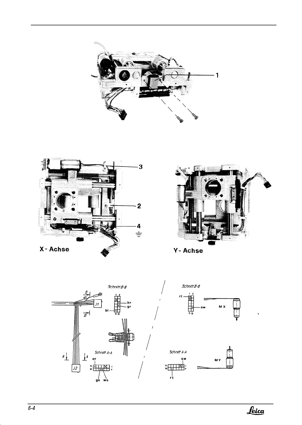
Kabelbaum demontieren:
Schrauben zu Druckschalter (l), 3 Briden (2), 5 Briden (3) demontieren, Erdung (4) abschrauben.
Stecker, J1 (X-Achse) und J2 (Y-Achse), freilegen.
Litzen zu Druckschalter und zu DC-Motoren aus Stecker J1 und J2 ziehen.
Remove cable bundle:
Remove screws of pressure switch (1) and also 3 Clips (2) and 5 Clips (3).
Unscrew earth Connection (4). Uncover plugs J1 (X-axis) and J2 (Y-axis).
Pull wires of pressure switch and of DC motors out of plugs J1 and J2.
MSV104
05/94 3691-DMF
Page 71
MSV104
05/94 3691-DMF
Service Manual Stands/Stages
Doc Code 556 913
Page 72

Service Manual Stands/Stages
Doc Code 556 913
MSV104
05/94 3691-DMF
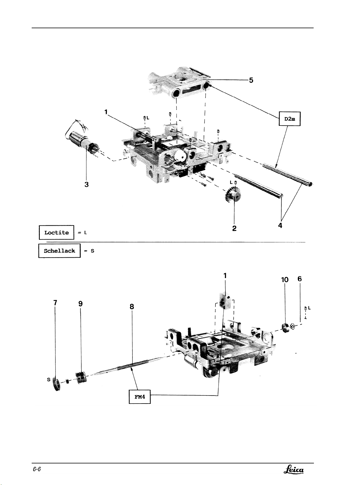
X-Achse demontieren:
Gew.Stift in Spindelmutter (1) lösen. Geradstirnrad (2), Motor (3), 2x Führungswellen (4) und Laufwagen (5)
demontieren.
Montage:
Spiel zwischen Laufwagen und Spindelmutter mit Gew.Stift einstellen.(Gew.St.ift bis Anschlag drehen, dann 1/8
Umdrehung zurück).Gew.Stift sichern. Langsspiel des Laufwagens inklusiv Spindel: max. 0.2mm.
Removing X-spindle:
Slacken grubscrew in nut (1) of spindle. Remove Straight spur gear (2), motor (3), 2 guide shafts (4), and carriage (5).
Assembly:
Using grubscrew, adjust play between carriage and nut of spindle. (Rotate grubscrew to stop and then anticlockwise by
1/8 turn). Secure grubscrew.
Maximum allowable longitudinal play of carriage and spindle together = 0.2mm.
Geradstirnrad (6), GewRing (7), Spindel (8), Spindelmutter (1), Kugellagerpaar (9) und Kugellager (10)
demontieren.
Montage:
Längsspiel der Spindel: max. 0.1mm.
Remove Straight spur gear (6), ring nut (7), spindle (8), nut (1) of spindle, double ballrate (9), and ballrate (10).
Assembly:
Maximum allowable longitudinal play of spindle = 0.1mm
Page 73
MSV104
05/94 3691-DMF
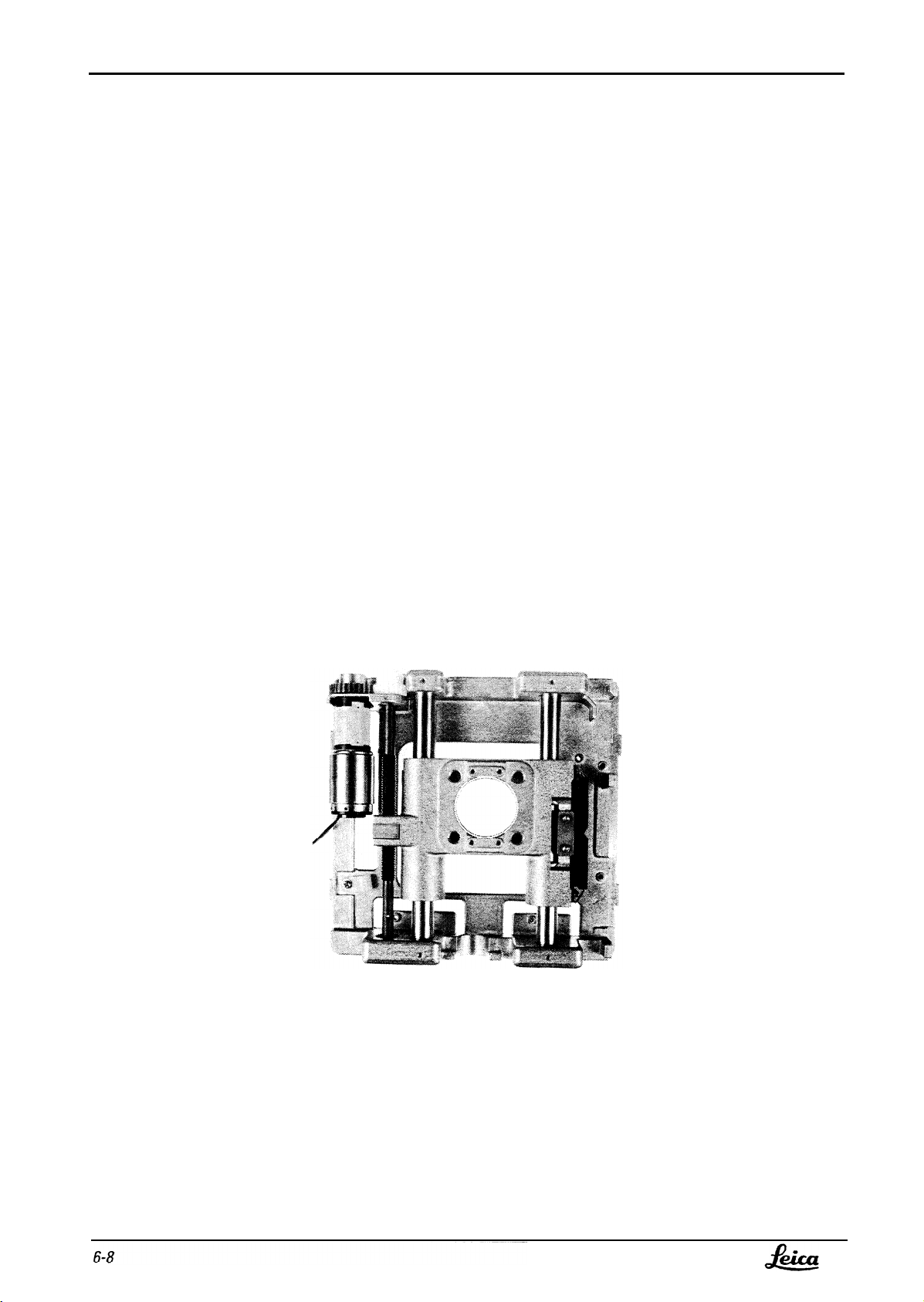
Demontage und Montage der Y-Achse: Analog der X-Achse.
The Y-spindle is removed and fitted in the same way as the X-spindle.
Service Manual Stands/Stages
Doc Code 556 913
Y-Achse demontieren:
Removing Y-spindle:
Page 74
Service Manual Stands/Stages
Doc Code 556 913
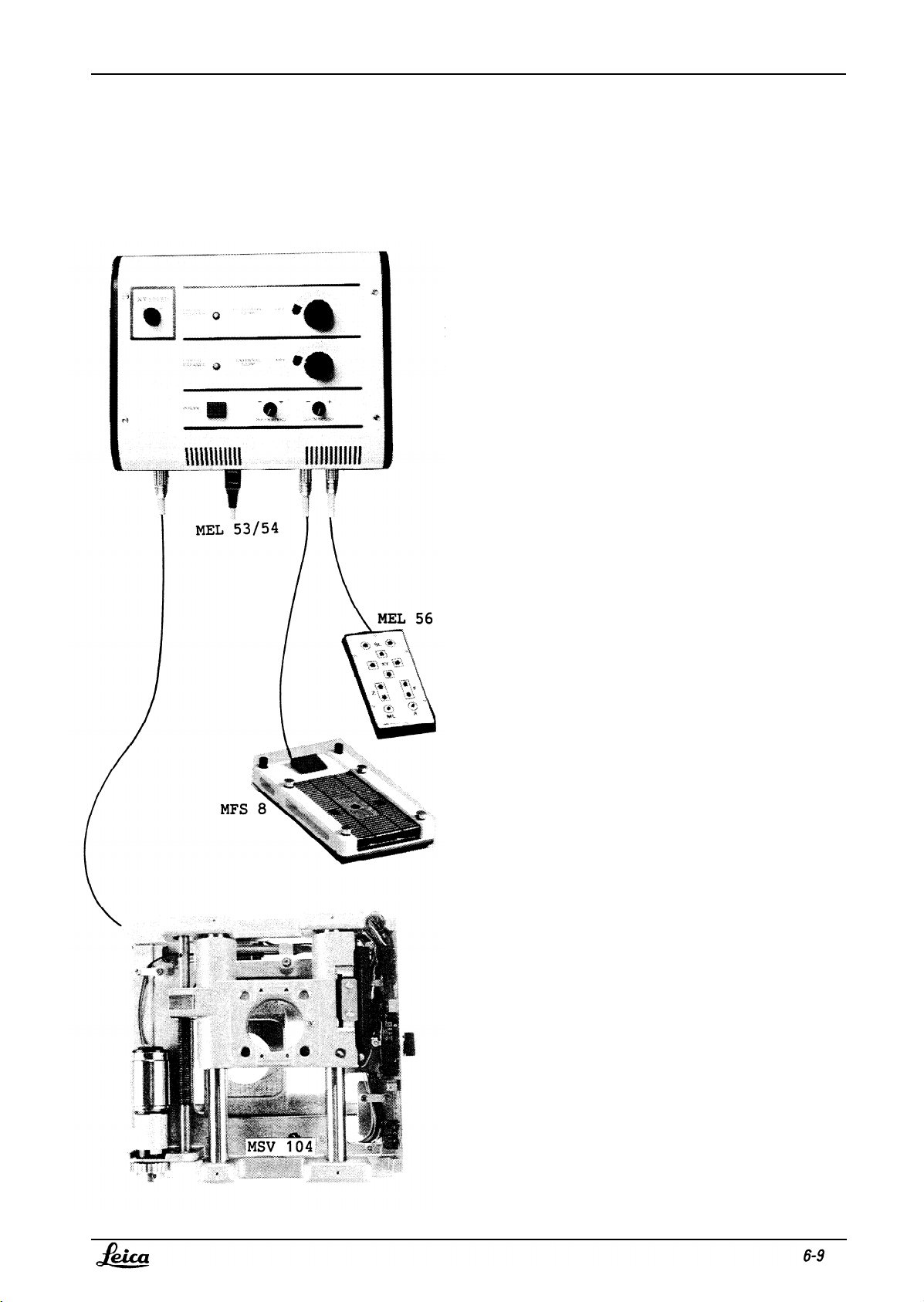
Schaltpunkte der Mikroschalter, der X und Y Achse, einstellen:
Setting Switching points of microswitches, X- and Y-spindles:
MSV104
05/94 3691-DMF
X-Y Kupplung (SMV 104), Hand- (MEL 56)
bzw. Fusschalter (MFS 8) an Steuergerät
MEL 53/54 anschliessen.
Connect XY-unit (SMV 104), handswitch (MEL 56) or
footswitch (MFS 8) to control unit MEL 53/54.
Page 75
MSV104
05/94 3691-DMF
Service Manual Stands/Stages
Doc Code 556 913
Page 76

Service Manual Stands/Stages
Doc Code 556 913
MSV104
05/94 3691-DMF
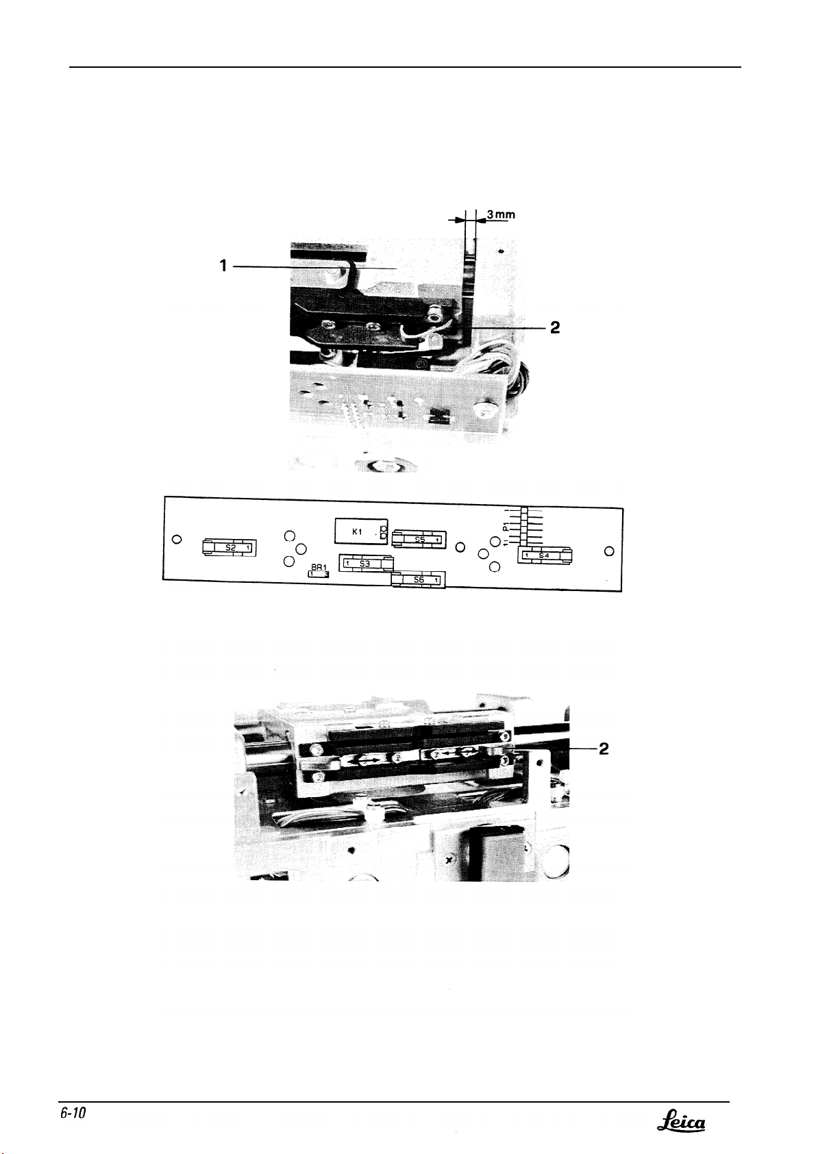
Geschwindigkeitsregler am MEL 53/54 auf minimum (2V) drehen.
Mit Laufwagen (1) 3mm vor mechanischen Anschlag fahren. Durch schieben derSchaltbüge (2), Schaltpunkte
der Endschalter S2 und S4, einstellen.
Bei max. Geschwindigkeit (12V) darf der Laufwagen den mechanischen Anschlag nicht erreichen.
(Gilt für X- und Y- Achse)
Turn speed regulator on MEL 53/54 to minimum (2V).
Move carriage (1) to 3mm before mechanical stop. Set Switching points of end switches S2 and S4 by
displacing switching bar (2). Carriage must not reach mechanical end stop of either spindle (X or Y) when
highest speed (with 12V) is used.
Page 77
MSV104
05/94 3691-DMF
Service Manual Stands/Stages
Doc Code 556 913
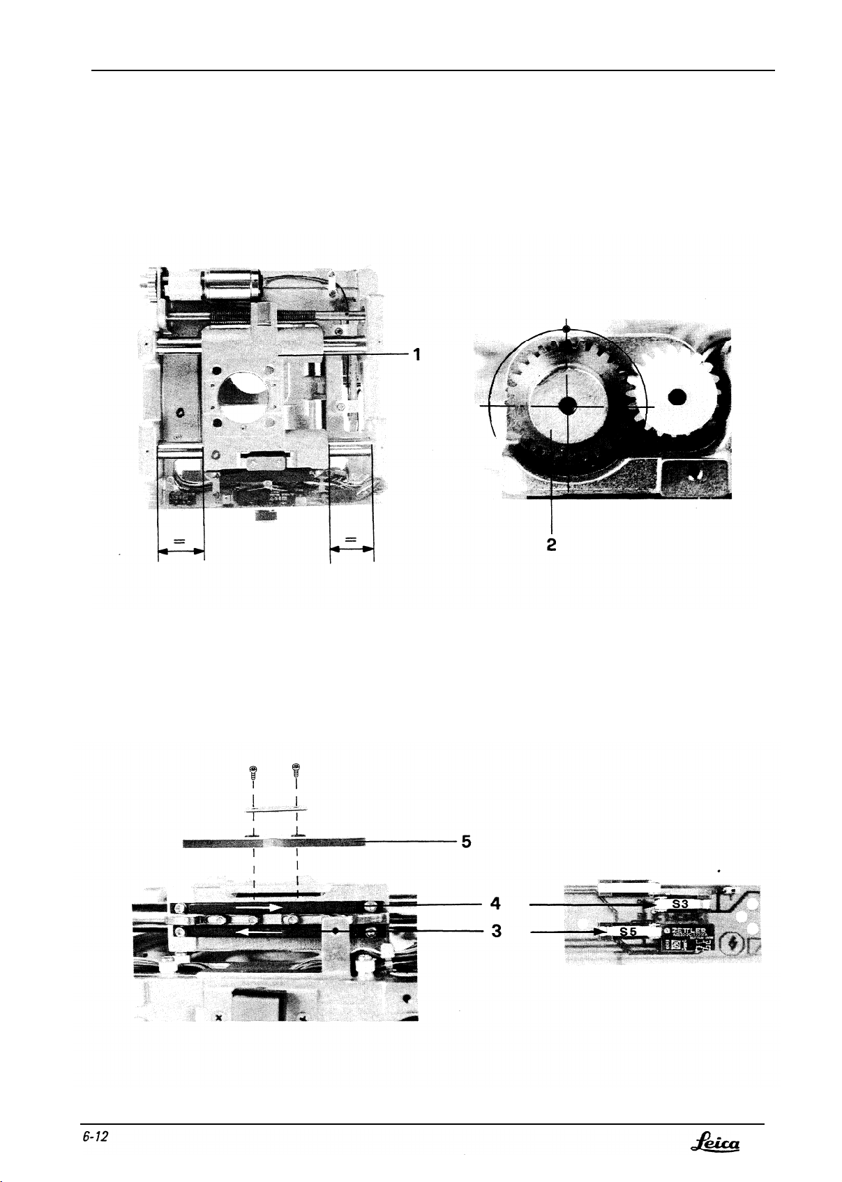
X- Achse
X- spindle
Page 78

Service Manual Stands/Stages
Doc Code 556 913
Schaltpunkte der X- Achse einstellen:
Laufwagen (1) in die Mitte des Arbeitsbereiches stellen, Mittelstellung am Motorstirnrad (2) markieren,
Schaltleiste (5) demontieren.
l Motorstirnrad in Mittelstellung, Schaltleiste (3) schieben bis Mikroschalter S5 betätigt wird.
l Motorstirnrad in Mittelstellung, Schaltleiste (4) schieben bis Mikroschalters S3 betätigt wird.
MSV104
05/94 3691-DMF
Kontrolle:
Zahnrad je ½ Umdrehung in CW und CCW aus derMittelstellung fahren.
Schalter S3 und S5 schalten aus.
In der Mittelstellung müssen beide Schalter noch eingeschaltet sein.
Setting Switching points of X-spindle:
Position carriage (1) at the mid-point of its range, mark mid-point on motor spur wheel (2), and remove
Switching ledge (5).
l Set motor spur wheel to its mid position and displace switching ledge (3) until microswitch S5 is
activated
l Set motor spur wheel to its mid position and displace Switching ledge (4) until microswitch S3 is
activated.
Inspection:
Displace cog by half a turn from its mid position, clockwise and counterclockwise.
Switches S3 and S5 switch off.
Both switches must remain switched on in the mid position.
Page 79
MSV104
05/94 3691-DMF
Service Manual Stands/Stages
Doc Code 556 913
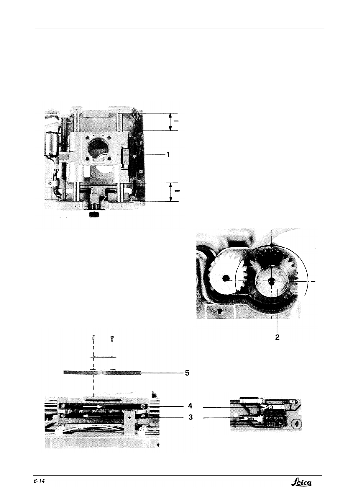
Y- Achse
Y- spindle
Page 80

Service Manual Stands/Stages
Doc Code 556 913
MSV104
05/94 3691-DMF
Schaltpunkte der Y- Achse einsteilen:
Laufwagen (1) in die Mitte des Arbeitsbereiches stellen, Mittelstellung am Motorstirnrad (2) markieren,
Schaltleiste (5) demontieren.
l
Motorstirnrad in Mittelstellung, Schaltleiste (3) schieben bis Mikroschalter S5 betätigt wird.
l
Motorstirnrad in Mittelstellung, Schaltleiste (4) schieben bis Mikroschalters S3 betätigt wird.
Kontrolle:
Setting Switching points of Y-spindle:
Position carriage
(1)
Switching ledge (5).
l
Set motor spur wheel to its mid position and displace switching ledge (3) until microswitch S5 is
activated.
l
Set motor spur wheel to its mid position and displace Switching ledge (4) until microswitch S3 is
activated.
Inspection:
Zahnrad je ½ Umdrehung in CW und CCW aus derMittelstellung fähren.
Schalter S3 und S5 schalten aus.
In der Mittelstellung müssen beide Schalter noch eingeschaltet sein.
at the mid-point of its range, mark mid-point on motor spur wheel (2), and remove
Displace cog by half a turn from its mid position, clockwise and counterclockwise.
Switches S3 and S5 switch off.
Both switches must remain switched on in the mid position.
Page 81
MSV104
05/94 3691-DMF
Service Manual Stands/Stages
Doc Code 556 913
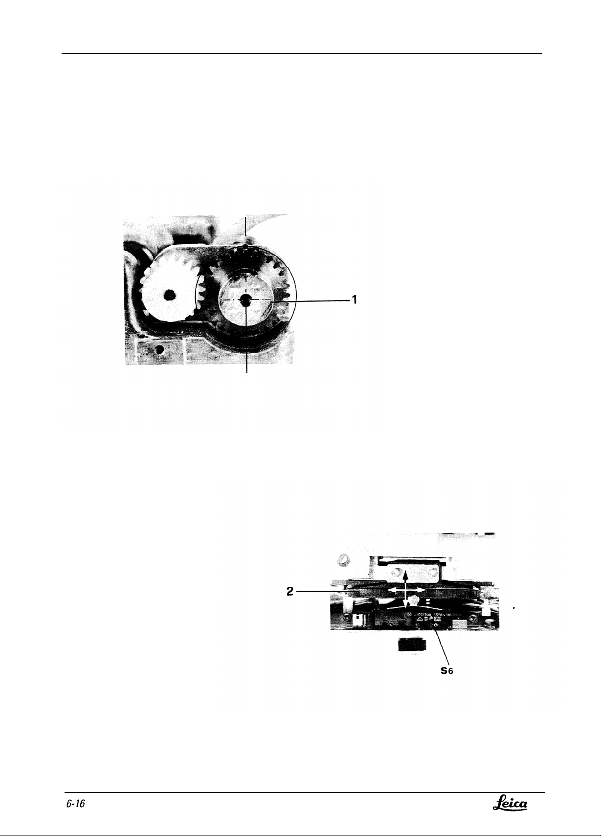
X- und Y-Achse:
X- and Y-spindles:
Page 82

Service Manual Stands/Stages
Doc Code 556 913
MSV104
05/94 3691-DMF
X- und Y-Achse:
Schaltleiste (2) montieren, mit X-und Y- LaufWagen in Mittelstellungfahren.
Schaltleiste (2) seitlich schieben, so dass Rolle des Endschalters S6 symetrisch in der V-Nute liegt
Schaltleiste (2) nach Vorne Bzw. nach Hinten schieben, Endschalter S6 bleibt innerhalb der ± 1/2
Umdrehung offen.
Mit X und Y Schlitten aus der Mittelstellung fahren, danach Rückstellknopf betätigen.
X und Y Schlitten fahren in die Mittelstellung zurück.
Die Markierung soll in der Mittelstellung von links zu rechts nicht mehr als 5 Zähne abweichen.
(± 2½ Zähne)
X- and Y-spindies:
Fit switching ledge (2) and move to mid-point with X- and Y-carriages.
Displace Switching ledge (2) sideways so that roll of end-switch S6 lies symmetrically in notch.
Displace Switching ledge (2) fonvards or backwards. End switch S6 remains open if the cog is moved by half a
turn in either direction.
Zahnrad
Using the X- and Y-slides, travel out of the mid position and then press the reset knob.
The X- and Y-slides retum to the mid point.
The mark on the cog should not deviate from the mid position
by
more than 5 teeth from left to right.
(± 2½ teeth)
Page 83

MSV104
05/94 3691-DMF
Notes:
Service Manual Stands/Stages
Doc Code 556 913
Page 84
Service Manual Stands/Stages MSV104
Doc Code 556 913
05/94 3691-DMF
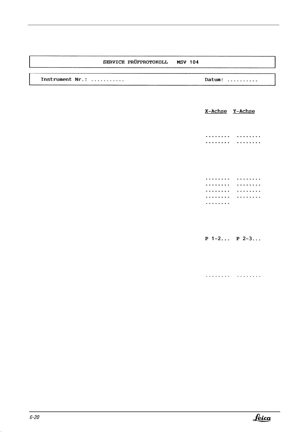
SERVICE PRÜFPLAN
1.
Spindel- und Laufwagenspiel:
MSV 104
Die Spindeln dürfen max. 0.lmm Längsspiel
aufweisen.
Längsspiel der Laufwagen, inklusive
Spindelspiel, darf max. 0.2mm betragen.
2. Funktionskontrolle der Endschalter:
Mit X- bzw.Y-Laufwagen bei max.
Geschwindigkeitsstufe in Endschalter
S2 und S4 fahren.
- Laufwagen müssen 3mm vor den
Mechanischen Anschlägen halten.
Kontrolle der Bewegungsrichtung.
Kontrolle der Mittelstellung
- Durch Druck auf den Rückstellknopf
muss die Kupplung aus jeder Stellung
in die Mittelposition zurückfahren.
Lampe im Rückstellknopf leuchtet auf.
Siehe SML Seiten
10-11
Siehe SML Seiten
Siehe SML Seiten
12-15
16-17
3.
Switch Board:
Die Brücke auf den Switch Boards
müssen wie Folgt gesteckt sein.
- X-Achse: Brücke Pin l/2
- Y-Achse: Brücke Pin 2/3
4.
Funktionsprüfung mit Steuergerät:
Geschwindigkeit min./max.
- Geschwindigkeitspotmeter auf Minimum
und Maximum drehen.
Alle Bewegungen müssen gleichmässig
und ratterfrei ablaufen.
Page 85
MSV104 Service Manual Stands/Stages
05/94 3691-DMF
1.
Spindel und Laufwagenspiel
Doc Code 556
913
2.
Funktionskontrolle der Endschalter
3.
Switch Board
4. Funktionsprüfung mit Steuergerät
Page 86

Service Manual Stands/Stages
Doc Code 556 913 05/94 3691-DMF
MSV104
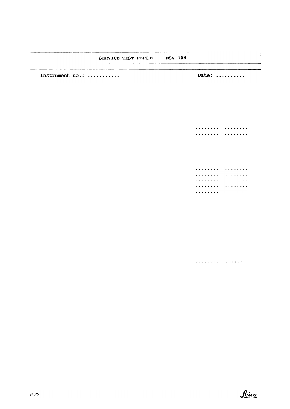
SERVICE INSPEKTION PROCEDURE
1.
Play of spindle and carriage:
MSV 104
The maximum permissible longitudinal
play of the spindles is 0.lmm.
The maximum permissible longitudinal
play of the carriages, including that
of the spindles, is 0.2mm.
2.
Function inspection of the end-switches:
Using X-
and Y-carriages respectively
and maximum speed step, travel to
end-stops S2 and S4.
- Carriages must stop 3mm before
mechanical stop.
Inspection of direction of movement
Inspection of mid-point
- When the resetting key is pressed,
the XY-unit must return to the mid-point
from any position.
The illuminated resetting key shines.
See SML pages l0-11
See SML pages 12-15
See SML pages 16-17
3.
Switchboard:
The bridges on the switchboard
must be connected as follows:
- X-axis:
- Y-axis:
4.
Function inspection with the control unit:
Bridge pin l/2
Bridge pin 2/3
Maximum and minimum speeds:
- Turn speed potentiometer to minimum
and maximum.
All movements must be uniform and
free of judder.
Page 87
MSV104
05/94 3691-DMF
1.
Play of spindles and carriages
Service Manual Stands/Stages
Doc Code 556 913
X-axis Y-axis
2.
Function inspection of end-switches
3.Switchboard
4.
Function inspection with control unit
P l-2...
P 2-3...
Page 88
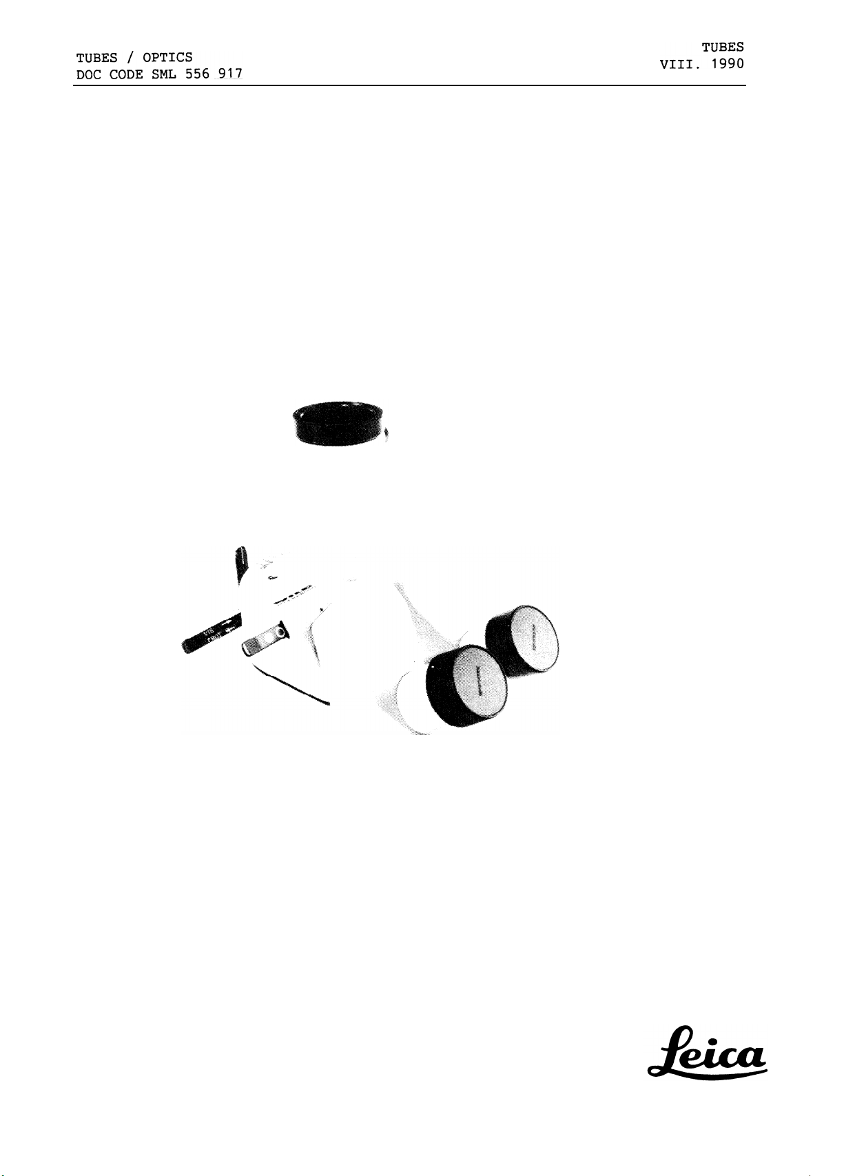
MTU 108 Trinokular Schrägtubus niedrig
MTU 108 Low inklined trinocular tube
SERVICE MANUAL
Edition VIII.1990
3691 Dmf
MTU 108/1
Page 89
TUBES
VIII. 1990
TUBES / OPTICS
DOC CODE SML 556 917
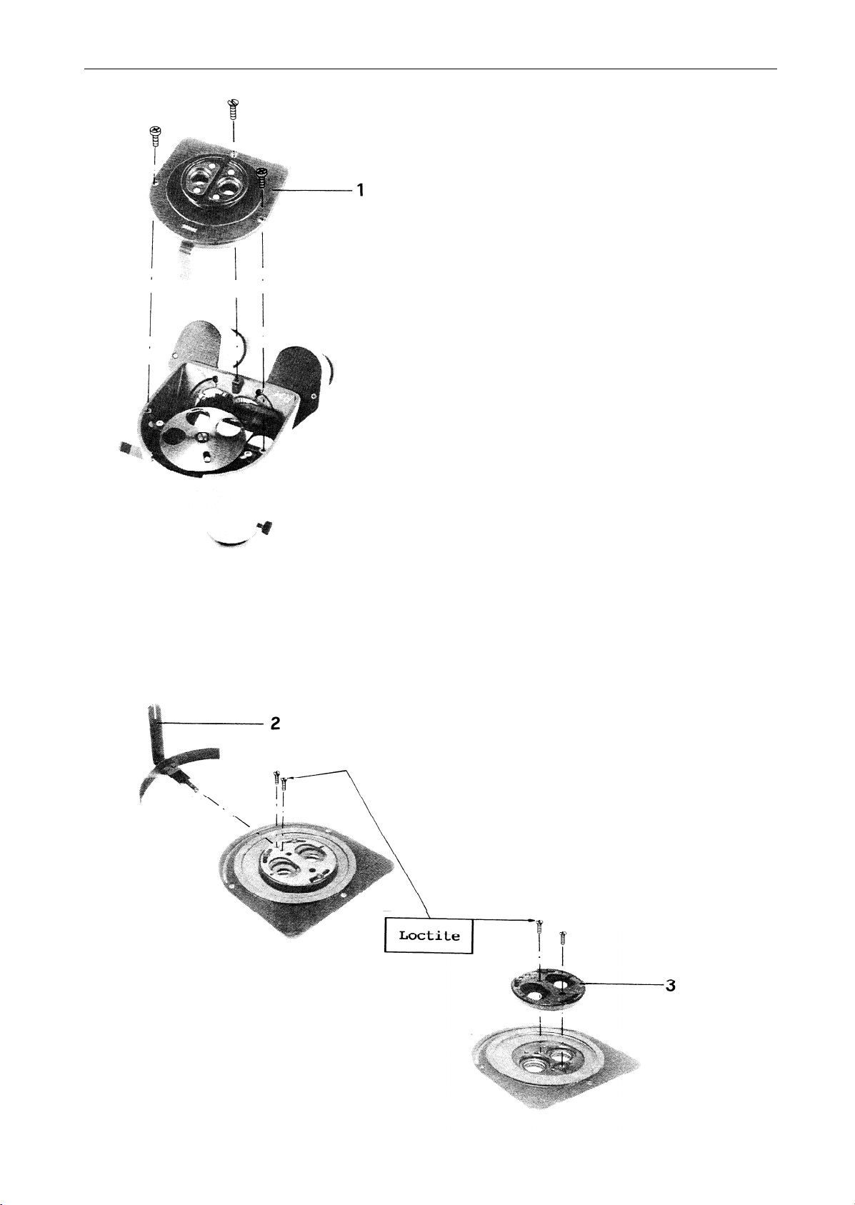
Ringschwalbe (l), demontieren.
Disassemble dovetail ring (1).
Blendenhebel (2) und Doppelirisblende
(3) demontieren.
Montage:
Senkschrauben mit Loctite sichern.
Disassemble diaphragm lever (2) and
double-iris diaphragm (3)
Assembly:
Secure countersunk screws using Loctite.
MTU 108/2
Page 90
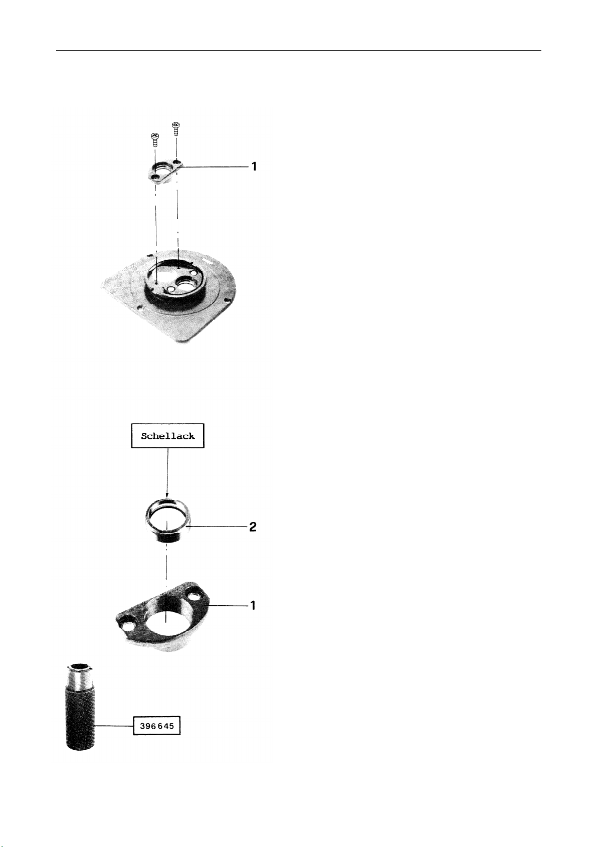
TUBES / OPTICS
DOC CODE SML 556 917
TUBES
VIII. 1990
Objektivfassung (1) demontieren,
Objektiv (2) aus Objektivfassung
schrauben.
Justierung:
Justierung siehe Seiten 14-17.
Disassemble objective mount (1) and
unscrew objective (2).
Adjustment:
See pages 14-17.
MTU 108/3
Page 91
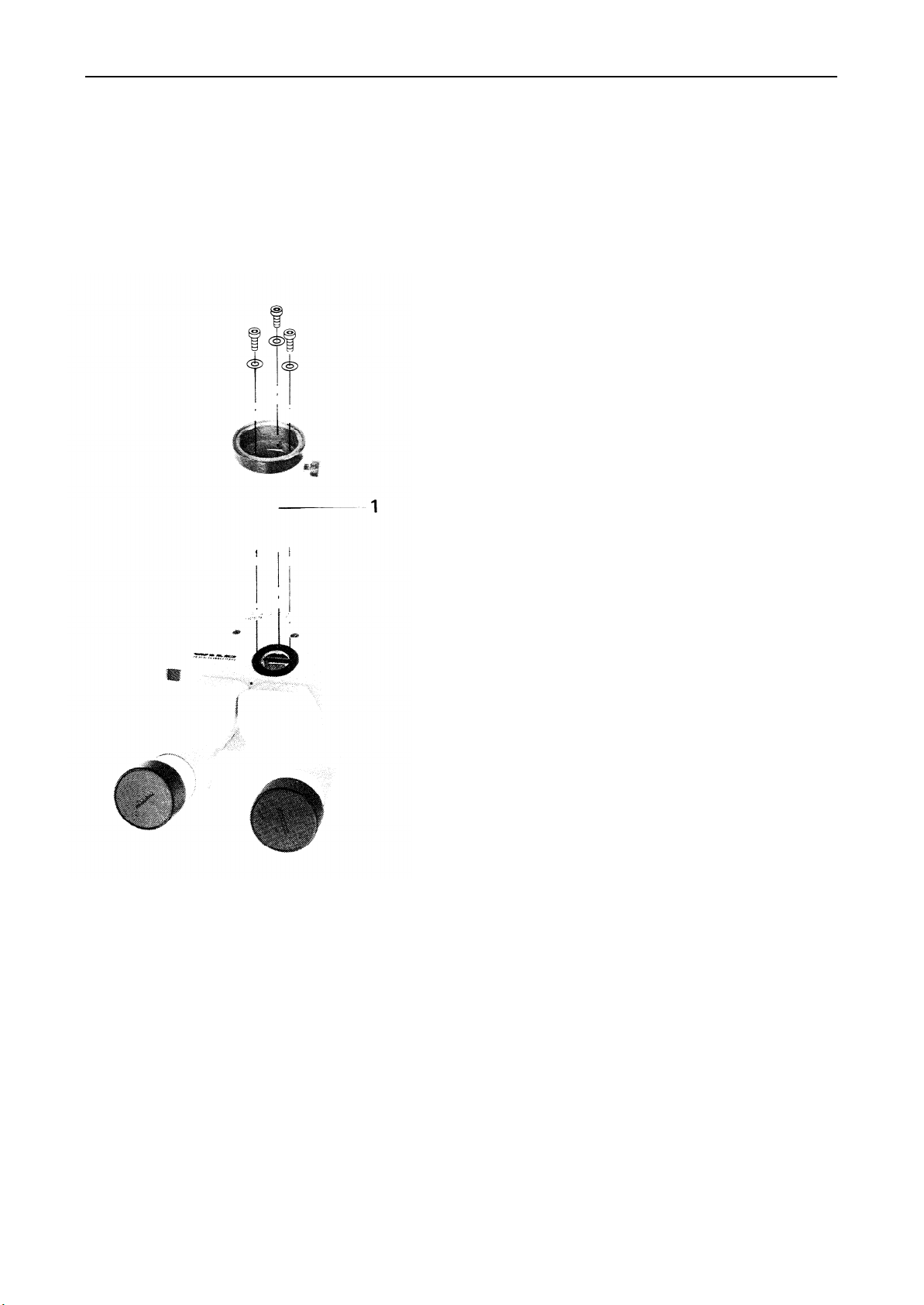
TUBES
VIII. 1990
TUBES / OPTICS
DOC CODE SML 556 917
Photorohr (1) demontieren.
Montage:
Lage der Klemmschraube (2) beachten.
Disassemble Phototube (1)
Assembly:
Note position of clamping screw (2).
MTU 108/4
Page 92
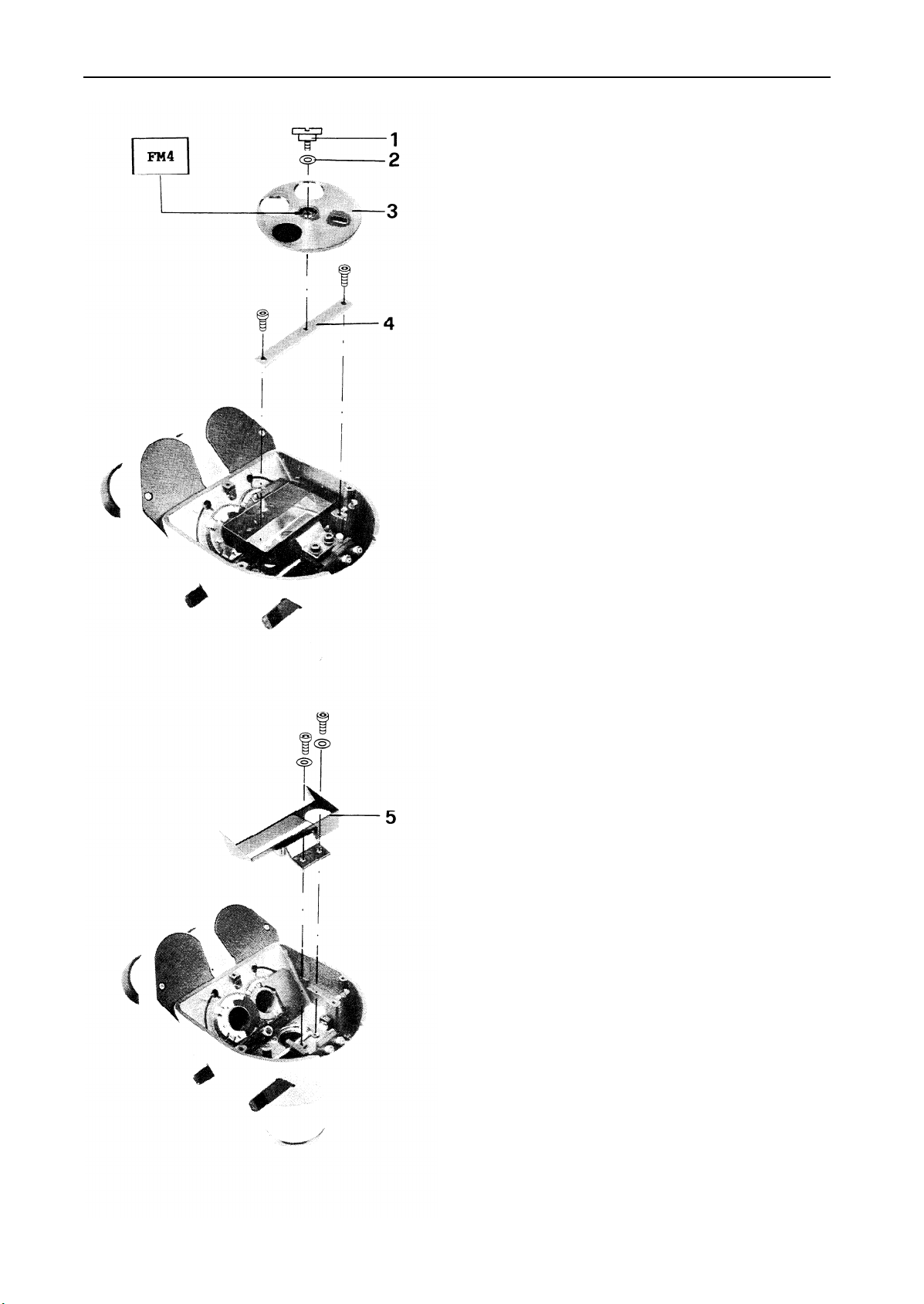
TUBES / OPTICS
DOC CODE SML 556 917
TUBES
VIII. 1990
Flachkopfschraube (l), Wellenfeder (2),
Drehscheibe (3) und Leiste (4)
demontieren.
Remove flat-headed screw (l), sinous
spring (2),
rotatable disk (3) and
batten (4).
Teilerprisma (5) demontieren.
Justierung:
Justierung siehe Seiten 10-11
Disassemble beam-splitting prism (5).
Adjusting:
See pages 10-11
MTU 108/5
Page 93
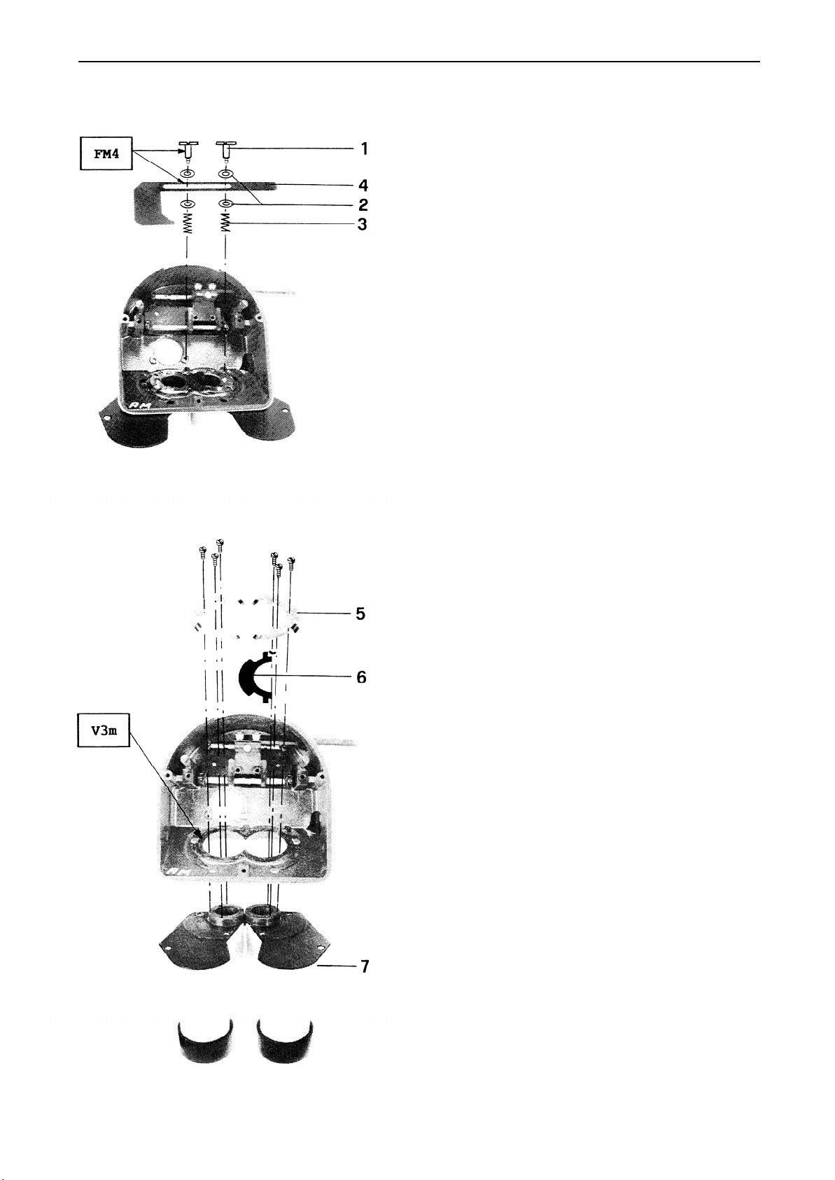
TUBES
VIII. 1990
TUBES / OPTICS
DOC CODE SML 556 917
Flachkopfschraube (l), Unterlagscheiben
(2), Feder (3) und Blende (4) demon-
tieren.
Remove flat-headed screw (l), washers
(2), springs (3) and baffle (4).
Federscheibe (5),
Lichtschutz (6) und
Prismagehäuse links und rechts (7)
demontieren.
Disassemble spring washers (5), light
stop 0,
and prism housing (7) on both
sides.
MTU 108/6
Page 94
TUBES / OPTICS
DOC CODE SML 556 917
VIII. 1990
TUBES
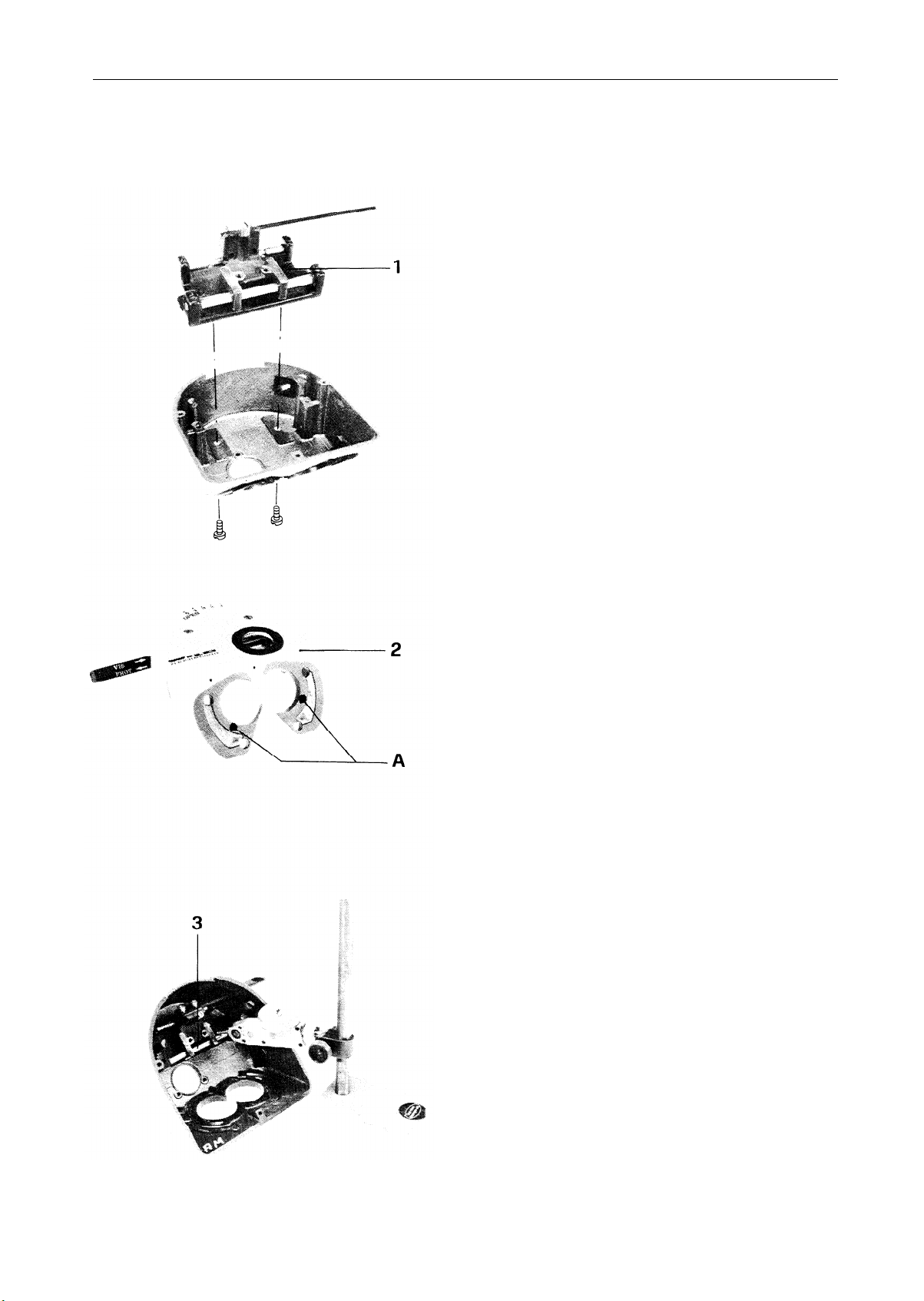
Führungsplatte mit Schlitten (1)
demontieren.
Montage:
Auflagefläche (A) reinigen, Gehäuse (2)
mit Auflagefläche auf Touchierplatte
drücken.
Führungsachse (3) zu Auflagefläche mit Pupitaster ausrichten.
Toleranz: 0.02mm
Disassemble guide plate together with
slide (1)
Assembly:
Clean contact surface (A). Press contact
surface of housing (2) against measuring
plate.
Align guide shaft (3) to contact
surface by means of gauge.
Tolerance: 0.02mm
MTU 108/7
Page 95
TUBES
VIII. 1990
TUBES / OPTICS
DOC CODE SML 556 917
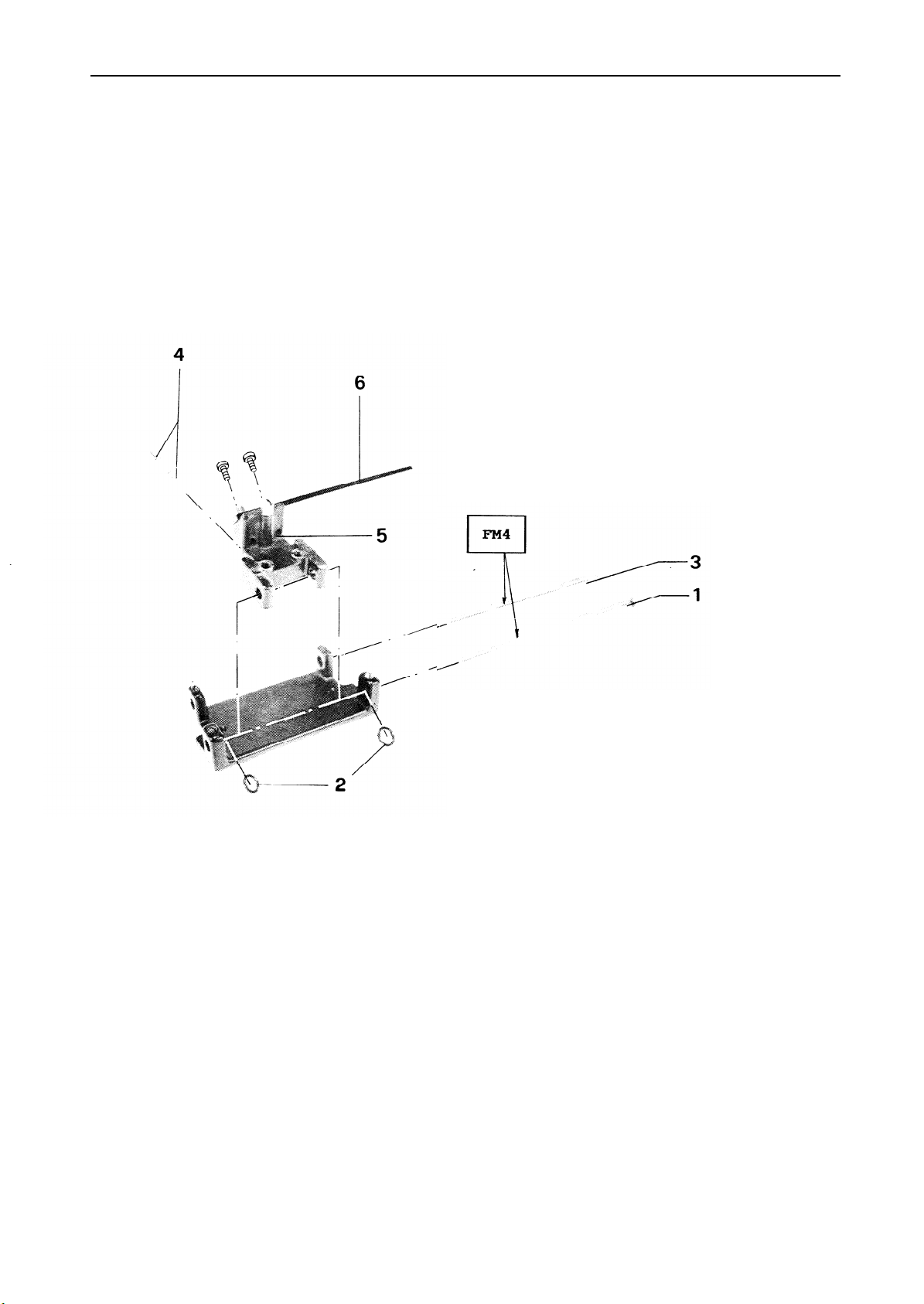
Führungsachse (l), O-Ringe (2),
Rastachse (3), Rastbolzen mit Feder (4)
Schlitten (5) und Zugstange (6) demontieren.
Achtung:
Schlitten und Führungsachse bilden
eine Schleifgruppe.
Disassemble guide shaft (l), O-rings
, ratchet shaft (3), ratchet bolt
(2)
with spring (4), slide (5) and
Connecting rod (6).
Note:
Slide and guide shaft are exactly
matched to one another.
MTU 108/8
Page 96
TUBES / OPTICS
DOC CODE SML 556 917
TUBES
VIII. 1990
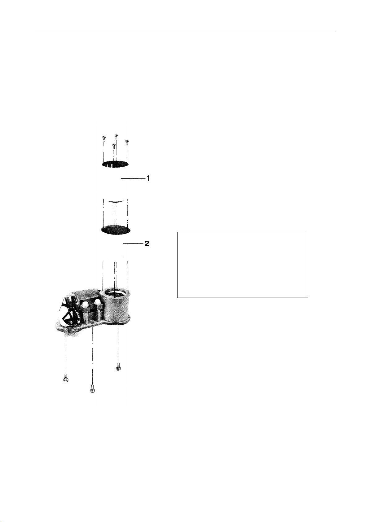
Okularrohr (1) und Abdeckhaube (2)
demontieren.
Remove eyepiece tube (1) and hood (2).
ACHTUNG:
Porroprisma nicht demontieren.
NOTE:
Do not disassemble Porro prism.
MTU 108/9
Page 97
TUBES
VIII. 1990
TUBES / OPTICS
DOC CODE SML 556 917
JUSTIERANLEITUNG
ADJUSTEMENT INSTRUCTIONS
MTU 108/10
Page 98

TUBES / OPTICS TUBES
DOC CODE SML 556 917
JUSTIEZANLEITUNG ADJUSTEMENT INSTRUCTIONS
VIII. 1990
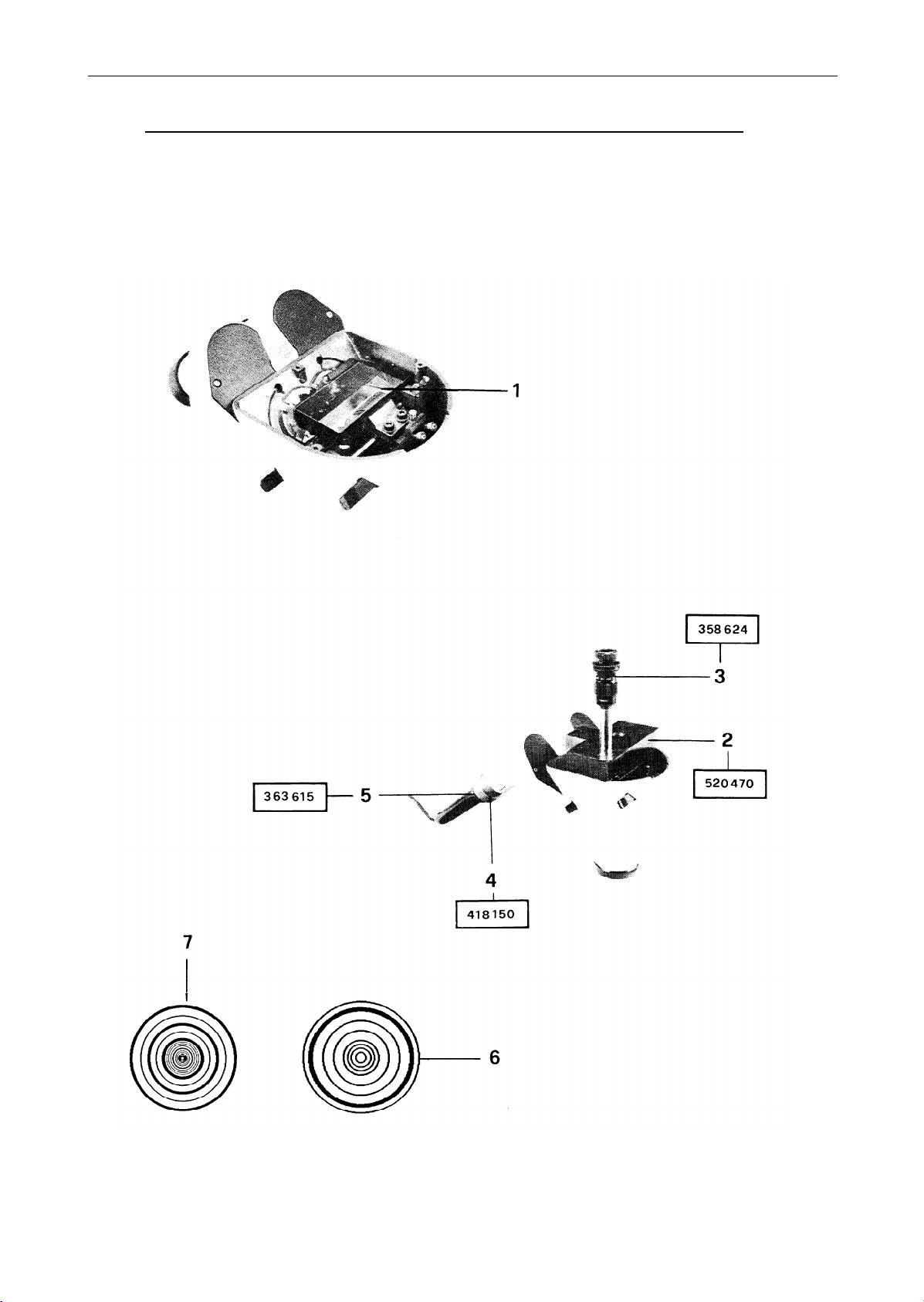
Teilerprisma (1) provisorisch montieren.
(3) an Gehäuseunterteil befestigen (1 Schraube).
Justiereinsatz (4) mit Fluchtkollimater (5) in Okularstutzen schieben.
Justierung:
Unendlich Bereich (6) des Fluchtkollimators anfokussieren. Durch Verschieben des
Teilerprisma,
kontrollieren.
Gängigkeit des Schlittens und der Ablauf des Fadenkreuzes prüfen.
Photorohrzentrierung prüfen, ev. nachjustieren. (Siehe Seite 18-19)
Toleranzen:
- Unendlich: 2 Kreise
- Endlich: 4 Kreise
- Ablauf der Strichplatte: max. 1 Strichstärke.
Fit beam Splitter prism (1) provisionally.
Straight-line setting telescope (3) to lower part of housing (1 screw).
Slide adjustment insert (4) and Straight-line setting collimator (5) into
eyepiece tube.
Adjustment:
Focus Straight-line setting collimator to 'infinite' range (6). By displacing
beam Splitter prism,
collimator. Verify using "finite" range (7).
Inspect smooth running of slide and displacement of crosshair.
Inspect centring of Phototube, readjusting if necessary (see pages 18-19).
Tolerances:
- "Infinite": 2 circles
- "Finite":
- Displacement of graticule: Maximum of one line thickness.
Fadenkreuz zu Fluchtkollimater zentrieren. Im Endlich Bereich (7)
centre crosshair in relation to Straight-line setting
4 circles
Justierplatte (2) mit Fluchtfernrohr
Secure adjustment plate (2) with
MTU 108/11
Page 99
TUBES
VIII. 1990
TUBES / OPTICS
DOC CODE SML 556 917
MTU 108/14
Page 100

TUBES / OPTICS TUBES
DOC CODE SML 556 917 VIII. 1990
Bildhöhe justieren:
Irisblende ganz öffnen,
(2) drücken.
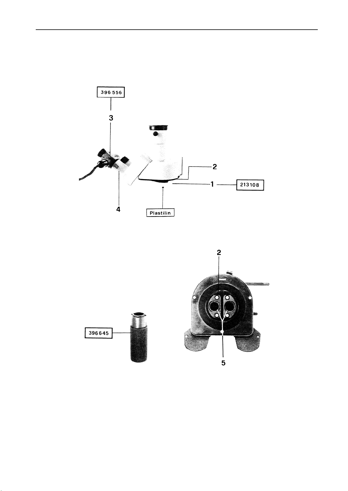
Autokollimationsokular (3) in Tubusrohr (4) stecken. Objektive (5)
ein- bzw. ausdrehen,
Spiegel (1) auf Plastilin legen, und gegen Ringschwalbe
Leuchtkreuz in der Strichplattenebene des Autokollimations-
okular scharf stellen.
Adjusting image height:
Open iris diaphragm completely.
press it against dovetail ring mount (2).
into eyepiece tube (4).
Turn objectives (5) in or out until luminous cross is
Place mirror (1) on a bed of plasticine, and
Insert autocollimation eyepiece (3)
sharply imaged in plane of graticule of autocollimation eyepiece.
MTU 108/15
 Loading...