

Page 1
Tel: +1 (301) 330-8811
Tel: +1 800 WILCOXON
Fax: +1 (301) 330-8873
www.wilcoxon.com
91457 Rev. C
Please read this manual thoroughly before making electrical connections and applying
power to the module. Following the instructions in this manual will ensure the transmitter
delivers optimum performance.
Newer versions of firmware may occasionally be released to address known bugs or add
new features. Make sure you always use the latest firmware version and product
documentation. Both can be found at www.wilcoxon.com.
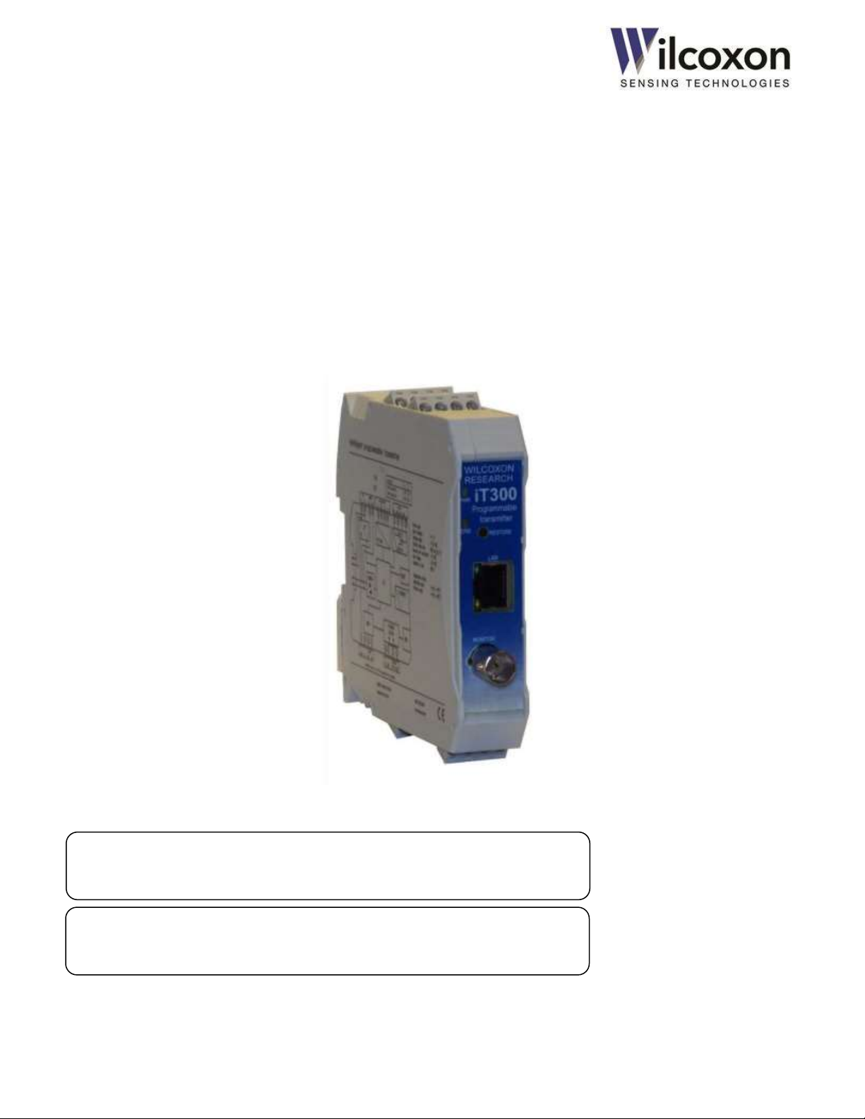
iT300 Series
Intelligent Configurable Transmitters
Installation and Operating Manual
Models iT300 and iT301
Wilcoxon Sensing Technologies
an Amphenol Company
Germantown, MD 20876 USA Page 1 of 59
Page 2

Tel: +1 (301) 330-8811
Tel: +1 800 WILCOXON
Fax: +1 (301) 330-8873
www.wilcoxon.com
91457 Rev. C
Table of Contents
1 Introduction ........................................................................................................................................ 7
2 Description .......................................................................................................................................... 7
3 Key features ........................................................................................................................................ 7
3.1 General features (all models) ...................................................................................................................................................7
3.2 iT301 advanced features ..........................................................................................................................................................7
4 Abbreviations used in this manual ...................................................................................................... 8
5 Safety Regulations and Installation Notes ........................................................................................... 8
5.1 Safety summary ........................................................................................................................................................................8
5.2 Declaration of conformity ........................................................................................................................................................8
6 iT300 family overview ......................................................................................................................... 9
7 System diagrams ................................................................................................................................. 9
7.1 Major system components ......................................................................................................................................................9
7.2 Basic circuit diagram .................................................................................................................................................................9
7.3 Isolation diagram ......................................................................................................................................................................9
8 Front panel LEDs ............................................................................................................................... 10
8.1 Operating modes ................................................................................................................................................................... 10
9 IO ports and signal assignments ........................................................................................................ 11
9.1 Terminal block locations and pin numbers ........................................................................................................................... 11
9.2 Terminal block pin and signal assignments .......................................................................................................................... 11
10 Electrical connections and wiring ...................................................................................................... 12
10.1 ESD precaution .................................................................................................................................................................. 12
10.2 Pluggable terminal blocks ................................................................................................................................................. 12
10.3 Sensor/transducer connections ....................................................................................................................................... 12
10.4 4-20 mA current loop connections ................................................................................................................................... 13
10.5 Dynamic output connections ........................................................................................................................................... 13
10.6 Signal relay connections (iT301) ....................................................................................................................................... 13
10.7 Power supply input connections ...................................................................................................................................... 13
10.8 Cable shielding and earth ground connections ............................................................................................................... 14
11 Power-up .......................................................................................................................................... 14
12 IO ports – detailed description .......................................................................................................... 15
12.1 Vibration sensor input ....................................................................................................................................................... 15
12.1.1 Constant current IEPE power source ........................................................................................................................... 15
12.1.2 BOV acceptable range and sensor fault detection ...................................................................................................... 15
12.2 Temperature sensor input ................................................................................................................................................ 16
12.3 4-20 mA current loop outputs .......................................................................................................................................... 16
12.3.1 Loop error state when sensor fault detected .............................................................................................................. 16
12.3.2 Loop force mode (test mode) ...................................................................................................................................... 16
12.4 Power supply input ........................................................................................................................................................... 16
12.5 BNC dynamic signal output............................................................................................................................................... 16
13 TBUS ................................................................................................................................................. 17
13.1 Stacking modules .............................................................................................................................................................. 17
13.2 Powering via the TBUS ...................................................................................................................................................... 17
Wilcoxon Sensing Technologies
an Amphenol Company
Germantown, MD 20876 USA Page 2 of 59
Page 3

Tel: +1 (301) 330-8811
Tel: +1 800 WILCOXON
Fax: +1 (301) 330-8873
www.wilcoxon.com
91457 Rev. C
14 DIN rail assembly and removal .......................................................................................................... 17
14.1 Requirements for installation ........................................................................................................................................... 17
14.2 DIN rail mounting .............................................................................................................................................................. 17
14.3 Preparing the DIN rail TBUS connectors........................................................................................................................... 18
14.4 Installing the module onto the DIN rail ............................................................................................................................ 18
14.5 Removing the module from the DIN rail .......................................................................................................................... 18
15 HTTP web server ............................................................................................................................... 19
15.1 10/100 Ethernet ................................................................................................................................................................ 19
15.2 Browser support ................................................................................................................................................................ 19
15.3 Establishing a network connection (PC, Laptop) ............................................................................................................. 19
15.3.1 Adjusting network adapter settings ............................................................................................................................. 20
15.4 Establishing a network connection .................................................................................................................................. 21
15.5 Accessing the web server ................................................................................................................................................. 21
16 User Interface (UI) ............................................................................................................................. 21
16.1 Overview ............................................................................................................................................................................ 21
16.2 Layout................................................................................................................................................................................. 21
16.3 Sample UI ........................................................................................................................................................................... 21
16.4 Configurable parameters .................................................................................................................................................. 24
16.5 Default configuration ........................................................................................................................................................ 24
17 Configuring the transmitter ............................................................................................................... 25
17.1 Access control .................................................................................................................................................................... 25
17.2 Restoring factory defaults ................................................................................................................................................. 25
17.3 Typical configuration flow ................................................................................................................................................. 25
17.4 Parameter interdependencies .......................................................................................................................................... 26
17.5 Highlighting of altered settings ......................................................................................................................................... 26
18 User-configurable parameters ........................................................................................................... 27
18.1 Machine information ........................................................................................................................................................ 27
18.2 Sensor input and averaging time ...................................................................................................................................... 27
18.2.1 Sensor type.................................................................................................................................................................... 27
18.2.2 Sensitivity ...................................................................................................................................................................... 27
18.2.3 Averaging time .............................................................................................................................................................. 27
18.2.4 Sensor power source .................................................................................................................................................... 27
18.2.5 Serial number ................................................................................................................................................................ 27
18.3 Frequency range ................................................................................................................................................................ 27
18.3.1 F
18.3.2 F
18.4 Processing bands ............................................................................................................................................................... 28
18.4.1 Output type ................................................................................................................................................................... 28
18.4.2 F
18.4.3 F
18.4.4 Detector type ................................................................................................................................................................ 28
18.5 True peak detection .......................................................................................................................................................... 29
18.5.1 Overview ....................................................................................................................................................................... 29
18.5.2 True peak detector response and decay times ........................................................................................................... 29
18.6 Measurement results ........................................................................................................................................................ 30
18.6.1 Vibration measurement results ................................................................................................................................... 30
18.6.2 Temperature measurement ......................................................................................................................................... 30
18.6.3 BOV monitor ................................................................................................................................................................. 30
................................................................................................................................................................................ 27
MAX
................................................................................................................................................................................. 27
MIN
............................................................................................................................................................................... 28
START
................................................................................................................................................................................ 28
STOP
Wilcoxon Sensing Technologies
an Amphenol Company
Germantown, MD 20876 USA Page 3 of 59
Page 4

Tel: +1 (301) 330-8811
Tel: +1 800 WILCOXON
Fax: +1 (301) 330-8873
www.wilcoxon.com
91457 Rev. C
18.7 4-20 mA current loops ...................................................................................................................................................... 30
18.7.1 Loop driving source ....................................................................................................................................................... 30
18.7.2 Loop full scale ................................................................................................................................................................ 31
18.7.3 Destination .................................................................................................................................................................... 31
18.7.4 Loop status .................................................................................................................................................................... 31
18.7.5 Testing the loops using force mode ............................................................................................................................. 31
18.8 Alerts and alarms (iT301) .................................................................................................................................................. 32
18.8.1 Overview ....................................................................................................................................................................... 32
18.8.2 Result status alerts ........................................................................................................................................................ 32
18.8.3 Alert limits ..................................................................................................................................................................... 32
18.8.4 Alarm Delay time .......................................................................................................................................................... 32
18.8.5 Alarm Hold time ............................................................................................................................................................ 33
18.8.6 Alarm Status .................................................................................................................................................................. 33
18.8.7 Clearing alarms ............................................................................................................................................................. 33
18.9 Signal relay (iT301) ............................................................................................................................................................ 33
18.9.1 Mapping alarms to the relay ........................................................................................................................................ 33
18.9.2 Testing the relay using force mode .............................................................................................................................. 33
18.9.3 Example – Alarm behavior ........................................................................................................................................... 34
19 User-action controls .......................................................................................................................... 35
19.1 Overview ............................................................................................................................................................................ 35
19.2 Saving the current configuration to a file ......................................................................................................................... 35
19.3 Loading a configuration from a file ................................................................................................................................... 35
19.4 Changing the user name and password ........................................................................................................................... 35
19.5 Restoring factory default settings ..................................................................................................................................... 36
19.6 Updating the module firmware ........................................................................................................................................ 36
20 Troubleshooting ................................................................................................................................ 37
20.1 Fault conditions ................................................................................................................................................................. 37
20.2 Unexpected behavior ........................................................................................................................................................ 37
21 Application example ......................................................................................................................... 39
22 Maintenance and calibration ............................................................................................................ 40
23 Warranty ........................................................................................................................................... 40
24 Technical assistance and customer service ........................................................................................ 40
24.1 Module information .......................................................................................................................................................... 40
24.2 Technical assistance........................................................................................................................................................... 40
24.3 Customer service ............................................................................................................................................................... 40
25 Accessories ....................................................................................................................................... 40
Appendix A: Technical data ........................................................................................................................ 41
Wilcoxon Sensing Technologies
an Amphenol Company
Germantown, MD 20876 USA Page 4 of 59
Page 5

Tel: +1 (301) 330-8811
Tel: +1 800 WILCOXON
Fax: +1 (301) 330-8873
www.wilcoxon.com
91457 Rev. C
Appendix B: Modbus (iT301) ..................................................................................................................... 44
Overview ......................................................................................................................................................................................... 44
Modbus-TCP ............................................................................................................................................................................... 44
RS485 serial interface modes .................................................................................................................................................... 44
RTU mode .............................................................................................................................................................................. 44
ASCII mode ............................................................................................................................................................................. 45
RS485 serial data bus ..................................................................................................................................................................... 45
RS485 connections ..................................................................................................................................................................... 45
Activating the RS485 termination resistor ................................................................................................................................ 46
Line Polarization ......................................................................................................................................................................... 47
RS485 serial interface configuration .............................................................................................................................................. 47
Slave address .............................................................................................................................................................................. 47
RTU/ASC II format ...................................................................................................................................................................... 47
Baud rate .................................................................................................................................................................................... 47
Parity ........................................................................................................................................................................................... 47
Stop bits ...................................................................................................................................................................................... 48
Object types .................................................................................................................................................................................... 48
Discrete Inputs ........................................................................................................................................................................... 48
Input Registers ............................................................................................................................................................................ 48
Holding Registers ........................................................................................................................................................................ 48
Function Codes ............................................................................................................................................................................... 48
02 - Read input status ................................................................................................................................................................ 48
03 - Read holding registers ........................................................................................................................................................ 48
04 - Read input registers ............................................................................................................................................................ 48
Data types ....................................................................................................................................................................................... 49
Boolean ....................................................................................................................................................................................... 49
Binary .......................................................................................................................................................................................... 49
Bitwise ........................................................................................................................................................................................ 49
ASCII ............................................................................................................................................................................................ 49
Floating point ............................................................................................................................................................................. 49
Byte ordering .................................................................................................................................................................................. 49
Examples – reading Modbus registers........................................................................................................................................... 50
Reading a discrete input ............................................................................................................................................................ 50
Reading discrete inputs.............................................................................................................................................................. 51
Reading input registers .............................................................................................................................................................. 51
Reading holding registers .......................................................................................................................................................... 52
Reading holding registers .......................................................................................................................................................... 52
Reading the module IP address ................................................................................................................................................. 53
Reading the module IP address via Modbus-TCP ..................................................................................................................... 54
RS485 Modbus troubleshooting guide.......................................................................................................................................... 55
Modbus Register tables.................................................................................................................................................................. 56
Discrete Inputs (1X references) - Alerts, Alarms, Status ........................................................................................................... 56
Input Registers (3X references) - Measurement results, module information ....................................................................... 56
Holding Registers (4X references) - User configurable parameters ......................................................................................... 57
Wilcoxon Sensing Technologies
an Amphenol Company
Germantown, MD 20876 USA Page 5 of 59
Page 6

Tel: +1 (301) 330-8811
Tel: +1 800 WILCOXON
Fax: +1 (301) 330-8873
www.wilcoxon.com
91457 Rev. C
Diagrams & Figures
Figure 1 - Major system components .................................................................................................................................................................9
Figure 2 - Basic circuit diagram ..........................................................................................................................................................................9
Figure 3 - Isolation diagram................................................................................................................................................................................9
Figure 4 - IO port and terminal block locations .............................................................................................................................................. 11
Figure 5 - Sensor connections .......................................................................................................................................................................... 12
Figure 6 - 4-20 mA current loop connections .................................................................................................................................................. 13
Figure 7 - Dynamic output connections .......................................................................................................................................................... 13
Figure 8 - Relay connections ............................................................................................................................................................................ 13
Figure 9 - Power supply connections ............................................................................................................................................................... 13
Figure 10 - Maximum input signal swing with 12V BOV................................................................................................................................ 15
Figure 11 - RC coupling circuit ......................................................................................................................................................................... 15
Figure 12 - Stacking modules ........................................................................................................................................................................... 17
Figure 13 - User Interface (1 of 2) .................................................................................................................................................................... 22
Figure 14 - True Peak detector behavior ......................................................................................................................................................... 29
Figure 15 - Effect of Alarm Delay and Hold times on alarm behavior ........................................................................................................... 34
Figure 16 - Application example ...................................................................................................................................................................... 39
Figure 17 - RS485 terminal block connections ................................................................................................................................................ 45
Figure 18 - RS485 TBUS terminal locations ..................................................................................................................................................... 45
Figure 19 - Proper RS485 terminations ........................................................................................................................................................... 46
Figure 20 - RS485 termination DIP switch location ........................................................................................................................................ 46
Figure 21 - Big endian byte ordering ............................................................................................................................................................... 49
Wilcoxon Sensing Technologies
an Amphenol Company
Germantown, MD 20876 USA Page 6 of 59
Page 7

Tel: +1 (301) 330-8811
Tel: +1 800 WILCOXON
Fax: +1 (301) 330-8873
www.wilcoxon.com
91457 Rev. C
1 Introduction
This document contains information on the installation,
configuration and operation of the iT300 Series of Intelligent
Transmitters. The vibration transmitters are designed and
manufactured in the USA by Wilcoxon Sensing Technologies,
Germantown, Maryland.
2 Description
The iT300 Series of configurable transmitter modules perform
acquisition and processing of dynamic vibration signals. The
transmitters are field configurable. Configurable parameters
include: input signal type, measurement bandwidth, detector
type, output type, English or metric measurement units, 4-20
mA driving source and full-scale range. Configuration may be
performed in the field, using a common web browser. No
custom or proprietary software is required. There are no
hardware jumpers to set.
The iT300/301 transmitters accept vibration signals from
piezoelectric (IEPE-type) accelerometers, piezovelocity
transducers (PVT™) and other sensors with comparable electrical
characteristics. They also feature an input for connection to a
Model 786T-type (or compatible) temperature sensor.
The iT300/301 transmitter module conditions, digitizes and
processes the input signal using powerful DSP technology. All
filtering, frequency selection, sub-sampling and power detection
is performed digitally, for consistent, reliable results. Selected
measurement results are then scaled and converted to dual 4-20
mA analog outputs. On iT301 models, measurement results and
operational status are also mapped to Modbus digital outputs.
iT300/301 transmitters are housed in a durable plastic enclosure
with a 35 mm DIN rail mount. The transmitter front panel
features multiple LEDs, a BNC connector for the buffered sensor
output, a “factory restore” push-button switch, and a standard
RJ45 jack for the Ethernet connection. The LEDs provide at-aglance operational status and indicate when power, sensor and
4-20 mA loops are correctly connected to the transmitter and
working properly. Removable, uniquely-keyed terminal blocks
allow for easy wiring and ensure correct terminal block
installation into the various transmitter IO ports.
3 Key features
3.1 General features (all models)
Field configurable via standard web browser
0.2 Hz – 20 kHz signal bandwidth (-3.0 dB, -0.1 dB)
20 V p-p sensor input range, >90 dB dynamic range
DSP signal processing with 1,600-line FFT
Built-in 4.5 mA constant current source for IEPE sensors
Buffered sensor output on the front-panel BNC connector
Buffered, dynamic signal outputs on terminal block
RMS, peak and peak-to-peak detection
Fast, true-peak detector for capturing short transients and
impulses
Dual, 4-20 mA active current loop outputs with diagnostic
test mode
Two configurable frequency bands
Digital acceleration-to-velocity or velocity-to-displacement
conversion, based on sensor type
Selectable English or metric measurement units
6-way isolated (500 VAC) IO ports to prevent ground loops
Wide, 11-32 VDC power supply input with reverse polarity
and transient protection
TBUS power and data buses
ESD and short circuit protection on all ports
Pluggable, individually-keyed terminal blocks with screw
terminals on all ports
Multiple front panel LED status indicators
Front panel factory restore switch
Auto-MDIX 10/100 Ethernet with HTTP web server
Field upgradable firmware
35 mm DIN rail mounting, stackable on TBUS
4-terminal wide (22.5 mm) modular housing
Wide operating temperature range of -40 °C to +70 °C
CE approvals, RoHS compliant
3.2 iT301 advanced features
Configurable alarms
Relay output with NO/NC contacts and test mode
Modbus over RS485
Modbus TCP over Ethernet
Wilcoxon Sensing Technologies
an Amphenol Company
Germantown, MD 20876 USA Page 7 of 59
Page 8

Tel: +1 (301) 330-8811
Tel: +1 800 WILCOXON
Fax: +1 (301) 330-8873
www.wilcoxon.com
91457 Rev. C
4 Abbreviations used in this manual
ASCII American Standard Code for Information Interchange
BOV Bias Output Voltage (DC)
BPS Bits Per Second
DCS Distributed Control System
DHCP Dynamic Host Configuration Protocol
DIN Deutsches Institut für Normung
DSP Digital Signal Processor/Processing
EMC Electromagnetic Compatibility
ESD Electrostatic Discharge
FFT Fast Fourier Transform
HTTP Hypertext Transfer Protocol
IEEE Institute of Electrical and Electronics Engineers
IEPE Integrated Electronics Piezo Electric
IO Input-Output
IPS Inches Per Second
LAN Local Area Network
LED Light Emitting Diode
mA milliamps
ms milliseconds
mV millivolts
MDIX Medium Dependent Interface Crossover
NC Normally closed
NO Normally open
PLC Programmable Logic Controller
RMS Root-mean-square
RoHS Restriction of Hazardous Substances Directive
RTU Remote Terminal Unit
SCADA Supervisory Control and Data Acquisition
SNR Signal-to-Noise-Ratio
UI User Interface
5 Safety Regulations and Installation
Notes
WARNING: This symbol indicates a caution or warning
that, if ignored, could cause damage to the product or connected
equipment.
This symbol indicates a technical tip or advice on operation
that provides helpful information on how to use or configure the
module.
WARNING: Risk of electric shock
During operation, certain parts of this device may carry
hazardous voltages. Disregarding this warning may result in
damage to equipment and/or serious personal injury.
Provide a switch/circuit breaker close to the device, which is
labeled as the disconnect device for this device or the entire
control cabinet.
Provide overcurrent protection (I ≤ 6 A) in the installation.
Disconnect the device from all power sources during
maintenance work and configuration (the device can remain
connected to SELV or PELV circuits).
5.1 Safety summary
Because this product is designed to be used in an industrial
environment, personnel involved with the installation,
operation and maintenance of this instrument should be
familiar with all plant safety requirements before using this
product. Only qualified personnel should perform
installation and service.
The transmitter must not be opened. There are no user
serviceable parts within the product. Do not attempt to
repair or modify the module. Replace the module only with
an equivalent device.
The IP20 ingress protection rating (IEC 60529/EN 60529)
implies the module is intended for installation and use only
in a clean and dry environment. The module must not be
subjected to stresses or thermal conditions which exceed
the specified limits.
The device is not designed for use in atmospheres with a
danger of dust explosions. If dust is present, the module
must be installed within an approved housing, whereby the
surface temperature of the housing must be taken into
consideration.
Use common sense and avoid haste during installation and
operation of this product.
5.2 Declaration of conformity
This product complies with the standards for:
Electrical safety according to EN61010-1
Limits and methods of measurement of radio
disturbance characteristics
Limits for harmonic current emissions
RoHS Directive, 2011/65/EU
Wilcoxon Sensing Technologies
an Amphenol Company
Germantown, MD 20876 USA Page 8 of 59
Page 9
Tel: +1 (301) 330-8811
Tel: +1 800 WILCOXON
Fax: +1 (301) 330-8873
www.wilcoxon.com
91457 Rev. C
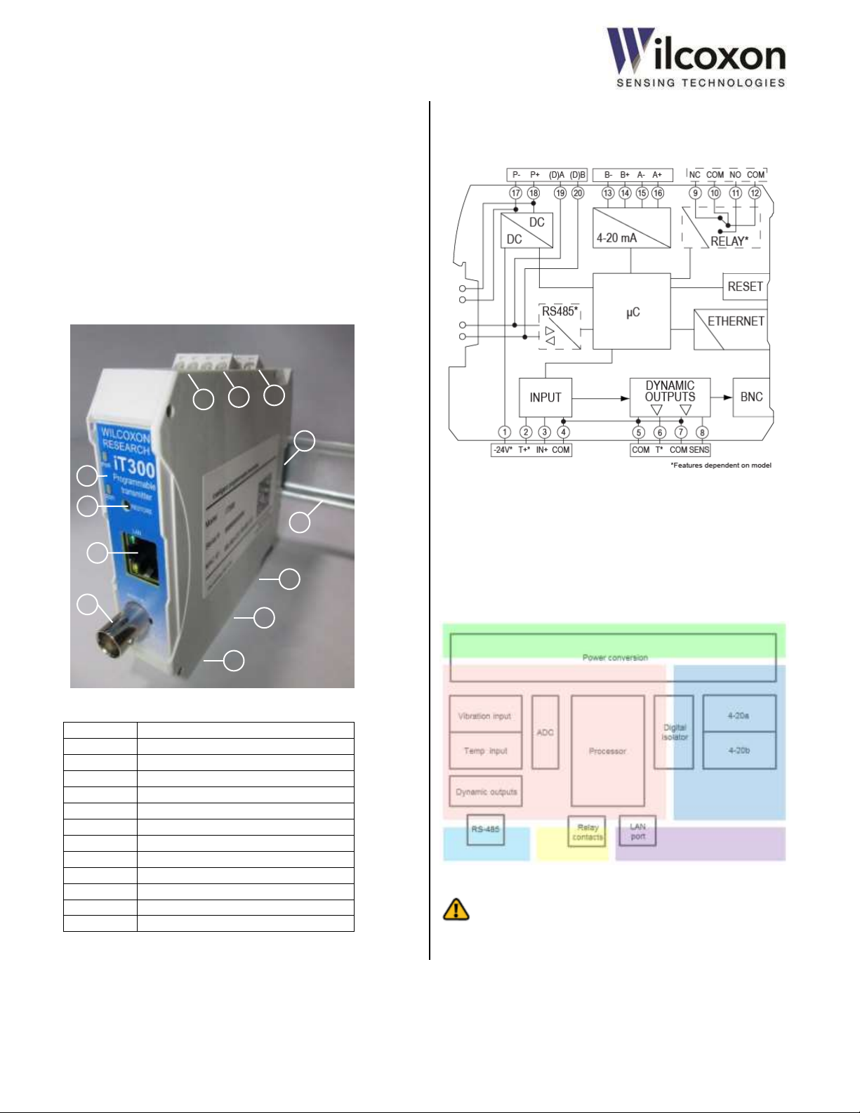
#
Description
1
Sensor/transducer inputs
2
(Empty)
3
Buffered, dynamic outputs
4
Signal relay contacts*
5
4-20 mA current loop outputs
6
Power input / RS485 serial interface*
7
LED indicators
8
Factory restore / alarm clear button
9
Ethernet connection
10
Buffered sensor output BNC connection
11
TBUS card-edge connector
12
DIN rail
8
12 3 4
2
1
7
9
10
11
5
6
6 iT300 family overview
iT300 Base model. Accepts input from IEPE
accelerometers or velocity transducers.
Temperature sensor input.
iT301 Same as iT300, but adds: alarm capability, signal
relay output, Modbus over RS485, Modbus-TCP.
7 System diagrams
7.1 Major system components
Figure 1 - Major system components
7.2 Basic circuit diagram
Shown below are the major functional blocks of the transmitter.
Figure 2 - Basic circuit diagram
7.3 Isolation diagram
The transmitter features 500 VAC functional isolation between
six zones: 1.) power input, 2.) sensor input, 3.) 4-20 mA outputs,
4.) Ethernet-LAN, 5.) RS485, 6.) signal relay. Figure 3 shows the
isolation zones.
*iT301 only
Wilcoxon Sensing Technologies
an Amphenol Company
Germantown, MD 20876 USA Page 9 of 59
Figure 3 - Isolation diagram
CAUTION! Functional or operational isolation is necessary
only for the correct functioning of the product. It does not
protect or isolate against electrical shock.
Page 10

Tel: +1 (301) 330-8811
Tel: +1 800 WILCOXON
Fax: +1 (301) 330-8873
www.wilcoxon.com
91457 Rev. C
8 Front panel LEDs
8.1 Operating modes
Multiple LEDs, located on the front panel, indicate the module’s
operating modes.
PWR
The green PWR LED indicates power and test mode status.
OFF Unit not powered
ON Normal operating mode
BLINKING One or more test modes active (4-20 mA
loops or signal relay)
RLY (iT301)
The yellow RLY LED indicates the relay status.
OFF Relay not energized
(NO contacts = open, NC contacts = closed)
ON Relay energized
(NO contacts = closed, NC contacts = open)
ERR
The red ERR LED indicates system and connection faults.
OFF No faults – normal operation
ON Sensor fault (priority)
BLINKING 4-20 mA loop fault
See section 20 “Troubleshooting” for information about
correcting fault conditions.
RS485 (iT301)
The yellow RS485 LED indicates RS485 data activity.
OFF Non-matching address/RS485 idle
FLASH RS485 Modbus packet with matching slave
address received
The RS485 LED will flash each time the module receives a
Modbus packet that contains a matching slave address. Data
packets not addressed to the module are ignored and do not
cause LED activity.
Ethernet Status
Green and yellow LEDs, located on the RJ45 jack, provide status
of the Ethernet interface.
Yellow (Link speed)
OFF 10 Mbps
ON 100 Mbps
Green (Link/activity)
OFF No link
ON Link established (blinks with link activity)
Wilcoxon Sensing Technologies
an Amphenol Company
Germantown, MD 20876 USA Page 10 of 59
Page 11

Tel: +1 (301) 330-8811
Tel: +1 800 WILCOXON
Fax: +1 (301) 330-8873
www.wilcoxon.com
91457 Rev. C
IO Port
Terminal numbers and
signal assignments
Vibration sensor
1 – No connection
2 – Temperature sensor in (T+)
3 – Signal in / Sensor Power (IN+)
4 – Circuit Common (COM)
Temperature
dynamic output
5 – Circuit Common (COM)
6 – Temperature out (T)
Sensor dynamic output
7 – Circuit Common (COM)
8 – Sensor out (SENS)
Signal relay*
9 – Normally closed (NC)
10 – Relay common (COM)
11 – Normally open (NO)
12 – Relay common (COM)
4-20 mA Loop B
13 – B14 – B+
4-20 mA Loop A
15 – A16 – A+
Power input
17 – P18 – P+
RS485*
19 – (D)A
20 – (D)B
SENSOR IN
PWR
RLY
ERR
RS485
CLR / RESTORE
DYNAMIC OUT
5 8 6
7
1 4 2
3
12 9 11
10
16
13
15
14
20
17
19
18
SIGNAL RELAY*
CURRENT LOOPS
RS485* / POWER INPUT
WILCOXON
iT301
P+
P-
(D)A*
(D)B*
REAR
FRONT
FRONT
REAR
MIDDLE
TBUS
ETHERNET
MONITOR
9 IO ports and signal assignments
9.1 Terminal block locations and pin numbers
*iT301 only
Figure 4 - IO port and terminal block locations
9.2 Terminal block pin and signal assignments
* iT301 only
Table 1 - Terminal numbers and signal assignments
Wilcoxon Sensing Technologies
an Amphenol Company
Germantown, MD 20876 USA Page 11 of 59
Page 12
Tel: +1 (301) 330-8811
Tel: +1 800 WILCOXON
Fax: +1 (301) 330-8873
www.wilcoxon.com
91457 Rev. C
Sensor
Signal Out/Power in (A)
Common (B)
Temperature out (C)
iT300/301
(3) Signal in/Sensor power
(4) Common
(2) Temperature in
10 Electrical connections and wiring
10.1 ESD precaution
CAUTION! electrostatic discharge
Although the transmitter contains ESD suppression devices on all
IO ports, components still can be damaged or destroyed by large
magnitude electrostatic discharge. When handling the module or
making electrical connections, observe the necessary safety
precautions against ESD according to EN 61340-5-1 and IEC
61340-5-1. This will reduce the possibility of damage caused by
ESD.
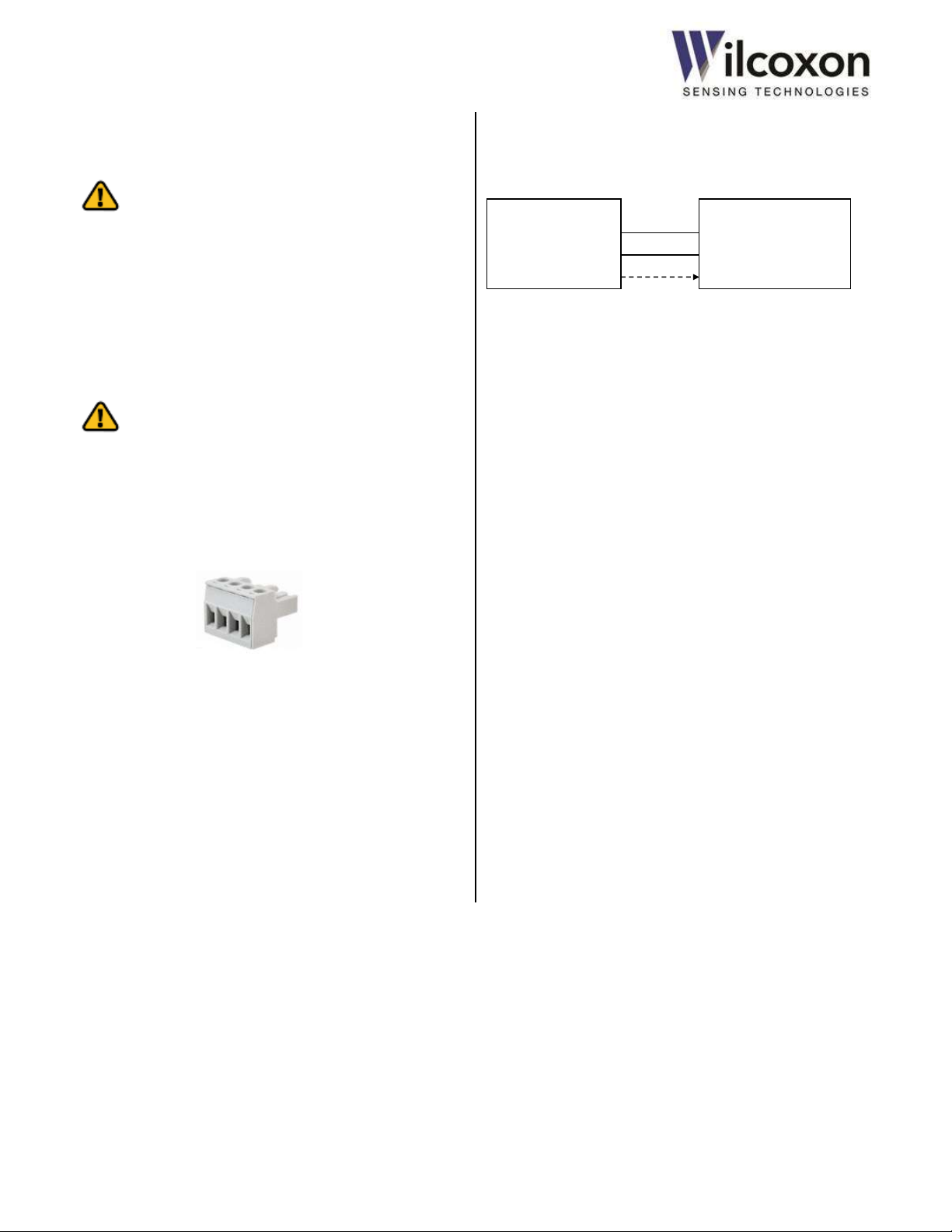
10.2 Pluggable terminal blocks
CAUTION! Electrical connections should not be made
with power applied to the module.
All electrical connections to the transmitter are made using
pluggable terminal blocks. The removable terminal blocks have
screw terminals for easy wiring and are uniquely keyed to ensure
correct installation into the various transmitter IO ports.
10.3 Sensor/transducer connections
Connect the IEPE vibration sensor as shown in ”Figure 5 - Sensor
connections”.
Figure 5 - Sensor connections
A 786T accelerometer with a temperature output utilizes the
temperature input on terminal #2. The temperature portion of
the sensor is powered by the accelerometer circuit.
Note: Connection of a temperature sensor is optional.
The terminal blocks accept 12 AWG through 24 AWG size wire
(cable cross section: 0.2...2.5 mm²).
To make a connection to a terminal block:
1. Strip wire to 0.25” (6.4 mm)
2. Optionally, install a ferrule onto the wire and crimp securely
3. Insert the wire into the terminal block
4. Use a flat-blade screwdriver to tighten the screw to a torque
of 0.6 Nm (2.1 oz/in)
Wilcoxon Sensing Technologies
an Amphenol Company
Germantown, MD 20876 USA Page 12 of 59
Page 13
Tel: +1 (301) 330-8811
Tel: +1 800 WILCOXON
Fax: +1 (301) 330-8873
www.wilcoxon.com
91457 Rev. C
iT300/301
(16) LOOP A OUT+
(15) LOOP A OUT−
(14) LOOP B OUT+
(13) LOOP B OUT−
PLC, DCS, etc
(9) NC
(10) COM
(11) NO
(12) COM
Monitoring Equipment
(8) SENS OUT
(7) COM
(6) TEMP OUT
(5) COM
Monitoring Equipment
Power Supply
24 VDC+
COM
iT300/301
(18) P+
(17) P−
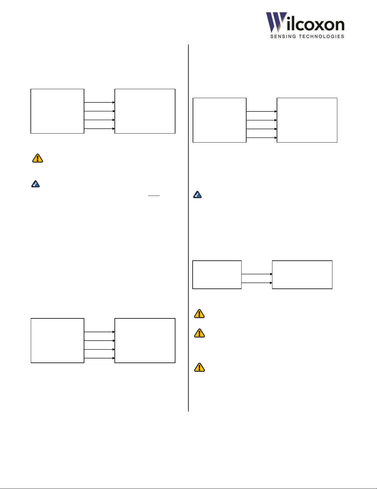
10.4 4-20 mA current loop connections
Route the Loop A and Loop B 4-20 mA outputs to a compatible
monitoring system as shown, being careful to use a properly
sized load resistor. The transmitter sources the voltage and
current for both loops.
Figure 6 - 4-20 mA current loop connections
Caution: The 4-20 mA outputs will not work with
externally powered loops.
Tech tip! If a 4−20 mA output is not required by the
application or is to remain unconnected, the loop must be
disabled, via the UI, to prevent a current loop fault from being
indicated by the transmitter. By default, Loop A is enabled and
Loop B is disabled. See section 18.7, “4-20 mA current loops” for
information on how to configure the current loop outputs.
10.5 Dynamic output connections
A buffered, unfiltered version of the AC vibration sensor signal,
riding on the BOV, is available as a terminal block output. This
output is in parallel with the front-panel BNC connector.
A buffered and low-pass-filtered version of temperature sensor
signal is also available as a terminal block output.
All dynamic outputs are short circuit protected and have a 50 Ω
output impedance.
iT300/301
Figure 7 - Dynamic output connections
10.6 Signal relay connections (iT301)
A mechanical relay provides both normally open (NO) and
normally closed (NC) contacts on a single terminal block.
The contacts can be wired to the monitoring equipment, as
required by the application. The operation of the relay is
configured via the UI.
iT301
Figure 8 - Relay connections
The relay contacts are rated 30 volts DC, 2A and are electrically
isolated from all other internal circuits.
Tech tip! The relay “COM” terminals are simply the center
pole of the relay contacts. They are not connected to any other
circuit “common.”
10.7 Power supply input connections
Connect a 24-volt DC (11 – 32 volts, allowable) power source to
the power input terminals, as shown. Optionally, the module
may be powered via the TBUS.
Figure 9 - Power supply connections
WARNING: The supply voltage must not exceed 33 volts or
damage to the module may occur.
WARNING: The maximum current handling capacity of the
power supply input terminals is 4 amps. When using these
terminals to supply power to the TBUS, do not exceed the 4-amp
rating.
WARNING: The iT300 TBUS is NOT compatible with older
Wilcoxon Research iT100/200, iT401 or iT501 series modules.
When connecting modules via the TBUS, connect only iT300
series modules together on the same bus. Do not connect any
other types of modules or devices to an iT300 TBUS. Doing so
may result in damage to the modules.
Wilcoxon Sensing Technologies
an Amphenol Company
Germantown, MD 20876 USA Page 13 of 59
Page 14

Tel: +1 (301) 330-8811
Tel: +1 800 WILCOXON
Fax: +1 (301) 330-8873
www.wilcoxon.com
91457 Rev. C
10.8 Cable shielding and earth ground connections
Shielding and proper earth grounding are important for the
mitigation of interference and proper operation of the
transmitter. A good shield connection prevents egress of
transmitted signals and ingress of interfering sources. Faulty
shield connections, along with the presence of external sources
of interference, can adversely affect signal integrity. Ensure all
cable shields are properly terminated and connected correctly, as
required by the application.
There is no “shield” or earth ground connection on the
transmitter module. Cable shields should be properly connected
to protective earth (PE) ground external to the transmitter, as
called for by the application. For best electrical performance,
cable shields should be terminated as close as possible to the
transmitter.
Wilcoxon provides enclosures with integrated grounding bus
bars that are located in proximity with the DIN rail. The bus bar
should be connected to a central earthing point using short, lowimpedance connections with a large surface area.
To facilitate connecting cable shields to earth ground, DIN-mount
shield connection clamps and grounding terminal blocks are
available from Wilcoxon. See section 25, “Accessories” for a
complete list of items to complement the installation and
operation of the transmitter.
The type of shield connection should be determined by the
expected operating environment:
Connecting the shield at only one equipment end works to
suppress interference caused by electrical fields.
Connecting the shield at both equipment ends works to
suppress interference caused by dynamic magnetic
fields. When connecting the shield at both ends, the
possibility of ground loops must be considered; galvanic
disturbances along the reference potential can interfere
with the signal, thereby reducing the effectiveness of the
shielding.
11 Power-up
After all wires are connected, power can be applied to the
module. The module begins its power-up sequence immediately
after power is applied. There is no on-off switch.
During power-up, all front-panel LED indicators will illuminate for
three seconds while a self-check is performed. After the unit has
completed its self-check, the green PWR LED will remain on. If
the transmitter passes its self-test and the sensor and primary 420 mA loop are connected correctly, the red ERR LED will be off.
See section 8, “Front panel LEDs” for detailed explanation of
LEDs and unit operating status.
Wilcoxon Sensing Technologies
an Amphenol Company
Germantown, MD 20876 USA Page 14 of 59
Page 15
Tel: +1 (301) 330-8811
Tel: +1 800 WILCOXON
Fax: +1 (301) 330-8873
www.wilcoxon.com
91457 Rev. C
Capacitance
-3dB frequency
10 µF
6 Hz
47 µF
1.2 Hz
100 µF
0.6 Hz
330 µF
0.2 Hz
12 IO ports – detailed description
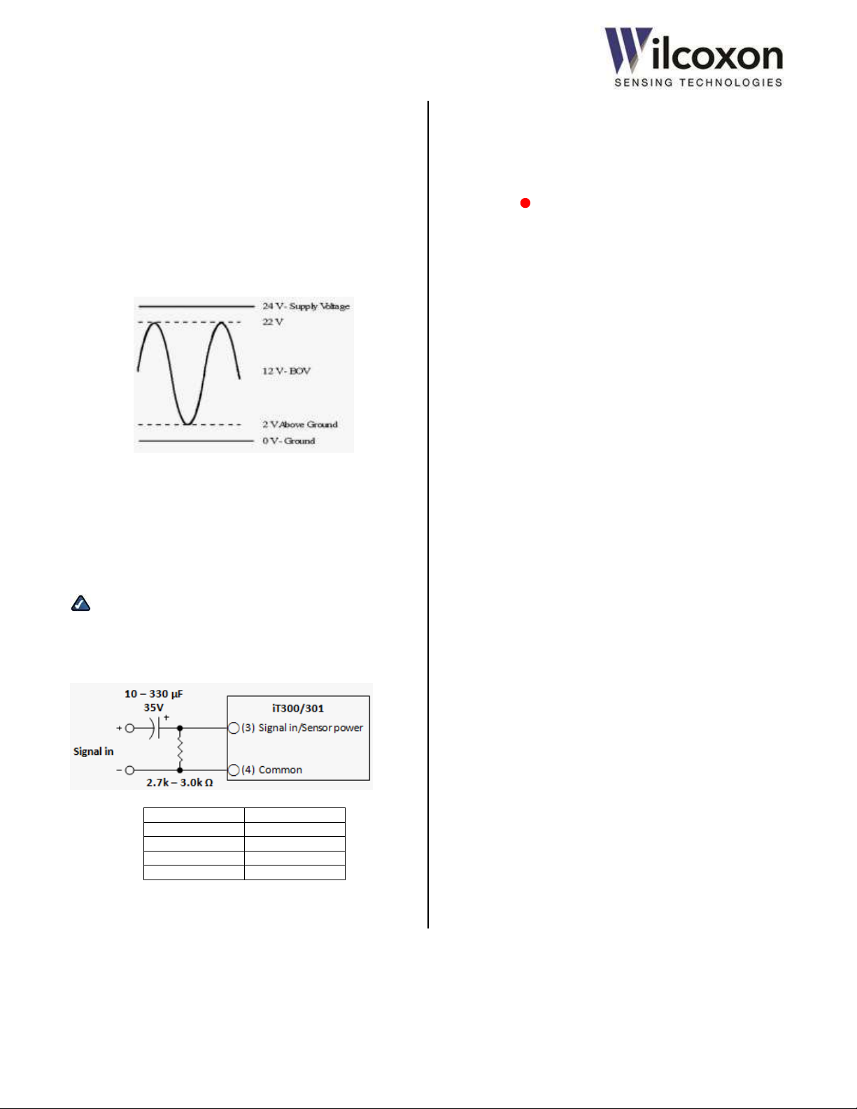
12.1 Vibration sensor input
The transmitter has been designed to accept signals from
piezoelectric (IEPE-type) accelerometers, velocity transducers
and other compatible sensors that have a BOV of approximately
12 volts. This allows the maximum input signal swing without
clipping. If the BOV deviates significantly from 12 volts, the
maximum allowable input signal swing and dynamic range will
be reduced accordingly. The analog input circuitry is powered by
+24 VDC.
Figure 10 - Maximum input signal swing with 12V BOV
12.1.1 Constant current IEPE power source
12.1.2 BOV acceptable range and sensor fault detection
The module continuously monitors and reports the BOV of the
sensor signal. If the DC level falls outside the acceptable range, a
sensor fault will be indicated. When a sensor fault is detected,
the UI will display “Fault” next to the BOV reading and the front-
panel ERR LED will illuminate. A sensor fault will cause the 4-
20 mA loop current to be set to 2 mA on each enabled loop. A
loop current of less than 4 mA conveys the fault condition to the
4-20 mA monitoring equipment. This complies with NAMUR
NE43.
For the iT300, the acceptable range for the BOV is 5 to 16 volts
and is not user adjustable. For the iT301, the acceptable range
for the sensor BOV can be adjusted via UI.
If a sensor fault is indicated, the sensor BOV should be checked
with an isolated (hand-held) DC voltmeter at the BNC connector
and verified it is within the acceptable range. The BOV is also
displayed on the UI. See section 20, ”Troubleshooting” for more
information on sensor faults.
The built-in current source (IEPE Power) is enabled by default
and supplies a nominal 4.5 mA to the attached sensor. The
current source can be disabled, via the UI, to allow the
connection of an external voltage.
Tech tip! In all cases, the input signal must have a DC bias of
at least +5.5 volts. Signal sources not compliant with this
requirement can use the biasing circuit shown below. If more
information is required, contact Wilcoxon technical support.
Figure 11 - RC coupling circuit
Wilcoxon Sensing Technologies
an Amphenol Company
Germantown, MD 20876 USA Page 15 of 59
Page 16
Tel: +1 (301) 330-8811
Tel: +1 800 WILCOXON
Fax: +1 (301) 330-8873
www.wilcoxon.com
91457 Rev. C
12.2 Temperature sensor input
The transmitter supports a 786T-type (or similar) accelerometer
with temperature sensor with a sensitivity of 10 mV/°C. The
input range for the temperature signal is 0 VDC to +1.2 VDC.
Before being passed to the processing circuitry and dynamic
output terminals, the temperature input signal is low-pass
filtered to remove noise and high frequency content.
Connection of a temperature sensor is optional. If a temperature
sensor is not connected, the transmitter will read a temperature
of approximately 0 °C (32 °F).
12.3 4-20 mA current loop outputs
The transmitter provides two analog, 4-20 mA current loop
outputs. The outputs are usually wired to a Programmable Logic
Controller (PLC) or a Distributed Control System (DCS). The loop
current is proportional to the measurement result that is
mapped as the loop driving source. Measurement results
(process variables) are mapped to the current loops via the UI.
Both current loop outputs are “active.” That is, the outputs
source the voltage and current for the loops and are designed to
be connected to a passive, resistive load. The total loop
resistance, including the load resistor, should not exceed 500 Ω.
If the loop resistance is too high or if an output is unconnected, a
loop fault will be detected by the module. When a loop fault is
detected, “Fault” will be displayed in the Level (mA) field on the
UI and the ERR LED on the front panel will blink. If a loop is
not needed in the application or is to remain unconnected, it
should be disabled via the UI. Disabling the loop will set the
current to 0 mA and prevent a loop fault from being indicated.
By default, the primary loop (Loop A) is enabled and the
secondary loop (Loop B) is disabled. These settings may be
changed via the UI.
Loop compliance voltage is 15 volts, ±5%. The current loop
outputs are electrically isolated from all other internal circuitry
and are protected from short circuits.
Caution: The 4-20 mA outputs will not work with
externally powered loops.
12.3.1 Loop error state when sensor fault detected
The transmitter complies with Namur NE43 recommendations
for indicating a sensor fault to a control system by means of the
4-20 mA signal. If the transmitter detects a fault with the
vibration sensor input, the current in the enabled loops will be
set to 2 mA. This conveys the condition of a sensor fault to the 420 mA monitoring equipment. See section 12.1.2, “BOV
acceptable range and sensor fault detection”.
12.3.2 Loop force mode (test mode)
A loop test function is provided to allow loop current to be
forced to any value between zero and 20 mA. This feature
permits testing of the loops and receiving equipment using
various, user-defined currents. When either loop is placed in test
mode, a green indicator on the UI and the PWR LED on
the front panel will both blink. Test mode is controlled via the UI.
See section 18.7.5 for details.
12.4 Power supply input
A 24-volt DC power source is normally used to power the
transmitter. To provide greater installation flexibility, the power
source voltage may range from 11 volts to 32 volts DC. This
allows the use of power supplies with outputs other than 24
volts. The power inputs are protected from a reverse polarity
condition and are electrically isolated from all other internal
circuitry.
WARNING: The power supply voltage must not exceed 33
volts or damage to the module may occur.
WARNING: The maximum current handling capacity of the
power supply input terminals is 4 amps. When using these
terminals to supply power to the TBUS, do not exceed the 4-amp
rating.
12.5 BNC dynamic signal output
A buffered sensor output is available on the front-panel BNC
connector. This allows live, on-line signal analysis and testing of
the sensor. This analog output is a buffered version of the raw,
unfiltered sensor signal allowing full spectrum analysis.
The BNC output is short circuit protected and has an output
impedance of 50 Ω.
Note: When connecting a portable data collector or online
monitoring system to the dynamic outputs the external meter’s
internal constant current source, if so equipped, should be
turned off. Failure to do so may result in a corrupted waveform.
Wilcoxon Sensing Technologies
an Amphenol Company
Germantown, MD 20876 USA Page 16 of 59
Page 17
Tel: +1 (301) 330-8811
Tel: +1 800 WILCOXON
Fax: +1 (301) 330-8873
www.wilcoxon.com
91457 Rev. C
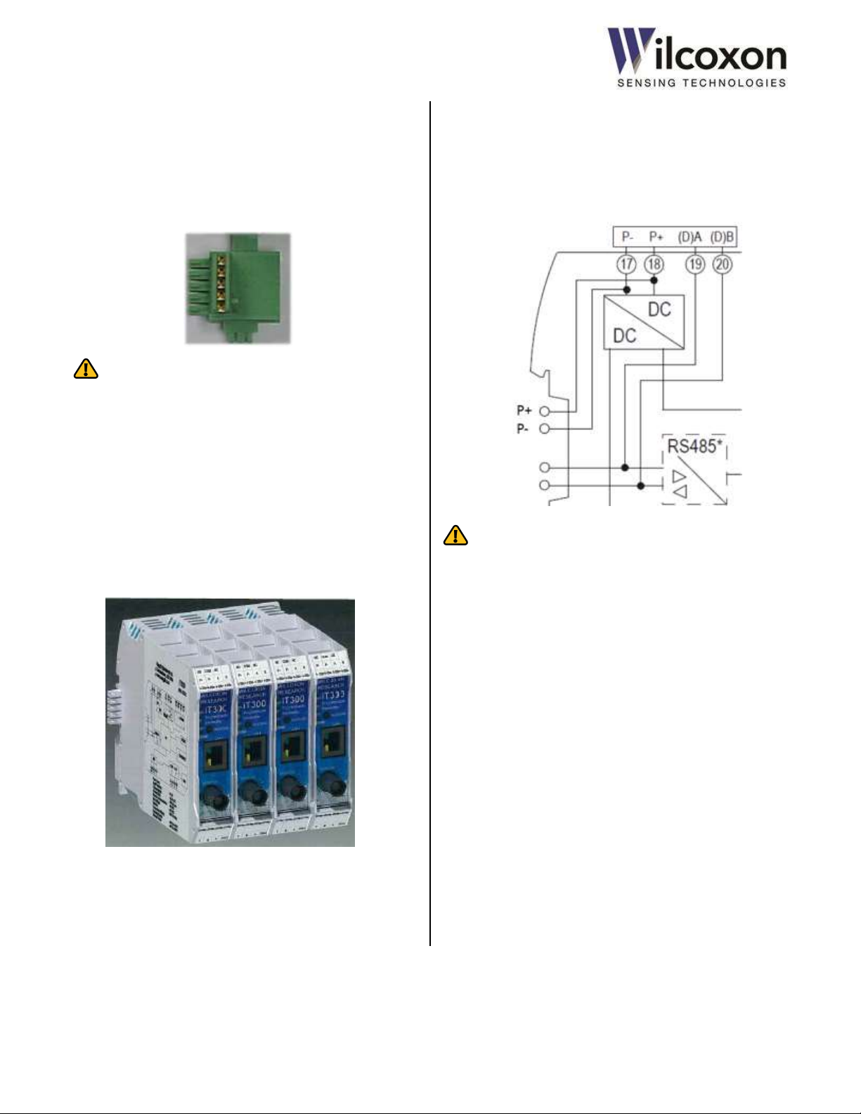
13 TBUS
The TBUS allows multiple modules to be interconnected without
the need for external wiring. Connection to the TBUS is made via
a recessed board-edge connector, located on the rear of the
module, and a IT032 connector. The board-edge fingers plug
directly into the connector.
WARNING: The iT300 TBUS is NOT compatible with older
iT100/200, iT401 or iT501 series modules. When connecting
modules via the TBUS, connect only iT300 series modules
together on the same bus. Do not connect any other types of
modules or devices to an iT300 TBUS. Doing so may result in
damage to the modules.
13.1 Stacking modules
Multiple modules can be connected together through the TBUS.
This allows power to be supplied to all modules on the bus. For
iT301 models, the RS485 serial interface is also available on the
TBUS.
Figure 12 - Stacking modules
13.2 Powering via the TBUS
Power can be bused to all modules via shared P+ and P- supply
rails on the TBUS card-edge connector. This allows one module
to supply power to other modules on the bus. The location of
the terminal is shown below. The positive TBUS terminal (P+) is
nearest the power input terminal block.
WARNING: The maximum current handling capacity of the
power supply input terminals is 4 amps. When using these
terminals to supply power to the TBUS, ensure the 4 amp rating
is not exceeded.
14 DIN rail assembly and removal
14.1 Requirements for installation
To protect the module from harsh conditions, it is recommended
to install the unit in a suitable enclosure (NEMA 4 type, or
equivalent) with the appropriate degree of environmental
protection. In all cases, the enclosure must meet the
requirements of the installation.
14.2 DIN rail mounting
The iT300 Series of modules are designed to mount to a
standard 35 mm DIN rail. The rear of the module has a springloaded metal foot catch that holds the module securely in place.
The module is installed onto the rail by simply snapping it into
place.
Each module is 22.5 mm wide and therefore occupies 22.5 mm
of DIN rail space.
Wilcoxon Sensing Technologies
an Amphenol Company
Germantown, MD 20876 USA Page 17 of 59
Page 18
Tel: +1 (301) 330-8811
Tel: +1 800 WILCOXON
Fax: +1 (301) 330-8873
www.wilcoxon.com
91457 Rev. C
14.3 Preparing the DIN rail TBUS connectors
Connect the required number of connectors by pushing them
together, as shown.
Attach the connectors to the DIN rail by hooking the latch of the
connectors over the top of the rail and then snapping the
bottom of the connectors onto the rail.
The completed connector assembly on the rail.
14.4 Installing the module onto the DIN rail
With the module tilted up, as shown, hook the top lip of the
module onto the top of the rail while carefully aligning the DIN
rail connector with the card edge slot on the rear of the module.
Gently push the module downward and toward the rail. Firmly
seat the module so the DIN TBUS connector fully engages the
module card edge connector. The metal foot catch should
audibly snap onto the rail. The module is now mechanically
secured to the rail.
WARNING: The iT300 TBUS is NOT compatible with older
iT100/200, iT401 and iT501 series modules. When connecting
modules via the TBUS, connect only iT300 series modules
together on the same bus. Do not connect any other types of
modules or devices to an iT300 TBUS. Doing so may result in
damage to the modules.
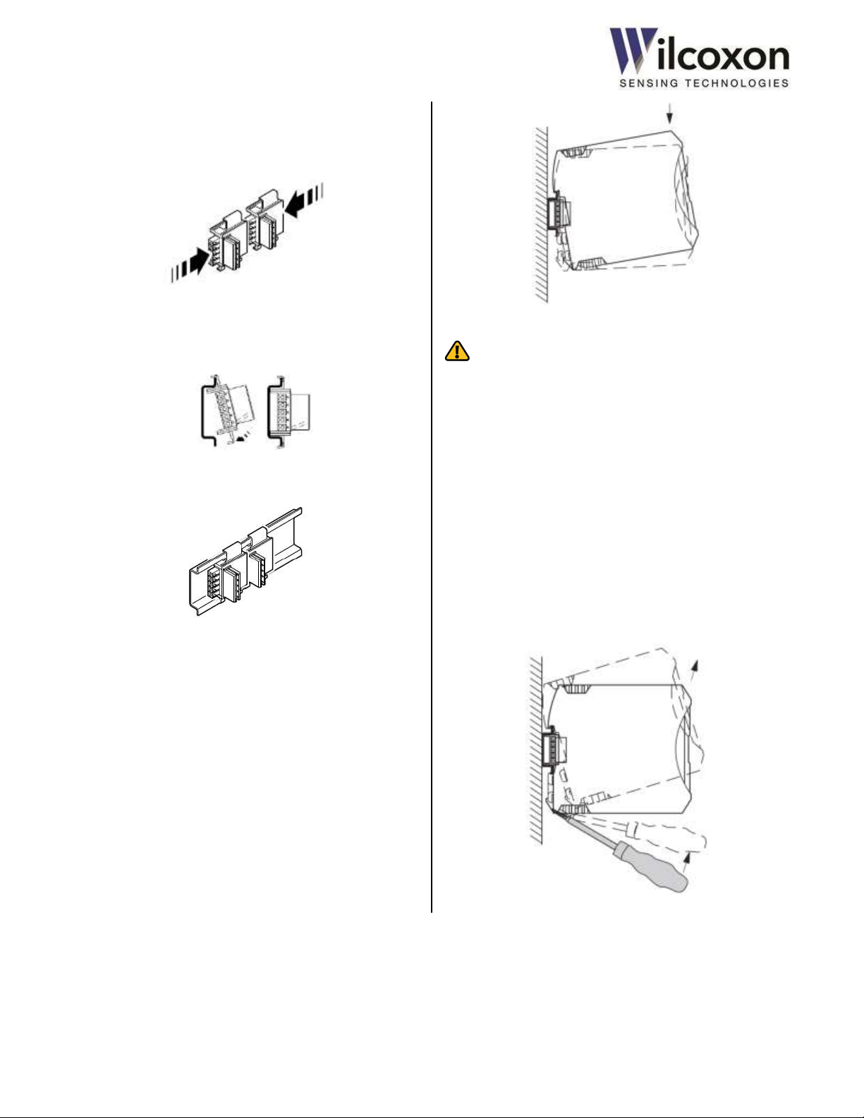
14.5 Removing the module from the DIN rail
Locate the metal foot catch on the bottom rear of the module.
The catch is spring loaded. To remove the module from the rail,
insert a small, flat-blade screwdriver or other suitable tool into
the foot catch slot. (The blade must be less than ¼ inch (6 mm)
in width to fit into the slot on the latch.) Using the screwdriver as
a lever, gently push the screwdriver upward, as shown, to release
the locking mechanism. With the catch released, tilt the module
upward and remove it from the rail and connector.
Wilcoxon Sensing Technologies
an Amphenol Company
Germantown, MD 20876 USA Page 18 of 59
Page 19

Tel: +1 (301) 330-8811
Tel: +1 800 WILCOXON
Fax: +1 (301) 330-8873
www.wilcoxon.com
91457 Rev. C
15 HTTP web server
The transmitter is field-configurable via a built-in HTTP web
server. The server features an intuitive, easy-to-use, one-page
interface that can be accessed with any modern web browser.
No custom or proprietary software is required.
15.1 10/100 Ethernet
Connection to a 10/100 Ethernet device or network is made via a
standard RJ45 connector located on the front panel of the unit.
To eliminate cabling complications, the Ethernet transceiver
utilizes an Auto-MDIX function to detect the type of cable being
used (straight-through or crossover). The transceiver will
automatically swap the transmit and receive pairs, as necessary,
to ensure the proper transmission and reception of data in
accordance with IEEE 802.3 auto-negotiation and crossover
specifications.
The transmitter supports four different Ethernet protocols: 10
Mb/s Half Duplex, 10 Mb/s Full Duplex, 100 Mb/s Half Duplex,
and 100 Mb/s Full Duplex. The transceiver is configured for
Auto-Negotiation. The Auto-Negotiation function provides a
mechanism for exchanging configuration information between
two ends of a link segment to automatically select the highest
performance mode of operation supported by both devices. It
ensures that the highest performance protocol will be selected
based on the advertised ability of the Link Partner (the Ethernet
device connected to the transmitter).
If the Link Partner does not support Auto-Negotiation or it has
been administratively disabled, the transmitter still can
determine and match speed with the Link Partner. However, the
presence of full duplex cannot be detected, so the transmitter
will default to half duplex. In this case, the Link Partner should
also be configured for half duplex operation.
For optimum performance, the Link Partner should have AutoNegotiation enabled.
For further details regarding Auto-Negotiation, refer to Clause 28
of the IEEE 802.3u specification.
15.2 Browser support
The following browsers are supported and have been verified
compatible with the web server:
Mozilla Firefox
Microsoft Internet Explorer
Google Chrome
The most recent version of each browser, at time of firmware
release, has been tested. As newer firmware revisions are
released, additional browser support may be added. Visit
www.wilcoxon.com for the latest firmware revision and
downloads.
CAUTION! Proper functionality and operability cannot be
guaranteed with older versions of the supported browsers or
browsers not listed.
15.3 Establishing a network connection (PC, Laptop)
iT300 series modules support the Internet Protocol version 4
(IPv4) network addressing architecture. The default IPv4
network settings are as follows:
IP address 192.168.0.100
Subnet mask 255.255.255.0
Default gateway 192.168.0.1
Only static IP addressing is permitted. The module does not
support DHCP.
To establish a connection between the iT300/301 and a
standalone PC or laptop computer, the computer’s network
settings will, most likely, need to be adjusted. The IPv4
connection must be configured by disabling DHCP (if enabled)
and manually entering the IP address and subnet mask. This is
because the PC must belong to the same subnet as the
iT300/301 and have the same network prefix. The prefix
occupies the most-significant bits of the address. In this case,
the prefix is 192.168.0.
If the networking settings are not correct, communication with
the transmitter will not be possible. An example of how to
configure the network settings on a PC running the Windows
operating system is presented in the next section.
Wilcoxon Sensing Technologies
an Amphenol Company
Germantown, MD 20876 USA Page 19 of 59
Page 20

Tel: +1 (301) 330-8811
Tel: +1 800 WILCOXON
Fax: +1 (301) 330-8873
www.wilcoxon.com
91457 Rev. C
15.3.1 Adjusting network adapter settings
In the following example, we will adjust a PC’s network adapter
settings to be compatible with the iT300/301. The operating
system is Windows 7. The procedure will differ for other
operating systems. Consult a network administrator if you are
unsure about making changes to network settings.
To adjust the network adapter settings:
Open the Control Panel and access the Network and Sharing
Center. Then click on Change Adapter Settings:
If more than one network adapter or LAN connection is
available, choose the desired connection which to modify. In this
example, we will modify Local Area Connection 2:
After selecting the desired network connection to modify, click
Properties:
Select Internet Protocol Version 4 (TCP/IPv4) and then click
Properties.
Wilcoxon Sensing Technologies
an Amphenol Company
Germantown, MD 20876 USA Page 20 of 59
Page 21

Tel: +1 (301) 330-8811
Tel: +1 800 WILCOXON
Fax: +1 (301) 330-8873
www.wilcoxon.com
91457 Rev. C
Select “Use the following IP address:”
Change the IP address to 192.168.0.1.
Change the Subnet mask to 255.255.255.0.
The Default gateway field should be left blank.
NOTE: Enabling ‘Use the following IP address’ will disable your
PC from communicating with other networks.
Save the changes by clicking “OK.”
15.4 Establishing a network connection
The transmitter also may be accessed via a LAN or other
network. If the module is intended to be connected to a
network, consult the network administrator to obtain
information regarding the proper network settings.
15.5 Accessing the web server
16 User Interface (UI)
16.1 Overview
The transmitter is field-configurable via the built-in web server
and User Interface (UI). The UI allows configuration to be
performed in the field or from a remote location, using any
common web browser.
16.2 Layout
For simplicity and ease-of-use, the UI consists of a single web
page. The layout of the page positions the various fields in an
intuitive, logical order. Configurable parameters are grouped into
nine sections:
1. Machine Information
2. Sensor Input Configuration
3. Frequency Range
4. Band Configuration
5. Measurement Results and Alarms
6. 4-20 mA Loops
7. Network Configuration
8. Modbus/RS485
9. User-action Controls.
In addition to allowing configuration of the transmitter, the UI
also displays all measurement results and current status in real
time.
16.3 Sample UI
A representative sample of the iT301 User Interface is shown in
Figure 13. Actual page layout will vary by model.
After ensuring the network settings of the Link Partner are
correct, a connection to the web server can be established.
To access the web server, launch the web browser on your
computer and enter the module’s IP address
(default is 192.168.0.100) in the Address field. Then, press Enter.
Upon establishing a connection to the web server, the User
Interface (UI) is displayed.
Wilcoxon Sensing Technologies
an Amphenol Company
Germantown, MD 20876 USA Page 21 of 59
Page 22
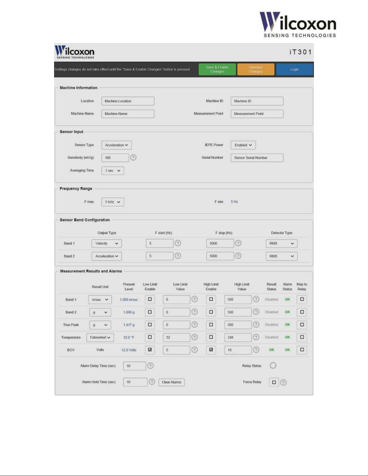
Tel: +1 (301) 330-8811
Tel: +1 800 WILCOXON
Fax: +1 (301) 330-8873
www.wilcoxon.com
91457 Rev. C
Figure 13 - User Interface (1 of 2)
Wilcoxon Sensing Technologies
an Amphenol Company
Germantown, MD 20876 USA Page 22 of 59
Page 23

Tel: +1 (301) 330-8811
Tel: +1 800 WILCOXON
Fax: +1 (301) 330-8873
www.wilcoxon.com
91457 Rev. C
User interface (continued)
Wilcoxon Sensing Technologies
an Amphenol Company
Germantown, MD 20876 USA Page 23 of 59
Page 24

Tel: +1 (301) 330-8811
Tel: +1 800 WILCOXON
Fax: +1 (301) 330-8873
www.wilcoxon.com
91457 Rev. C
Factory Default Configuration
Username
user
Password
admin
IP address
192.168.0.100
Subnet mask
255.255.255.0
Default gateway
192.168.0.1
Sensor type
Accelerometer
Sensor sensitivity
100 mV/g
Averaging time
1 second
IEPE power source
Enabled
F
MAX
(Highest measurable frequency)
5 kHz
F
MIN
(Lowest measurable frequency)
5 Hz
Band 1 passband
5 Hz - 5 kHz
Band 1 output type
Velocity (ips)
Band 1 detector type
RMS
Band 2 passband
5 Hz - 5 kHz
Band 2 output type
Acceleration (g)
Band 2 detector type
RMS
4-20 mA Loop A
Enabled
Loop A source variable
Band 1
Loop A full-scale output
5 ips
4-20 mA Loop B
Disabled
Alarms*
Disabled1
Signal relay*
Disabled
Modbus over serial RS485*
Format
RTU
Slave address
1
Baud rate
9600
Parity
None
16.4 Configurable parameters
Machine information
Machine location (Free text)
Machine name (Free text)
Machine ID (Free text)
Measurement point (Free text)
Sensor input
Sensor type (Selection)
Sensor sensitivity (User entry)
Sensor serial number (Free text)
Averaging time (Selection)
IEPE power enabled/disabled (Selection)
Measurement frequency range
F
Sensor Band Configuration
Output type (Selection)
F
F
Detector type (Selection)
Alarms and signal relay (iT301)
Alert low and high limits (User entry)
Alerts enable/disable (Selection)
Alarm delay time and hold time (User entry)
Relay source mapping (Selection)
Relay test (Selection)
4-20 mA current loop outputs
Loop Source (Selection)
Full-scale range (User entry)
Destination/connected equipment name (Free text)
Force Mode (Selection)
Test current level (User entry)
Network
IP address (User entry)
Subnet mask (User entry)
Default gateway (User entry)
Access Control
User name (User entry)
Password (User entry)
Modbus over serial RS485 (iT301)
RTU or ASCII format (Selection)
Slave address (User entry)
Baud rate (Selection)
Parity (Selection)
(Highest measurable frequency) (Selection)
MAX,
(User entry)
START
(User entry)
STOP
16.5 Default configuration
The default configuration has been chosen to be compatible,
“out-of-the-box,” with the most common sensor and vibration
monitoring configurations. Since the transmitter is field
configurable, settings can be easily changed to suit the particular
application.
Wilcoxon Sensing Technologies
an Amphenol Company
Germantown, MD 20876 USA Page 24 of 59
*iT301 only
1
BOV alarm is enabled by default
Table 2 - Factory default settings
Page 25

Tel: +1 (301) 330-8811
Tel: +1 800 WILCOXON
Fax: +1 (301) 330-8873
www.wilcoxon.com
91457 Rev. C
Sensor Sensitivity
IEPE Power
On/Off
Averaging Time
Sensor Type
START
Band
Detector Type
Band F
STOP
Band
Output Type
F
MAX
F
MIN
(Result)
17 Configuring the transmitter
Tech tip! For changes to take effect, always remember to
press the “Save & Enable Changes” button!
17.1 Access control
To enable changes to the current configuration, a valid user
name and password must be entered. This helps prevent
changes to the system by unauthorized personnel.
The default user name is user. The default password is admin.
Both username and password are case sensitive. There is no
limit to the number of invalid entry attempts.
Tech tip! The access control mechanism has been designed
to provide a modest level of security. It is not intended to
provide absolute protection from unauthorized changes to the
configuration.
Tech tip! If the user name or password is not known, both
can be reset to factory default via the front-panel pushbutton.
See section 17.2, “Restoring factory defaults” for more
information.
17.2 Restoring factory defaults
2. Configure the sensor parameters
Parameters under “Sensor Input Configuration” should typically
be the first configured, since these are global parameters that
affect all subsequent configurations steps.
3. Configure frequency range and bands
After setting up the sensor input, select the system frequency
range (highest and lowest measurable frequencies) by adjusting
F
. Then, configure the two processing bands by selecting the
MAX
desired output type, start and stop frequencies, and detector
type for each band.
The factory default settings may be restored at any time either
by using the UI or front-panel pushbutton. See section, 19.5
“Restoring factory default settings” for instructions on restoring
the default configuration.
17.3 Typical configuration flow
This section shows the typical steps for configuring a unit.
1. Log in
To enable changes to the current configuration, a valid User
Name and Password must be entered. Use the Login button and
enter valid credentials into the User Name and Password fields.
The default user name is user. The default password is admin.
Band F
4. Choose engineering units for measurement results
Next, select either English or metric engineering units for each
measurement result.
Wilcoxon Sensing Technologies
an Amphenol Company
Germantown, MD 20876 USA Page 25 of 59
Page 26

Tel: +1 (301) 330-8811
Tel: +1 800 WILCOXON
Fax: +1 (301) 330-8873
www.wilcoxon.com
91457 Rev. C
Delay & Hold Time
Enable/Disable
Alerts
Low & High Limits
Full Scale
Destination
Loop Source
5. Configure alarms (iT301)
On models with alarm capability, alarm parameters are adjacent
to the measurements results. Set the low and high alert limits
for each result, as required by the application. Next, configure
the alarm delay and hold times. Finally, enable or disable each
alert limit, as desired, by using the check boxes.
6. Configure signal relay output (iT301)
On models with a signal relay output, select those alarms that
should be “mapped” to the relay output. Alarms are mapped to
the relay in a logical “OR” fashion.
7. Configure the 4-20 mA loops
Next, configure the two 4-20 mA current loop outputs. For each
loop, select the desired measurement result to be “mapped” as
the loop’s driving source. If a current loop output is not needed
or is to remain unconnected, be sure to disable that loop using
the drop-down menu. After the loop driving sources are
selected, enter the desired full scale values. Two, 16-character
“Destination” fields are provided for descriptive information
about the loop end point or receiving equipment.
Optionally, changes may be discarded by using the “Abandon
Changes” button.
Abandoning changes will cause all altered settings to revert to
their previous values.
9. Log out
Finally, log out by clicking the Logout button.
Tech tip! The user will be automatically logged out after 30
minutes of UI inactivity.
17.4 Parameter interdependencies
During the configuration process, as various settings are
changed, it will occur that the changing of one setting will affect
one or more other settings. As described in the next section, all
affected settings will be highlighted to indicate they have been
automatically adjusted and may require further user attention.
17.5 Highlighting of altered settings
To indicate a field/parameter has been changed (either directly,
by the user, or automatically by the UI), the field will be
highlighted. Highlighting is applied to all affected fields, including
drop-down menus, manual entry boxes, and check boxes. In the
example shown below, the Band 2 Output Type is highlighted,
indicating its value has been changed.
8. Save & enable changes
When finished making changes to the configuration, review all
settings for correctness. After verifying the settings, click the
“Save & Enable Changes” button to commit the settings.
Changes do not take effect until the “Save & Enable Changes”
button is pressed. If there are errors in any manually entered
parameters, an error message will appear.
Wilcoxon Sensing Technologies
an Amphenol Company
Germantown, MD 20876 USA Page 26 of 59
After Saving & Enabling changes, the new settings will take effect
and highlighting will be removed.
Page 27

Tel: +1 (301) 330-8811
Tel: +1 800 WILCOXON
Fax: +1 (301) 330-8873
www.wilcoxon.com
91457 Rev. C
18 User-configurable parameters
This section contains detailed descriptions of each userconfigurable parameter. Where applicable, a Help icon
appears next to the parameter. Click the icon to see suggested
values and other helpful information.
18.1 Machine information
Four fields are provided for descriptive information about the
monitored equipment and sensor attachment point. This
information can be useful for record keeping and machine
identification purposes. Up to 24 characters can be entered into
each field.
18.2 Sensor input and averaging time
Tech tip! Parameters in this section should typically be the
first configured, since these are global parameters that affect all
subsequent configurations steps.
18.2.1 Sensor type
Select the type of sensor from the drop-down list. The type must
match that of the connected sensor. Default is “Accelerometer”.
18.2.2 Sensitivity
Enter the sensitivity of the connected sensor into the
“Sensitivity” field. Click the Help icon for a list of the most
common sensitivity values. The units of measure are mV/g for
acceleration and mV/in/sec for velocity. Therefore, 1 V/g would
be entered as 1000, 5 V/g would be entered as 5000, and 10 V/g
would be entered as 10000, etc. The acceptable range is 9.0 –
11000.0 (mV/g or mV/in/sec).
Tech tip! If the exact sensitivity of the sensor is known (e.g.
103.5 mV/g), use that value. This will yield the most accurate
measurement results.
18.2.3 Averaging time
The signal processor averages the input signal over a period of
time to produce an accurate rendition of the true RMS power
level. This has the effect of delaying the true RMS level until an
adequate number of averages have been processed. The
averaging time determines the number of blocks of sampled
data over which the results will be calculated. Longer averaging
times result in “smoother” results with slower transition times.
Select the desired averaging time from the drop-down list. The
default is one second.
Tech tip! The averaging time is the equivalent of an RC
(resistor-capacitor) time constant. The vibration measurement
results will take approximately five time constants to settle to
within 98 percent of their final values after a step change is
applied to the input (F
= 20 kHz).
MAX
18.2.4 Sensor power source
The sensor input has a built-in 4.5 mA constant current source to
supply power to the sensor or vibration transducer. The current
source is enabled by default. This is the desired setting for most
applications. For non-standard applications, an option to disable
the power source is provided.
18.2.5 Serial number
A 24-character field is provided for the serial number of the
connected sensor. This information can be useful for record
keeping purposes.
18.3 Frequency range
18.3.1 F
The highest measurable frequency, F
frequency limit of the system. It can be set from 200 Hz to 20
kHz. This parameter effectively determines the frequency
resolution by setting the bin width of the FFT spectrum. It also
determines the lowest measurable frequency, F
F
also affects the available ranges for F
MAX
1 and Band 2.
Tech tip! For best performance, set F
required by the application.
Tech tip! As F
rate. Lowering F
process a “block” of data. This has the effect of lengthening the
amount of time for the RMS detectors to settle to their final
values.
18.3.2 F
The lowest measurable frequency, F
according to the formula given below:
F
changes with F
MIN
measure lower frequencies, reduce F
MAX
MIN
, sets the upper
MAX
and F
START
no higher than
MAX
is reduced, so too is the effective sampling
MAX
increases the time needed to collect and
MAX
, is calculated from F
MIN
MIN
=
MAX
.
F
and cannot be directly set by the user. To
MAX
. Changing
MIN
STOP
for Band
MAX
,
Wilcoxon Sensing Technologies
an Amphenol Company
Germantown, MD 20876 USA Page 27 of 59
Page 28

Tel: +1 (301) 330-8811
Tel: +1 800 WILCOXON
Fax: +1 (301) 330-8873
www.wilcoxon.com
91457 Rev. C
18.4 Processing bands
18.4.1 Output type
The signal processor can perform a single-stage mathematical
integration of the input signal, resulting in a velocity output from
an acceleration input or a displacement output from a velocity
input. Use the “Output Type” menu to select a non-integrated or
integrated output for each Band result. The default setting for
the output type is the same as the sensor type.
Tech tip! Integration works best over small bandwidths, i.e.
, and high input signal levels (>20 mV).
Tech tip! Performance of the integrator will be improved by
using a high sensitivity sensor (≥500 mV/g or ≥500 mV/ips) to
increase the input signal level.
Tech tip! In most applications, it will not be practical or
useful to integrate over the full 20 kHz bandwidth, as velocity
and displacement energy decreases rapidly as frequencies
increase. The practical upper limit for velocity measurements is
approximately 5 kHz, as very little velocity energy is present
above 5 kHz. The same is true for displacement, as very little
motion is detectable above 500 Hz.
18.4.2 F
F
determines the lowest measurable frequency for the band
START
and sets the cutoff frequency of the digital high-pass filter. F
can be anywhere in the range of F
than F
STOP
section 18.3.1)
18.4.3 F
F
determines the highest measurable frequency for the band
STOP
and sets the cutoff frequency of the digital low-pass filter. F
can be anywhere in the range of F
than F
START
section 18.3.1)
Tech tip! Together, F
measurement bandwidth for each respective band.
18.4.4 Detector type
START
. For lower F
STOP
. For higher F
to F
MIN
frequencies, reduce F
START
to F
MIN
frequencies, increase F
STOP
START
and F
determine the
STOP
, but must be less
MAX
. (See
MAX
, but must be greater
MAX
. (See
MAX
STOP
START
RMS
The RMS power detectors operate on frequency domain (FFT)
data. They compute the RMS power level of the input signal by
summing the power levels of all FFT bins in the measurement
bandwidth. Due to averaging, the RMS detectors are relatively
insensitive to brief spikes of vibration and other transients and
tend to smooth the signal response.
RMS detection is a very accurate method of determining the
total power contained in a signal. It is used in vibration detection
where it is desired to know the total amount of true vibration
energy exhibited by a machine. The digital signal processor
always calculates the true RMS power level of the input signal
and derives peak and peak-to-peak values from the RMS value.
Peak (“equivalent” peak)
Peak detection can be selected when it is desired to know the
peak value of the vibration. The peak value is calculated by
multiplying the detected RMS power level by
. This method
of conversion results in an “equivalent” peak power value of the
input signal. It is accurate only when the input signal consists of
a pure sinusoidal waveform. Since, in many cases, the vibration
energy is primarily due to a single, high-level, sinusoidal
vibration, this method of peak detection works well.
Many vibration transmitters develop a peak value for vibration
by using this method. The iT300 Series transmitters have this
method available for detection to provide comparable results to
other vibration transmitter modules in use. It is also useful
where users simply wish to have the signal output be in terms of
peak vibration, rather than RMS.
Peak-to-peak
Peak-to-peak is simply two times the peak value. It is best used
for displacement measurements. Select this option when plant
maintenance records are in peak-to-peak units.
Tech tip! The choice of RMS versus equivalent peak
detection is usually a matter of user preference. Both work from
the same basic detection method. The choice is usually
determined by local convention. Additionally, historical vibration
data may be in terms of either RMS or peak vibration, and
therefore the setting of vibration units will be in line with the
plant’s historical data.
Three types of power detectors are available: RMS, peak and
peak-to-peak. Select the desired type of power detector from
the drop-down menu. The properties and behavior of each type
of detector are explained in the following sections:
Wilcoxon Sensing Technologies
an Amphenol Company
Germantown, MD 20876 USA Page 28 of 59
Page 29

Tel: +1 (301) 330-8811
Tel: +1 800 WILCOXON
Fax: +1 (301) 330-8873
www.wilcoxon.com
91457 Rev. C
18.5 True peak detection
18.5.1 Overview
All iT300 series transmitters feature a “True Peak” detector. In
contrast to the RMS power detectors, which operate on bandlimited frequency domain (FFT) data, the true peak detector
operates on full bandwidth time domain waveform data. The
true peak detector captures peaks in the raw data from the
analog-to-digital converter. This allows the true peak detector to
accurately respond to short transients and impulses.
True peak detection is beneficial where it is desirable to capture
short transient vibration events or where non-sinusoidal
waveforms are causing large errors in the equivalent peak
calculation. A large discrepancy between the equivalent peak
result and true peak result may indicate a non-sinusoidal input
waveform. If the true peak result is showing an erratic response,
but the RMS trend remains relatively constant, there may be
problems developing. High frequency energy is causing transient
peaks to be present in the time waveform. Some common
mechanical causes of this type of energy are early bearing wear,
chipped teeth in a gear set or mechanical faults capable of
creating momentary impacts.
18.5.2 True peak detector response and decay times
With true peak detection, the response of the transmitter is
near-instantaneous. Figure 14 illustrates the rapid response of
the transmitter to a transient event that would otherwise be
missed by most vibration transmitters.
Demonstrated in the figure is the response of the true peak
detector when the sensor input is presented with a very shortduration pulse (spike). Here, the pulse is less than a millisecond
in duration, yet the module is able to accurately capture, and
hold, the peak level.
In this example, the true peak measurement result is mapped to
a 4-20 mA current loop output. The output of the true peak
detector holds at the captured peak level for one second to allow
for the typical DCS/PLC system, scanning at one-sample-persecond, to be able to accurately detect and record the peak of
the signal. If no additional peaks appear at that level, or higher,
the output of the peak detector begins to ramp down at a
controlled rate.
This response can be contrasted easily to the response of the
RMS detector. Since the total energy contained in the spike is
miniscule, the RMS detector will not see a change in total signal
power.
Tech tip! The True Peak detector always operates over a
bandwidth of 10 Hz to 25 kHz and is not affected by any
frequency or averaging time settings.
Note: The True Peak output type is always the same as the
sensor type. An integrated True Peak result is not available.
Figure 14 - True Peak detector behavior
Wilcoxon Sensing Technologies
an Amphenol Company
Germantown, MD 20876 USA Page 29 of 59
Page 30

Tel: +1 (301) 330-8811
Tel: +1 800 WILCOXON
Fax: +1 (301) 330-8873
www.wilcoxon.com
91457 Rev. C
18.6 Measurement results
Measurement results are displayed in blue font to make them
easily distinguishable from user-configurable parameters.
18.6.1 Vibration measurement results
Use the drop-down menus to select either English or metric
engineering units for each vibration measurement result.
18.6.2 Temperature measurement
Temperature can be measured in either degrees Fahrenheit or
Celsius. If no temperature sensor is connected, the
measurement result will read 32 °F or 0 °C, ±0.5 degrees.
18.6.3 BOV monitor
The transmitter continuously monitors and reports the BOV of
the sensor signal. The BOV is displayed on the UI as a
measurement result. If the BOV falls outside the acceptable
range, a sensor fault will be indicated. When a sensor fault is
detected, the UI will display “Fault” next to the BOV reading and
the front-panel ERR LED will illuminate. A sensor fault will
cause the 4-20 mA loop current to be set to 2 mA on each
enabled loop.
For the iT300, the acceptable range for the BOV is 5 to 16 volts
and is not user adjustable. For the iT301, the acceptable range
for the sensor BOV can be adjusted via the UI.
If a sensor fault is indicated, the sensor BOV should be checked
with an isolated (hand-held) DC voltmeter at the BNC connector
and verified it is within the acceptable range. See section 20,
”Troubleshooting” for more information on sensor faults.
18.7 4-20 mA current loops
The transmitter features two independent 4-20 mA current loop
outputs, referred to as “Loop A” and “Loop B.” Loop current is
proportional to the magnitude of the process variable mapped
as the loop driving source.
18.7.1 Loop driving source
Use the drop-down menus to select one of five measurement
results (process variables) to be mapped to each 4-20 mA
output. There also is an option to disable each loop.
Disabled – loop is disabled and current is set to 0 mA.
If a 4-20 mA output is not required by the application and is
to remain unconnected, this option must be selected to
prevent a current loop fault from being indicated by the
transmitter. A loop fault is indicated by “Fault” on the UI
and a blinking ERR LED on the front panel.
Band 1 – loop current is proportional to the detected power
level of Band 1. Select this option to monitor the vibration
level in the Band 1 measurement bandwidth.
Band 2 – loop current is proportional to the detected power
level of Band 2. Select this option to monitor the vibration
level in the Band 2 measurement bandwidth.
True Peak – loop current is proportional to the True Peak
detector output. Select this option to monitor the true peak
vibration level over the full bandwidth of the system.
Temperature – loop current is proportional to the
temperature signal input. Select this option to monitor
temperature only if a temperature sensor is connected.
BOV – loop current is proportional to the sensor BOV.
Select this option to monitor the DC bias of the attached
sensor. Although the BOV conveys no vibration
information, this option can be useful for monitoring
“sensor health.”
Wilcoxon Sensing Technologies
an Amphenol Company
Germantown, MD 20876 USA Page 30 of 59
Page 31

Tel: +1 (301) 330-8811
Tel: +1 800 WILCOXON
Fax: +1 (301) 330-8873
www.wilcoxon.com
91457 Rev. C
18.7.2 Loop full scale
Use the Full Scale field to enter the level (magnitude) of the
mapped measurement result (process variable) that should
correspond to the full 20.0 mA loop current. Click the Help
icon for a list of the most commonly used values.
The magnitude of the loop current (I) is defined by the following
equation:
I =
Example:
Sensor type = accelerometer
Sensitivity = 100 mV/g
Band 1 output type = acceleration
Loop source variable = Band 1
Full scale = = 5 g (50 m/sec2)
In this example, when the Band 1 vibration level (input level) is
equal to 5 g (500 mV), the loop current will be 20.0 mA. When
the vibration level is equal to 1 g (100 mV), the loop current will
be 7.2 mA.
Tech tip! Ensure the full scale setting is appropriate for the
expected range of vibration. If the full scale is set too high, the 420 mA output may not respond adequately to low vibration
levels. If the full scale is set too low, the loop may saturate at 20
mA.
When the selected loop source variable is temperature, the
scaling is fixed:
For °C: I =
or 120 °C = 20.0 mA
For °F: I =
or 248 °F = 20.0 mA
When the selected loop source variable is BOV, the scaling is
fixed:
I =
or 24 V = 20.0 mA
A BOV of 12 volts will produce a loop current of 12 mA when
BOV is selected as the loop source variable.
18.7.3 Destination
Fields are provided for descriptive information about the loop
destination or 4-20 mA monitoring device (PLC, DCS, etc.) This
information can be useful for record keeping and maintenance
operations. Up to 16 characters can be entered.
18.7.4 Loop status
The transmitter monitors the level of the loop current and will
indicate a fault condition if the set point current cannot be
achieved. If the loop resistance is too high (>500 ohms) or if a
loop output is left unconnected, a loop fault will be detected by
the module. When a loop fault is detected, “Fault” will be
displayed in the Level (mA) field on the UI and the ERR LED
on the front panel will blink.
If a loop is not needed in the application or is to remain
unconnected, it must be disabled via the UI. (See section
18.7.1,” Loop driving source”). Disabling the loop will set the
current to 0 mA and prevent a loop fault from being indicated.
By default, Loop A is enabled and Loop B is disabled.
See section 20, ”Troubleshooting” for information about
resolving loop faults.
18.7.5 Testing the loops using force mode
Each loop features a diagnostic test mode that allows the loop
current to be forced to any value between 0 mA and 20 mA,
without modifying any other settings or mappings. This feature
can be used to test the 4-20 mA receiving equipment, loop
integrity and maximum resistance compliance. Force mode and
mA level are controlled independently for each loop.
Force mode loop current is set via the “Force Value” field. To
activate force mode, first enter the desired current (any value
between 0 mA and 20.0 mA) into the “Level” field. Next, check
the “Force” box for the respective loop. Finally, press the “Save
& Enable Changes” button. The green indicator on the UI
and PWR LED on the front panel will both blink when either
loop is in force mode. Force mode may be enabled even if the
loop is disabled.
The transmitter will indicate a loop fault if the forced current
level cannot be achieved. See section 20, ”Troubleshooting” for
information about resolving loop faults.
Tech tip! Always remember to exit force mode when testing
is complete by unchecking the “Force” box and pressing the
“Save & Enable Changes” button!
Wilcoxon Sensing Technologies
an Amphenol Company
Germantown, MD 20876 USA Page 31 of 59
Page 32

Tel: +1 (301) 330-8811
Tel: +1 800 WILCOXON
Fax: +1 (301) 330-8873
www.wilcoxon.com
91457 Rev. C
18.8 Alerts and alarms (iT301)
18.8.1 Overview
iT301 models provide both and “Alert” and “Alarm” indications
for each measurement result. Alerts (Result Status) provide
immediate indication of measurement results exceeding defined
limits. Both low and high limits can be set independently for
each measurement result. If an alert persists for a defined
period of time, an alarm will be triggered. Alarm delay and hold
times are configured on a global basis. Each alarm can be
mapped to drive the signal relay output. Alert and alarm status
are also mapped to Modbus registers.
18.8.2 Result status alerts
If either limit is enabled, an alert condition will be indicated if the
respective measurement result falls either below the low limit or
exceeds the high limit. Limit value engineering units are the
same as those selected for the respective measurement result.
The four Alert states are:
Disabled Neither the low nor the high alert limit is
enabled.
OK No alert condition exists. Either or both of the
Low An alert condition exists. The low alert limit is
High An alert condition exists. The high alert limit is
Tech tip! To prevent undesired alarm “trips” during
configuration changes, disable all alert limits BEFORE adjusting
other settings. After making adjustments to all other transmitter
settings and allowing the measurement results to stabilize, reenable the desired alert limits.
18.8.4 Alarm Delay time
alert limits is enabled and the measurement
result is within the limit(s).
enabled and the measurement result is below
the limit. If this condition persists for longer than
the Alarm Delay time, the alarm will be
activated.
enabled and the measurement result is above
the limit. If this condition persists for longer than
the Alarm Delay time, the alarm will be
activated.
Each of the five measurement results may be monitored for
acceptable levels. The acceptable range is set by entering a low
and high alert limit for each measurement result. Real-time
status of each measurement is displayed on the UI under the
“Result Status” column. Alert status is also mapped to Modbus
registers.
18.8.3 Alert limits
Both a low and a high alert limit can be set for each
measurement result. The low and high limits can be enabled
and disabled independently, via check boxes. Check the box to
enable the respective limit. Uncheck the box to disable the limit.
Wilcoxon Sensing Technologies
an Amphenol Company
Germantown, MD 20876 USA Page 32 of 59
The Alarm Delay Time sets the amount of time, in seconds, that
an alert condition must persist for the respective alarm to “trip”.
An alarm will not trip unless the alert condition persists for a
time greater than the Alarm Delay Time.
Delay time applies to all alarms and should be set to meet the
requirements of the application. Increase the delay time to
prevent “nuisance” alarms due to brief anomalies in
measurement results. Decrease the delay time to allow shorter
duration alerts to trip an alarm.
Tech tip! Care should be exercised when setting the Delay
Time. A delay time that is too small may cause unwanted
“nuisance” alarm trips. A delay time that is too long may cause
short duration alerts to not trigger an alarm condition.
Page 33

Tel: +1 (301) 330-8811
Tel: +1 800 WILCOXON
Fax: +1 (301) 330-8873
www.wilcoxon.com
91457 Rev. C
18.8.5 Alarm Hold time
The Alarm Hold time sets the minimum amount of time, in
seconds, that alarms will remain active after a “trip.” For
example, a hold time of two seconds will ensure an alarm
condition will persist for at least two seconds, even if the alert
condition lasts for a shorter time. This would allow for the
typical DCS/PLC system, scanning at only one-sample-persecond, to be able to detect the alarm. Hold time applies to all
alarms and should be set according to the requirements of the
application.
Tech tip! Care should be exercised when setting Alarm Hold
Time. The hold time should be only long enough to ensure an
alarm is detected by the scanning equipment or system
maintenance personnel. An excessively long hold time may
cause an alarm to persist for a undesirably long period of time
after the measurement result has returned to normal.
18.8.6 Alarm Status
18.8.7 Clearing alarms
An alarm condition may be “cleared” at any time either by
clicking the “Clear Alarms” button on the UI, or by briefly
pressing the “CLR/RESTORE” button located on the module front
panel. This feature allows alarms to be cleared before the hold
time has expired.
Tech tip! The user does NOT have to be logged in to clear
alarms.
18.9 Signal relay (iT301)
18.9.1 Mapping alarms to the relay
Real-time status of alarms is displayed on the UI under the
“Alarm Status” column. Alarm status is also mapped to Modbus
registers.
There are two alarm states:
OK Normal condition. Alarm is not “tripped”
Alarm An alarm condition for the respective measurement
result exists (alarm is tripped). The alarm will persist
for a minimum duration, as determined by the Alarm
Hold Time, or until manually cleared.
Tech tip! For alarm hold times greater than zero seconds,
the “Alarm Status” may indicate an alarm condition even though
the “Result Status” indicates OK. This indicates a tripped alarm
for which the hold time has not yet expired.
The five alarms can be independently mapped to the signal relay
output. Use the check boxes to select those alarms that, when
activated, should cause the relay to energize. Alarms are
mapped to the relay in a logic “OR” fashion. That is, when one or
more selected alarms is active (alarm condition exists), the relay
will be energized. When energized, the NO relay contacts are
closed and the NC contacts are open. An energized condition is
indicated by a yellow “Relay Status” annunciator on the UI and
by the yellow RLY LED on the front panel.
18.9.2 Testing the relay using force mode
To facilitate system setup and wiring verification, the signal relay
can be forced to an energized condition via the UI. To energize
the relay, first check the “Force Relay” box, then click the “Save &
Enable Changes” button. A force condition is indicated on the UI
by a blinking green “Relay Status” indicator and by a blinking
green PWR LED on the front panel. The yellow RLY LED on
the front panel illuminates when the relay coil is energized.
Tech tip! Always remember to exit force mode when testing
is complete by unchecking the “Force” box and pressing the
“Save & Enable Changes” button!
Wilcoxon Sensing Technologies
an Amphenol Company
Germantown, MD 20876 USA Page 33 of 59
Page 34

Tel: +1 (301) 330-8811
Tel: +1 800 WILCOXON
Fax: +1 (301) 330-8873
www.wilcoxon.com
91457 Rev. C
18.9.3 Example – Alarm behavior
The following example shows Alarm behavior for a Delay Time of 5 seconds and Hold Time of 10 seconds.
Figure 15 - Effect of Alarm Delay and Hold times on alarm behavior
Wilcoxon Sensing Technologies
an Amphenol Company
Germantown, MD 20876 USA Page 34 of 59
Page 35

Tel: +1 (301) 330-8811
Tel: +1 800 WILCOXON
Fax: +1 (301) 330-8873
www.wilcoxon.com
91457 Rev. C
19 User-action controls
19.1 Overview
Five “user-action” buttons may be used to invoke advanced
functions such as saving and loading configuration files, restoring
factory defaults, changing the user name and password, and
updating the module’s firmware. These functions are explained
in the following sections.
19.2 Saving the current configuration to a file
Tech tip! The user does not have to be logged in to perform
this function.
All settings for the current configuration may be saved to a file on
an external device. After pressing the button, follow the
prompts and instructions that appear.
The default name of the configuration file is:
Wilcoxon Model SN.json, where “Model” is the model number
of the unit and “SN” is the serial number of the unit. This gives
each configuration file a unique name that can be easily matched
to its originating module.
Tech tip! The configuration file is of a plaintext format.
Parameter values may be edited, if required, using any text
editor. Only parameter values should be edited. Parameter
names, formatting or syntax must not be altered. Doing so will
corrupt the file. Refer to “Modbus Register Tables, Holding
Registers (4X references) - User configurable parameters ” for key
to parameter values.
19.3 Loading a configuration from a file
button is pressed. This provides an opportunity to adjust the
new settings before committing them.
After reviewing and approving the imported settings, press the
“Save & Enable Changes” button to enable the new settings and
write them to non-volatile system memory. If the imported
settings are not desired, use the “Abandon Changes” button to
revert all settings to their previous values.
CAUTION! It is especially important to take note of any changes
made to the Network Configuration settings. If the imported
network settings are different from the current configuration,
connection to the UI may be lost. To ensure browser
communications can be reestablished, it is best to record the
Network Configuration settings both before and after loading a
configuration file.
19.4 Changing the user name and password
The current user name and password may be changed by using
the “Change Password” button. After pressing the button, follow
the prompts that appear.
Configuration settings may be loaded (imported) from a file. This
is convenient when several iT300/301 modules need to have
similar or identical configurations. After pressing the “Load
Configuration from File” button, follow the prompts and
instructions that appear.
After loading a configuration file, carefully review all settings.
Settings that have been changed will be highlighted. New
settings will not take effect until the “Save & Enable Changes”
Wilcoxon Sensing Technologies
an Amphenol Company
Germantown, MD 20876 USA Page 35 of 59
Page 36

Tel: +1 (301) 330-8811
Tel: +1 800 WILCOXON
Fax: +1 (301) 330-8873
www.wilcoxon.com
91457 Rev. C
19.5 Restoring factory default settings
The factory default settings may be restored, via the UI, by using
the “Restore Factory Defaults” button. After clicking the button,
an opportunity to proceed or cancel will be provided.
The factory default settings may also be restored by using the
pushbutton located on the module front panel. The button is
recessed to prevent inadvertent activation. To restore the
factory default settings, use a small, slender object, such as the
tip of a ballpoint pen, to depress the button. Press and hold the
button continuously, for a minimum of 30 seconds, until all
front-panel LEDs slowly blink.
CAUTION! If the current network settings are different from the
default values, Ethernet communications with the module may
be lost after performing a factory restore. The module’s IP
address, subnet mask, and default gateway will revert to their
factory default values. These values will need to be used to
reestablish communications with the module after performing a
factory restore.
(iT301) CAUTION! After restoring factory default settings,
Modbus communications, both serial and TCP, may be lost. The
slave address, mode, and RS485 settings all will revert to their
factory default values. To reestablish Modbus communications,
the values of these settings may need to be adjusted after
performing a factory restore.
Tech tip! To quickly create a convenient reference of all
current settings, save the configuration to a file before
performing a factory restore.
19.6 Updating the module firmware
Newer versions of firmware may occasionally be released to
address known bugs or add new features. Firmware may be
downloaded from www.wilcoxon.com. Firmware files have a
“.isupdate” extension. After downloading and saving the file, use
the “Update Firmware” button to initiate the update. After
pressing the button, follow the prompts and instructions that
appear. Do not disturb the module or remove power while a
firmware update is in process.
Wait for the update to complete. This could take several
minutes.
After the firmware update is complete, click the blue “Complete”
button to refresh the browser window.
Caution! During a firmware update, the module will
automatically reboot, during which time all functionality
(measurement results, communications, inputs, outputs, alarms,
relay, etc.) will be temporarily interrupted.
Tech tip! The current configuration settings are retained
after a firmware update.
Wilcoxon Sensing Technologies
an Amphenol Company
Germantown, MD 20876 USA Page 36 of 59
Page 37

Tel: +1 (301) 330-8811
Tel: +1 800 WILCOXON
Fax: +1 (301) 330-8873
www.wilcoxon.com
91457 Rev. C
20 Troubleshooting
This section contains a list of problems that may be encountered
while using transmitter and recommended techniques for
resolving the problems.
20.1 Fault conditions
The red ERR LED is on
Problem: Sensor fault (BOV out of range)
Possible causes:
1. Sensor not connected
2. IEPE power disabled
3. Damaged/faulty sensor
4. Incompatible sensor
5. Shorted sensor wiring
6. Incorrect BOV alarm settings (iT301)
Verify a compatible sensor is connected.
Use an isolated DC voltmeter to check the DC voltage at the
front-panel BNC connector. The DC bias must be in the
range of 5 to 16 volts (iT300). If outside this range, check
sensor wiring and ensure IEPE Power is enabled.
(iT301) Verify the BOV alert trip limits are set correctly for
the attached sensor.
The red ERR LED is blinking
Problem: Current loop fault
Possible causes:
1. One or both 4-20 mA outputs not connected (loop open)
2. Loop resistance too high
Use the UI to disable all unconnected loops.
Ensure all enabled loops are connected to a valid load.
Use an ohmmeter to measure the loop resistance. Total
resistance should be less than 500 ohms.
20.2 Unexpected behavior
The green PWR LED is blinking
Description: One or more “Test modes” is active
Causes:
1. One or both current loops in “Force Mode”
2. Signal relay in “Force mode” (iT301)
The PWR LED will blink when any force mode is active.
Use the UI to check the status of both current loops and
signal relay.
Disable all force modes to revert to normal operation.
Erroneous measurement results
Description: Measurement results are not as expected
Possible causes:
1. Incorrect sensor type
2. Incorrect sensitivity
3. Incorrect frequency settings
4. Incorrect detector type
5. Incorrect units
Ensure the sensor type setting matches that of the attached
sensor.
Ensure the sensitivity setting matches that of sensor.
Verify F
machinery being monitored
Verify the power detector type for Band 1 and Band 2.
Verify the desired measurement units, English or metric, are
selected.
START
and F
are appropriate for the speed of the
STOP
Wilcoxon Sensing Technologies
an Amphenol Company
Germantown, MD 20876 USA Page 37 of 59
Page 38

Tel: +1 (301) 330-8811
Tel: +1 800 WILCOXON
Fax: +1 (301) 330-8873
www.wilcoxon.com
91457 Rev. C
Troubleshooting (continued)
Incorrect 4-20 mA loop current
Description: 4-20 mA loop current is not as expected
Possible causes:
1. Wrong source mapped to loop
2. “Force mode” active
Verify the intended measurement result (process variable) is
mapped to the intended current loop output.
Verify loop is not in force mode. Use the UI to disable force
mode and revert to normal operation.
Current loop output(s) “stuck” at 2 mA
Description: Current in one or both loops remains at 2 mA
Possible causes:
1. Sensor fault
Check for BOV “Fault” indication on the UI and front panel
Verify a compatible sensor is connected.
Ensure IEPE Power is enabled.
Check sensor/transducer wiring.
Use an isolated DC voltmeter to check the DC voltage at the
front-panel BNC connector. Ensure the sensor DC bias is
within the acceptable range.
4-20 mA output(s) “stuck” at 20 mA
Description: Current in one or both loops remains at 20 mA
Integration works best over small measurement bandwidths, i.e.
, and with high input signal levels (>20 mV).
Increase F
Reduce the measurement bandwidth by increasing F
and decreasing F
to reduce low frequency content.
START
.
STOP
START
Use a high sensitivity sensor (≥500 mV/g) to increase input
signal level.
Cannot connect to web server/UI
Description: Unable to establish network connection with
module
Possible causes:
1. Incorrect IP address
2. Incorrect network settings
Verify the IP address of the module. If required, perform a
“Factory Restore” to reset the IP address to the default
value.
Verify the iT300/301 and Link Partner network settings are
correct. See section 15.3, “Establishing a network
connection (PC, Laptop)” for details on network settings.
Ensure Auto-Negotiation is enabled on the Link Partner.
Consult a network administrator to obtain the proper
settings for both the iT300/301 and the local network
equipment. If necessary, perform a “Factory Restore” to
reset all network settings to their default values.
UI malfunctioning
Possible causes:
1. Full scale set too low
2. Loop “Force mode” enabled
Set the full scale to a higher value.
Ensure the loop is not in force mode.
Erroneous integration results
Description: Velocity result (from acceleration input) or
displacement result (from velocity input) too high, unstable or
otherwise not as expected
Possible causes:
1. High level of low frequency energy
2. Measurement bandwidth too large
3. Sensor signal too low
Wilcoxon Sensing Technologies
an Amphenol Company
Germantown, MD 20876 USA Page 38 of 59
Description: UI not responding properly or functioning erratically
Possible causes:
1. Non-supported or out-of-date web browser
2. More than one user logged in
3. More than two simultaneous connections exist
4. Too many browser windows/tabs open
Ensure the browser is supported and its version is current.
Check for newer version of firmware and update, if
required.
Only one user should be logged in at any given time.
Do not attempt to establish more than two simultaneous
connections to the web server.
Close all additional browser windows/tabs while connected
to the web server
Page 39

Tel: +1 (301) 330-8811
Tel: +1 800 WILCOXON
Fax: +1 (301) 330-8873
www.wilcoxon.com
91457 Rev. C
21 Application example
Figure 16 - Application example
Wilcoxon Sensing Technologies
an Amphenol Company
Germantown, MD 20876 USA Page 39 of 59
Page 40

Tel: +1 (301) 330-8811
Tel: +1 800 WILCOXON
Fax: +1 (301) 330-8873
www.wilcoxon.com
91457 Rev. C
22 Maintenance and calibration
The iT300 series intelligent transmitters contain no user-serviceable parts. All units are factory-calibrated and require no field
adjustment or service. The units have been designed to provide years of continuous, trouble free service under normal operating
conditions.
23 Warranty
Visit the Wilcoxon web site at www.wilcoxon.com for warranty information.
24 Technical assistance and customer service
24.1 Module information
When calling for technical support or warranty information, have ready the following information: Model number, serial number,
hardware and firmware version. This information can be found under “Module Information” on the User Interface.
24.2 Technical assistance
For technical assistance, please contact Wilcoxon’s technical support department:
Phone: 301-330-8811
Fax: 301-330-8873
email: info@wilcoxon.com
24.3 Customer service
To obtain a return materials authorization (RMA) number, please contact customer service at 301-330-8811, or fax to 301-330-8873.
25 Accessories
Spring shield connection clamp
– Phoenix Contact SKS 8-SNS35, Order No. 3062786
Grounding terminal block
– Phoenix Contact UT 2,5/1P-PE, Order No. 3045033
Wilcoxon Sensing Technologies
an Amphenol Company
Germantown, MD 20876 USA Page 40 of 59
Page 41

Tel: +1 (301) 330-8811
Tel: +1 800 WILCOXON
Fax: +1 (301) 330-8873
www.wilcoxon.com
91457 Rev. C
Mechanical
Mounting
35 mm DIN rail, snap fit
Housing dimensions (W / H / D)
22.5 mm / 99.2 mm / 114.5 mm
Housing material
Polyamide
Housing color
Light gray
Weight, including terminal blocks
147.2 grams (5.19 oz.)
Environmental
Operating temperature range
-40 °C to +70 °C (-40 °F to +158 °F)
Storage temperature range
-40 °C to +85 °C (-40 °F to +185 °F)
Humidity, non-condensing
0 – 95%
Altitude limit, operating
0 – 3000 meters
Degree of protection
IP20, (touch-safe) per IEC60529
Inflammability class
V0, according to UL 94
Shock
100g peak, 3 axis, 5 times each axis, 500µs half sine per IEC 60068-2-27
Vibration
10g random vibration per IEC 60068-2-34
Terminal blocks
Connection method
Screw terminals
Conductor cross section, solid and flexible
0.2 mm² ... 2.5 mm²
Conductor gauge
12 – 24 AWG
Stripping length
0.25” (6.4 mm)
Tightening torque
0.6 Nm
Power input
Supply voltage range
11 – 32 VDC, reverse polarity protected
Absolute maximum ratings
±33 VDC
Current consumption, max.
158 mA @ 24 VDC, (350 mA @ 11 VDC, 118 mA @ 32 VDC)
Power consumption, max.
3.8 W
TBUS current rating
4 A
Surge voltage category
II
Isolation
500 VAC
Sensor input
Input type
Singled-ended, DC coupled
Sensitivity range
9.0 – 11,000.0 mV/g or mV/in/sec
Frequency response
0.2 Hz – 20 kHz (-3 dB, -0.1 dB)
Frequency response (True Peak)
10 Hz – 24 kHz (-3 dB)
Full-scale input range
+12 VDC ±10 volts (20 volts peak-to-peak)
Dynamic range
>90 dB
IEPE power source
+24 VDC ±5% @ 4.5 mA ±25% (25 °C). No damage from continuous short.
Analog-to-digital converter
24 bits, ΔΣ
ADC sampling rate
48.828 kbps
Initial accuracy
±1% of full scale, 5 Hz – 5 kHz, Bands 1&2, acceleration input
Number of FFT lines
1,600
FFT window type
Hanning
Appendix A: Technical data
Wilcoxon Sensing Technologies
an Amphenol Company
Germantown, MD 20876 USA Page 41 of 59
Page 42

Tel: +1 (301) 330-8811
Tel: +1 800 WILCOXON
Fax: +1 (301) 330-8873
www.wilcoxon.com
91457 Rev. C
Temperature input
Sensor type
786T / 787T
Sensitivity
10 mV/°C
Input range
0 – 1.2 VDC
Initial error
±2 °C
Sensor and temperature dynamic outputs
Coupling
DC
Output impedance
50 Ω
Minimum load resistance
10k Ω
Short circuit protection
No damage from continuous short
4-20 mA current loop outputs
Current range
0 – 20.0 mA
Initial accuracy
±0.3% of full scale (Force mode)
Sensor fault indication
NAMUR NE43 compliant
Compliance voltage
15 V, ±5%
Maximum loop resistance
500 Ω
Short circuit protection
No damage from continuous short
Isolation
500 VAC
Relay*
Number of contacts
2
Type of contacts
Form C, (NO - Normally open, NC - normally closed), break-before-make
Contact rating
30 VDC, 2A, resistive load
Contact material
PdRu, gold plated
Endurance
min. 5x10⁵ operations (1A, 30 VDC)
Isolation
500 VAC
RS485*
Mode of operation
2-wire, half-duplex
Baud rate
600 – 256000 bps
Termination network
120 Ω, switchable via DIP switch
Isolation
500 VAC
Ethernet
Physical interface
10/100 Mbps MDIX autocross
Connector
RJ45 with integrated magnetics and LEDs
Isolation
1500 VRMS, min., per IEEE 802.3 requirement
Technical data (continued)
* iT301 only
Wilcoxon Sensing Technologies
an Amphenol Company
Germantown, MD 20876 USA Page 42 of 59
Page 43

Tel: +1 (301) 330-8811
Tel: +1 800 WILCOXON
Fax: +1 (301) 330-8873
www.wilcoxon.com
91457 Rev. C
LEDs
PWR (green)
No illumination: input power removed. Unit not powered.
Illuminated: input power applied and normal operation.
Blinking: current loop (and/or relay) “Force Mode” active.
RLY* (yellow)
No illumination: relay de-energized.
Illuminated: relay energized.
ERR (red)
No illumination: normal operation. No faults present.
Illuminated: sensor fault (priority).
Blinking: current loop fault.
RS485* (yellow)
No illumination: Module not being addressed via RS485, or bus idle.
Flash: RS485 Modbus packet with matching slave address received.
RJ45 (green)
No illumination: no link established.
Illuminated: link established, link activity.
RJ45 (yellow)
No illumination: 10 Mbps link (or no link).
Illuminated: 100 Mbps link.
Certification
Conformance
Safety
EN61010-1:2001 – Safety requirements for electrical equipment for measurement, control, and
laboratory use – Part 1: General requirements
UL508 – Safety standard for industrial control equipment
EN50178 – Electronic equipment for use in power installations
EMC
EN61000-6-2:2005 Electromagnetic compatibility (EMC), Generic standards – Immunity for
industrial environments
EN61000-6-4:2007 Electromagnetic compatibility (EMC), Generic standards – Emission standard for
industrial environments
EN61326-1:2006 Electrical equipment for measurement, control and laboratory use - EMC
requirements – General Requirements
EN61326-2-3:2006 Electrical equipment for measurement, control and laboratory use - EMC
requirements - Particular Requirements - Test configuration
NAMUR NE 21 EMC recommendations
Technical data (continued)
* iT301 only
Wilcoxon Sensing Technologies
an Amphenol Company
Germantown, MD 20876 USA Page 43 of 59
Page 44

Tel: +1 (301) 330-8811
Tel: +1 800 WILCOXON
Fax: +1 (301) 330-8873
www.wilcoxon.com
91457 Rev. C
RTU Message Format
Coding
8-bit binary. Two hex characters contained in each 8-bit field of the message.
Bits per byte (character)
11
1 start bit
8 data bits
1 parity bit (optional)
1 stop bit if even/odd parity, 2 stop bits if no parity
Parity
None, even, odd
Error checking
CRC
Baud rates
600, 1200, 2400, 4800, 9600, 14400, 19200, 38400, 57600, 115200, 256000
End of message*
Idle line for 3.5 or more character times (600-14400 baud)
Idle line for at least 1.8 ms (19200 baud and above)
Appendix B: Modbus (iT301)
Overview
Modbus is a serial communications protocol that has become the de facto protocol for connecting industrial electronic devices. It
enables communication among many devices connected to the same network and is often used to connect a supervisory
computer with a remote terminal unit (RTU) in SCADA systems. There are a number of hardware configurations and protocol
variants used for Modbus networks. The variants supported by the iT301 are:
Modbus TCP
Modbus RTU over RS485
Modbus ASCII over RS485
Modbus-TCP
Modbus TCP/IP, or simply Modbus TCP, uses a TCP-socket-based interface between a Master device (client) and slave device
(server) to carry what otherwise is Modbus RTU communication. The format of the payload data and the set of operations is the
same, other than the replacement of the serial interface with the TCP socket. The TCP/IP protocol handles the framing of
messages and delivery to the destination device, making the Modbus address field embedded in the message unnecessary for
the actual transmission. The Modbus address is converted to a network node address and routing path by the originating
controller or its network adapter. Connection is over port 502.
Tech tip! The iT301 supports up to two concurrent Modbus TCP slave sessions.
RS485 serial interface modes
RTU mode
In RTU mode, each 8-bit byte in a message contains two 4-bit hexadecimal characters. The main advantage of this mode is that,
for the same baud rate, its greater character density allows better data throughput than ASCII. However, each message must be
transmitted in a continuous stream. If not carefully controlled, inter-character delay times may cause errors.
*After receiving a slave response, the master should not send another query before the end-of-message idle time has expired.
Wilcoxon Sensing Technologies
an Amphenol Company
Germantown, MD 20876 USA Page 44 of 59
Page 45

Tel: +1 (301) 330-8811
Tel: +1 800 WILCOXON
Fax: +1 (301) 330-8873
www.wilcoxon.com
91457 Rev. C
ASCII Message Format
Coding
7-bit binary with parity. One hexadecimal character contained in each ASCII
character of the message.
Bits per byte (character)
10
1 start bit
7 data bits
1 parity bit
1 stop bit
Parity
Even, odd (No parity is not permitted)
Error checking
LRC
Baud rates
600, 1200, 2400, 4800, 9600, 14400, 19200, 38400, 57600, 115200, 256000
Timeout
One second
Host controller
(D)A
(D)B
iT301
(19) (D)A
(20) (D)B
ASCII mode
In ASCII mode, each 8-bit byte in a message is sent as two ASCII characters. Advantages of this mode are that it has well-defined
start and end delimiters for each packet, and time intervals of up to one second between characters will not cause an error.
RS485 serial data bus
The RS485 bus is a two-wire, half-duplex serial interface. The interface operates with a baud rate up to 256 kbps and is
electrically isolated from all other circuits. The operating parameters for the RS485 interface are configured via the UI.
Refer to, “Modbus Serial Line Protocol and Implementation Guide V1.02,” available at modbus.org, for complete information
regarding the installation and operation of Modbus on the RS485 physical layer interface.
RS485 connections
Multiple modules (32 or more, depending on the quality of the bus) can be networked via the RS485 bus. Use high quality,
shielded twisted pair cable to connect modules on the bus. Connect the shield of the bus cable as required by the application,
preferably at one point only for the entire bus. Generally, this point is on or near the master device or on its tap. See section 10.8,
”Cable shielding and earth ground connections” for more information regarding shield connections.
Because the RS485 transceivers are electrically isolated, no “third wire” or common connection is necessary.
If collocated, modules also may be connected to the RS485 bus via the TBUS connector. The TBUS permits inter-module
communications without the need for external wiring via the terminal blocks.
Figure 17 - RS485 terminal block connections
Figure 18 - RS485 TBUS terminal locations
Wilcoxon Sensing Technologies
an Amphenol Company
Germantown, MD 20876 USA Page 45 of 59
Page 46

Tel: +1 (301) 330-8811
Tel: +1 800 WILCOXON
Fax: +1 (301) 330-8873
www.wilcoxon.com
91457 Rev. C
HOST
CONTROLLER
RT = 120 Ω
Activating the RS485 termination resistor
To ensure reliable bus communications, it is important to properly terminate the RS485 bus. Locate and verify the physical
position of all RS485 devices connected to the bus. For correct bus operation and to prevent signal reflections on the line,
resistive terminations are required at the two furthest bus end units.
Normally, the host controller (master) terminates one end of the bus, as shown in the example below. On the furthest iT301
module, activate its termination resistor by setting both DIP switches to the “ON” position. Deactivate the termination on all
other modules. Exactly two termination resistors should be activated. All other configurations may compromise data integrity
Tech tip! If the host controller does not offer bus termination, activate the termination resistor on the iT301 module closest
to the controller.
Figure 19 - Proper RS485 terminations
Figure 20 - RS485 termination DIP switch location
Wilcoxon Sensing Technologies
an Amphenol Company
Germantown, MD 20876 USA Page 46 of 59
Page 47

Tel: +1 (301) 330-8811
Tel: +1 800 WILCOXON
Fax: +1 (301) 330-8873
www.wilcoxon.com
91457 Rev. C
Line Polarization
When there is no data activity on the RS485 bus, the lines are not driven. If the lines are allowed to float, the bus may be
susceptible to external noise or interference. The iT301 receiver has fail-safe inputs that ensure its output is high during line-idle
conditions, when no driver on the bus is enabled. However, other devices on the bus or operation in an electrically noisy
environment may require the lines to be biased to ensure all receivers remain in a known state when no data signal is present.
This biasing is known as “line polarization.”
The transmitter does not implement line polarization. When required, the polarization of the data line pair must be
implemented at only one location on the bus. Generally, this point is on or near the master device or on its tap. Refer to,
“Modbus Serial Line Protocol and Implementation Guide V1.02,” available at modbus.org, for more information regarding line
polarization.
In RTU mode, the iT301 enables its transmitter and forces the bus into an idle line state for 3.5 character times prior to
transmitting. This action forces termination of any noise generated messages and improves message frame synchronization.
RS485 serial interface configuration
Serial transmission parameters are configurable via the Modbus instrument panel on the UI.
Slave address
Valid slave device addresses are in the range of 1 - 247 decimal, inclusive. Individual slave devices should each be assigned a
unique address in this range. The default slave address is 1.
Tech tip! Address 0 is reserved for the broadcast address and is not supported by the iT301.
RTU/ASC II format
The transmission format (mode) determines how information will be packed into the Modbus message fields and decoded.
Select either RTU or ASCII format. The default is RTU.
Baud rate
Use the drop-down menu to set the baud rate of the RS485 interface. The default is 9600 bps.
Parity
Use the drop-down menu to set the parity of the data frame. The options are:
None (RTU only)
Odd
Even (default for ASCII)
Tech tip! ASCII mode must have either odd or even parity. No parity is not permitted.
Wilcoxon Sensing Technologies
an Amphenol Company
Germantown, MD 20876 USA Page 47 of 59
Page 48

Tel: +1 (301) 330-8811
Tel: +1 800 WILCOXON
Fax: +1 (301) 330-8873
www.wilcoxon.com
91457 Rev. C
Object Type
Access
Size
Supported
Discrete input
Read only
1 bit
Yes
Input register
Read only
16 bits
Yes
Holding register
Read only
16 bits
Yes
Stop bits
The iT301 normally transmits one stop bit. In RTU mode, two stop bits are transmitted if no parity is selected. The receiver is
compatible with either one or two stop bits.
Object types
The table below lists the object types supported by an iT301 Modbus slave device.
Table 3 – Supported Modbus object types
Discrete Inputs The “Discrete Input” object type (1X references) is used for single-bit alert and alarm status reporting
as listed in the register table.
Input Registers The “Input Register” object type (3X references) is used for measurement results reporting as listed
in the register table.
Holding Registers The “Holding Register” object type (4X references) is used for device configuration parameters as
listed in the register table.
A request (query) containing a non-supported object type will cause an exception response to be returned.
Function Codes
The function code part of a Modbus message defines the action to be taken by the slave. The Modbus function codes supported
by the iT301 are:
02 - Read input status Reads single bit inputs (1X references)
03 - Read holding registers Reads the contents of one or more holding registers (4X references)
04 - Read input registers Reads the contents of one or more 16-bit input registers (3X references)
Queries containing non-supported function codes will cause an exception response to be returned.
Wilcoxon Sensing Technologies
an Amphenol Company
Germantown, MD 20876 USA Page 48 of 59
Page 49

Tel: +1 (301) 330-8811
Tel: +1 800 WILCOXON
Fax: +1 (301) 330-8873
www.wilcoxon.com
91457 Rev. C
High
Low
High
Low
Man[7:0]
Man[15:8]
Exp[0], Man[22:16]
S, Exp[7:1]
Register N
(High)
Register N+1
(Low)
7 6 5 4 3 2 1 0
15 14 13 12 11 10 9 8
23 22 21 20 19 18 17 16
31 30 29 28 27 26 25 24
Data types
The format of data in an input register or holding register can be one of five types:
Boolean
The value of the register can take on only one of two values: 1 or 0, indicating “True/On” or “False/Off”, respectively.
Binary
Binary data can be stored as:
Two, 8-bit unsigned integers
A single, 16-bit unsigned integer
A single, 32-bit unsigned integer (comprising two concatenated registers)
Bitwise
Each bit in the register is independent and assigned to a unique system variable or function. A 1 indicates the variable is “True.” A
0 indicates the variable is “False.”
ASCII
Register data is encoded in ASCII (American Standard Code for Information Interchange) format and represents standard
alphanumeric characters. Each register contains two ASCII characters.
Floating point
Register data is encoded as a 32-bit floating point number in IEEE 754 32-bit format: 1 sign bit, 8 exponent bits, 23 fractional bits.
Floating point variables comprise concatenated data contained in two consecutive 16-bit registers.
Byte ordering
Input registers and holding registers comprise 16 bits. Data is packed as two bytes per register, with the binary contents right
justified within each byte. Bytes are organized in Big Endian fashion - the first byte contains the high order bits and the second
byte contains the low order bits (i.e. most significant byte first). This also applies to multi-register parameters - the first register
address (starting address) contains the high order bytes and subsequent addresses contain the lower order bytes.
Floating point format shown: S = sign bit Exp = exponent Man = mantissa (fraction)
Wilcoxon Sensing Technologies
an Amphenol Company
Germantown, MD 20876 USA Page 49 of 59
Figure 21 - Big endian byte ordering
Page 50

Tel: +1 (301) 330-8811
Tel: +1 800 WILCOXON
Fax: +1 (301) 330-8873
www.wilcoxon.com
91457 Rev. C
Query
Response
Field name
Field Value (hex)
Field name
Field Value (hex)
Slave address
05 Slave address
05
Function
02 Function
02
Starting address high
00 Byte count
01
Starting address low
12 Data
01
No. of points high
00 Error check
---
No. of points low
01 Error check
---
Data
Data
Hex 0 1
Binary
0 0 0 0 0 0 0
1
Input
x x x x x x x
19
Examples – reading Modbus registers
The following examples show the query/response format for various functions.
Reading a discrete input
The following example returns the status of the signal relay (discrete input #19) on slave device 5.
Response data field
The response data field consists of a single byte, with the least significant bit indicating input #19 status. Because the
requested/returned input quantity is not a multiple of eight, the seven upper bits in the data byte are padded with zeros.
Wilcoxon Sensing Technologies
an Amphenol Company
Germantown, MD 20876 USA Page 50 of 59
Page 51

Tel: +1 (301) 330-8811
Tel: +1 800 WILCOXON
Fax: +1 (301) 330-8873
www.wilcoxon.com
91457 Rev. C
Query
Response
Field name
Field Value (hex)
Field name
Field Value (hex)
Slave address
12 Slave address
12
Function
02 Function
02
Starting address high
00 Byte count
03
Starting address low
00 Data 1 (inputs 8:1)
00
No. of points high
00 Data 2 (inputs 16:9)
00
No. of points low
15 Data 3 (inputs 24:17)
08
Error check
--- Error check
---
Data
Data 3
Data 2
Data 1
Hex 0 8 0 0 0 0
Binary
0 0 0 0 1 0 0 0 0 0 0 0 0 0 0 0 0 0 0 0 0 0 0
0
Input #
x x x
21
20
19
18
17
16
15
14
13
12
11
10 9 8 7 6 5 4 3 2
1
Query
Response
Field name
Field Value (hex)
Field name
Field Value (hex)
Slave address
0A Slave address
0A
Function
04 Function
04
Starting address high
00 Byte count
04
Starting address low
08 Data hi word, hi byte
42
No. of points high
00 Data hi word, lo byte
90
No. of points low
02 Data lo word, hi byte
99
Error check
--- Data lo word, lo byte
9A Error check
---
Reading discrete inputs
The following example reads all 21 discrete inputs, starting at “ALERT – band 1 low” (input #1 , address 0) from slave device 18.
Response data field
The response data field consists of three bytes. Each input is mapped to a single bit of the data field: 1 = on; 0 = off. The LSb of
the first data byte contains the input addressed in the query. The other inputs follow toward the high order end of this byte, and
from ‘low order to high order’ in subsequent bytes. “The Byte count” field specifies the quantity of complete bytes of data. In
this example, DATA 3 = 08 (hex), which indicates a ‘Current Loop A fault’ (input #20 = 1). Because the requested/returned input
quantity is not a multiple of eight, the three upper bits in the last data byte (Data 3) are padded with zeros.
Reading input registers
The following example retrieves the temperature from slave 10. Since temperature is a 32-bit floating point variable, two
registers need to be read. Therefore, the “Number of points” must be set to 2. When requesting floating point data, always
make sure the “Starting Address” does not fall in the middle of the variable. If the starting address or number of points is not
correct, erroneous data will be returned.
The response data field consists of four bytes: 42_90_99_9A (hex) = 72.3 degrees.
Tech tip! Web-based applications that convert binary numbers to floating point are widely available.
Wilcoxon Sensing Technologies
an Amphenol Company
Germantown, MD 20876 USA Page 51 of 59
Page 52

Tel: +1 (301) 330-8811
Tel: +1 800 WILCOXON
Fax: +1 (301) 330-8873
www.wilcoxon.com
91457 Rev. C
Query
Response
Field name
Field Value (hex)
Field name
Field Value (hex)
Slave address
20 Slave address
20
Function
03 Function
03
Starting address high
00 Byte count
02
Starting address low
73 Data hi
00
No. of points high
00 Data lo
16
No. of points low
01 Error check
---
Error check
---
Data
Hi
Lo
Hex 0 0 1 6
Binary
0 0 0 0 0 0 0 0 0 0 0 1 0 1 1 0 Bit #
15
14
13
12
11
10 9 8 7 6 5 4 3 2 1 0
Query
Response
Field name
Field Value (hex)
Field name
Field Value (hex)
Slave address
20 Slave address
20
Function
03 Function
03
Starting address high
00 Byte count
02
Starting address low
75 Data hi
00
No. of points high
00 Data lo
05
No. of points low
01 Error check
---
Error check
---
Data
Hi
Lo
Hex 0 0 0 5
Binary
0 0 0 0 0 0 0 0 0 0 0 0 0 1 0 1 Bit #
15
14
13
12
11
10 9 8 7 6 5 4 3 2 1 0
Reading holding registers
The following example returns the signal relay source mapping (address 115) on slave device 32.
Response data field
The response data field consists of two bytes. From the register table, we know the “Map to relay” register is a bit-wise register,
with each of the lower six bits indicating a relay source variable. Mapping of bits 5:0 is: 5=gap, 4=true peak, 3=temperature,
2=band 2, 1=band 1, and 0=BOV. Therefore, the following alarms are mapped to the relay: True peak, Band 2, Band 1.
Reading holding registers
The following example returns the driving source (process variable) for Current Loop A (address 117) on slave device 32.
Response data field
The response data field consists of two bytes. From the register table, we know the “Loop A source” register is a binary-encoded
register. A value of 5 (decimal) indicates “Temperature” is mapped to Current Loop A.
Wilcoxon Sensing Technologies
an Amphenol Company
Germantown, MD 20876 USA Page 52 of 59
Page 53

Tel: +1 (301) 330-8811
Tel: +1 800 WILCOXON
Fax: +1 (301) 330-8873
www.wilcoxon.com
91457 Rev. C
Query
Response
Field name
Field Value (hex)
Field name
Field Value (hex)
Slave address
0A Slave address
0A
Function
03 Function
03
Starting address high
00 Byte count
04
Starting address low
96 Data hi word, hi byte
C0
No. of points high
00 Data hi word, lo byte
A8
No. of points low
02 Data lo word, hi byte
00
Error check
--- Data lo word, lo byte
64
Error check
---
Reading the module IP address
The following example retrieves the IP address of slave device 10. The device IP address comprises four bytes, each an unsigned
integer, starting at address 40150. Therefore, two registers must be read (Number of points = 2).
The response data field consists of four bytes: C0.A8.00.64 (hex) = 192.168.0.100. The same query format is used to retrieve the
subnet mask and default gateway.
Wilcoxon Sensing Technologies
an Amphenol Company
Germantown, MD 20876 USA Page 53 of 59
Page 54

Tel: +1 (301) 330-8811
Tel: +1 800 WILCOXON
Fax: +1 (301) 330-8873
www.wilcoxon.com
91457 Rev. C
Header Byte
Description
0
Transaction identifier, hi byte. Echoed by the slave.
1
Transaction identifier, lo byte. Echoed by the slave.
2
Protocol identifier, hi byte. Always 0.
3
Protocol identifier, lo byte. Always 0.
4
Length field, hi byte. Always 0.
5
Length field, lo byte. Indicates the total number of bytes following this byte.
6
Unit identifier (slave address)
Query
Response
Field name
Field Value (hex)
Field name
Field Value (hex)
Header byte 0
00 Header byte 0
00
Header byte 1
00 Header byte 1
00
Header byte 2
00 Header byte 2
00
Header byte 3
00 Header byte 3
00
Header byte 4
00 Header byte 4
00
Header byte 5
06 Header byte 5
07
Header byte 6
0A Header byte 6
0A
Function
03 Function
03
Starting address high
00 Byte count
04
Starting address low
96 Data hi word, hi byte
C0
No. of points high
00 Data hi word, lo byte
A8
No. of points low
02 Data lo word, hi byte
00
Data lo word, lo byte
64
Reading the module IP address via Modbus-TCP
The previous example is repeated here using Modbus-TCP. Modbus-TCP uses the Modbus application protocol (MBAP) in the
application layer. A Modbus-TCP frame consists of a seven-byte MBAP header followed by the usual Function Code and Data
Bytes. The bytes in the MBAP header are described in the table below.
Note that the CRC (or LRC) bytes are NOT required in Modbus-TCP. Instead, the TCP/IP and link layers verify packet integrity.
Wilcoxon Sensing Technologies
an Amphenol Company
Germantown, MD 20876 USA Page 54 of 59
Page 55

Tel: +1 (301) 330-8811
Tel: +1 800 WILCOXON
Fax: +1 (301) 330-8873
www.wilcoxon.com
91457 Rev. C
RS485 Modbus troubleshooting guide
The following are helpful hints and suggestions for when problems arise with Modbus operation.
1. Verify correct RS485 wiring and termination:
The (D)A terminals of all devices on the network should be connected together
The (D)B terminals of all devices on the network should be connected together
Te rmination: Only one RS485 slave device should have its termination resistor activated
Provide data line polarization (biasing), if required.
All interconnecting cables should be properly grounded and shielded, as called for by the application.
2. Verify the baud rate, parity, and Modbus format are correct and the same for all devices on the network.
3. ASCII format uses seven data bits and requires even or odd parity. RTU format uses eight data bits.
4. In RTU mode, ensure the minimum time between polls and response timeout are set properly on the master.
5. In RTU mode, ensure the master waits for the line idle time, minimum, before sending another query.
6. Verify each slave device on the network has unique address and is the same as the master is expecting.
a. Use the front-panel RS485 LED to verify the module is receiving queries with a matching address
b. Troubleshooting is easiest on a minimal network, i.e. a network consisting only of one master and one slave. If the
network operates correctly with only one slave device connected, but fails when additional slave devices are added, it
could indicate an address conflict.
7. Verify the data format of the requested slave register(s): binary, Boolean, ASCII, bit-wise or floating point. Each data type
must be interpreted differently. It is up to the master to understand how the slave stores data and decode it properly.
8. When requesting floating-point variables (register pairs):
a. Ensure the starting address and number of points are correct so that floating point variables aren’t “split” when read.
b. Verify the floating-point byte order expected by the master is “big endian” (most significant byte first).
9. Verify the correct configuration and operation of any RS232/USB-to-RS485 converters.
10. Use a software-based Modbus tester, such as Modbus Poll from modbustools.com, to aid troubleshooting.
11. Visit modbus.org for technical references on Modbus installation and operation.
Wilcoxon Sensing Technologies
an Amphenol Company
Germantown, MD 20876 USA Page 55 of 59
Page 56

Tel: +1 (301) 330-8811
Tel: +1 800 WILCOXON
Fax: +1 (301) 330-8873
www.wilcoxon.com
91457 Rev. C
Input
#
Register
(decimal)
Address
(hex)
Parameter Name
Notes
1
10000
0000
ALERT - band 1 low
2 10001
0001
ALERT - band 1 high
3 10002
0002
ALERT - band 2 low
4 10003
0003
ALERT - band 2 high
5 10004
0004
ALERT - true peak low
6
10005
0005
ALERT - true peak high
7 10006
0006
ALERT - temperature low
8 10007
0007
ALERT - temperature high
9
10008
0008
ALERT - BOV low
10
10009
0009
ALERT - BOV high
11
10010
000A
ALERT - gap low
12
10011
000B
ALERT - gap high
13
10012
000C
ALARM - band 1
14
10013
000D
ALARM - band 2
15
10014
000E
ALARM - true peak
16
10015
000F
ALARM - temperature
17
10016
0010
ALARM - BOV
18
10017
0011
ALARM - gap
19
10018
0012
Relay energized
20
10019
0013
Loop A fault
21
10020
0014
Loop B fault
Register
(decimal)
Address
(hex)
Parameter Name
Data type
# of
registers
Notes
30000
0000
Fmin
Float
2
Hertz
30002
0002
Band 1 level
Float
2 30004
0004
Band 2 level
Float
2 30006
0006
True Peak level
Float
2
30008
0008
Temperature
Float
2
°F or °C
30010
000A
BOV
Float
2
Volts
30012
000C
Loop A level
Float
2
mA
30014
000E
Loop B level
Float
2
mA
30016
0010
Gap
Float
2
mils or mm
30018
0012
Gap voltage
Float
2
Volts
30020
0014
MAC address
8-bit binary (6x)
3 30023
0017
Firmware revision
Float
2
Modbus Register tables
Note: Not all registers are applicable to all product models.
Discrete Inputs (1X references) - Alerts, Alarms, Status
Read with function code 02
Input Registers (3X references) - Measurement results, module information
Read with function code 04
Wilcoxon Sensing Technologies
an Amphenol Company
Germantown, MD 20876 USA Page 56 of 59
Page 57

Tel: +1 (301) 330-8811
Tel: +1 800 WILCOXON
Fax: +1 (301) 330-8873
www.wilcoxon.com
91457 Rev. C
Register
(decimal)
Address
(hex)
Parameter Name
Data type
# of
registers
Notes
40000
0000
Machine location
ASCII
12
Text, 24 characters
40012
000C
Machine name
ASCII
12
Text, 24 characters
40024
0018
Machine ID
ASCII
12
Text, 24 characters
40036
0024
Measurement point
ASCII
12
Text, 24 characters
40048
0030
Sensor type
Binary
1
0=accel, 1=vel, 2=disp
40049
0031
Sensor sensitivity
Float
2 40051
0033
Averaging time
Float
2
Seconds
40053
0035
IEPE power enabled
Boolean
1 40054
0036
Sensor serial number
ASCII
12
Text, 24 characters
40066
0042
Fmax
Float
2
Hertz
40068
0044
Band 1 output type
Binary
1
0=accel, 1=vel, 2=disp
40069
0045
Band 1 start frequency
Float
2
Hertz
40071
0047
Band 1 stop frequency
Float
2
Hertz
40073
0049
Band 1 detector type
Binary
1
0=RMS, 1=peak, 2=p-p
40074
004A
Band 2 output type
Binary
1
0=accel, 1=vel, 2=disp
40075
004B
Band 2 start frequency
Float
2
Hertz
40077
004D
Band 2 stop frequency
Float
2
Hertz
40079
004F
Band 2 detector type
Binary
1
0=RMS, 1=peak, 2=p-p
40080
0050
Band 1 eng. units
Binary
1
0=g, 1=m/s2, 2=in/sec,
3=mm/sec, 4=mils, 5=mm
40081
0051
Band 2 eng. units
Binary
1
0=g, 1=m/s2, 2=in/sec,
3=mm/sec, 4=mils, 5=mm
40082
0052
True peak eng. units
Binary
1
0=g, 1=m/s2, 2=in/sec,
3=mm/sec, 4=mils, 5=mm
40083
0053
Temperature eng. units
Binary
1
0=Fahrenheit, 1=Celsius
40084
0054
Gap eng. units
Binary
1
4=mils, 5=mm
40085
0055
Band 1 low limit
Float
2 40087
0057
Band 1 high limit
Float
2 40089
0059
Band 2 low limit
Float
2 40091
005B
Band 2 high limit
Float
2 40093
005D
True peak low limit
Float
2 40095
005F
True peak high limit
Float
2 40097
0061
Temperature low limit
Float
2
40099
0063
Temperature high limit
Float
2
40101
0065
BOV low limit
Float
2
Volts
40103
0067
BOV high limit
Float
2
Volts
40105
0069
Gap low limit
Float
2 40107
006B
Gap high limit
Float
2
Holding Registers (4X references) - User configurable parameters
Read with function code 03
Continued on next page…
Wilcoxon Sensing Technologies
an Amphenol Company
Germantown, MD 20876 USA Page 57 of 59
Page 58

Tel: +1 (301) 330-8811
Tel: +1 800 WILCOXON
Fax: +1 (301) 330-8873
www.wilcoxon.com
91457 Rev. C
Register
(decimal)
Address
(hex)
Parameter Name
Data type
# of
registers
Notes
40109
006D
Alert low limit enables
Bitwise [5:0]
1
Bit 5: gap
Bit 4: true peak
Bit 3: temperature
Bit 2: band 2
Bit 1: band 1
Bit 0: BOV
40110
006E
Alert high limit enables
Bitwise [5:0]
1
Bit 5: gap
Bit 4: true peak
Bit 3: temperature
Bit 2: band 2
Bit 1: band 1
Bit 0: BOV
40111
006F
Delay Time
Float
2
Seconds
40113
0071
Hold time
Float
2
Seconds
40115
0073
Map to relay
Bitwise [5:0]
1
Bit 5: gap
Bit 4: true peak
Bit 3: temperature
Bit 2: band 2
Bit 1: band 1
Bit 0: BOV
40116
0074
Force relay
Boolean
1
1=forced, 0=normal
40117
0075
Loop A source
Binary
1
6=gap, 5=temperature
4=BOV, 3=true peak, 2=band
2, 1=band 1, 0=disabled
40118
0076
Loop A full scale
Float
2
40120
0078
Loop A destination
ASCII
8
Text, 16 characters
40128
0080
Loop A force mode current
Float
2
mA
40130
0082
Loop A force mode
Boolean
1
1=forced, 0=normal
40131
0083
Loop B source
Binary
1
6=gap, 5=temperature
4=BOV, 3=true peak, 2=band
2, 1=band 1, 0=disabled
40132
0084
Loop B full scale
Float
2 40134
0086
Loop B destination
ASCII
8
Text, 16 characters
40142
008E
Loop B force mode current
Float
2
mA
40144
0090
Loop B force mode
Boolean
1
1=forced, 0=normal
40145
0091
Modbus RTU mode
Boolean
1
1=RTU, 0=ASCII
40146
0092
Modbus slave address
8-bit binary
1
40147
0093
RS485 baud rate
32-bit binary
2 40149
0095
RS485 parity
Binary
1
0=none, 1=odd, 2=even
40150
0096
IP address
8-bit binary (4x)
2
40152
0098
Subnet mask
8-bit binary (4x)
2 40154
009A
Default gateway
8-bit binary (4x)
2
Holding registers (continued)
Wilcoxon Sensing Technologies
an Amphenol Company
Germantown, MD 20876 USA Page 58 of 59
Page 59

Tel: +1 (301) 330-8811
Tel: +1 800 WILCOXON
Fax: +1 (301) 330-8873
www.wilcoxon.com
91457 Rev. C
DATE
REV
PAGE
SECTION
DESCRIPTION
6/17
B
30
Alerts and alarms
Revised descriptions of alerts, alarms. Updated images.
31
Loop full scale
Corrected equation for Fahrenheit full scale
41
RS485 serial interface modes
Added information on RTU and ASCII byte formats.
48, 51
Modbus examples
Updated example for “Reading discrete inputs". Added example for Modbus-TCP.
53
Modbus register tables
Changed data type of “Firmware revision” from ASCII to float. Updated all tables.
8/17 C -
Document
Change to Wilcoxon format.
Revision History
NOTE: Page numbers for previous revisions may differ from page numbers in the current version.
Wilcoxon Sensing Technologies
an Amphenol Company
Germantown, MD 20876 USA Page 59 of 59
 Loading...