

Wilco Offroad Hitchgate Installation Manual
Parts List
UHG1060/1070
ITEM
UHG1060-2 / 1070-2, HARDWARE
QTY
PKG
BY
1
1/2 - 13 x 5 1/2" Hex Bolt (Gold Zinc)
1 2
1/2 - 13 Nylok Hex Nut
1 3
1/4 - 20 x 3/4" Pan head Phillips
1 4
1/4 Flat Washer
2 5
1/4 - 20 Nylok Hex Nut
1 6
Single Latch Pin w/Cable and Bracket
1
7
M14 x 1.5 x 40MM Full THD GR.8.8
3
8 M14 x 1.5 Wheel Lug Nut, (Chrome Acorn) 13/16" Hex
4
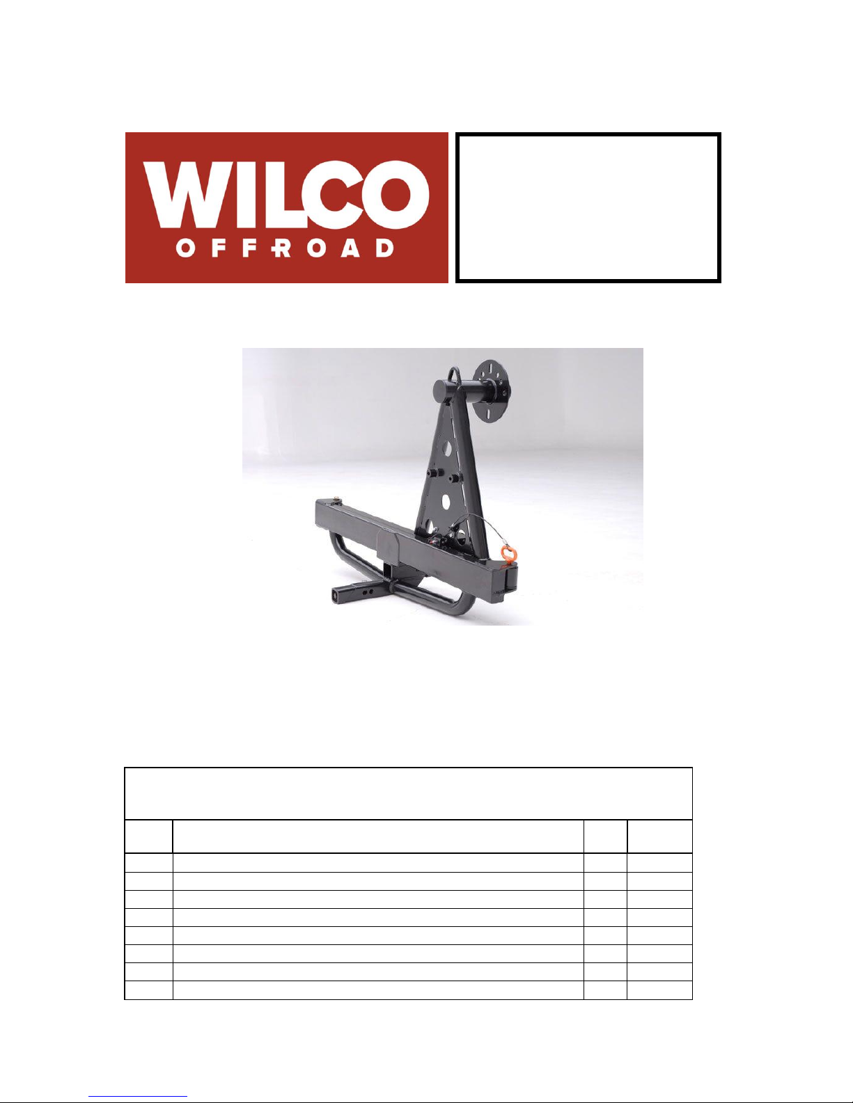
Hitchgate™ Spare
Tire Carrier
Installation Guide
WILCO OFROAD Email: info@wilcooffroad.com
2619 South Oak Street Phone: 1-877-945-2684
Santa Ana, CA 92707
HITCHGATE 4/16/2007 BASIC

9
M12 x 1.5 40MM Full THD GR.8.8
2 10
M12 x 1.5 Wheel Lug nut 3/4" Hex
3 11
Master Lock Cable, 6ft Looped
1
12
Delrin Washer (In-House Fab)
2
13
5/16" Quick Link
1 14
Polyurethane Bushing
1
15
1/2 USS Flat Washer Zinc Yellow
3
16
1/2" Flat Washer SAE Zinc Yellow
2 17
Bracket M14
1
18
Bracket M12
1
19
1/4-20x 7/8 GR8 Hex Bolt
2 20
1/4-20 Nylok Nut
2 21
1/4 GR8 Washer
4
Parts Listed Below are Assembled Before Shipping
ITEM
UHG1060-1, HARDWARE
QTY
PKG
BY
1
TireGate Sticker
2
2
3" Cap - Plug
1 3
1/2 - 13 x 3" Full Thread Hex Bolt
1
4
1/2" Flat Washer
1
5
1/2" Split Washer
1
Rubber Bumper (Pre-installed)
2
WEDGE LOCK
1
rev 070811
Hitchgate™
Installation Instructions
P/N UHG1060 and P/N UHG1070
WARNING
THE HITCHGATE MUST ONLY BE INSTALLED IN A CLASS III or CLASS V
2” HITCH ASSEMBLY.
Tow vehicles maximum trailer rating may be less then the HitchGates rating, see
vehicles owner’s guide for maximum towing and tongue weight.
By installing this product you have used 250 pounds of your current tongue load
capacity. See vehicles owners guide and tow hitch for maximum tongue weight and
reduce by 250lbs (example: Max Tongue wt 600 lbs – 250 lbs = 350 lbs maximum
tongue weight available after installing this product)
HITCHGATE 4/16/2007 BASIC

1. Make sure vehicle is turned off and the emergency brake is set before
installing this product.
2. Remove hitch pin and ball mount.
3. Liberally grease the bolt and anti-rocking wedge-lock on the end of the receiver
insert. See Figure 1.
4. Insert The HitchGate wedge-lock assembly into the vehicles receiver pushing it
to its maximum depth.
5. Align the HitchGate’s hitch pin holes with the receiver’s using the hitch pin. See
Figure 1. Remove the hitch pin.
6. Tighten the anti-rocking wedge lock using a 3/4” socket and a 12” long extension
inserted through the lower 2” tube. Tighten to approx. 75 ft/lbs. (See Figure 2.)
WARNING
THE ANTI-ROCKING WEDGE LOCK IS ONLY TO CONTROL ANY ROCKING
MOTION THE HITCHGATE WOULD HAVE WHILE THE VEHICLE IS IN MOTION.
THIS IS NOT A SAFETY DEVICE. A HITCH PIN MUST BE INSTALLED SECURING
THE HITCHGATE TO THE VEHICLE’S RECEIVER AT ALL TIMES.
7. Reinsert the vehicle’s receiver hitch pin.
8. Insert the tire mount swing arm into the HitchGate frame and insert the latch pin
through the frame’s tabs and the poly-urethane bushing. (See Figure 3.)
9. Place a black plastic thrust washer on the top and the bottom of the round metal
bushing. Grease and then insert the 1/2-13x5 ½” bolt with ½ “ flat washers on the
top and bottom through the bushing and tighten snug. (See figure 3.)
10. Pull the latch pin and test the swing of the HitchGate. If it swings too easily,
tighten the pivot bolt as necessary. If it takes too much effort to make it swing,
loosen the pivot bolt as necessary. (Approx. 35 ft/lbs)
11. Attach the latch pin lanyard to the HitchGate using the supplied hardware. See
Figure 3.
Installing the upper lug bracket
12. There are 2 different upper lug brackets included in your kit. (14mm and 12 mm)
Use the larger one when possible by checking to see if it will work with your rim
or use the same size as you vehicle.
13. Install the bracket using the 2 – 1/4x20 bolts just snug for now. This will allow you
to align the remaining wheel bolts when you mount the tire for the first time.
HITCHGATE 4/16/2007 BASIC
 Loading...