

Page 1
hand-held optical fiber identifier
Operating Instructions
Introduction
The Wilcom OFI Model F6222C Probe is a rugged, hand-held, easy-to-use maintenance and installation instrument that identifies optical fibers by detecting the optical signals that are transmitted through a singlemode fiber. The F6222C utilizes
non-destructive macro-bend detection, which eliminates the need to identify a fiber
by opening it at the splice point. Thus, the probability of interrupting service is
eliminated.
Signals that the F6222C detect include continuous wave live optical transmission,
and low frequency modulated tones at 270, 1000, and 2000 Hz. When the F6222C
detects traffic on a fiber being tested, one of two LEDs on the F6222C illuminates to
indicate the presence and direction of transmission. The presence of tone is indicated by illumination of one of three LEDs (Figure 1). The relative level of core
power within the fiber is also displayed on the two-digit seven-segment LED dis-
Figure 1
tion
play. The F6222C also has an easy to use thumb lock feature for hands-free opera-
F6222C
Operating the F6222C
Operation of the F6222C is simple, as outlined in the
following steps:
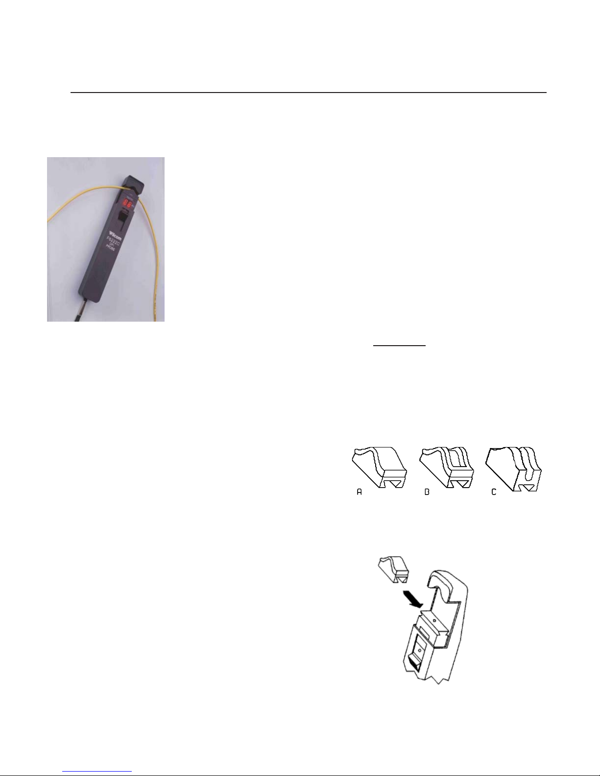
1. Choose an adapter head for the type of fiber to be tested.
The F6222C is supplied with three adapters (as shown in
Figure 2): (A) foam-covered, to accommodate 900 µm buffered fiber; (B) smooth-surfaced with foam perimeter, for
use with ribbon fiber or a 250 µm coated fiber; and (C) slot-
ted, for 3 mm and optional 2 mm jacketed fiber (i.e., pigtails
and jumpers) or loose tube fiber.
2. Select the appropriate adapter and slide it into the mating
slotted channel of the F6222C with slight downward pressure, as shown in Figure 3.
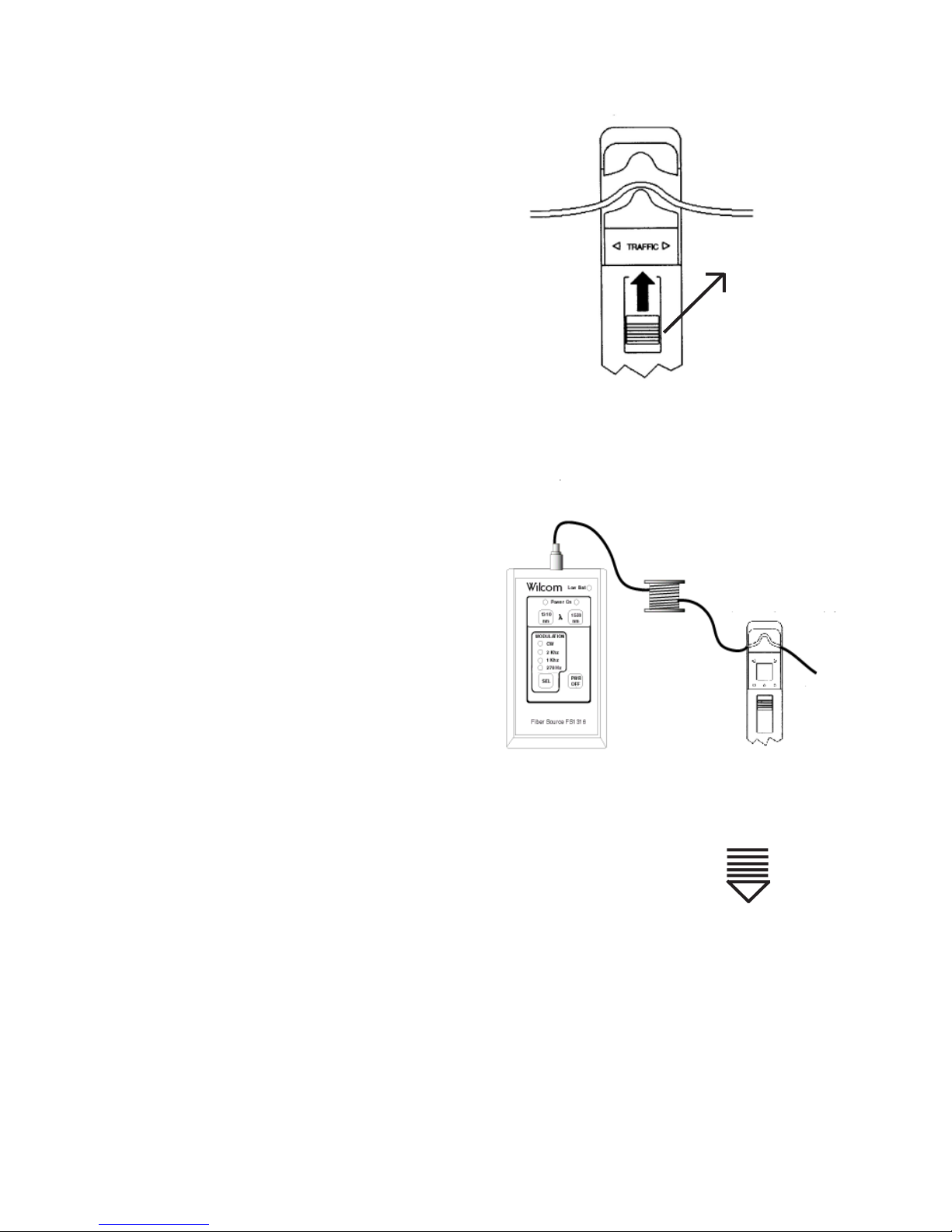
3. Insert the fiber to be tested between the adapter and the top
of the clamp (refer to Figure 4). Slide the thumb switch
upward and ensure that the fiber is installed properly in the
alignment groove.
Figure 2
4. For hands-free operation, slide the thumb switch upward and
“rock” forward to lock, and the fiber will be held in place
( refer to Figure 4 ) “rock” backward to unlock.
04/04
813-219-000
Figure 3
Page 2
Presence of Traffic. Illumination of either Traffic LED
indicates the detection and direction of traffic. This is useful in determining whether the fiber is transmitting or receiving at equipment terminal locations. The F6222C also
provides an audible tone alert when traffic is detected.
Test Tone Detection. Illumination of any one of the 2
kHz, 1 kHz, or 270 Hz LEDs indicates that a test tone is
being detected, which ensures accurate identi-fication of
the fiber that is under test.
The 2 kHz tone can be generated by a source such as
Wilcom Models FS1316 (includes also 1kHz and 270 Hz),
FS1317 (includes also 1kHz and 270 Hz), and FS8514A
(includes also 1kHz and 270 Hz). The F6222C can be used
with all three units, as shown in Figure 5. The recommended wavelength is 1550nm for tone identification.
Relative Power Level . The relative core power in the fiber is displayed as a dB value between +14 and -19 dBm.
The F6222C will operate with core powers greater than
+15 dBm. Under these conditions the F6222C displays a
“HI” and the Traffic LED indications remain valid. When
the core powers are below -19 dB, the F6222C displays
a “LO” and the Traffic LED indications are no longer valid.
The signal level is below the range of the F6222C.
slide the thumb switch upward
and “rock” forward to lock,
and “rock” backward to unlock
Figure 4
Fiber under test
Self Test. Each time the thumb switch is operated, the
F6222C performs a self test. When this occurs all LEDs
will illuminate and then after approximately one-half second turn off.
Figure 5
Low Battery Indication. When the battery voltage be-
comes low, “Lb” is diplayed after the selftest. The unit will continue to operate for some time, but the battery
should be replaced with a fresh 9-volt alkaline battery as soon as possible.
Battery Replacement. To replace battery hold probe in hand, and with thumb on grip, slide cover
downward. Replace battery. To re-install cover reverse the steps. Gently place cover on
probe and align cover keys with probe keyways. Slide cover forward.
Maintenance. It is important that the optical ports remain clean and free of dust, dirt, grease, or other foreign
matter. Cleaning with lint-free swabs and isopropyl alcohol is recommended for optimum performance.
 Loading...