

AWE 120-58
Advanced Wireless
Ethernet Bridge
User Guide
APR 2002 Rev 3


Important
You can obtain the latest customer documentation for this product by visiting our
web site at
information will be posted regularly on this site and can be downloaded via the
www.wi-lan.com
. Click on
Support ➔
Internet.
Customer Documentation
. Updated

Contents
Contents ...............................................................................................i
Important Information ....................................................................vii
Safety Considerations ......................................................................................................................vii
Warning Symbols Used in this Book ...........................................................................................vii
Notices ................................................................................................ix
Copyright Notice ..............................................................................................................................ix
Regulatory Notice .............................................................................................................................ix
Other Notices .....................................................................................................................................x
Warranty & Repair .............................................................................................................................x
Customer Support Contacts ...........................................................................................................x
Distributor Technical Support .......................................................................................................xi
Wi-LAN Product Information ........................................................................................................xi
Publication History ............................................................................................................................xi
Description ..........................................................................................1
Features ................................................................................................................................................1
About Spread Spectrum ....................................................................................................................1
About AWE Units 2
Some System Applications ................................................................................................................3
Making a Simple Wireless Bridge 3
Creating a Simple Wireless Network 3
Creating a Network with Cells 5
Using a Repeater Base 6
Building a WAN 6
Hardware Description ......................................................................................................................7
AWE 120–58 Specifications .............................................................................................................9
APR 2002 Rev 03
i

Installation ......................................................................................... 11
Overview ............................................................................................................................................11
Checking the Shipping Contents 12
Tools and Equipment 12
1 Obtain Network Plan ..................................................................................................................13
2 Assemble Units ..............................................................................................................................13
3 Configure Units .............................................................................................................................15
Configuring a Base Station 15
Configuring a Remote Unit 18
4 Bench Test Units ...........................................................................................................................20
Establishing a Basic RF Link 20
Testing the Link and Adjusting Tx Power 22
Performing Simple Network Tests 24
5 Install Units .....................................................................................................................................26
Point-to-Multipoint Installation 27
Co-Location Installation 27
6 Test Network ................................................................................................................................27
Adding to a Network ......................................................................................................................27
Preventative Maintenance
and Monitoring ..................................................................................................................................28
Configuration .................................................................................... 29
Overview ............................................................................................................................................29
Main Menu 29
Accessing the Main Menu ...............................................................................................................30
Accessing the Main Menu with HyperTerminal® 30
Accessing Units via telnet 31
Setting VT100 Arrows 32
Configuring with the Main Menu ..................................................................................................33
Accessing Help 33
Unit Identification .............................................................................................................................35
Viewing Unit Identification 35
Assigning Unit Identification Information 36
Hardware/Software Revision .........................................................................................................37
Viewing System Revision Information 37
System Software ROM Images ......................................................................................................38
Viewing System Software ROM Images 38
System Current Status ....................................................................................................................39
Viewing System Current Status 39
Network Configuration ..................................................................................................................40
Viewing Internet IP Addresses and Subnet Mask 40
ii
AWE 120-58 User Guide

Setting the Internet IP Address 42
Setting the IP Subnet Mask 42
Setting the Default Gateway IP Address 43
Setting the SNMP NMS Trap IP Address (future) 43
Setting the MAC Filter Entry Age Time Minutes 43
Enabling MAC Address Filtering 44
IP Filter Configuration .................................................................................................................... 45
Viewing IP Filter Configuration 46
Enabling IP Packet Filtering 48
Enabling IP Address Filtering 48
Setting Default IP Address Filtering 48
Setting Up IP Address Filter 49
VLAN Configuration ....................................................................................................................... 50
Viewing VLAN Configuration 50
Port Configuration 50
Press Esc to exit the menu 52
Setting the Default VLAN ID 52
Setting the Port Link Type 52
Setting the Port Priority 53
Setting the Port Acceptable Frame Type 53
Enabling Port Ingress Filtering 54
Enabling Port Egress Filtering 54
VLAN Registration Configuration 55
Creating/Modifying a VLAN Registration Entry 56
Deleting a VLAN Registration Entry 57
Displaying the VLAN Registration Table 58
Below is a sample table:
MAC Address Filter Configuration 58
Creating/Modifying a MAC Address Filter Entry 59
Removing a MAC Address Filter Entry 60
Displaying the MAC Address Filter Table 61
Below is a sample table:
Traffic Class Configuration 61
Á To view the Traffic Class Configuration menu 62
Assigning Packet Priority to Traffic Classes 62
Spanning Tree Configuration 62
Á To view the Spanning Tree Configuration menu 63
Enabling Spanning Tree 64
Setting the Bridge Priority 65
Setting Port Priority 65
Setting Port Path Cost 66
58
61
RF Station Configuration ............................................................................................................... 67
Viewing Current RF Station Configuration 67
Setting the Operating Mode 68
Setting Test Mode Timer Minutes 71
Performing Link Monitor Test (Normal Mode) 72
Performing Transmit and Receive Tests 75
Setting the RF Transmit Status 77
Setting the Link Monitor Period 78
Setting Maximum Remote Distance (Base Station Only) 79
Setting Link Monitor Remote Station Rank 81
Adjusting Throttling (Remote Station Only) 82
APR 2002 Rev 03
iii

Setting Tx Power Automatically (Remote Station Only) 83
Adjusting User Output Power Ceiling (Remote Station Only) 86
Setting Signal Margin (Remote Station Only) 87
Viewing Current Output Power Level Adjust 88
Radio Module Configuration ..........................................................................................................89
Viewing the Radio Module Configuration 89
Setting Config Test Minutes 92
Setting the Station Type 93
Setting the Station Rank 94
Setting the Center Frequency 95
Setting Security Passwords 98
Setting the Scrambling Code 99
Setting the Acquisition Code 100
Adjusting the Tx Power Level 101
Setting a Base to Repeater Mode (Base Station Only) 102
Setting System Symmetry Type (Base Station Only) 104
Setting Dynamic Polling Level (Base Station Only) 105
Setting Remote Unit RF Group 106
Rebooting and Saving RF Module Configurations 109
RF/Ethernet Statistics ................................................................................................................... 111
Viewing RF/Ethernet Statistics 111
System Security .............................................................................................................................. 114
Viewing System Security 114
Assigning Community Names 116
Setting Menu Passwords 117
Allowing Remote Access and Configuration 119
Setting the Auto Logout Minutes 120
System Commands ........................................................................................................................ 121
Viewing System Command Menu 121
Setting Default System Image 122
Setting the Reboot System Image 123
Rebooting the Current Image 123
Restoring Factory Configurations 124
Resetting Radio and Ethernet Statistics 125
Link Monitor Display .................................................................................................................... 126
Viewing Link Monitor Statistics 126
Logout .............................................................................................................................................. 127
Logging Out 127
Command Line Interface ............................................................................................................. 128
iv
Troubleshooting ............................................................................. 129
Administrative Best Practices ..................................................................................................... 129
Troubleshooting Areas ................................................................................................................ 130
Troubleshooting Chart 131
Appendix A: Planning Your Wireless Link .................................. 135
AWE 120-58 User Guide

v
Planning the Physical Layout .......................................................................................................135
Determine the Number of Remotes 135
Ensure LOS and Determine Coverage Area 135
Measure the Distance Between Units 136
Determine Shelter, Power and Environmental Requirements 136
Determining Antenna
and Cable Requirements .............................................................................................................. 136
Determining Unit Configuration Settings ................................................................................ 137
Calculating a Link Budget ............................................................................................................. 137
Link Budget Example ..................................................................................................................... 141
Antenna Basics ............................................................................................................................... 142
Antenna Parameters 142
Implementation Considerations 143
Wi-LAN Approved Antennas 144
Antenna Installation Factors 145
Installing Antennas 146
Fine-tuning Antennas 147
Co-locating Units 147
Appendix B: Using HyperTerminal ..............................................149
Starting HyperTerminal ................................................................................................................ 149
Determining the Communications Port ................................................................................... 150
Appendix C: Configuring a Simple Data Network ......................151
Checking Network Adaptor Installation ..................................................................................151
Configuring the Network ............................................................................................................152
Enabling Sharing on the Hard Disk Drive ................................................................................ 155
Appendix D: SNMP ........................................................................157
About SNMP MIB .......................................................................................................................... 157
Wi-LAN Object Identifier Nodes .............................................................................................. 158
Using SNMP ....................................................................................................................................158
Using Object Identifier Nodes ...................................................................................................159
Appendix E: Configuration Via the Web .....................................171
Overview ......................................................................................................................................... 171
Accessing the Web Pages 171
Web Interface 171
Appendix F: Upgrading Software .................................................175
APR 2002 Rev 03

Obtaining New Software Images ............................................................................................... 175
Downloading Image Software ..................................................................................................... 175
Activating New Software Images ............................................................................................... 177
Removing Old Software Images ................................................................................................. 177
Appendix G: Network Plan Template ......................................... 179
Base Station Information ............................................................................................................. 179
Remote Unit Information and Link Budget ............................................................................. 181
Index ................................................................................................ 183
vi
AWE 120-58 User Guide

Important Information
Please be aware of the following information about the AWE 120-58.
• Tx power of remote units can be monitored and adjusted automatically.
• Center frequency is typed into a data field (rather than selected from a list). Available center frequencies range from 5.7410 GHz to 5.8338 GHz in 400 kHz steps.
• Indoor antennas are not supplied. To test and configure units you need to purchase a Bench Test
Kit (9000-0034). For bench testing, antennas must be separated by at least 2 meters.
Safety Considerations
This documentation must be reviewed for familiarization with the product, instructions, and safety symbols
before operation.
Verify that a uninteruptable safety earth ground exists from the mainpower source and the product’s ground
circuitry.
Verify that the correct AC power source is available for the AC adapter to produce TBD Vdc output from the
adapter.
Disconnect the product from operating power before cleaning.
Warning Symbols Used in this Book
!
WARNING: Bodily injury or death may result from failure to heed a WARNING.
Do not proceed beyond a WARNING until the indicated conditions are fully understood and
met.
! CAUTION: Damage to equipment may result from failure to heed a caution.
Do not proceed beyond a CAUTION until the indicated conditions are fully understood and
met.
Important: Indicates important information to be aware of which may affect the completion of
a task or successful operation of equipment.
WARNING
!
APR 2002 Rev 03
vii

Important Information
All antennas and equipment must be installed by a knowledgeable and
Never operate a unit without an antenna, dummy load, or terminator
Operating a unit without an antenna, dummy load, or terminator connected
Antennas must be selected from a list of Wi-LAN approved antennas.
professional installer.
! CAUTION
connected to the antenna port.
to the antenna port can permanently damage a unit.
Important
See Wi-LAN Approved Antennas , page 144 for list.
viii
AWE 120-58 User Guide

Notices
Copyright Notice
Copyright© 2001 Wi-LAN, Inc.
All rights reserved.
This guide and the application and hardware described herein are furnished under license and are subject to a
confidentiality agreement. The software and hardware can be used only in accordance with the terms and
conditions of this agreement.
No part of this guide may be reproduced or transmitted in any form or by any means—electronic,
mechanical, or otherwise, including photocopying and recording—without the express written permission of
Wi-LAN, Inc.
While every effort has been made to ensure that the information contained in this guide is correct, Wi-LAN,
Inc. does not warrant the information is free of errors or omissions.
Information contained in this guide is subject to change without notice.
Regulatory Notice
The AWE 120-58 product presented in this guide complies with the following regulations and/or regulatory
bodies.
• RSS-210 of Industry Canada (www.ic.gov.ca)
• FCC Part 15 (www.fcc.gov)
Operation is subject to the following two conditions.
• This device may not cause interference
• This device must accept any interference, including interference that may cause undesired operation
of the device
This equipment generates, uses, and radiates radio frequency and, if not installed and used in accordance with
this guide, may cause harmful interference to radio communications. However, there is no guarantee that
interference will not occur in a particular installation.
APR 2002 Rev 03
ix

Notices
If this equipment does cause harmful interference to radio or television reception, which can be determined
by turning the equipment off and on, the user is encouraged to try to correct the interference by one or
more of the following methods.
• Reorient or relocate the receiving antenna
• Increase the separation between the equipment and receiver
• Connect equipment to an outlet on a circuit different from that to which the receiver is connected
• Consult the dealer or an experienced radio/TV technician for help
• Selecting and testing different channels, if employing 5.8 GHz equipment
As the AWE 120-58 is used on a license-exempt, non-frequency coordinated, unprotected spectrum
allocation, and thus can be subject to random unidentified interference, applications must not be those of a
primary control where a lack of intercommunication could cause danger to property, process, or person. An
alternative fail-safe should be designed into any system to ensure safe operation or shut down, should
communication be lost for any reason.
Other Notices
• Changes or modifications to the equipment not expressly approved by Wi-LAN, Inc., could void the
user’s authority to operate the equipment.
• Appropriately shielded remote I/O serial cable with the metal connector shell and cable shield
properly connected to chassis ground shall be used to reduce the radio frequency interference.
• Radio frequency exposure limits may be exceeded at distances closer than 23 centimeters from the
antenna of this device.
• All antenna installation work shall be carried out by a knowledgeable and professional installer.
• Use only a power adapter approved by Wi-LAN.
Warranty & Repair
Please contact the party from whom you purchased the product for warranty and repair information.
Wi-LAN provides no direct warranty to end users of this product.
Customer Support Contacts
Users of Wi-LAN equipment who require technical assistance must contact their reseller or distributor. For
information on distributors in your area, please visit www.wi-lan.com/channel.
x
AWE 120-58 User Guide

Distributor Technical Support
Distributor Technical Support
Distributors may contact Wi-LAN’s Technical Assistance Center (TAC) for technical support on Wi-LAN
products. When requesting support, please have the following information available:
• Description of the problem
• Configuration of the system, including equipment models, versions and serial numbers.
• Antenna type and transmission cable lengths
• Site information, including possible RF path problems (trees, buildings, other RF equipment in the
area)
• Configuration of units (base, remote, channels used, etc.) and Link Monitor statistics
Contact Wi-LAN’s Technical Assistance Center at the numbers listed below.
Canada and USA Call toll free: 1-800-258-6876
Business hours: 7:30 a.m. to 4:30 p.m. Mountain Standard Time (GMT-7:00)
International Call: 1-403-204-2767
Business hours: 7:30 a.m. to 4:30 p.m. Mountain Standard Time (GMT-7:00)
All locations Send an e-mail message to:
techsupport@wi-lan.com
Wi-LAN Product Information
To obtain information regarding Wi-LAN products, contact the Wi-LAN distributor in your region, call
1-800-258-6876 to speak with a Wi-LAN sales representative or visit our web site at www.wi-lan.com.
Publication History
Revision Date Description
Rev 1 APR 2002 Initial release of manual.
APR 2002 Rev 03
xi

Notices
xii
AWE 120-58 User Guide

Description
Features
The AWE 120-58 advanced wireless Ethernet bridge provides high-speed, wireless connectivity at a fraction
of the cost of wired solutions. It operates over the 5.7250 – 5.8500 GHz ISM radio band and has a maximum
raw wireless data rate of 12 Mbps.
• Provides wireless connectivity at speeds up to eight times faster than regular T1 lines, making the
AWE 120-58 ideal for providing high-speed Ethernet access or for wirelessly extending existing
communications infrastructures.
• Supports point-to-point, point-to-multipoint, and multipoint-to-multipoint networks (if all remotes have
clear line of sight to the base station and to each other). Contentionless polling ensures efficient access to
remote data networks.
• Is self-contained and easy to use. Simply connect an AWE unit to each LAN segment, and the unit
automatically learns where nodes are located on the network and performs dynamic packet filtering to
ensure the local LAN traffic does not overload the wireless connection.
• Uses Wi-LAN's patented Multi-Code Direct Sequence Spread Spectrum (MC-DSSS) technology, which
makes the unit spectrally efficient and resistant to interference. MC-DSSS technology increases data
throughput by as much as ten times compared to traditional spread spectrum technology.
• Other features include automatic Tx power level adjustment, IP address filtering, throughput throttling and
monitoring, high security and reliability, and a flash-code upgrade path. SNMP, telnet and RS-232
management enable users to manage, configure and monitor their wireless network with ease.
• VLAN compliant—supports transparent forwarding of VLAN-tagged frames (increased frame size
supported) and remote management of units within a VLAN environment (i.e. units connected via trunk
links). Supports VLAN tag insertion/removal and VLAN supporting protocols (802.1D, 802.1P, GVRP).
About Spread Spectrum
Three frequency bands (called the ISM bands) are allocated in Canada and the United States to a radio
technique known as spread spectrum communication. The bands are located at 900MHz, 2.4 GHz, and 5.8
GHz (shown in the following illustration). The AWE 120-58 operates with spread spectrum technology over
the 5.7250 – 5.850 GHz band.
APR 2002 Rev 03
1

Description
License-Free ISM Bands
900 MHz
2.4 GHz
5.8 GHz
26 MHz Wide
902 MHz 928 MHz
83.5 MHz Wide
2.4 GHz 2.4835 GHz
125 MHz Wide
5.725 GHz 5.85 GHz
Direct Sequence Spread Spectrum (DSSS) technology converts a data stream into packets and spreads the
packets across a broad portion of the RF band. The particular spread pattern depends upon a code. With
multi-code DSSS (MC-DSSS), multiple codes and spread patterns are employed. A spread spectrum receiver
reconstructs the signal and interprets the data.
Some advantages of DSSS are as follows:
• Resistant to interference: DSSS overcomes medium levels of interference and multipath problems.
• Security: There must be a decoder at the receiving end to recover data (an AWE can only talk to
another AWE). Data is transmitted at irregular time intervals.
• Low probability of detection: Due to a low amplitude signal and wide bandwidth.
• No license fee: A license fee is not required if used in the specified radio bands and the transmitter
power is limited.
About AWE Units
AWE 120-58 units can function as base stations, remote units or repeater bases.
Base Station: One unit in your wireless network must be a base station. A base station acts as the central
control unit of the wireless network. The base station polls all remote units and controls how traffic is routed
to and from remotes. The base usually connects to a major access point of the wired network. The antenna of
the base station must be capable of transmitting and receiving radio signals to and from all the remote units in
a system. If remotes are spread over a large area, an omni-directional antenna is usually required. See
Configuring a Base Station
, page 15 for information about setting up a base station.
2
AWE 120-58 User Guide
Some System Applications
Remote Units: Remote units receive and transmit wireless data to the base station. You need at least one
remote unit for each wireless link. Remotes can limit the amount of data passed by the remote (a function
called throttling), and they can filter data packets based on their IP address. If remote units communicate only
with the base station, their antennas can be more directional and have higher gains than base antennas. See
Configuring a Remote Unit
, page 18 for information about setting up a remote unit.
Repeater Base: A base station can be configured as a repeater base. A repeater is needed when remote
units cannot communicate directly with each other, but direct transfers of data between them are necessary
(as in a true WAN). When configured as a repeater, the base station passes data packets between remote
stations based on the remote group status and a list of MAC (Media Access Control) addresses that the base
station automatically builds. A single repeater uses a method called “store and forward” to receive data from
the originating remote and to pass data to the destination remote. See Setting a Base to Repeater Mode
(Base Station Only)
, page 102 for more information. Two units can also be employed as a dual unit repeater
(back-to-back) configuration that maximizes data throughput.
Some System Applications
You can build a wireless network from AWE units and various other components such as cables and antennas.
The following section shows some simple examples of AWE applications.
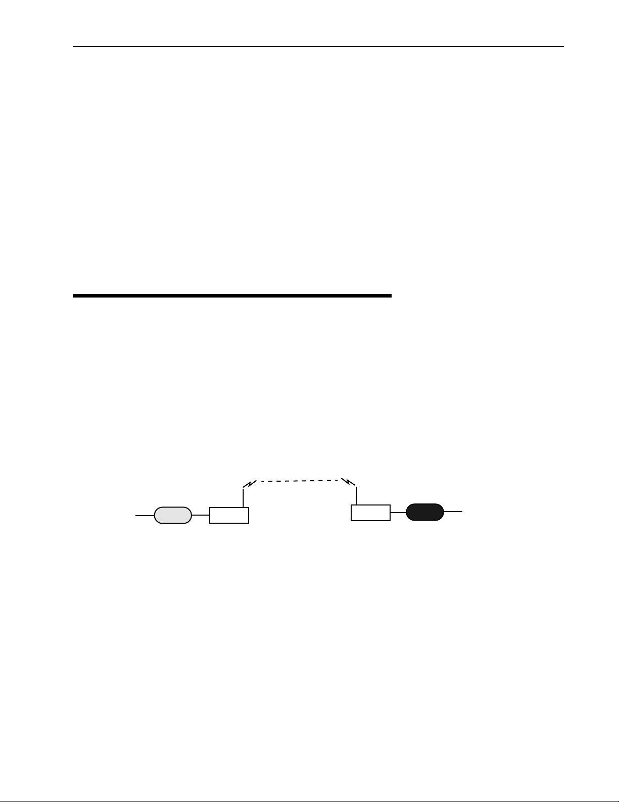
Making a Simple Wireless Bridge
The simplest example of using a AWE 120-58 is a point-to-point wireless bridge that connects two wired
network segments or LANs. Two AWE units are required: a base station and a remote unit.
Point-to-Point Wireless Bridge
Wireless Link
Wired Network
Switch
Hub
Firewall
RemoteRouter
Base
Main Wired Network
Router
Hub
Switch
Firewall
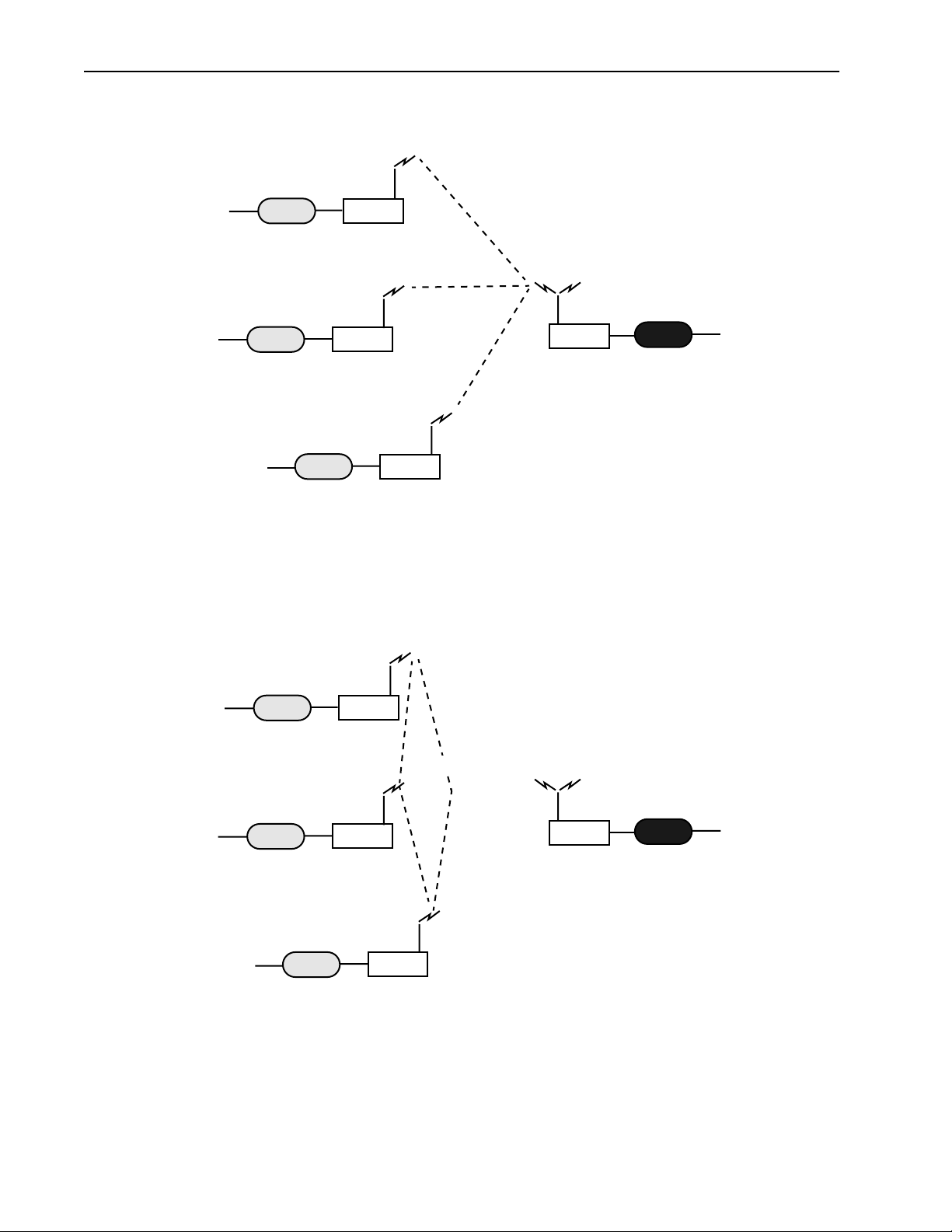
Creating a Simple Wireless Network
You can create a point-to-multipoint wireless network by adding several remote units to a base station. A
base station can support up to 1000 remotes, however, Wi-LAN recommends no more than 225 remotes per
base station to ensure high levels of data throughput. See Determine the Number of Remotes
for more information.
APR 2002 Rev 03
, page 135
3
Description
Point-to-Multipoint Wireless Network
Wired Network
Switch
Hub
Firewall
Wired Network
Switch
Hub
Firewall
Wired Network
RemoteRouter
Wireless Links
Main Wired Network
RemoteRouter
Base
Router
Hub
Switch
Firewall
Base station polls
Remote Units
Hub
Switch
Firewall
RemoteRouter
Direct remote-to-remote communication can occur if a direct RF link can be established between remotes,
and if remotes are in the same RF group.
Remote-to-Remote Communication
Remote
Wireless Links
Main Wired Network
Remote
Base
Remotes must be in the same
RF group to communicate
directly
Remote
4
AWE 120-58 User Guide
Some System Applications
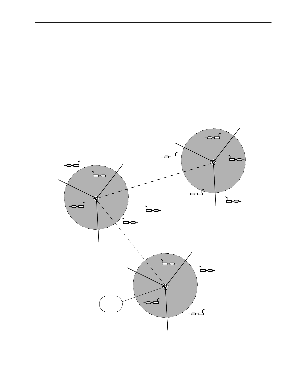
Creating a Network with Cells
Cells or data nodes can be created with AWE units to maximize coverage, minimize interference, and
increase data throughput. Directional antennas are mounted on a mast to divide cells into sectors.Each sector
is connected to an antenna and a base station. Directional antennas increase signal gain within the sector and
increase the distance possible between base stations and remotes. Center frequency, acquisition code and
antenna polarization techniques are used to isolate sectors. The increase in data rate depends on the number
of sectors. For example, the data rate of Cell 1 in the diagram below is 36 Mbps (12 Mbps x 3 sectors). Cells
are distributed across a service area and can be linked to each other via a wireless link or a fiber optic cable.
Implementing a network with cells requires comprehensive network planning and site preparation. Please
contact Wi-LAN for information about creating a network with cells.
LAN with Cells and Sectors
Cell 2
Remote
Remote
Cell 1
Remote
Base
Stations (3)
Fiber Optic Cable or
Remote
Remote
Fiber Optic Cable or Wireless Link
In this example, cells are divided into120 degree sectors.
Cells are linked to other cells by a wired or wireless link.
Remote
Wireless Link
Cell 3
Remote
Remote
Remote
Remote
Base
Stations (3)
Remote
Remote
APR 2002 Rev 03
Internet
Remote
Base
Stations (3)
Remote
5
Description
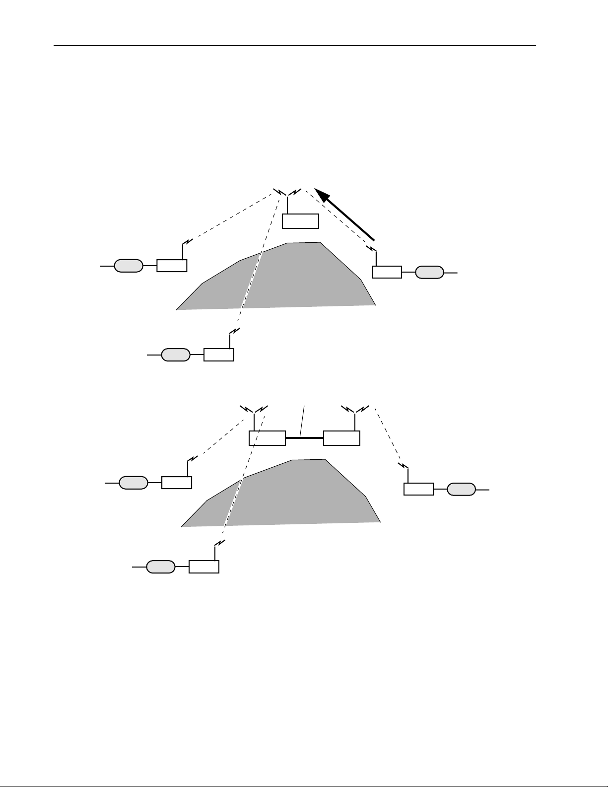
Using a Repeater Base
A base station can function as a repeater to enable wireless data communication around physical obstacles
such as tall buildings or mountains. The repeater passes data around the obstacle to any remote in the same
RF group. The single unit repeater slows data throughput due to the “store and forward” process where each
packet is handled twice. A dual unit repeater does not slow data throughput.
Base Station as a Repeater
Single Unit Repeater
Wired Network
3
Remote
Wired Network
Dual Unit Repeater
Wired Network
3
Remote
Wireless Links
2
Remote
Wireless Links
Repeater
Mountain
Ethernet
Base Base
Mountain
Wired Network
1
Remote
Wired Network
1
Remote
Wired Network
2
Remote
Building a WAN
LAN segments can be linked with AWE units to build a WAN (Wide Area Network). Wi-LAN networks are
installed in many locations around the world. You can contact Wi-LAN for help designing your network.
6
AWE 120-58 User Guide
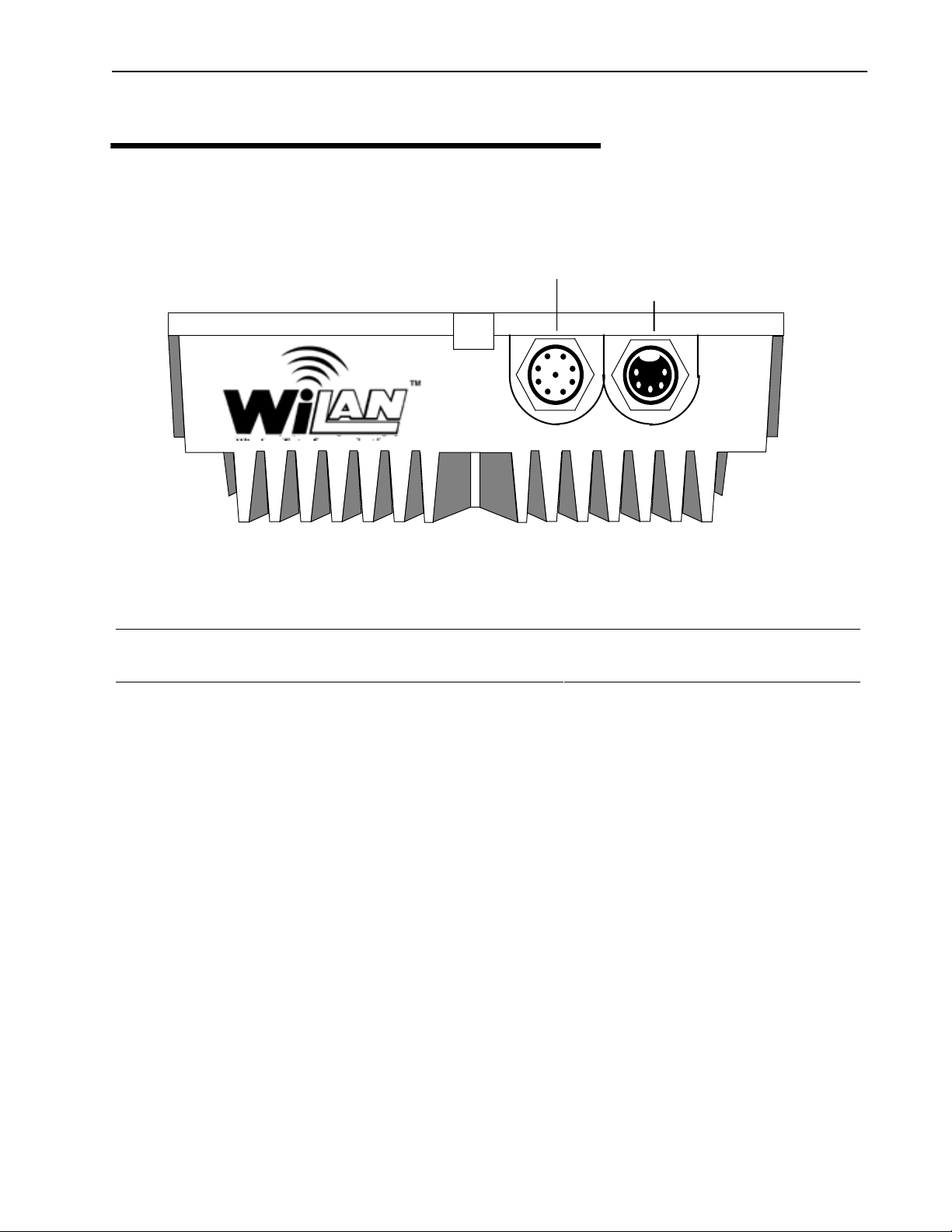
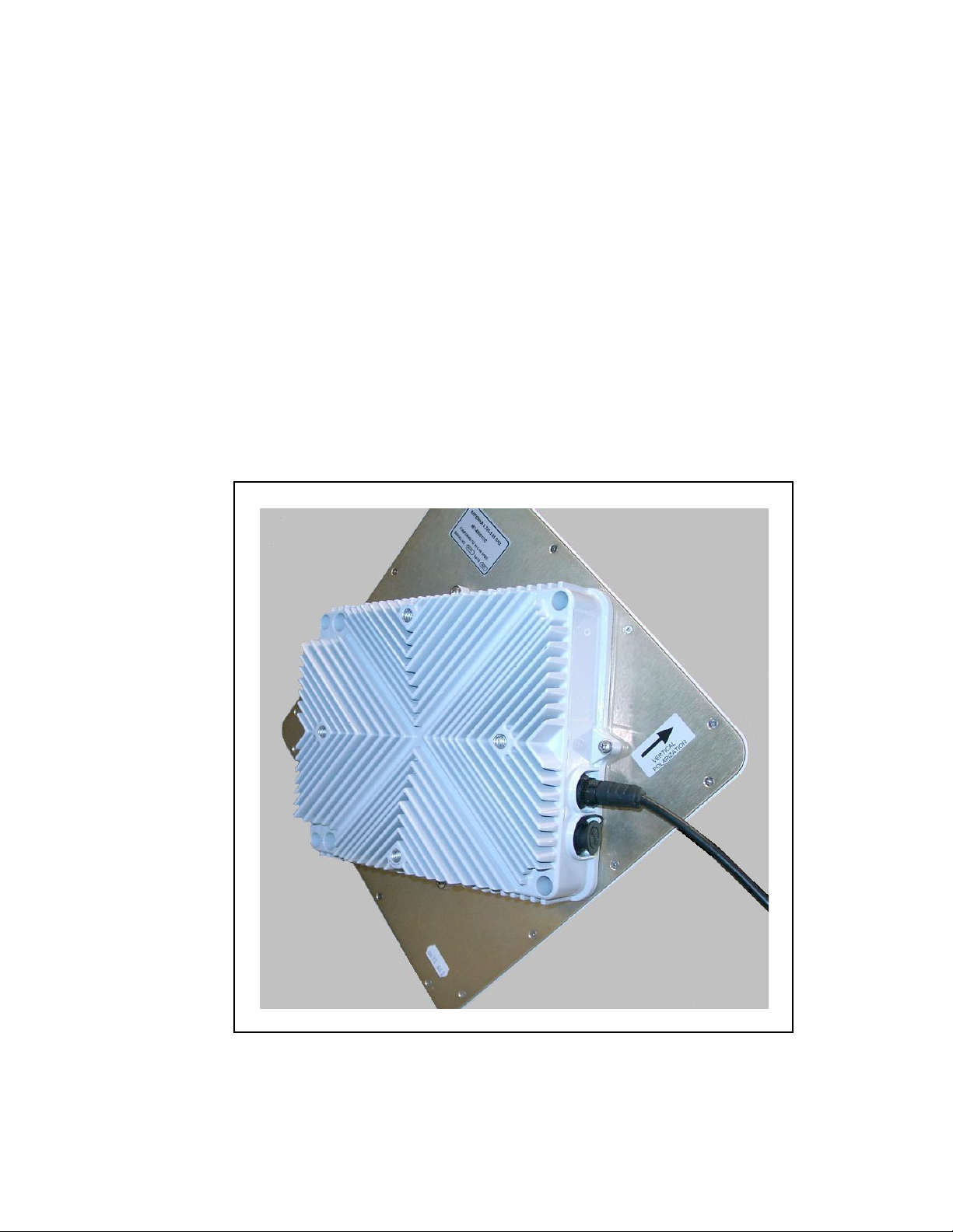
Hardware Description
Hardware Description
The AWE 120-58 unit has two connector ports located on the access panel. One port receives Power and
Ethernet via a special connector cable (see below). The second port provides Serial management access.
Access Panel
Power/Ethernet Port
Serial Port
The access panel connectors are further described below
Power/Ethernet Port 8-pin male connector. A matching connector cable is provided with your
shipping package
Serial Port 5-pin female connector. A matching connector cable is available separately
(not provided with your shipping package)
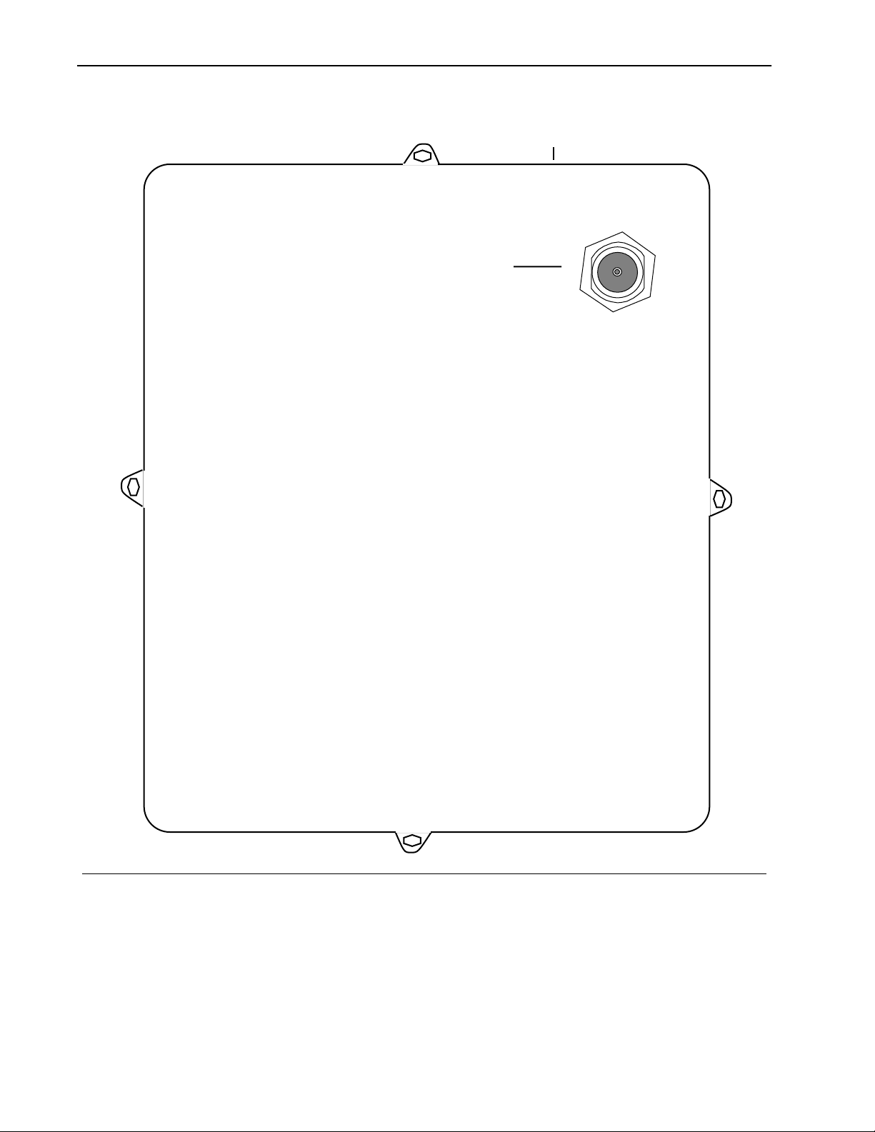
The top panel for a unit with a separate antenna connection is shown below. It contains a cover plate with an
N-type antenna connector. An integrated antenna may alternatively replace this cover plate, providing a direct
RF connection.
APR 2002 Rev 03
7
Description
Top Panel
Cover Plate
Antenna
Port
Antenna N-type female connector antenna port is located at the top right of the top
panel. This port may be connected to an antenna directly or through a 50
ohm coaxial cable
8 AWE 120-58 User Guide

AWE 120–58 Specifications
AWE 120–58 Specifications
General Specifications
Modulation Method: Multi-Code Direct Sequence Spread Spectrum (MC-DSSS), time
division duplexing (TDD)
Wireless Data Rate: 12 Mbps raw data rate/up to 10.2 Mbps operational
RF Frequency Range: 5.725 - 5.850 MHz (unlicensed ISM band)
Power Requirements: TBD Vdc (via 110/240 VAC 50/60 Hz adaptor)
15W maximum power consumption
Physical (for units with integrated
antenna):
Size (W x L x H): 30.5 x 30.5 x 8.4 centimeters
(12 x 12 x 3.3 inches)
Weight: 3.6kg (7.9 lb.)
Physical (for units with separate
antenna):
Size (W x L x H): 8.6 x 10.3 x 8.1 centimeters
(8.6 x 10.3 x 3.2inches)
Weight: 3 kg (6.6 lb.)
Radio Specifications
Antenna Connector: N-type female (for units with separate antenna)
Max. Transmit Output Power:
Receiver Sensitivity:
+21 dBm +/– 1 dBm (after unit temperature is settled)
Better than – 80 dBm (1 x 10
–6
BER) mid-channel1l
Processing Gain: >10 dB
System Gain Better than 101 +/– 1 dB
Center Frequency 5.7410 GHz–5.8338 GHz in 400 kHz steps
Bandwidth 33 MHz null to null
1
Transmit Power and Sensitivity specifications are for mid-channel
and room temperature. Across frequency and temperature range,
these specifications are within +/– 2 dBm
1
Network Support
Packet Format: IEEE 802.3 and Ethernet II
(High-level protocol transparent)
LAN Connection: 10/100BaseT (auto negotiates)
Bridge Functionality: Local Packet Filtering (self-learning)
Static IP address filtering
Dynamic polling of remotes
User configurable data rate (throttling)
Software is upgradeable online via ftp
APR 2002 Rev 03
9

Description
Wireless Networking
Protocols
Network Topologies: Point-to-Point, Point-to-Multipoint, Multipoint-to-Multipoint
Repeater Mode: User Configurable
Private Network User configurable using repeater and RF Group
RF Collision Management: Dynamic Polling with Dynamic Time Allocation
Security
Data Scrambling: User Configurable
Data Security Password: Security password of up to 20 bytes in length
48
combinations)
(10
Configuration, Management, and Diagnostics
Configuration Methods: Web, SNMP, telnet and RS-232 Serial Port
SNMP: Version I compliant (RFC 1157), MIB standard and enterprise
(RFC 1213)
Management Port Functionality: Supports system configuration, security, access control,
wireless LAN diagnostics and management, menu-driven
ASCII interface via RS-232 DB-9 connector
Environment
Units are fully weather proof.The operating ambient
temperature range is from -40º to 60º Celsius.
10 AWE 120-58 User Guide
Installation
Overview
This section explains how to install AWE units. You will first assemble, configure and test units in a controlled
environment so that any problems can be solved easily, and then install units in the field. By going through this
process, you will ensure a successful installation, save time spent on-site, and reduce travel from site to site.
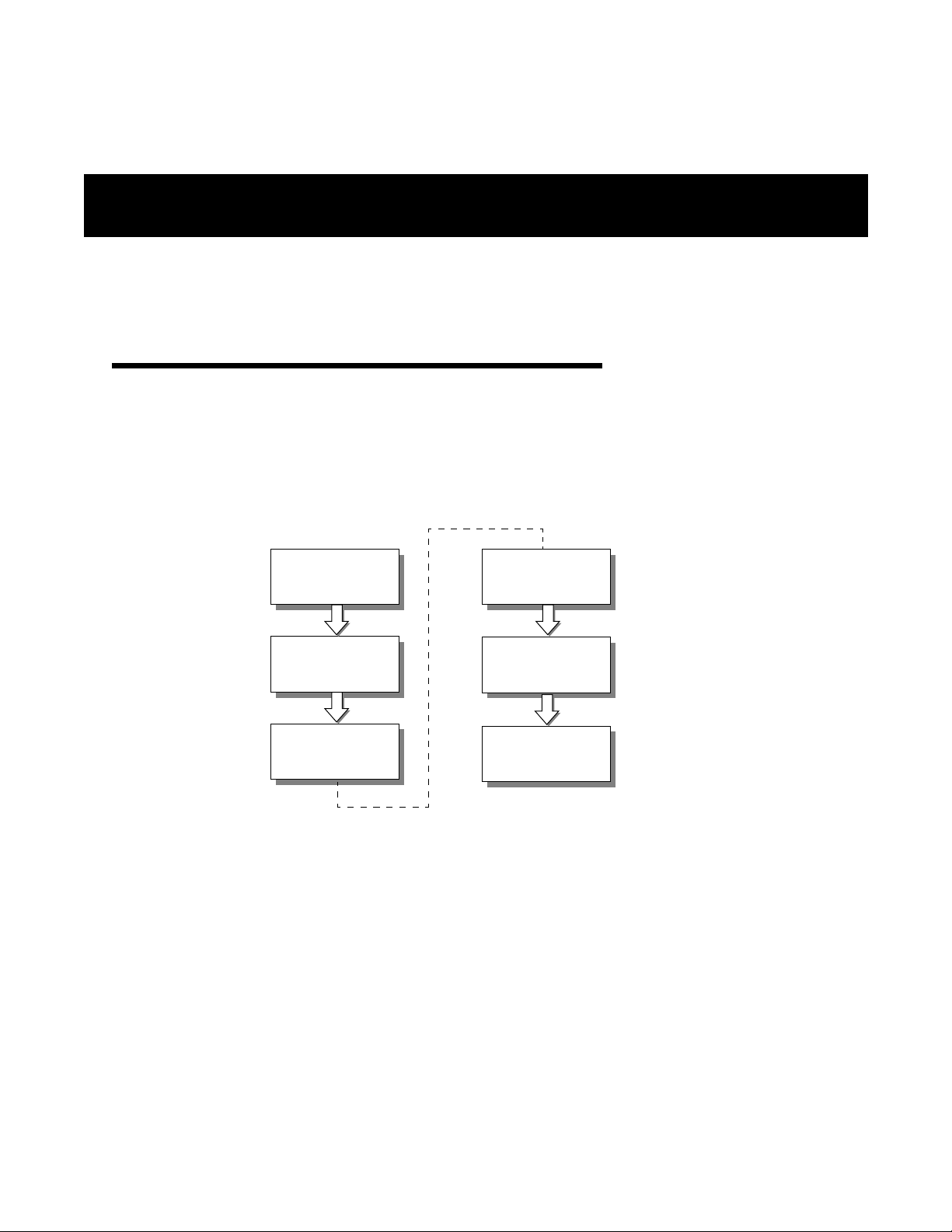
The following basic process should be followed.
1
2
3
Obtain
Network Plan
Assemble
Units
Configure
Units
4
5
6
Bench Test
Units
Install
Units
Test
Network
1. Obtain your network plan (see Appendix G: Network Plan Template on page 179 ), equipment and
tools.
2. Assemble units.
—Check the contents of each AWE shipping package to ensure that you have received the required parts.
—Connect an indoor antenna or dummy load, connect the power supply unit and check the power.
3. Configure units—Set unit parameters according to the network plan.
4. Bench test units—Test basic RF and network operation of units in a controlled environment.
5. Install units—Place the tested units in their field locations and connect them to antennas, the wired
network, and power. Install the ferrite block around the 10/100BaseT Ethernet cable.
6. Test Network—Test the operation of the installed network.
APR 2002 Rev 03 11

Installation
Checking the Shipping Contents
Check the contents of each AWE shipping package to ensure that you have received all the materials. Note
that there are two possible packages available for units shipped with or without an integrated antenna. Verify
the package type you ordered and refer to the appropriate list(s) below.
Common items for both shipping packages include:
• AWE unit
• Power supply (includes one (1) Power Inserter Unit and one (1) Power/Ethernet cable)
• Unit mounting accessories (includes four (4) lock washers, four (4) lock nuts, four (4) flat washers,
four (4) threaded rods, and two (2) clamping plates)
• Two (2) end caps
• Installation and Configuration Guide (CDROM or hardcopy)
• Warranty Card
If you ordered the integrated antenna shipping package, the following additional item(s) should be included:
• TilTek 23 dBi integrated antenna
Otherwise, the following additional item(s) should be included:
• Cover plate
If any of the above items are not included in the AWE 120-58 shipping package, contact Wi-LAN customer
support.
You may also require the following items.
• Cable, straight-through Ethernet RJ45, when connecting a unit to a hub
• Cable, crossover Ethernet cable RJ45, when connecting directly to the Ethernet port of a PC
• AWE 120-58 Serial cable (DB9 female connector to AWE 120-58 5-pin male connector)
• DB9 to DB25 serial adaptor
You can purchase these items and other parts from Wi-LAN or any authorized supplier.
Tools and Equipment
Ensure that you have all the required parts and equipment specified in the network plan. You will require a
laptop PC with HyperTerminal® or other terminal emulation software and RS-232 cable to install and
configure units. You may require a spectrum analyzer, Site Master® communication test set, digital multimeter,
2-way radios, binoculars, strobe lights, ladder, and weatherproof caulking.
If your unit contains a separate antenna connection, additional equipment is required to perform RF link
bench tests. The following examples and illustrations assume a separate antenna is used. If your unit contains
an integrated antenna, additional equipment may be required for antenna mounting.
12 AWE 120-58 User Guide

1 Obtain Network Plan
1 Obtain Network Plan
The network plan describes the network in detail, including the following.
• Type and number of units
• Physical layout
• Configuration settings for each unit
• Site names, IP addresses and links
• Antenna types, RF cables and cable lengths, surge suppressors, terminators
• Network cable types and lengths
• Grounding kits and backup power requirements
• Link budget
• Floor plans and equipment cabinet requirements
A plan should be completed before any equipment is installed in the field. See Appendix A: Planning Your
Wireless Link , page 135 and Appendix G: Network Plan Template on page 179 for more information about
network plans.
2 Assemble Units
To assemble a unit and check the power
➧
1. Connect the indoor antenna to the Antenna port on the top panel of the unit.
Note: Indoor antenna may be different from the illustration.
! CAUTION
Never operate a unit without an antenna, dummy load, or terminator
connected to the antenna port.
Operating a unit without an antenna, dummy load, or terminator connected
to the antenna port can permanently damage a unit.
! CAUTION
The AWE 120-58 must be connected only to a Wi-LAN Power Inserter Unit
to provide appropriate power (and Ethernet)
APR 2002 Rev 03
13
Installation
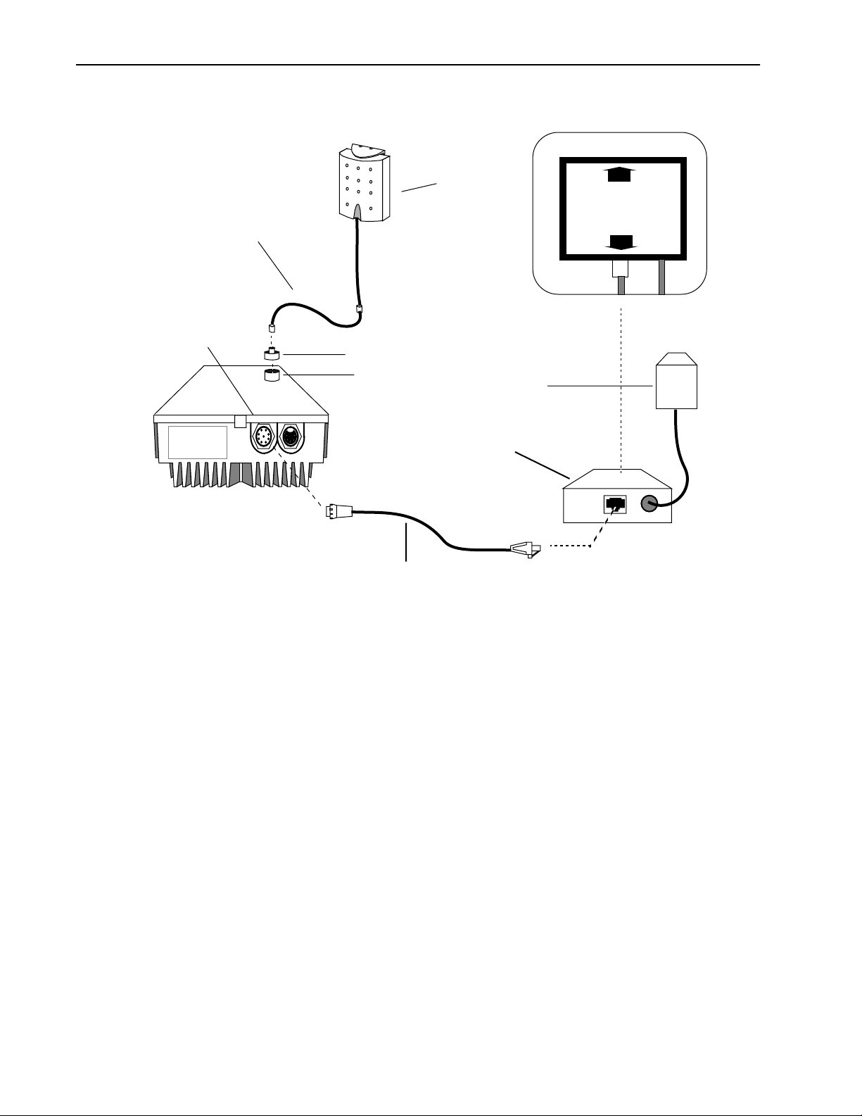
Antenna and Power Connections
Indoor
Antenna
Top View Detail
To LAN
Power / Ethernet port
2. Check the power
Coaxial Cable
SMA to N-type Adaptor
Antenna port
Power / Ethernet Cable
To radio
Power Adaptor
Power Inserter
a) Plug the 8-pin female connector on the Power/Ethernet cable into the unit’s Power/Ethernet port
b) Plug the RJ45 connector on the Power/Ethernet cable into the Power Inserter Unit’s RJ45 port
labelled “To radio” (see above diagram)
c) Plug the TBD VDC Power Adaptor on the Power Inserter Unit into the AC power outlet.
The Power LED on the Power Inserter Unit displays GREEN if power is correctly supplied to the
unit. Otherwise, the LED displays ORANGE.
If the Power LED does not display GREEN, check your AC power source and the power supply unit.
Verify the Power/Ethernet cable is connected to the correct RJ45 port on the Power Inserter Unit
and that a secure connection is made with the 120-58 Power/Ethernet port.
14 AWE 120-58 User Guide
3 Configure Units
3 Configure Units
This section describes how to configure a base station and a remote unit, which are the basic units required
for a point-to-point wireless link. Once you have configured and tested this basic equipment, you can
configure and test all remaining units. See Configuration , page 29 for detailed information about
configuration settings.
Configuring a Base Station
When you configure a unit as a base station, you need to perform the following tasks.
• Check the Network Configuration information of the unit
• Set the Station Type of the unit to “Base Station”
• Assign the Station Rank (# equal to or greater than the number of remote units)
• Choose a Center Frequency (must be the same for all units in network)
• Select an Acquisition Code (must be the same for all units in network)
• Set Tx Power Level Adjust initially to “0 dB”
• Set the security passwords (must be the same for all units in network)
• Change the default menu passwords
These tasks are described below in detail.
To configure a unit as a base station
➧
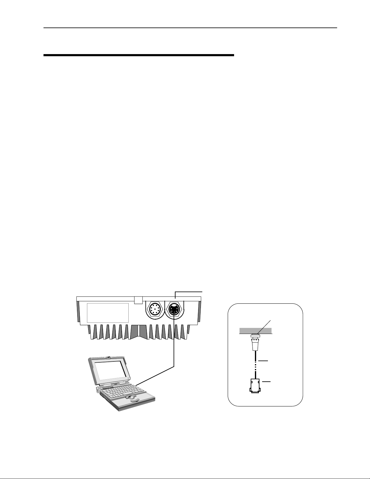
1. Connect a PC to the AWE unit that will be the base station. Connect the COM port of the PC to the
serial port of the AWE via an AWE 120-58 Serial cable.
Connecting PC to Serial Port
AWE Unit
RS-232 Serial Cable
to PC COM port
Serial Port
(See detail)
Detail
AWE
Serial Port
AWE 120-58
Serial cable
DB9
(female)
APR 2002 Rev 03
PC
15

Installation
2. Start HyperTerminal® (see Appendix B: Using HyperTerminal , page 149 for details) or another
terminal emulation program such as Tera Term™. Use the following communication settings: 9600 bps, 8
bits, no parity, 1 stop bit, no flow control.
3. Press
Enter. The AWE 120-58 Login window is displayed.
Wi-LAN AWE 120-58 Login
S/N: Serial-Number
MAC Address: 001030000000
Software: Rev 4.0.0 (Apr 20 2002 10:13:37)
Hardware: Rev 4.0.0 (4MB SDRAM, 2MB Intel Flash)
Enter Password:
4. Type the default password (supervisor) and press
Enter. The Main Menu is displayed.
Note: supervisor enables you to change the configuration settings with the Main Menu. See Setting
Menu Passwords , page 117 for more information about menu passwords.
Main Menu
How to Use the Main Menu
Wi-LAN AWE 120-58 Main Menu
• To select an item from the Main
Menu or a sub-menu, press the
-> Unit Identification
Hardware/Software Revision
System Software ROM Images
Current System Status
Network Configuration
IP Filter Configuration
VLAN Configuration
RF Station Configuration
Radio Module Configuration
RF/Ethernet Statistics
System Security
System Commands
Link Monitor Display
Logout
keyboard arrow keys to
move the cursor –> next to the
item.
Press the
Enter key to
Enter
open the data entry field.
• To scroll through items in the data
entry field, press .
Press to select an item
Enter
from the field.
• To exit from a menu, press the
Esc
key.
Esc
5. Select Network Configuration. Check the network configuration information, the IP address and
subnet mask settings. If necessary, change settings to match the network plan.
16 AWE 120-58 User Guide

3 Configure Units
6. From the Main Menu, select Radio Module Configuration and press Enter. The Radio Module
Configuration window is displayed.
H - Help Radio Module Configuration
New Current Flash
Station Type -> Remote Unit Remote Unit Remote Unit
Station Rank (1-1000) 1 1 1
Center Frequency (57410-58338) 5.7874 GHz 5.7874 GHz 5.7874 GHz
Security Password 1 (Hex) 1 1 1
Security Password 2 (Hex) 10 10 10
Security Password 3 (Hex) 100 100 100
Security Password 4 (Hex) 1000 1000 1000
Security Password 5 (Hex) 10000 10000 10000
Scrambling Code (Hex) 0 0 0
Acquisition Code (0-15) 1 1 1
Config Test Minutes (1-120) 30 30 30
Tx Power Level Adjust 0 dB 0 dB 0 dB
Base Station Only Parameters
Repeater Mode off off off
System Symmetry Type Asymmetric Asymmetric Asymmetric
Dynamic Polling Level (1-100) 1 1 1
Remote Station Only Parameters
Remote Unit RF Group (0-63) 0 0 0
Reboot New RF configuration Press Enter to Execute
Save Current Config to Flash Press Enter to Execute
• Select Station Type. Choose Base Station.
• Select Station Rank. Enter the total number of remote units in your wireless network. For
example, if you have only one remote unit, enter “1”. If there are 20 remote units, enter “20”.
• Choose a Center Frequency. Enter the value of the center frequency (range is 57410–58338
in 400 kHz steps). All wireless units must be set to the same center frequency.
• Select Security Password x. Enter security passwords (each password can be up to eight
digits long in hexadecimal) for the unit. All units in the same network must have the same set of
security passwords.
• Select Scrambling Code. Enter a hexadecimal value or leave the default at “0”. All units in the
same network must have the same scambling code.
• Select Acquisition Code. Enter a value from 0–15. (All units in the same network must have
the same acquisition code.)
• Select Config Test Minutes. Enter a time in minutes, for example, 10. The unit will automatically reboot when this time period expires, and uses the settings stored in flash memory instead of
current settings.
• Select Tx Power Level Adjust. Choose an initial value of 0 dB, which means no Tx power
attenuation.
• Select Reboot New RF configuration and press
Enter. The unit reboots and the Login
window is displayed.
7. Log in to the unit. (Type supervisor for the password). The Main Menu is displayed.
8. Select Radio Module Configuration and press
Enter. The Radio Module Configuration window
is displayed.
APR 2002 Rev 03
17

Installation
• Select Save Current Config to Flash and press Enter. The new settings are stored in flash mem-
ory and displayed on the menu. The word appears on the screen.
9. Press Esc to go back to the Main Menu.
10. Select Logout to exit or press
Note: At this time you may want to finish configuring the base station according to the network plan. See
Configuration , page 29 for instructions about viewing and changing various settings.
Esc.
Success
Configuring a Remote Unit
When you configure a unit as a remote unit, you need to do the following tasks.
• Check the Network Configuration information of the unit
• Set the Station Type of the unit to “Remote Unit”
• Assign the Station Rank (polling ID # of the remote unit)
• Select a Center Frequency (must be the same for all units in network)
• Select an Acquisition Code (must be the same for all units in network)
• Set Tx Power Level Adjust initially to “0 dB”
• Set the security passwords (must be the same for all units in network)
• Change the default menu passwords
These tasks are described below in detail.
To configure a unit as a remote unit
➧
1. Connect a PC to a AWE remote unit. Connect the COM port of the PC to the Serial port of the remote
unit via an AWE 120-58 Serial cable. See Configuring a Base Station , page 15 for cabling diagram.
2. Start HyperTerminal® or other terminal emulation program (see Appendix B: Using HyperTerminal ,
page 149). Use the following communication settings: 9600 bps, 8 bits, no parity, 1 stop bit, no flow
control.
3. Press
4. Type the default password supervisor and press
5. Select Network Configuration. Check the IP settings. If necessary, change the settings to match
6. From the Main Menu, select Radio Module Configuration and press
Enter. The AWE 120-58 Login window is displayed.
Enter. The Main Menu is displayed.
the network plan.
Enter. The Radio Module
Configuration window is displayed.
18 AWE 120-58 User Guide

H - Help Radio Module Configuration
New Current Flash
Station Type -> Remote Unit Remote Unit Remote Unit
Station Rank (1-1000) 1 1 1
Center Frequency (57410-58338) 5.7874 GHz 5.7874 GHz 5.7874 GHz
Security Password 1 (Hex) 1 1 1
Security Password 2 (Hex) 10 10 10
Security Password 3 (Hex) 100 100 100
Security Password 4 (Hex) 1000 1000 1000
Security Password 5 (Hex) 10000 10000 10000
Scrambling Code (Hex) 0 0 0
Acquisition Code (0-15) 1 1 1
Config Test Minutes (1-120) 30 30 30
Tx Power Level Adjust 0 dB 0 dB 0 dB
Base Station Only Parameters
Repeater Mode off off off
System Symmetry Type Asymmetric Asymmetric Asymmetric
Dynamic Polling Level (1-100) 1 1 1
Remote Station Only Parameters
Remote Unit RF Group (0-63) 0 0 0
Reboot New RF configuration Press Enter to Execute
Save Current Config to Flash Press Enter to Execute
3 Configure Units
• Select Station Type. Choose Remote Unit.
• Select Station Rank. Enter the rank number of the remote unit. Enter a number from 1–1000.
• Choose a Center Frequency. Enter the value of the center frequency (range is 57410–58338
in 400 kHz steps). All wireless units must be set to the same center frequency.
• Select Security Password x. Enter security passwords (each password can be up to eight
digits long in hexadecimal) for the unit. All units in the same network must have the same set of
security passwords.
• Select Scrambling Code. Enter a hexadecimal value or leave the default at “0”. All units in the
same network must have the same scambling code.
• Select Acquisition Code. Enter a value from 0–15. (All units in the same network must have
the same acquisition code.)
• Select Config Test Minutes. Enter a time in minutes, for example, 10. The unit will automatically reboot when this time period expires, and uses the settings stored in flash memory instead of
current settings.
• Select Tx Power Level Adjust. Choose an initial value of 0 dB, which means no Tx power
attenuation.
• Select Remote Unit RF Group. Enter a value from 0–63. (For testing purposes, you may leave
the value = 0.)
• Select Reboot New RF configuration and press
Enter. The unit reboots and the Login
window is displayed.
7. Log in to the unit. (Type supervisor for the password). The Main Menu is displayed.
8. Select Radio Module Configuration and press
Enter. The Radio Module Configuration window
is displayed. The settings under Current change to values that were in the New column.
9. Select Save Current Config to Flash and press
memory and displayed on the menu. The word appears on the screen.
Success
Enter. The new settings are stored in flash
APR 2002 Rev 03
19

Installation
10. Press Esc to go back to the Main Menu .
11. Select Logout to exit.
Note: At this time you may want finish configuring the unit according to your network plan. See
Configuration , page 29 for instructions about viewing and changing various settings.
4 Bench Test Units
In this section, you will perform the following tasks:
• Ensure that a basic RF link exists between a base station and a remote unit.
• Test the basic link with Link Monitor and adjust Tx power level.
• Perform some simple network tests.
Establishing a Basic RF Link
This test ensures that a basic RF link exists between a base station and a remote unit.
Important
The quality of your digital data transmission depends greatly on the quality of your RF
link. Always try to establish a high-quality RF link first. A high-quality RF link will
result in high-quality data transmissions and a low BER. A low-quality RF link will result
in low-quality data transmissions and a high bit error rate (BER). Digital data can always
be sent across a high-quality RF link. If the RF link is of poor quality, data either cannot
be sent at all or will contain too many errors to be useful.
Tip: First configure one unit as a base station, and then use it to test all the remote units.
To establish a basic RF link
➧
1. Ensure that one unit is configured to a base station, select a center frequency and set the test minutes.
See Configuring a Base Station , page 15.
2. Ensure that the other unit(s) are configured as remote units with the center frequency the same as the
base station. See Configuring a Remote Unit , page 18.
3. Place the base station and a remote unit at least two meters apart with a clear line of sight between
antennas. Point the antennas toward each other.
20 AWE 120-58 User Guide

Basic Test Setup
4 Bench Test Units
Indoor
Antenna
Coax Adapter Cable
Base Unit Remote Unit
2 m
minimum
Indoor
Antenna
Coax Adapter Cable
4. Power up the base station. The power LED on the Power Inserter Unit should be GREEN.
5. Power up the remote unit. The power LED on the Power Inserter Unit should be GREEN.
Next, you will test the link with the Link Monitor test and adjust the Tx power level to obtain a fade margin
of 15–30 dB.
APR 2002 Rev 03
21

Installation
Testing the Link and Adjusting Tx Power
A basic RF link is established when the base station and remote unit can receive and transmit data to each
another. Once you have established a basic RF link, you test the link by running the Link Monitor test and
viewing the link statistics, and you adjust the Tx Power of the base and remote units to obtain a 15–30 dB
fade margin.
To test the RF link and adjust Tx power
➧
1. Connect the test PC to the serial port of the base station or remote unit. See Connecting PC to Serial
Port , page 15.
2. Log in to the unit and go to the Main Menu.
3. Select RF Station Configuration and press
displayed.
H - Help RF Station Configuration
Operating Mode -> Normal Mode
RF Transmit Status unblocked
Link Monitor Period (0=OFF, 1-10000) 0
Test Mode Timer Minutes (1-1000) 5
Enter. The RF Station Configuration window is
Base Station Only Parameters
Maximum Remote Distance 5 Km
Link Monitor Remote Station Rank 1
Remote Station Only Parameters
Throttle Enable off
Throttle Level (1-100) 1
Output Power Control Mode off
User Output Power Adjust Ceiling -5 dB
Signal Margin (6-31) dB 15
Current Output Power Level Adjust -21
• Select Operating Mode. Press the arrow keys to select Normal mode.
• Select RF Transmit Status. Select unblocked.
• Select Link Monitor Remote Station Rank. Enter the rank of the unit that you want to
link test. (The rank is the identification number of the unit. The rank of a remote can be any number from 1 – 1000. The rank number of the base station equals the number of remote units. See
Setting the Station Rank , page 94.)
• Select Output Power Control Mode. Choose off.
• Select Signal Margin and enter an initial value of 15.
• Select Link Monitor Period. Enter a link monitor period of 1. (A value of 1 means that 50%
of available data packets will carry test data. The higher the period number, the fewer the number
of data packets that will carry test data. See Setting the Link Monitor Period , page 78 for more
22 AWE 120-58 User Guide

information.) The Link Monitor test starts as soon as a non-zero value is entered in the
field.
4. From the Main Menu select Link Monitor Display and press
Monitor Statistics window is displayed.
RF Background Link Monitor Statistics
Link Monitor Rank 1
Base to Remote BER 0.0E+00
Remote to Base BER 0.0E+00
Missed Packet Count 0
Base to Remote Env Power 27
Base to Remote Corr Power 28
Remote to Base Env Power 29
Remote to Base Corr Power 30
5. Check for the following statistics:
• Base to Remote BER = 0.0E+00
4 Bench Test Units
Enter. The RF Background Link
• Remote to Base BER = 0.0E+00
• Missed Packets = 0
• Base to Remote Corr Power between 15 – 50 dB
• Remote to Base Corr Power between 15 – 50 dB
6. If the Corr Power is <15 dB the receive signal is probably too weak to be useful. If the power is
>55 dB the receiving unit is probably being saturated. You can perform one of the following:
• decrease Tx power to achieve a Corr Power of 15 – 30 (see Adjusting the Tx Power Level , page
101).
• set Tx power automatically. See Setting Tx Power Automatically (Remote Station Only) ,
page 83.
• move the antennas further apart or adjust the antenna orientation to reduce the power level.
7. When you are finished viewing link monitor statistics, disable Link Monitor to remove the overhead test
data from the wireless link. To disable Link Monitor, select
RF Station Configuration from the Main Menu and press Enter. The RF Station Configuration
window is displayed.
8. Select Link Monitor Period and press Enter. The field is highlighted.
9. Type 0 in the field and press Enter. The link monitor test ends.
10. Press Esc to exit.
You have now established an RF link between two units, tested the ability of the link to carry test data, and
adjusted the Tx power level. Next, you connect the units to a network and perform some simple network
tests.
APR 2002 Rev 03
23

Installation
Performing Simple Network Tests
To test units within a simple network you require two AWE 120-58 units, a LAN connection, a PC and a
crossover Ethernet cable or hub connection.
To perform a simple network test
➧
1. Connect the Ethernet port of the PC to the base station’s Power Inserter Unit “To LAN” port. You can
either connect via a network hub or connect directly using an RJ45 crossover Ethernet cable.
2. Connect the remote unit to the network as described in Step 1.
Simple Network Test Setup
2 m
minimum
Cable connects to
Ethernet port via
Power / Ethernet cable
Base Unit
Power Inserter Unit
10/100 BaseT
Cable
(Straight
Through)
10/100 BaseT HUB
To radio
To LAN
Direct 10/100 BaseT Cable (Crossover)
10/100 BaseT Cable
LAN
PC
3. Power up both AWE units. The power LEDs on both the base station and remote unit Power Inserter
Units should be GREEN.
4. Configure the AWE units within your network. See Network Configuration , page 40 for information
about AWE Internet addresses. See Appendix C: Configuring a Simple Data Network , page 151 for
information about configuring simple peer-to-peer networks.
5. Create some network traffic to test the wireless link. For example, use ping or ftp put and get to
transfer large test files, in both directions, across the link. When the file transfer is done, ftp displays the
size of the file and the time it took to transfer the file. This information can be used to measure the data
throughput of the wireless link, and is very useful for troubleshooting.
24 AWE 120-58 User Guide

Using ping and ftp
ping
From the command line prompt, type:
C:> ping IP Address
Example:
ping 192.163.2.88
ftp
To connect to the node, from the DOS prompt, type:
C:> ftp IP Address
For instructions about using ftp, type “help”
at the ftp prompt.
ftp> help
4 Bench Test Units
6. Test all units in the network.
Follow the instructions.
APR 2002 Rev 03
25

Installation
5 Install Units
This section provides some guidelines about installing units in the field.
WARNING
!
All antennas must be professionally installed following accepted safety,
grounding, electrical, and civil engineering standards.
! CAUTION
Never operate a unit without an antenna, dummy load, or terminator
connected to the antenna port.
Operating a unit without an antenna, dummy load, or terminator connected
to the antenna port can permanently damage a unit.
• Install the units at locations identified in the network plan.
• Verify that there is no interference at the site by performing spectrum sweeps with a spectrum
analyzer. Perform sweeps at various times of the day (for example, 9AM, noon, and 3 PM are peak
telephone traffic times.) If there are problems, contact the network planner, who may need to change
the system configuration or design.
• If test equipment is available, sweep antennas and cables with the Site Master® communications test
set before securing antennas and cables to towers, while they are on the ground and easy to access.
Sweeping helps to ensure that antennas and cables will operate as expected.
• Initially install equipment with flexibility—do not tie down cables, antennas should be free to move,
allow some slack in cables, avoid drilling and do not seal connections.
• Align antennas*. (Two people are required, one at the base station and one at the remote unit. When
in the field, you may require binoculars and 2-way radios to communicate.) When aligning antennas,
adjust the orientation of the remote antenna while running a link monitor test between the remote
and the base station. Adjust the antenna until you achieve the highest fade margin with no bit errors
(BER = 0). See Performing Link Monitor Test (Normal Mode) , page 72 for instructions. Repeat
the antenna alignment procedure for each remote.
• When antennas are aligned and cables are secured, sweep the antennas with the Site Master test set
a final time before connecting to AWE.
• Perform diagnostic tests on the installed system. Compare field results to bench test results using
ping, ftp, fade margins, etc. Document your results (these results will be very useful when
troubleshooting and monitoring the system’s performance).
• When the system works as specified, lock down and weatherproof all equipment and connections.
* The antenna(s) used for this transmitter must be fixed-mounted on outdoor permanent structures with a separation distance
of at least 2 metres from all persons and must not be co-located or operating in conjunction with any other antenna or
transmitter.
26 AWE 120-58 User Guide

6 Test Network
Point-to-Multipoint Installation
The procedure for installing a point-to-multipoint system is the same as the procedure for installing a pointto-point system. Treat each link in a point-to-multipoint system as a single, point-to-point wireless link.
Co-Location Installation
When you install a system with sectors and co-located base stations (see Creating a Network with Cells ,
page 5 for an example), you install and test sectors as if they were point-to-point systems; however, in this
case you must ensure that individual sectors are not interfering with each other. Please contact Wi-LAN for
information about planning and installing co-located units.
• Align and test the first sector. Measure the fade margin and run the link monitor test. Document your
results, then turn off the radio in the first sector.
• Align and test the second sector. Measure the fade margin and run the link monitor test. Leave the
link monitor test running in the second sector.
• Turn on the radio in the first sector again and run the continuous transmit test. See Performing
Transmit and Receive Tests , page 75.
• Observe the BER and fade margin of the second sector radio. Look for changes to determine if the
first sector is interfering with the second sector.
• Repeat the tests for all sector/pair combinations.
6 Test Network
Run the link monitor test and other tests such as ping and ftp file transfers to verify network operation when
the units are installed in the field. See Performing Link Monitor Test (Normal Mode) , page 72.
Adding to a Network
Always add to your network one link or device at a time, working from a known base network. Measure and
document changes to the system and changes in performance. For example, you can transfer files with ftp
and measure the performance with LAN analyzer software. The key to a successful network is to proceed
one step at a time and to understand your network!
APR 2002 Rev 03
27

Installation
Network Test Setup
Indoor
Antenna
Base Unit
To radio
Power Inserter Unit
To LAN
10/100 BaseT HUB
Preventative Maintenance and Monitoring
Remote Unit
PC
PC with LAN analyzer software
Indoor
Antenna
LAN
You should set up a preventative maintenance schedule for your network. Wi-LAN recommends that the
following preventative maintenance be performed at least semi-annually.
• Regularly run link monitor tests across the network and measure BER and fade margin. You can also
test the network with ping, ftp and file transfers. Other resources are available on the Internet that
can help you monitor the performance of your link.
• If you have SNMP application software, you can check unit operation from a remote location. See
Appendix D: SNMP , page 157 for more information.
If you have SNMP application software, you can check unit operation remotely. See Appendix D: SNMP ,
page 157 for more information.
You should periodically perform a physical inspection of each site.
• Check that antennas and cables are secure and have not become loose.
• Check for physical obstructions in the line-of-sight radio path, such as trees and buildings.
• Sweep antennas and cables to ensure that antennas and cables are intact and operating properly.
• Check that there are no water leaks in cabinets.
• Check weatherproofing.
• Check for new sources of electromagnetic interference.
28 AWE 120-58 User Guide

Configuration
Overview
This section explains how to use the Main Menu to configure and test your AWE unit, and to obtain useful
statistical and maintenance information.
Main Menu
In this section, each item in the Main Menu is described in the order that it appears in the menu. Use the Main
Menu and your keyboard keys to select, view or change settings. Some items in the menu simply display
information, while others ask you to enter data or make a selection from a list.
Main Menu
Wi-LAN AWE 120-58 Main Menu
-> Unit Identification
Hardware/Software Revision
System Software ROM Images
Current System Status
Network Configuration
IP Filter Configuration
VLAN Configuration
RF Station Configuration
Radio Module Configuration
RF/Ethernet Statistics
System Security
System Commands
Link Monitor Display
Logout
APR 2002 Rev 03 29

Configuration
Accessing the Main Menu
You can access the Main Menu of a AWE unit with a HyperTerminal® session (via the Serial port) or a telnet
session. Most instructions provided in this chapter assume that you have opened a HyperTerminal session.
You can also configure the AWE 120-58 remotely using a standard web browser (see Appendix I: Web page
Configuration) or with SNMP (Simple Network Management Protocol) client. See Appendix D: SNMP , page
157 for information about SNMP.
Accessing the Main Menu with HyperTerminal
To access the Main Menu with HyperTerminal
➧
1. Disconnect power from the AWE unit.
2. Connect an AWE 120-58 Serial cable from a DB9 serial port on the PC to the Serial port on the AWE.
See Configuring a Base Station , page 15.
3. Start HyperTerminal or other a terminal emulation program on the PC. See Appendix B: Using
HyperTerminal .
4. Set the terminal emulation program to emulate a VT100 terminal with the following settings.
• COM port PC serial port connected to AWE unit
• Bits per second: 9600
• Data bits: 8
• Parity: none
• Stop bits: 1
• Flow control: none
5. Reconnect the power to the AWE unit.
6. Press
Enter. The Wi-LAN AWE 120-58 Login menu is displayed.
®
Wi-LAN AWE 120-58 Login
S/N: Serial-Number
MAC Address: 001030000000
Software: Rev 4.0.0 (Apr 20 2000 10:13:37)
Hardware: Rev 4.0.0 (8MB SDRAM, 2MB Intel Flash)
30 AWE 120-58 User Guide

Accessing the Main Menu
7. Type a default password (user or supervisor) or type your personal password if already have one.
Login Account Default Password Privileges
User user Read Only
Supervisor supervisor Read and Write
The Main Menu is displayed.
Accessing Units via telnet
To access units via telnet
➧
1. Ensure that the unit’s Internet IP address has been configured, the unit has a working Ethernet
connection, and wire and remote access has been enabled (see Allowing Remote Access and
Configuration , page 119).
2. Ensure that the VT100 Arrows feature in your telnet session is enabled. See Setting VT100 Arrows ,
page 32.
3. From the DOS prompt, type
C:>telnet <IP address>
where <IP address> is the IP address of the unit that you want to configure.
4. Press
Enter. The Login menu is displayed.
Wi-LAN AWE 120-58 Login
S/N: Serial-Number
MAC Address: 001030000000
Software: Rev 4.0.0 (Apr 20 2000 10:13:37)
Hardware: Rev 4.0.0 (8MB SDRAM, 2MB Intel Flash)
5. Type the default password (user or supervisor) or type your personal password.
The Main Menu is displayed.
APR 2002 Rev 03
31

Configuration
Setting VT100 Arrows
To set the VT100 arrows in Microsoft telnet
➧
1. In the active Microsoft telnet 1.0 session, select Terminal, Preferences from the menu bar. The
Terminal Preferences window is displayed.
2. Click the VT100 Arrows checkbox.
3. Click OK. The VT100 arrows are enabled in the telnet session.
You can now use the keyboard arrow keys to navigate the configuration menus.
32 AWE 120-58 User Guide

Configuring with the Main Menu
Enter
Configuring with the Main Menu
This section describes how to configure units with the Main Menu. Menu items are presented in the order
they appear in the menu shown below.
Main Menu
How to Use the Main Menu
Wi-LAN AWE 120-58 Main Menu
• To select an item from the Main
Menu or a sub-menu, press the
-> Unit Identification
Hardware/Software Revision
System Software ROM Images
Current System Status
Network Configuration
IP Filter Configuration
VLAN Configuration
RF Station Configuration
Radio Module Configuration
RF/Ethernet Statistics
System Security
System Commands
Link Monitor Display
Logout
Accessing Help
On-screen help is available for items listed in the Main Menu.
keyboard arrow keys to
move the cursor –> next to the
item.
Press the
Enter key to
Enter
open the data entry field.
• To scroll through items in the data
entry field, press .
Press to select an item
from the field.
• To exit from a menu, press the
Esc
key.
Esc
To access help
➧
1. From the Main Menu, select an item from the list and press Enter. The screen for the item is displayed.
2. Press the “
3. Place the cursor next to an item on the Help Menu and press
H” key on the keyboard . The Help Menu for the screen is displayed.
Enter. The help text available for that
item is displayed.
Note: To navigate to the next page or to the previous page, press the up or down arrow keys on the keyboard or follow instructions given at the top of the screen.
4. Press
APR 2002 Rev 03
Esc to exit to the Main Menu.
33

Configuration
Example:
1. From the Main Menu place the cursor
The RF Station Configuration menu is displayed.
H - Help RF Station Configuration
Operating Mode -> Normal Mode
RF Transmit Status unblocked
Link Monitor Period (0=OFF, 1-10000) 0
Test Mode Timer Minutes (1-1000) 5
Base Station Only Parameters
Maximum Remote Distance 5 Km
Link Monitor Remote Station Rank 1
Remote Station Only Parameters
Throttle Enable off
Throttle Level (1-100) 1
Output Power Control Mode off
User Output Power Adjust Ceiling -5 dB
Signal Margin (6-31) dB 15
-> next to RF Station Configuration and press Enter.
Current Output Power Level Adjust -21
2. Press the “H” key on the keyboard. The Help screen for the menu is displayed.
Esc - Exit Help
RF Station Configuration Help Menu
Operating Modes
-> RF Transmit Status
Link Monitor Period
Test Mode Timer Minutes
Maximum Remote Distance
Link Monitor Remote Station Rank
Throttling
Output Power Control Mode
User Output Power Adjust Ceiling
Signal Margin
Current Output Power Level Adjust
3. Place the cursor next to an item on the Help Menu and press
Enter. The help text for the item is
displayed on the screen.
4. Press
Esc to exit to the Main Menu.
34 AWE 120-58 User Guide

Unit Identification
Unit Identification
Viewing Unit Identification
You can view a unit’s serial number, production date, and MAC address with the Unit Identification menu. The
fields are view only and are set at the factory.
You can also view the Unit Name/Description, Unit Location, and Contact Name. These fields are optional
and can be changed.
To view unit identification information
➧
1. From the Main Menu, select Unit Identification and press Enter. The Unit Identification menu is
displayed.
Unit Identification
Serial Number Serial-Number
Production Date Jun 07 2000
Ethernet MAC Address 001030000000
Unit Name/Description ->System Name
Unit Location System Location
Contact Name System Manager’s Name
Serial Number Unique serial number of unit (Read Only)
Production Date Date unit was produced (Read Only)
Ethernet MAC Address Unique Ethernet MAC (Media Access Control)
address of the unit (Read Only)
Unit Name/Description Name of unit (optional)
Unit Location Location of unit (optional)
Contact Name Name of contact person (optional)
APR 2002 Rev 03
35

Configuration
Assigning Unit Identification Information
You can assign a name, location and contact name to units. This information will help you to distinguish units
by physical location or by meaningful names rather than station rank only. Unit identification information is
optional.
To assign or change unit identification information
➧
1. From the Main Menu, select Unit Identification and press Enter. The Unit Identification menu is
displayed.
Unit Identification
Serial Number Serial-Number
Production Date 01-01-2000
Ethernet MAC Address 001030040502
Unit Name/Description -> System Name
Unit Location System Location
Contact Name System Manager’s Name
2. Select Unit Name/Description and press
3. Type in a new name or description.
4. Press
5. Select Unit Location and press
Enter. The new name or description is displayed in the data field.
Enter. The data field highlights.
6. Type the location of the unit.
7. Press
8. Select Contact Name and press
Enter. The new location appears in the data field.
Enter. The data field highlights.
9. Type a contact or manager name.
10. Press
11. Press
Enter. The new name appears in the entry field.
Esc to exit to the Main Menu.
Enter. The data field highlights.
36 AWE 120-58 User Guide

Hardware/Software Revision
Hardware/Software Revision
Viewing System Revision Information
The System Revision Information window shows the revision information of the unit including memory
revision number, memory size, and software revision number.
To view system revision information
➧
1. From the Main Menu, select Hardware/Software Revision and press Enter. The System Revision
Information window is displayed. The menu is view only.
System Revision Information
Hardware Rev 4.0.0 (4MB SDRAM, 4MB Intel Flash)
ROM Size 0x200000
RAM Size 0x800000
2. Press
Software Rev 4.0.0 (Wi-LAN AWE 120-58 WEBII)
Apr 20 2000 10:13:37
329868 Bytes
File Name FACTORY-IMAGE
Hardware Revision number of the unit, and the amount SDRAM and
FLASH memory available in the unit
ROM Size Amount of Flash read-only memory in the unit = 2 MB
RAM Size Amount of random-access memory in the unit = 8 MB
Software Revision number of the system image running on the unit,
the date of the revision, and the size of the image file (in
this example FACTORY-IMAGE is about 318 Kbytes)
File Name File name of the system image running on the unit
Esc to exit to the Main Menu.
APR 2002 Rev 03
37

Configuration
System Software ROM Images
Viewing System Software ROM Images
A ROM image is the software that a unit uses to operate. The System Software ROM Images window lists
software images currently available in the unit. New images can be loaded into a unit’s Flash ROM from an
outside source such as a PC. The example below shows that only the “Factory-Image” is available, however, in
the future other images may be available. If required, you can obtain a new image file from the Wi-LAN–see
Appendix F: Upgrading Software on page 175 for instructions. See Setting Default System Image , page
122 for instructions about selecting a default image.
To view system software ROM images
➧
1. From the Main Menu, select System Software ROM Images and press Enter. The System Software
ROM Images window is displayed. The window is view only.
System Software ROM Images
2. Press
File Name Revision Date Time Size Default Image
-------------------- -------- ----------- -------- ------ -------------
FACTORY-IMAGE 4.0.0 Apr 20 2002 10:13:37 306524 Current
File Name Name(s) of system image file(s) stored in the unit. To add or
delete images you must use ftp. See Downloading Image
Software , page 175
Revision Revision number of the system image file.
Date Date image file was last revised
Time Time image file was last revised
Size Size of image file in bytes
Default Image Indicates which image file is the default. Default Image is used at
power up. See Setting Default System Image , page 122 to
modify default image
Esc to exit to the Main Menu.
38 AWE 120-58 User Guide

System Current Status
System Current Status
Viewing System Current Status
The System Current Status window provides administration information such as the amount of time a unit
has been running and login statistics.
To view system current status
➧
1. From the Main Menu, select System Current Status and press Enter. The System Current Status
window is displayed. The window is view only.
System Current Status
Cumulative Run-Time Days: 0 Hours: 16
Current Run-Time Days: 0 00:38:38
Successful Logins 35
Unsuccessful Logins 1
Local User Logged In Supervisor
Telnet User Logged In None
FTP User Logged In None
2. Press
Cumulative Run-Time Number of hours the system has been running since it
was manufactured
Information is required for maintenance purposes
Current Run-Time Time duration that has passed since the unit was last
reset or power cycled
Successful Logins Number of times that the configuration menus have
been successfully accessed
Unsuccessful Logins Number of times that access to the configuration
menus has failed
Local User Logged In Access level of the user currently logged into the
configuration menus via the RS-232
Telnet User Logged In Access level of the user currently logged into the
configuration menus via a telnet session
FTP User Logged In Access level of the user currently logged into the host
FTP server
Esc to exit to the Main Menu.
APR 2002 Rev 03
39

Configuration
Network Configuration
Each AWE 120-58 unit in a system must have a valid Internet IP address and subnet mask to communicate via
TCP/IP. You will need to know this information to remotely manage units.
Viewing Internet IP Addresses and Subnet Mask
To view the Internet IP addresses and subnet mask
➧
1. From the Main Menu, select Network Configuration and press Enter. The Network Configuration menu is displayed.
H - Help Network Configuration
Internet IP Address 192.168.1.100
New IP Address (Reboot Reqd) -> 192.168.1.100
Internet IP Subnet Mask 255.255.255.0
Default Gateway IP Address 0.0.0.0
SNMP NMS Trap IP Address 0.0.0.0
MAC Filter Entry Age Time Minutes (1-60) 5
MAC Address Filtering On
Ethernet Link Parameters (Read-only)
Link Status Established
Duplex Mode Half-duplex
Speed 10 Mbps
Autonegotiation Complete
Internet IP Address IP address of unit
New Internet IP Address
(Reboot Reqd)
New IP address of unit
Required when changing IP address
Internet IP Subnet Mask Number used to determine if a node is part of LAN or
whether a transmission must be handled by router (the
subnet mask is logically ANDed with the IP address)
Default Gateway IP Address Address of the main entry point into the network
SNMP NMS Trap IP Address
(future)
NMS (network management system) trap address
Collects alarms and events and passes them to the
network administrator
MAC Filter Entry Age Time
Minutes
Number of minutes after which the MAC (Media Access
Control) filter entry will expire
40 AWE 120-58 User Guide

MAC Address Filtering If enabled, the unit will not transmit packets received
from the Ethernet connection over the RF channel if the
destination is local
Link Status Integrity status for the Ethernet connection. Reported
status may be: Failure, or Established
Duplex Mode Current duplex type for the Ethernet connection. For
normal operation, Half-duplex is shown
Speed Current link speed for the Ethernet connection.
Reported status may be: 10 Mbps, or 100 Mbps
Autonegotiation Link negotiation status for the Ethernet connection.
Reported status may be: In Progress, or Complete.
2. Press Esc to exit to the Main Menu.
Network Configuration
APR 2002 Rev 03
41

Configuration
Setting the Internet IP Address
To set the new Internet IP address
➧
1. From the Main Menu, select IP Network Configuration and press
Configuration menu is displayed.
H - Help Network Configuration
Internet IP Address 192.168.1.100
New IP Address (Reboot Reqd) -> 192.168.1.100
Internet IP Subnet Mask 255.255.255.0
Default Gateway IP Address 0.0.0.0
SNMP NMS Trap IP Address 0.0.0.0
MAC Filter Entry Age Time Minutes (1-60) 5
MAC Address Filtering On
Ethernet Link Parameters (Read-only)
Link Status Established
Duplex Mode Half-duplex
Speed 100 Mbps
Autonegotiation Complete
2. Select New IP Address and press
3. Type the unique Internet IP address for the unit.
4. Press the Enter key. The new Internet IP address appears in the New IP Address (Reboot
Reqd)field, but the old address remains in the upper field.
5. To save the changes, reboot the unit or power the unit down and up.
Enter. The data field highlights.
Enter. The Network
Setting the IP Subnet Mask
To set the default IP subnet address
➧
1. From the Network Configuration menu, select Internet IP Subnet Mask and press
data field highlights.
2. Type the Internet IP subnet mask for the unit.
3. Press
4. Press
Enter. The Internet IP subnet mask appears in the field and is assigned to the unit.
Esc to exit to the Main Menu.
42 AWE 120-58 User Guide
Enter. The

Network Configuration
Setting the Default Gateway IP Address
You can define the IP address of the system gateway. This address designates the main entry point into the
network and is usually in the same subnetwork as the unit IP address.
To set the default gateway IP address
➧
1. From the Network Configuration menu, select Network Configuration. The Network
Configuration menu is displayed.
2. Select Default Gateway IP Address and press
3. Type the default gateway IP address for the unit.
4. Press
5. Press
Enter. The default gateway IP address for the unit appears in the field.
Esc to exit to the Main Menu.
Enter. The data field highlights.
Setting the SNMP NMS Trap IP Address (future)
The SNMP (System Network Management Protocol) NMS (Network Management System) Trap IP address
identifies the IP address of the network manager. This address passes alarms or events from the unit to the
network manager. The network manager can define the types of traps or alarms that will be forwarded to the
IP address.
To set the SNMP NMS trap IP address
➧
1. From the Network Configuration menu, select SNMP NMS Trap IP Address and press Enter. The
data field highlights.
2. Type the SNMP NMS Trap IP address for the unit.
3. Press
4. Press
Enter. The SNMP NMS Trap IP address appears in the entry field and is applied to the unit.
Esc to exit to the Main Menu.
Setting the MAC Filter Entry Age Time Minutes
The MAC Filter Entry Age Time Minutes setting enables you to control the number of minutes after which the
MAC (Media Access Control) filter will expire. This feature enables you to set the MAC time period of a unit
to a value that is most compatible with the MAC time period of other devices on a network.
To set the MAC Filter minutes
➧
1. From the Network Configuration menu, select MAC Filter Entry Age Time Minutes and
press Enter. The data field highlights.
2. Type a value from 1–60 and press Enter. The number of minutes appears in the entry field and is applied
to the unit.
3. Press Esc to exit to the Main Menu.
APR 2002 Rev 03
43

Configuration
Enabling MAC Address Filtering
To enable MAC address filtering
➧
1. From the Network Configuration menu, select MAC Address Filtering and press
field highlights.
2. Scroll to choose on or off and press
3. Press
Esc to save the setting and exit to the Main Menu.
1. From the Main Menu, select IP Filter Configuration and press
Enter to enable or disable address filtering.
Enter.
The IP Filter Configuration menu is displayed.
H - Help IP Filter Configuration
IP Packet Filtering -> Off
IP Address Filtering On
Default IP Address Filtering Pass
Filter Entry Range (0-255) Base Address State
-------------- -------------- -------------- ------------- 1 10 123.110.1.1 Pass
2 0 0.0.0.0 Pass
3 0 0.0.0.0 Pass
4 0 0.0.0.0 Pass
5 0 0.0.0.0 Pass
6 0 0.0.0.0 Pass
7 0 0.0.0.0 Pass
8 0 0.0.0.0 Pass
Enter. The data
44 AWE 120-58 User Guide

IP Filter Configuration
IP Filter Configuration
IP Packet
off (disabled) All packets are passed
Filtering
on (enabled) Only IP (Internet Protocol) packets and ARP packets can pass
IP Address
off (disabled) Packets from all LAN-side IP addresses can pass
Filtering
on (enabled) Packets from all LAN-side IP addresses are subject to IP filter
Default IP
Address
Filtering
Pass
Block
If IP Address Filtering is off, this item is inactive.
If IP Address Filtering is on, this item specifies the action to take
when either no filter entry applies or where there is a conflict
between filters.
Filter Entry n= 1–8 Entry number of the filter. Up to eight filters can be created.
Range n = 0–255 Defines how many contiguous IP addresses are in the filter’s list
of addresses
Base Address n = lowest IP
Lowest numbered address on the filter’s list of IP addresses
Address
State Pass
Block
Disabled
Shows state of an individual filter. “Pass” allows packets to pass.
“Block” stops packets from passing. “Disabled” enables you to
make a particular filter inactive.
Two different IP filters are available: a packet filter, and an address filter. The IP packet filter determines which
type of packets are allowed to pass through a unit. If the IP Packet Filter is OFF, the unit passes all packets. If
the IP Packet Filter is ON, the unit passes only IP and ARP (Address Resolution Protocol) packets.
IP address filters are actually tables that contain lists of IP addresses. Data packets are either passed or
blocked depending on whether the packet IP address is listed in the table, the setting of “Default IP Address
Filtering” (pass or block), and the “State” setting of each filter.
IP Address Filter Table
xxx.xx.xx.x
xxx.xx.xx.x
xxx.xx.xx.x
IP
Addresses
WireAir
Data packets are blocked or passed
depending on whether the packet
address is listed in the IF filter
table and other filter settings
Each IP address filter is defined by a range and a base value. IP address filtering improves system security and
helps manage data throughput.
APR 2002 Rev 03
45

Configuration
Viewing IP Filter Configuration
To view current IP filter configuration
➧
Two sample configurations below show how IP address-filtering works.
Example 1:
H - Help IP Filter Configuration
IP Packet Filtering -> off
IP Address Filtering on
Default IP Address Filtering Pass
Filter Entry Range (0-255) Base Address State
------------------- ------------------- ------------------- -------------------
1 100 192.168.1.1 Block
2 10 192.168.1.51 Pass
Filter 1 blocks all packets containing a LAN-side IP address in the range 192.168.1.1 to 192.168.1.100
inclusive.
Filter 2 passes all packets containing a LAN-side IP address in the range 192.168.1.51 to 192.168.1.60. Note
that this range partially overlaps the range of Filter 1, resulting in a conflict between filters. When a conflict
occurs, the action specified by Default IP Address Filtering takes precedent, which is “Pass”. Therefore all
packets with IP addresses that “overlap” will be passed.
All packets containing a LAN-side IP addresses not within either filter range are subject to the action
specified by Default IP Address Filtering (passed).
Example 2:
46 AWE 120-58 User Guide

IP Filter Configuration
.
H - Help IP Filter Configuration
IP Packet Filtering -> off
IP Address Filtering on
Default IP Address Filtering Block
Filter Entry Range (0-255) Base Address State
------------------- ------------------- ------------------- -------------------
1 50 192.168.1.1 Pass
2 10 192.168.1.21 Block
3 10 192.168.1.101 Pass
4 2 192,168.1.105 Block
5 10 192.168.1.150 Disabled
All packets containing a LAN-side IP addresses not within either filter range are subject to the action
specified by Default IP Address Filtering (blocked).
Filter 1 passes all packets containing a LAN-side IP address in the range 192.168.1.1 - 192.168.1.50 (except
for those IP addresses in the range specified in Filter 2).
Filter 2 blocks all packets with a LAN-side IP address in the range of 192.168.1.21 - 192.168.1.30,
Filter 3 passes all packets containing a LAN-side IP address in the range 192.168.1.101 - 192.168.1.110
(except for those IP addresses in the range specified in Filter Entry 4).
Filter 4 blocks all packets with a LAN-side IP address in the range of 192.168.1.105 – 192.168.1.106.
Filter 5 is disabled (not used).
All packets containing a LAN-side IP address for which no filter entry applies will be blocked.
Note: LAN-side IP address—If a packet arrives at the RF port, the LAN-side IP address is the destination IP
address contained within the packet. If a packet arrives on the Ethernet port, the LAN-side IP address is the
source IP address contained within the packet.
APR 2002 Rev 03
47

Configuration
Enabling IP Packet Filtering
IP Packet filtering should initially be set to off so you can start from a known state and observe changes that
result from using the IP packet filter.
To enable or disable IP packet filtering
➧
1. From the IP Filter Configuration menu, select IP Packet Filtering and press
highlights.
H - Help IP Filter Configuration
IP Packet Filtering -> off
IP Address Filtering on
Default IP Address Filtering Block
Filter Entry Range (0-255) Base Address State
------------------- ------------------- ------------------- -------------------
1 100 192.168.1.1 Pass
2 10 192.168.1.51 Block
2. Scroll to choose on or off and press Enter to enable or disable packet filtering.
3. Press
Esc to save the setting and exit to the Main Menu.
Enabling IP Address Filtering
Enter. The data field
To enable IP address filtering
➧
1. From the IP Filter Configuration menu, select IP Address Filtering and press Enter. The data
field highlights.
2. Scroll to choose on or off and press
3. Press
Esc to save the setting and exit to the Main Menu.
Enter to enable or disable address filtering.
Setting Default IP Address Filtering
This setting is inactive unless IP Address filtering has been enabled.
To set default IP address filtering
➧
1. From the IP Filter Configuration menu, select Default IP Address Filtering and press
The data field highlights.
2. Scroll to choose Pass or Block and press
3. Press
Esc to save the setting and exit to the Main Menu.
Enter.
48 AWE 120-58 User Guide
Enter.

IP Filter Configuration
Setting Up IP Address Filter
To set up an IP address filter
➧
1. From the IP Filter Configuration menu, select Range in the Filter Entry 1 row and press Enter.
The data field in the Range column highlights.
H - Help IP Filter Configuration
IP Packet Filtering -> off
IP Address Filtering on
Default IP Address Filtering Pass
Filter Entry Range (0-255) Base Address State
------------------- ------------------- ------------------- -------------------
1 -> 100 0.0.0.0 Pass
2 0 0.0.0.0 Pass
3 0 0.0.0.0 Pass
4 0 0.0.0.0 Pass
5 0 0.0.0.0 Pass
6 0 0.0.0.0 Pass
7 0 0.0.0.0 Pass
8 0 0.0.0.0 Pass
2. Type the Range (a number from 0–255) of the filter and press Enter to close the data field.
3. Press the down arrow key to select Base Address and press Enter. The data field highlights.
4. Type the IP base address and press Enter.
5. Press the down arrow key to select State and press Enter.
6. Scroll through the list and choose Pass, Block or Disable. Press Enter to save the setting.
7. To add another filter, press the down arrow key to go to the next filter entry number and fill in the data
fields.
8. Press Esc to save the filter settings and exit to the Main Menu.
APR 2002 Rev 03
49

Configuration
VLAN Configuration
The VLAN Configuration menu provides links to sub-menus, each managing a subset of configurable VLAN
parameters. These sub-menus include: Port Configuration, VLAN Registration Configuration, MAC Address
Filter Configuration, Traffic Class Configuration, and Spanning Tree Configuration. A description of each submenu is provided below.
Viewing VLAN Configuration
To view the main VLAN configuration menu
➧
1. From the Main Menu menu, select VLAN Configuration and press Enter. The VLAN Configuration
menu is displayed.
VLAN Configuration
-> Port Configuration
VLAN Registration Configuration
MAC Address Filter Configuration
Traffic Class Configuration
Spanning Tres Configuration
Port Configuration
The Port Configuration menu enables you to specify a default VLAN ID for this unit and port-specific
parameters that help define how this unit interacts with other VLAN-aware devices in the network. The
following parameters are configurable for each port (Ethernet port and RF port): Link Type, Priority,
Acceptable Frames, Ingress Filtering, and Egress Filtering. A description of each feature is provided below.
To view the Port configuration menu
➧
50 AWE 120-58 User Guide

VLAN Configuration
1. From the VLAN Configuration menu, select Port Configuration and press Enter. The Port
Configuration menu is displayed.
H - Help Port Configuration
Default VLAN ID (1-4094) -> 1
Port Settings Ethernet Port RF Port
------------- ------------- -------------
Link Type Access Access
Priority (0-7) 0 0
Acceptable Frames All All
Ingress Enabled Off Off
Egress Enabled Off Off
Default VLAN
ID
All untagged and priority tagged inbound packets are considered
members of this VLAN
Link Type Access All packets forwarded onto an access link are untagged
Trunk All packets forwarded onto a trunk link are VLAN-tagged
Hybrid Packets forwarded onto a hybrid link can be either tagged or
untagged, depending on the VLAN ID associated with the
packet. A registration table (described below) is used to
determine the tagging status for each outbound packet
Priority The default priority of untagged packets. If an inbound packet is
untagged, this priority is assigned to it. Packet priority is used
during the forwarding process to determine the order in which
packets are transmitted
Acceptable
All All inbound packets are processed
Frames
Tagged Only Only inbound packets that are VLAN-tagged are processed.
Untagged packets are dropped
Ingress
Off All inbound packets are processed
Enabled
On Only inbound packets containing a registered VLAN (with the
inbound port) are processed. Registration configuration
(described below) enables you to define which VLANs are
registered with each port
Egress Enabled Off All outbound packets are transmitted
On Only outbound packes containing a registered VLAN (with the
outbound port) are transmitted
APR 2002 Rev 03
51

Configuration
Press Esc to exit the menu
Setting the Default VLAN ID
To set the default VLAN ID
➧
1. From the Port Configuration menu, select Default VLAN ID in the Port Configuration menu and
press Enter. The data field in the Range column highlights.
H - Help Port Configuration
Default VLAN ID (1-4094) -> 1
Port Settings Ethernet Port RF Port
------------- ------------- -------------
Link Type Access Access
Priority (0-7) 0 0
Acceptable Frames All All
Ingress Enabled Off Off
Egress Enabled Off Off
2. Type the VLAN ID (a number from 1-4094) and press Enter to close the data field.
3. Press Esc to exit to the VLAN Configuration Menu.
Setting the Port Link Type
To set a port link type
➧
1. From the Port Configuration menu, select Link Type for the desired port and press Enter.
H - Help Port Configuration
Default VLAN ID (1-4094) 1
Port Settings Ethernet Port RF Port
------------- ------------- -------------
Link Type -> Access Access
Priority (0-7) 0 0
Acceptable Frames All All
Ingress Enabled Off Off
Egress Enabled Off Off
2. Select a setting from the list provided (Access , Trunk , or Hybrid ) and press Enter.
3. Press Esc to exit to the VLAN Configuration Menu.
52 AWE 120-58 User Guide

VLAN Configuration
Setting the Port Priority
To set a port priority
➧
1. From the Port Configuration menu, select Priority for the desired port and press Enter.
H - Help Port Configuration
Default VLAN ID (1-4094) 1
Port Settings Ethernet Port RF Port
------------- ------------- -------------
Link Type Access Access
Priority (0-7) -> 0 0
Acceptable Frames All All
Ingress Enabled Off Off
Egress Enabled Off Off
2. Type the priority setting (0-7) and press Enter.
3. Press Esc to exit to the VLAN Configuration Menu.
Setting the Port Acceptable Frame Type
To specify the acceptable frame types for a port
➧
1. From the Port Configuration menu, select Acceptable Frames for the desired port and press
Enter.
H - Help Port Configuration
Default VLAN ID (1-4094) 1
Port Settings Ethernet Port RF Port
------------- ------------- -------------
Link Type Access Access
Priority (0-7) 0 0
Acceptable Frames -> All All
Ingress Enabled Off Off
Egress Enabled Off Off
2. Select a setting from the list provided (All , Tagged Only ).
3. Press Esc to exit to the VLAN Configuration Menu.
APR 2002 Rev 03
53

Configuration
Enabling Port Ingress Filtering
To enable ingress filtering on a port
➧
1. From the Port Configuration menu, select Ingress Enabled for the desired port and press Enter.
H - Help Port Configuration
Default VLAN ID (1-4094) 1
Port Settings Ethernet Port RF Port
------------- ------------- -------------
Link Type Access Access
Priority (0-7) 0 0
Acceptable Frames All All
Ingress Enabled -> On Off
Egress Enabled Off Off
2. Scroll to On and Press Enter.
3. Press Esc to exit to the VLAN Configuration Menu.
Enabling Port Egress Filtering
To enable egress filtering on a port
➧
1. From the Port Configuration menu, select Egress Enabled for the desired port and press Enter.
H - Help Port Configuration
Default VLAN ID (1-4094) 1
Port Settings Ethernet Port RF Port
------------- ------------- -------------
Link Type Access Access
Priority (0-7) 0 0
Acceptable Frames All All
Ingress Enabled Off Off
Egress Enabled -> On Off
2. Scroll to On and Press Enter.
3. Press Esc to exit to the VLAN Configuration Menu.
54 AWE 120-58 User Guide

VLAN Configuration
VLAN Registration Configuration
The VLAN Registration Configuration menu enables you to create, modify or delete entries in the VLAN
Registration table as well as to specify this unit’s participation in the GARP VLAN Registration Protocol
(GVRP).
The VLAN Registration table is used to define the sets of VLANs that can be reached (or alternatively cannot
be reached) through individual ports of the unit. It is referenced by the following processes:
1. Ingress/Egress Filtering: If Ingress (Egress) filtering is enabled, the Registration Table is referenced to
determine whether a packet is processed or filtered on reception (transmission) based on the registration
status of the VLAN associated with it on the inbound (outbound) por t.
2. Packet Forwarding on Hybrid Links: For hybrid links, the Registration Table determines for each
outbound packet whether VLAN tagging information is included with the packet, based on the destination
VLAN for the packet.
3. GARP VLAN Registration Protocol (GVRP): If GVRP is enabled, the Registration Table is
referenced to determine the registration status for a particular VLAN on each port. GVRP is explained
in more detail below.
To view the VLAN Registration Configuration menu
➧
1. From the VLAN Configuration menu, select VLAN Registration Configuration and press
Enter. The following menu is displayed:
H - Help Registration Configuration
GARP VLAN Registration Status -> Off
Create or Modify a VLAN Press Enter To Execute
Delete VLAN(s) Press Enter To Execute
Show all VLANs Press Enter To Execute
GARP VLAN
Registration
Status
Create or
Modify a VLAN
Off The unit does not participate in the GARP VLAN Registration
Protocol (GVRP)
On The unit participates in GVRP. This protocol allows GVRP-
aware devices to dynamically create and update their knowledge
of the sets of VLANs that can be reached through individual
ports
Create a new entry in the VLAN Registration Table or modify an
existing one. A reboot is required to update the active
configuration
Delete VLAN(s) Remove a single entry or all entries from the VLAN Registration
Table. A reboot is required to update the active configuration
Show all VLANs Displays the VLAN Registration Table stored in the permanent
database. On startup, this table is used to create the active
configuration
APR 2002 Rev 03
55

Configuration
Creating/Modifying a VLAN Registration Entry
To create or modify an entry in the VLAN Registration Table
➧
1. From the VLAN Registration Configuration menu, select Create or Modify a VLAN and press Enter.
H - Help Registration Configuration
GARP VLAN Registration Status Off
Create or Modify a VLAN -> Press Enter To Execute
Delete VLAN(s) Press Enter To Execute
Show all VLANs Press Enter To Execute
2. Specify the entry settings desired from the menu displayed:
H - Help Create/Modify a VLAN
VLAN ID (1-4094) -> 1
Ethernet Port Registration Normal
Ethernet Port Tagging Untagged
RF Port Registration Normal
RF Port Tagging Untagged
Create/Modify VLAN Press Enter to Execute
VLAN ID (1-
4094)
Ethernet/RF
Port
Registration
Ethernet/RF
Port Tagging
The VLAN ID of the entry to create or modify
Fixed The specified VLAN is registered on the given port. A packet
with this VLAN classification is always processed (on the port
specified)
Forbidden The specified VLAN is not registered on the given port. A
packet with this VLAN classification is filtered if either Ingress
or Egress Filtering is enabled (on the port specified)
Normal The registration status of the VLAN is to be determined by the
GVRP. If the protocol is enabled, this unit will communicate
with other GVRP-aware devices to determine if the specified
VLAN is connected via the given port
Untagged Packets associated with the specified VLAN are transmitted
untagged (on the port specified)
Tagged Packets associated with the specified VLAN are transmitted
tagged (on the port specified)
Create/Modify
VLAN
Update the Registration Table in the permanent database. A
reboot is required to update the active configuration
56 AWE 120-58 User Guide

VLAN Configuration
3. Select Create/Modify VLAN and press Enter. A status field will display indicating whether the entry
was created.
H - Help Create/Modify a VLAN
VLAN ID (1-4094) -> 1
Ethernet Port Registration Normal
Ethernet Port Tagging Untagged
RF Port Registration Normal
RF Port Tagging Untagged
Create/Modify VLAN -> Press Enter to Execute
4. Press Esc to exit to the VLAN Configuration Menu.
Deleting a VLAN Registration Entry
To delete one or more entries in the VLAN Registration Table
➧
1. From the VLAN Registration Configuration menu, select Delete VLAN(s) and press Enter.
H - Help Registration Configuration
GARP VLAN Registration Status Off
Create or Modify a VLAN Press Enter To Execute
Delete VLAN(s) -> Press Enter To Execute
Show all VLANs Press Enter To Execute
2. Specify the VLAN ID of the entry to delete if only one VLAN is to be removed:
Delete VLAN(s)
VLAN To Delete (1-4094) -> 1
Delete VLAN Press Enter To Execute
Delete All VLANs Press Enter To Execute
VLAN ID (1-
The VLAN ID of the entry to delete
4094)
Delete VLAN A query into the VLAN Registration Table in the permanent
database is made for the specified VLAN. If an entry is found, it
is removed
Delete All
VLANs
APR 2002 Rev 03
All VLAN Registration entries in the permanent database (if any)
are removed, regardless of the VLAN ID specified above
57

Configuration
3. Select Delete VLAN and press Enter if only one VLAN is to be removed. Otherwise, select Delete All
VLANs and Press Enter. A status field will display, indicating the status of the request issued
4. Press Esc to exit to the VLAN Configuration Menu.
Displaying the VLAN Registration Table
To view the current VLAN Registration Table
➧
1. From the VLAN Registration Configuration menu, select Show all VLAN(s) and press Enter.
H - Help Registration Configuration
GARP VLAN Registration Status Off
Create or Modify a VLAN Press Enter To Execute
Delete VLAN(s) Press Enter To Execute
Show all VLANs -> Press Enter To Execute
Below is a sample table:
Registration Entry Table
VLAN ID ETH Registration/Tagging RF Registration/Tagging
------- ------------------------ ----------------------- 1 Normal / Untagged Normal / Untagged
2 Fixed / Tagged Fixed / Untagged
4094 Forbidden / Untagged Forbidden / Untagged
Static Registration Table Size: 3
MAC Address Filter Configuration
The MAC Address Filter Configuration menu enables you to create, modify or delete entries in the MAC
Address Filter Table.
By creating a MAC address filter, you control whether this MAC address gains access to the network. The
filter you specify contains a control element for each port which defines the access level of the MAC address
for that port.
One example filter may be to block the relay of particular bridge protocol packets that use a known multicast
address. By specifying “Filter” access for each port, you can restrict these packets to the local LAN(s) from
which they originate.
To view the MAC Address Filter Configuration menu
➧
58 AWE 120-58 User Guide

VLAN Configuration
1. From the VLAN Configuration menu, select MAC Address Filter Configuration and press
Enter. The following menu is displayed:
H - Help MAC Address Filter Configuration
Create or Modify a MAC Address Filter Press Enter To Execute
Delete MAC Address Filter(s) Press Enter To Execute
Show All MAC Address Filters Press Enter To Execute
Create or
Modify a MAC
Address Filter
Delete MAC
Address
Filter(s)
Show all MAC
Address
Filters
Create a new entry in the MAC Address Filter Table or modify
an existing one. A reboot is required to update the active
configuration.
Remove a single entry or all entries from the MAC Address
Filter Table. A reboot is required to update the active
configuration
Displays the MAC Address Filter Table stored in the permanent
database. On startup, this table is used to create the active
configuration
Creating/Modifying a MAC Address Filter Entry
To create or modify an entry in the MAC Address Filter Table
➧
1. From the MAC Address Filter Configuration menu, select Create or Modify a VLAN and press Enter.
H - Help MAC Address Filter Configuration
Create or Modify a MAC Address Filter -> Press Enter To Execute
Delete MAC Address Filter(s) Press Enter To Execute
Show All MAC Address Filters Press Enter To Execute
2. Specify the filter settings desired from the menu displayed:
H - Help Create/Modify a MAC Address Filter
MAC Filter To Create -> 000000000000
Ethernet Port Membership Forward
RF Port Membership Forward
Create/Modify the MAC Filter Press Enter To Execute
MAC Filter To
Create
The MAC address of the entry to create or modify (HEX
format). The destination MAC address for each outbound
packet is used to search through the MAC Address Filter table.
If an entry is found, the appropriate port control element
determines forwarding status
APR 2002 Rev 03
59

Configuration
Port
Membership
Forward Packets with a destination MAC address matching the MAC
filter address are forwarded on the given port
(Ethernet/RF)
Filter Packets with a destination MAC address matching the MAC
filter address are filtered on the given port
Create/Modify
the MAC Filter
Update the MAC Filter Table in the permanent database. A
reboot is required to update the active configuration
3. Select Create/Modify the MAC Filter and press Enter. A status field will display indicating whether
the entry was created.
H - Help Create/Modify a MAC Address Filter
MAC Filter To Create 000000000000
Ethernet Port Membership Forward
RF Port Membership Forward
Create/Modify the MAC Filter -> Press Enter To Execute
4. Press Esc to exit to the VLAN Configuration Menu.
Removing a MAC Address Filter Entry
To remove one or more entries in the MAC Address Filter Table
➧
1. From the MAC Address Filter Configuration menu, select Delete MAC Address Filter(s) and press
Enter.
H - Help MAC Address Filter Configuration
Create or Modify a MAC Address Filter Press Enter To Execute
Delete MAC Address Filter(s) -> Press Enter To Execute
Show All MAC Address Filters Press Enter To Execute
2. Specify the MAC address of the entry to delete if only one entry is to be removed:
H - Help Delete MAC Address Filter(s)
MAC Filter To Delete -> 000000000000
Delete MAC Filter Press Enter To Execute
Delete All MAC Filters Press Enter To Execute
MAC Filter To
The MAC Address of the entry to remove
Delete
Delete MAC
Filter
A query into the MAC Address Filter Table in the permanent
database is made for the specified MAC address. If an entry is
found, it is removed
60 AWE 120-58 User Guide

VLAN Configuration
Delete All MAC
Filters
All MAC Address Filter entries in the permanent database (if
any) are removed, regardless of the MAC Address specified
above
3. Select Delete MAC Filter and press Enter if only one entry is to be removed. Otherwise, select
Delete All MAC Filters and Press Enter. A status field will display, indicating the status of the request
issued
4. Press Esc to exit to the VLAN Configuration Menu.
Displaying the MAC Address Filter Table
To view the current MAC Address Filter Table in the permanent database
➧
1. From the MAC Address Filter Configuration menu, select Show All MAC Address Filters and press
Enter.
H - Help MAC Address Filter Configuration
Create or Modify a MAC Address Filter Press Enter To Execute
Delete MAC Address Filter(s) Press Enter To Execute
Show All MAC Address Filters -> Press Enter To Execute
Below is a sample table:
MAC Address Filter Table
MAC Address Ethernet Port RF Port
------------- ------------- ------------ 12345679ABC Forward Forward
DEF12345678 Filter Filter
Static Filter Table Size: 2
Traffic Class Configuration
The Traffic Class Configuration menu enables you to specify the order in which outbound frames are
transmitted based on packet priority.
Two “traffic classes” are supported for each port, one class for “High” priority packets, another for “Low”
priority packets. Outbound packets placed into the “High” traffic class are transmitted before “Low” priority
packets during the forwarding process.
Through the configuration interface provided, you are able to assign different packet priorities to one of the
traffic classes supported. This process is further explained below.
APR 2002 Rev 03
61

Configuration
To view the Traffic Class Configuration menu
➧
1. From the VLAN Configuration menu, select Traffic Class Configuration and press
The following menu is displayed:
H - Help Traffic Class Configuration
User Priority Ethernet Port RF Port
------------- ------------- ----------- 0 -> Low Low
1 Low Low
2 Low Low
3 Low Low
4 High High
5 High High
6 High High
7 High High
User Priority The packet priority. An inbound packet may contain a priority in
the range 0-7. If the packet is priority-tagged on reception, the
priority carried within the packet is used to determine which
traffic class it will be placed during the forwarding process. For
untagged inbound packets, the default priority (see Port
Configuration) is used
Enter.
Ethernet Port/
RF Port
(Traffic
Classes)
The traffic class assignment is specified here
Assigning Packet Priority to Traffic Classes
To assign a packet priority to a traffic class
➧
1. In the Traffic Class Configuration menu, scroll to the particular packet priority for the desired port and
press Enter
2. Select the appropriate traffic class from the list provided and press Enter
3. Press
Esc to exit to the VLAN Configuration Menu.
Spanning Tree Configuration
The Spanning Tree Configuration menu enables you to specify parameters that define this unit’s role in the
Spanning Tree Protocol.
The Spanning Tree Protocol is a link management protocol that enables path redundancy in a network while
preventing the occurrence of broadcast loops. Participants in the Spanning Tree Protocol communicate with
one another, together dynamically managing the network topology to ensure a loop-free configuration.
62 AWE 120-58 User Guide

VLAN Configuration
In most cases, this unit need not be a participant in the Spanning Tree Protocol. This is further explained
below.
To view the Spanning Tree Configuration menu
➧
1. From the VLAN Configuration menu, select Spanning Tree Configuration and press
The following menu is displayed:
H - Help Spanning Tree Configuration
Spanning Tree Status -> Off
Bridge Priority (0-65535) 32768
Ethernet Port Priority (0-255) 128
Ethernet Port Path Cost (1-65535) 128
RF Port Priority (0-255) 128
RF Port Path Cost (1-65535) 128
Read-only Parameters
Ethernet Port State Forwarding
RF Port State Forwarding
Root MAC Address 00103000000
Spanning Tree
Status
Off This unit does not participate in the Spanning Tree Protocol;
Spanning Tree protocol packets are transparently bridged
Enter.
On This unit is a participant in the Spanning Tree Protocol. Only
enable this if a redundant RF link is added to the network
Bridge
Priority
Specifies the bridge priority to be used by this unit in
communication with other Spanning Tree participants. This
parameter is used in part to determine the forwarding status of
each port
Port Priority
(Ethernet/RF)
Specifies the port-specific priority to be used by this unit in
communication with other Spanning Tree participants (on the
port specified). This parameter is used in part to determine
port forwarding status
Port Path Cost
(Ethernet/RF)
Specifies the port-specific path cost to be used by this unit in
communication with other Spanning Tree participants (on the
port specified). This parameter is used in part to determine
port forwarding status
Port State Blocking This port does not transmit any packets
Learning This port “learns” local traffic addresses, but does not transmit
any packets
APR 2002 Rev 03
63

Configuration
Forwarding This port learns and transmits packets on this port. If this unit
does not participate in the Spanning Tree Protocol, each port
state is set to this value
Root MAC
Address
This is the “root” bridge in the existing network (if this unit is a
participant). The root bridge is responsible (among other things)
for broadcasting notification messages to all other participants
to ensure a loop-free network configuration
If this unit participates in the Spanning Tree Protocol, the configurable parameters mentioned above, Bridge
Priority, Port Priority and Port Path Cost, are communicated to all other participants in the bridged network
in a Spanning Tree Protocol packet. Similarly, all other participants broadcast their parameters to this unit.
Based on this unit’s parameters and those received by other bridges, the network topology is created,
possibly with some ports on some devices (maybe one on this unit) being disabled to prevent the occurrence
of broadcast loops
If a change in topology is detected by any device, a notification message is broadcasted and the network, if
required, is re configured. This feature is particularly useful for critical links in which redundant paths exist. If
one link should go down, a change in topology is detected and a second “backup” link is brought online.
Enabling Spanning Tree
To enable the Spanning Tree Protocol
➧
1. From the Spanning Tree Configuration menu, select Spanning Tree Status and press Enter. The data
field highlights.
H - Help Spanning Tree Configuration
Spanning Tree Status -> On
Bridge Priority (0-65535) 32768
Ethernet Port Priority (0-255) 128
Ethernet Port Path Cost (1-65535) 128
RF Port Priority (0-255) 128
RF Port Path Cost (1-65535) 128
Read-only Parameters
Ethernet Port State Forwarding
RF Port State Forwarding
Root MAC Address 00103000000
2. Press the arrow key until the “On” option is displayed and press Enter.
3. Press Esc to exit to the VLAN Configuration Menu.
64 AWE 120-58 User Guide

VLAN Configuration
Setting the Bridge Priority
To set the Bridge Priority
➧
1. From the Spanning Tree Configuration menu, select Bridge Priority and press Enter. The data field
highlights.
H - Help Spanning Tree Configuration
Spanning Tree Status On
Bridge Priority (0-65535) -> 32768
Ethernet Port Priority (0-255) 128
Ethernet Port Path Cost (1-65535) 128
RF Port Priority (0-255) 128
RF Port Path Cost (1-65535) 128
Read-only Parameters
Ethernet Port State Forwarding
RF Port State Forwarding
Root MAC Address 00103000000
2. Enter a value in the range 0-65535 and press Enter.
3. Press Esc to exit to the VLAN Configuration Menu.
Setting Port Priority
To set the priority of a port
➧
APR 2002 Rev 03
65

Configuration
1. From the Spanning Tree Configuration menu, select (Ethernet/RF) Port Priority and press Enter. The
data field highlights.
H - Help Spanning Tree Configuration
Spanning Tree Status On
Bridge Priority (0-65535) 32768
Ethernet Port Priority (0-255) -> 128
Ethernet Port Path Cost (1-65535) 128
RF Port Priority (0-255) 128
RF Port Path Cost (1-65535) 128
Read-only Parameters
Ethernet Port State Forwarding
RF Port State Forwarding
Root MAC Address 00103000000
2. Enter a value in the range 0-255 and press Enter.
3. Press Esc to exit to the VLAN Configuration Menu.
Setting Port Path Cost
To set the path cost for a port
➧
1. From the Spanning Tree Configuration menu, select (Ethernet/RF) Port Path Cost and press Enter.
The data field highlights.
H - Help Spanning Tree Configuration
Spanning Tree Status On
Bridge Priority (0-65535) 32768
Ethernet Port Priority (0-255) 128
Ethernet Port Path Cost (1-65535) -> 128
RF Port Priority (0-255) 128
RF Port Path Cost (1-65535) 128
Read-only Parameters
Ethernet Port State Forwarding
RF Port State Forwarding
Root MAC Address 00103000000
2. Enter a value in the range 1-65535 and press Enter.
3. Press Esc to exit to the VLAN Configuration Menu.
66 AWE 120-58 User Guide

RF Station Configuration
RF Station Configuration
The RF Station Configuration menu enables you to choose the operating mode, run some tests and optimize
the RF link. Four tests can be run from this menu: link monitor test, transmit test, and receive test. You can
optimize a link by setting the maximum remote distance to a remote and by controlling the rate of data
throughput (throttling). You can also block a unit so that it cannot pass any data.
Viewing Current RF Station Configuration
To view the current RF station configuration
➧
1. From the Main Menu, select RF Station Configuration and press Enter. The RF Station
Configuration menu is displayed.
H - Help RF Station Configuration
Operating Mode -> Normal Mode
RF Transmit Status unblocked
Link Monitor Period (0=OFF, 1-10000) 0
Test Mode Timer Minutes (1-1000) 5
Base Station Only Parameters
Maximum Remote Distance 5 Km
Link Monitor Remote Station Rank 1
Remote Station Only Parameters
Throttle Enable off
Throttle Level (1-100) 1
Output Power Control Mode off
User Output Power Adjust Ceiling -5 dB
Signal Margin (6-31) dB 15
Current Output Power Level Adjust -21
Operating Mode Three modes are available: Normal Mode, Receive
Test, and Transmit Test
RF Transmit Status Determines if data transmissions through the unit will
be blocked or passed
Link Monitor Period Period determines the amount of test data that is used
to test the link. The smaller the number, the larger the
amount of test data and test data overhead. A nonzero value starts the link monitor test
APR 2002 Rev 03
67

Configuration
Test Mode Timer
Minutes
Maximum Remote
Distance
Link Monitor Remote
Station Rank
Throttle Enable Turns throttling (data throughput control) on or off
Throttle Level Determines the data rate of a remote unit. When
Output Power
Control Mode
User Output Power
Adjust Ceiling
Signal Margin
(6-31) dB
Current Output
Power Adjust
Maximum time in minutes that a unit will be allowed to
stay in test mode
Distance value compensates for polling delay due to
large distances
Rank (or ID number) of the remote that you want to
test
throttling is enabled, the data rate passed is equal to
the throttling level times 64 kbps
Used to choose the output power mode: off, Auto
Output Power or Dynamic Output Power mode.
Used to limit the maximum transmit power output for
a remote unit
Amount of dB of extra power at the receiver desired
above the noise floor
Displays real-time adjustments to output power in dB
while an Output Power Control Mode test mode is
running
2. Press Esc to exit to the Main Menu.
Setting the Operating Mode
Three modes are available: Normal Mode (Link Monitor), Receive Test, and Transmit Test.
Normal Mode Normal operating mode of a unit. Unit transmits and receives data in both
directions across the RF link. You can view the link statistics using Link
Monitor Display.
(Link Monitor is run with the unit set to Normal mode and Output Power
Control Mode set to “off”.)
Receive
Test
Transmit
Test
Receives test data only. Processes expected packet data and displays
statistics on RS-232 monitor. Use this mode to test a unit’s ability to receive
data.
Transmits test data only. Sends known packet data to the receiving unit. Use
this mode to test a unit’s ability to transmit data.
68 AWE 120-58 User Guide

RF Station Configuration
General Equipment Setup
The general equipment setup is shown below. The actual setup depends on which test you want to run and
how you want to run it. You will need at least one PC to perform the Link Monitor, Transmit, and Receive
tests.
• To perform the Link Monitor (Normal Mode) test you will connect a PC to either the base station or
a remote unit and run the Link Monitor test. You may then read the link statistics on the PC screen.
• To perform the Transmit Test, start the test from the PC.
• To perform the Receive Test you will connect a PC to the receiving unit and start the Transmit test at
the transmitting unit (using either a PC). Receive statistics are displayed on the PC screen.
General Equipment Setup
2 m
minimum
Base Unit
To Serial Port
COM
Por t
PC
AWE 120-58
Serial Cable
Remote Unit
To Serial Port
COM
Por t
PC
AWE 120-58
Serial Cable
Before you run the LInk Monitor, Receive or Transmit tests, you should set the number of test minutes, as
described in Setting Test Mode Timer Minutes , page 71.
APR 2002 Rev 03
69

Configuration
To set the operating mode
➧
1. From the Main Menu, select RF Station Configuration and press
Configuration menu is displayed.
H - Help RF Station Configuration
Operating Mode -> Normal Mode
RF Transmit Status unblocked
Link Monitor Period (0=OFF, 1-10000) 0
Test Mode Timer Minutes (1-1000) 5
Base Station Only Parameters
Maximum Remote Distance 5 Km
Link Monitor Remote Station Rank 1
Remote Station Only Parameters
Throttle Enable off
Throttle Level (1-100) 10 (640 kps)
Output Power Control Mode off
User Output Power Adjust Ceiling -5 dB
Signal Margin (6-31) dB 15
Current Output Power Level Adjust -21
Enter. The RF Station
2. Select Operating Mode and press
Enter. The data field highlights.
3. Press the arrow keys to select the desired mode: Normal mode, Transmit mode, or Receive mode and
Press Enter.
70 AWE 120-58 User Guide

RF Station Configuration
Setting Test Mode Timer Minutes
Before you run any of these tests, you should set the maximum time, in minutes, that a unit will be allowed to
stay in test mode. When this time period expires, the AWE unit performs an automatic software reboot and
returns to Normal mode. (Test mode timer minutes setting applies only to Transmit Test and Receive Test
modes.)
Note: The test mode timer minutes can be changed only with this menu. This time period does not apply to
Normal mode or the Link Monitor test. See Command Line Interface , page 128.
To set test mode timer minutes
➧
1. From the Main Menu, select RF Station Configuration and press Enter. The RF Station
Configuration menu is displayed.
H - Help RF Station Configuration
Operating Mode Normal Mode
RF Transmit Status unblocked
Link Monitor Period (0=OFF, 1-10000) 0
Test Mode Timer Minutes (1-1000) -> 10
Base Station Only Parameters
Maximum Remote Distance 5 Km
Link Monitor Remote Station Rank 1
Remote Station Only Parameters
Throttle Enable off
Throttle Level (1-100) 1
Remote Station Only Parameters
Throttle Enable off
Throttle Level (1-100) 10 (640 kps)
Output Power Control Mode off
User Output Power Adjust Ceiling -5 dB
Signal Margin (6-31) dB 15
Current Output Power Level Adjust -21
2. Select Test Mode Timer Minutes and press
Enter. The data field highlights.
3. Type the desired time in minutes (1-1000). (20 minutes is a suggested starting value.)
4. Press
5. Press
Enter.
Esc to exit to the Main Menu.
APR 2002 Rev 03
71

Configuration
Performing Link Monitor Test (Normal Mode)
The link monitor test can be run from either a base station or a remote unit that is set to Normal Mode. The
test operates in parallel with the message stream, so it consumes some of the link’s total data capacity. You
can control the ratio of test data to message data (and thereby control the amount of test data overhead) by
setting the link monitor period. See Setting the Link Monitor Period , page 78 for more information.
Note: Link monitor test stays in effect even if you power cycle or reboot units, so you must turn it off using
the Link Monitor Period (0 = OFF) setting.
To perform Link Monitor test from a base station
➧
1. Connect the test PC to the Serial port of the base station. See General Equipment Setup , page 69.
2. Log in to the unit and go to the Main Menu.
3. Select RF Station Configuration and press
displayed.
H - Help RF Station Configuration
Enter. The RF Station Configuration menu is
Operating Mode -> Normal Mode
RF Transmit Status unblocked
Link Monitor Period (0=OFF, 1-10000) 0
Test Mode Timer Minutes (1-1000) 5
Base Station Only Parameters
Maximum Remote Distance 5 Km
Link Monitor Remote Station Rank 1
Remote Station Only Parameters
Throttle Enable off
Throttle Level (1-100) 10 (640 kps)
Output Power Control Mode off
User Output Power Adjust Ceiling -5 dB
Signal Margin (6-31) dB 15
Current Output Power Level Adjust -21
4. Select Operating Mode and press
5. Press the arrow keys to select Normal mode and press
6. Select RF Transmit Status and press
7. Press the arrow keys to select unblocked and press
8. Select Output Power Control Mode and press
9. Select Link Monitor Period and press
10. Type a link monitor period (1) and press
Enter. The data field highlights.
Enter.
Enter. The data field highlights.
Enter.
Enter. Set it to off.
Enter. The data field highlights.
Enter. Link Monitor starts as soon as a non-zero value is
entered in the field. (A setting of 1 means that 50% of all data is test data.)
72 AWE 120-58 User Guide

RF Station Configuration
11. View the link statistics. From the Main Menu select Link Monitor Display and press Enter. The RF
Link Monitor Statistics window is displayed.
H - Help RF Link Monitor Statistics
Link Monitor Rank 1
Base to Remote BER 0.0E+00
Remote to Base BER 0.0E+00
Missed Packet Count 0
Base to Remote Env Power 27
Base to Remote Corr Power 28
Remote to Base Env Power 29
Remote to Base Corr Power 30
12. Check for BER = 0.0E+00 and Corr Power between 15 – 50 dB. If the Corr Power is <15 dB the
receive signal is probably too weak. If the power is >55 dB the receiving unit is probably saturated. See
Viewing Link Monitor Statistics , page 126 for more information about Link Monitor Statistics.
If you have problems, ensure that the unit is configured to its basic default settings (see Restoring
Factory Configurations , page 124) and reconfigure the unit, or contact Wi-LAN Technical Assistance
Center.
13. When finished viewing link monitor statistics, disable Link Monitor to remove the test overhead data
from the RF link. Select RF Station Configuration from the Main Menu and press
Enter. The RF
Station Configuration menu is displayed.
14. Select Link Monitor Period and press
15. Type 0 in the field and press
16. Press
Esc to exit.
Enter. The link monitor test ends.
Enter. The field is highlighted.
To perform Link Monitor test from a remote unit
➧
1. Connect the test PC to the Serial port of the remote unit. See General Equipment Setup , page 69.
2. Log in to the unit and go to the Main Menu.
APR 2002 Rev 03
73

Configuration
3. Select RF Station Configuration and press Enter. The RF Station Configuration menu is
displayed.
H - Help RF Station Configuration
Operating Mode -> Normal Mode
RF Transmit Status unblocked
Link Monitor Period (0=OFF, 1-10000) 0
Test Mode Timer Minutes (1-1000) 5
Base Station Only Parameters
Maximum Remote Distance 5 Km
Link Monitor Remote Station Rank 1
Remote Station Only Parameters
Throttle Enable off
Throttle Level (1-100) 10 (640 kps)
Output Power Control Mode off
User Output Power Adjust Ceiling -5 dB
Signal Margin (6-31) dB 15
Current Output Power Level Adjust -21
4. Select Operating Mode and press Enter. The data field highlights.
5. Press the arrow keys to select Normal mode and press
6. Select RF Transmit Status and press
Enter. The data field highlights.
7. Press the arrow keys to select unblocked and press
8. Select Output Power Control Mode and press
9. Select Link Monitor Period and press
10. Type a link monitor period (1) and press
Enter. The data field highlights.
Enter. Link Monitor starts as soon as a non-zero value is
Enter.
Enter.
Enter. Set it to off.
entered in the field. (A setting of 1 means that 50% of all data is test data.)
11. View the link statistics. From the Main Menu select Link Monitor Display and press
Link Monitor Statistics window is displayed.
RF Link Monitor Statistics
Link Monitor Rank 1
Base to Remote BER 0.0E+00
Remote to Base BER 0.0E+00
Missed Packet Count 0
Base to Remote Env Power 27
Base to Remote Corr Power 28
Remote to Base Env Power 29
Remote to Base Corr Power 30
Enter. The RF
74 AWE 120-58 User Guide

RF Station Configuration
12. Check for BER = 0.0E+00 and Corr Power between 15 – 50 dB. If the Corr Power is <15 dB the
receive signal is probably too weak. If the power is >55 dB the receiving unit is probably saturated. See
Viewing Link Monitor Statistics , page 126 for more information about Link Monitor Statistics.
If you have problems, ensure that the unit is configured to its basic default settings (see Restoring
Factory Configurations , page 124) and reconfigure the unit or contact Wi-LAN customer support.
13. When you finish viewing link monitor statistics, disable Link Monitor to remove the test overhead data
from the RF link. Select RF Station Configuration from the Main Menu and press
Station Configuration menu is displayed.
14. Select Link Monitor Period and press
15. Type 0 in the field and press
16. Press
Note: When testing, it is possible to run the link monitor in both directions over one link by enabling link
Esc to exit.
monitor on the base and the remote at the same time. This situation should be avoided during normal
operation because it causes needless overhead.
Enter. The link monitor test ends.
Enter. The field is highlighted.
Enter. The RF
Performing Transmit and Receive Tests
When performing transmit or receive tests, one unit is set up to operate in Transmit Test mode and the other
unit is set up to operate in Receive Test mode. The transmitting unit sends packets of known data to the
receiving unit. The receiving unit analyzes the data and displays link statistics on the PC connected to the
Serial port.
To set up the transmit unit
➧
1. Connect a PC to the Serial port of the unit.
2. Log in to the unit and go to the Main Menu.
3. From the Main Menu, select RF Station Configuration and press
Configuration menu is displayed.
4. Select Operating Mode and press
5. Select Transmit Test and press
To set up the receive unit
➧
1. Connect a PC to the Serial port of the unit.
2. Log in to the unit and go to the Main Menu.
3. From the Main Menu, select RF Station Configuration and press Enter. The RF Station
Configuration menu is displayed.
4. Select Operating Mode and press
5. Select Receive Test and press
are received).Pressing the space bar switches the display between the menu interface and the statistics
update.
Enter. The field highlights.
Enter.
Enter. The field highlights.
Enter. The screen clears and link statistics are displayed (if test packets
Enter. The RF Station
APR 2002 Rev 03
75

Configuration
Link Statistics Example
Previous
Sample
Current
Sample
- BER = 0.0E+00, MPC = 0, EnvP = 63, CorrP = 63
| BER = 0.0E+00, MPC = 0, EnvP = 63, CorrP = 63
BER Bit Error Rate
MPC Missed Packet Count
EnvP Envelope Power—the power of the received signal including noise,
CorrP Correlation Power—the power of the received signal, excluding noise,
Bit Error Rate
measured in dB (0–63)
measured in dB (0–63)
Missed
Packet
Count
Envelope Power
Correlation Power
6. Check for BER = 0.0E+00 and CorrP between 15 – 50 dB. If the CorrP is <15 dB the receive signal is
probably too weak. If the power is >55 dB the receiving unit is probably saturated.
If you have problems ensure that the unit is configured to its basic default settings (see Restoring
Factory Configurations , page 124) and reconfigure the unit, or contact Wi-LAN customer support.
76 AWE 120-58 User Guide

RF Station Configuration
Setting the RF Transmit Status
This setting can block a unit (or link) from carrying data traffic. It is used to disable units and to discontinue
service to customers, if necessary.
To set RF transmit status
➧
1. From the Main Menu, select RF Station Configuration and press
Configuration menu is displayed.
H - Help RF Station Configuration
Operating Mode Normal Mode
RF Transmit Status -> unblocked
Link Monitor Period (0=OFF, 1-10000) 0
Test Mode Timer Minutes (1-1000) 5
Base Station Only Parameters
Maximum Remote Distance 5 Km
Link Monitor Remote Station Rank 1
Remote Station Only Parameters
Throttle Enable off
Throttle Level (1-100) 1
Output Power Control Mode off
User Output Power Adjust Ceiling -5 dB
Signal Margin (6-31) dB 15
Current Output Power Level Adjust -21
Enter. The RF Station
2. Select RF Transmit Status and press
3. Select a setting.
unblocked Unit passes data in both directions (default setting)
blocked Does not pass data in either direction
4. Press
5. Press
APR 2002 Rev 03
Enter.
Esc to exit to the Main Menu.
Enter. The data field highlights.
77

Configuration
Setting the Link Monitor Period
The Link Monitor Period determines the ratio of test data to message data that is sent when you run the link
monitor test. The higher the period number, the smaller the ratio of test data to message data. The following
diagram shows the ratios of test data to link data
Link Monitor Period Settings
Period Setting
Packet Ratio
(Test/Link)
1
2
3
Test Msg
Test Msg Msg
Test Msg Msg Msg
Test = test data
Msg = message data
50% (1/2)
33.3% (1/3)
25% (1/4)
See Performing Link Monitor Test (Normal Mode) , page 72 for information about running the Link
Monitor test.
To set link monitor period
➧
78 AWE 120-58 User Guide

RF Station Configuration
1. From the Main Menu, select RF Station Configuration and press Enter. The RF Station
Configuration menu is displayed.
H - Help RF Station Configuration
Operating Mode Normal Mode
RF Transmit Status unblocked
Link Monitor Period (0=OFF, 1-10000) -> 1
Test Mode Timer Minutes (1-1000) 5
Base Station Only Parameters
Maximum Remote Distance 5 Km
Link Monitor Remote Station Rank 1
Remote Station Only Parameters
Throttle Enable off
Throttle Level (1-100) 10 (640 kps)
Output Power Control Mode off
User Output Power Adjust Ceiling -5 dB
Signal Margin (6-31) dB 15
Current Output Power Level Adjust -21
2. Select Link Monitor Period and press
Enter. The data field highlights.
3. Type the period setting (0=OFF, 1-10000)
4. Press
5. Press
Enter. The test starts as soon as a non-zero value is entered.
Esc to exit to the Main Menu.
Setting Maximum Remote Distance (Base Station Only)
The Maximum Remote Distance setting is used to optimize dynamic polling by compensating for time delays
caused by long distances between the sending unit and the receiving unit.
Important
In the base unit, the Maximum Remote Distance should always be set to the distance
between the base and the farthest remote
To set the maximum remote distance
➧
APR 2002 Rev 03
79

Configuration
1. From the Main Menu, select RF Station Configuration and press Enter. The RF Station
Configuration menu is displayed.
H - Help RF Station Configuration
Operating Mode Normal Mode
RF Transmit Status unblocked
Link Monitor Period (0=OFF, 1-10000) 0
Test Mode Timer (1-1000)mins 5
Base Station Only Parameters
Maximum Remote Distance -> 5 Km
Link Monitor Remote Station Rank 1
Remote Station Only Parameters
Throttle Enable off
Throttle Level (1-100) 10 (640 kps)
Output Power Control Mode off
User Output Power Adjust Ceiling -5 dB
Signal Margin (6-31) dB 15
Current Output Power Level Adjust -21
2. Select Maximum Remote Distance and press
Enter. The data field highlights.
3. Press the arrow keys to set the distance of the furthest remote unit (5 km increments are used).
4. Press
5. Press
Enter.
Esc to exit to the Main Menu.
80 AWE 120-58 User Guide

RF Station Configuration
Setting Link Monitor Remote Station Rank
When you run the Link Monitor Test from a base station, you need to specify the rank (ID number) of the
remote that you want to test. When you run the link monitor test from a remote, there is only one base, so
the rank number does not need to be entered.
To set the link monitor remote station rank
➧
1. From the Main Menu, select RF Station Configuration and press Enter. The RF Station
Configuration menu is displayed.
H - Help RF Station Configuration
Operating Mode Normal Mode
RF Transmit Status unblocked
Link Monitor Period (0-OFF, 1-10000) 0
Test Mode Timer Minutes (1-1000) 5
Base Station Only Parameters
Maximum Remote Distance 5 Km
Link Monitor Remote Station Rank -> 1
Remote Station Only Parameters
Throttle Enable off
Throttle Level (1-100) 10 (640 kps)
Output Power Control Mode off
User Output Power Adjust Ceiling -5 dB
Signal Margin (6-31) dB 15
Current Output Power Level Adjust -21
2. Select Link Monitor Remote Station Rank and press
3. Type the station rank (ID#) of the remote to test.
4. Press
5. Press
Enter.
Esc to exit to the Main Menu.
Enter. The data field highlights.
APR 2002 Rev 03
81

Configuration
Adjusting Throttling (Remote Station Only)
Throttling enables you to control the rate that data passes though a remote, so data throughput can be
adjusted to make the data rate compatible with the rest of the system. Throttling restricts the flow of data
from air to wire or from wire to air. When throttling is enabled, the amount of data passed is equal to the
throttling level times 64 kbps, to a maximum of 6.4 Mbps. Throttling applies to both down link and up link
traffic, so a throttle level of 1 means the unit will pass 64 kbps in each direction. A throttle level of 100 means
that 100 x 64 kbps will be passed. When throttling is disabled, the unit uses the maximum available bandwidth.
The default setting is to disable throttling.
To enable throttling
➧
1. From the Main Menu, select RF Station Configuration and press Enter. The RF Station
Configuration menu is displayed.
H - Help RF Station Configuration
Operating Mode Normal Mode
RF Transmit Status unblocked
Link Monitor Period (0=OFF, 1-10000) 0
Test Mode Timer (1-1000)mins 5
Base Station Only Parameters
Maximum Remote Distance 5 Km
Link Monitor Remote Station Rank 1
Remote Station Only Parameters
Throttle Enable -> off
Throttle Level (1-100) 10 (640 kps)
Output Power Control Mode off
User Output Power Adjust Ceiling -5 dB
Signal Margin (6-31) dB 15
Current Output Power Level Adjust -21
2. Select Throttle Enable and press
3. Scroll to select on or off, and press
4. Press
➧
Esc to exit to the Main Menu.
To set the throttle level
Enter. The data field highlights.
Enter.
1. Set Throttle Enable to on, then select Throttle Level from the RF Configuration menu and press
Enter. The data field highlights.
2. Type a value from 1–100 to select the data throughput rate (where 1 = 1 x 64 kbps, 50 = 50 x 64 kbps)
and press
3. Press
Enter.
Esc to exit to the Main Menu.
82 AWE 120-58 User Guide

RF Station Configuration
Setting Tx Power Automatically (Remote Station Only)
Output Power Control Mode can be used to adjust a remote unit’s Tx power automatically. Three different
modes are available: off mode is selected to run Link Monitor in the usual manner (where Link Monitor tests
the link and collects statistical information). Automatic Output Power mode tests the link (with Link
Monitor) and automatically adjusts Tx power up or down based on measurements taken when the mode is
selected. Dynamic Output Power mode runs Link Monitor in the background and periodically adjusts Tx
power in response to the current radio conditions and environment. The amount of bandwidth (test
overhead) used for all modes is set with Link Monitor Period . (See Setting the Link Monitor Period ,
page 78).
How Automatic Output Power Adjustment Works
Link Monitor tests a link by sending test packets and measuring the link’s performance (in terms of BER and
power). The results of the test can be used to automatically adjust Tx power. Automatic power level
adjustment is explained below.
The maximum Tx power output (factory-set power ceiling ) of a unit is set at factory and cannot be
changed with configuration menus (for more information see Viewing Unit Identification , page 35). A
user-specified power ceiling or limit can be set by the user using
the RF Station Configuration
screen. The user-specified ceiling is the maximum Tx power level with which the
user allows the unit to operate.
User Output Power Adjust Ceiling on
Factory-set Power Ceiling
User-specified Power Ceiling
Automatic power adjustment
moves power level up and down
Signal Power
Signal Margin
Operating Tx Power Level
(Base Tx Power Level + Signal Margin)
Power Level
Base Tx PowerLevel
Noise Floor
0
The noise floor is the power level below which signal quality deteriorates rapidly due to random radio
interference causing the link to not function properly. Base Tx Power level is the starting power level or
"base" from which the adjustment is made. The operating Tx Power level is the sum of the base power
level and the signal margin (fade margin)—the signal margin is added to the Tx base power level and moves
with it. Both the base power level and the signal margin can be adjusted to reach the operating power level,
When a unit adjusts the power level, it begins at the base power level and runs Link Monitor. If no bit errors
occur and the power level is satisfactory, the unit automatically drops the Tx power level by one dB and runs
Link Monitor again. If no bit errors occur again and power level is adequate, it once again drops the Tx power
APR 2002 Rev 03
83

Configuration
level by one dB and runs Link Monitor. This process repeats until a power level occurs where no bit errors
occur and power level is lowest. This level is the minimum power level required for operation and is displayed
When the unit reaches this
numerically by
Current Output Power Level Adjust
on the screen
.
level, Tx Power (seen on the Radio Module Configuration screen) is automatically reset to the new level.
(
Below this level, BER and power levels are unsatisfactory for data communication)
. If the intitial
base Tx
power level is below the noise floor, a unit will automatically increment the power level by one dB until the
BER and power level become satisfactory.
In short, two modes of automatic power level adjustment are available: automatic and dynamic.
Automatic Output Power mode: Power is monitored and automatically adjusted once when the
automatic output power mode is activated. The resulting output power value is saved and Output Power
Control Mode automatically returns to “off”.
Dynamic Output Power mode: Power is monitored and automatically adjusted periodically during
regular operation. Some bandwidth for data is lost due to test packet overhead—the amount of overhead is
determined by setting the Link Monitor Period (see Setting the Link Monitor Period , page 78). Dynamic
Output Power mode is not recommended in co-location situations.
Note: A unit will adjust the power output to compensate for noise problems, however if the noise floor is
too high the unit will not be able to establish an RF link. In this case, an RF spectrum analysis should be
performed to determine the cause of the problem.
Tx Power Adjust on the Radio Module Configuration screen is used to set the initial or base Tx power
level. After the level is set automatically, this value is automatically reset by the unit. The reset value can
be read by viewing Current Output Power Level Adjust on the RF Station Configuration screen, or by
viewing Tx Power Level Adjust on the Radio Module Configuration screen.
84 AWE 120-58 User Guide

To set the output power mode
➧
RF Station Configuration
1. From the Main Menu, select RF Station Configuration and press
Configuration menu is displayed.
H - Help RF Station Configuration
Operating Mode Normal Mode
RF Transmit Status unblocked
Link Monitor Period (0=OFF, 1-10000) 0
Test Mode Timer (1-1000)mins 5
Base Station Only Parameters
Maximum Remote Distance 5 Km
Link Monitor Remote Station Rank 1
Remote Station Only Parameters
Throttle Enable off
Throttle Level (1-100) 10 (640 kps)
Output Power Control Mode -> Dynamic Output Power
User Output Power Adjust Ceiling -5 dB
Signal Margin (6-31) dB 15
Current Output Power Level Adjust -21
Enter. The RF Station
2. Select Output Power Control Mode and press
Enter. The data field highlights.
3. Scroll to choose off, Auto Power Output or Dynamic Output Power and press Enter where
off This setting should be set to “off” when running Link Monitor. If a
(non-zero) Link Monitor Period is specified, test packets are sent
and received across an RF link and link statistics are displayed
(view with Link Monitor Statistics screen). This mode can be used
for both base and remote units.
Automatic Output
Power
Remote-only mode in which a remote unit’s transmit power is
adjusted when the mode is selected. While in this mode, Link
Monitor statistics display “N/A”. Once the transmit power is
determined, the unit automatically goes back to “off” mode. A
Link Monitor Period of 5 is automatically used.
Dynamic Output
Power
Remote-only mode in which a remote unit’s transmit power is
continuously monitored and adjusted to accommodate RF link
disturbances. While in this mode, Link Monitor statistics display
“N/A”. Link Monitor Period must be specified by the user.
4. Press
Esc to exit to the Main Menu.
APR 2002 Rev 03
85
 Loading...