

Page 1
© Wikora GmbH Page 1 As of 6/22/2015
Errors excepted.
WIKORA GmbH
Friedrichstr. 9
89568 Hermaringen
Phone: (07322) 9605-0
Fax: (07322) 9605-30
email: contact@wikora.de
Installation manual
Operating instructions
Solar combi buffer tank
tank-in-tank
WPKR 750 - 1000
Installation and commissioning must be
undertaken by a specialist.
General terms and conditions of warranty state that
all installations must be carried out by a suitably
trained and qualified plumber who observes the
local norms and regulations.
The installation and maintenance record must be
entirely completed and the user has to be
instructed accordingly.
Efficient operation can only be guaranteed if the
instructions of this manual are followed.
Warranty does not cover any damage caused due
to non-observance of this manual and the technical
rules in force.
The system is to be checked annually by a
specialized company. In addition, occurring defects
must be repaired immediately.
This document should be handed over to the
client on completion of the installation.
.
Index
1 General ............................................................................................................................................................................. 2
2 Transport and installation .................................................................................................................................................. 2
3 Dimensions and connections ............................................................................................................................................. 3
4 Technical data ................................................................................................................................................................... 4
5 Installation ......................................................................................................................................................................... 5
6 Commissioning .................................................................................................................................................................. 6
7 Maintenance and wear parts................................................................ .............................................................................. 6
8 Warranties and guarantee ................................................................................................................................................. 7
9 Installation record .............................................................................................................................................................. 9
Page 2

© Wikora GmbH Page 2 As of 6/22/2015
Errors excepted.
1 General
Depending on the type and design, WIKORA tanks are suitable for heating and / or storing DHW and / or heating water. The
heating is achieved indirectly via heat generators, if applicable, from different heat sources. The maximum working pressure
and working temperature can be found in the technical data.
Set-up, installation and commissioning must be undertaken by a qualified specialist, who must observe these instructions.
The site of installation must be frost-protected according to DIN 4753 and should be in direct proximity to the heat
generator.
When setting-up and installing the tank, the following regulations should be considered:
In addition to the technical rules in force DIN 1988, DIN 18160, DIN 4753, DIN 4109, DIN 4708, DIN 4751 section 2-4 energy
conservation law and VDE regulations are to be observed. Moreover, the relevant regulations of the suppliers as well as legal
building regulations are to be considered.
DHW requirements:
Minimum hardness:
- 2° dh (sum of alkaline earths 0,4 mmol/l)
Conductivity
- if external current anode is used ≥ 100 µs/cm
- if Mg-anode is used 130 µs/cm – 1500 µs/cm
pH-value according to Drinking Water Ordinance (6,5-9,5)
Important: The exhaust pipe must be at least as big as the safety valve outlet in width. It may not have more than 2 bends and
should not be longer than 2 m. If for any compelling reasons 3 bends or a length up to 4 m are required, then the entire exhaust
line must be designed one nominal size larger. More than 3 bends, or a length exceeding 4 m is prohibited. The exhaust pipe
must be installed with downward gradient. The drain line behind the funnel must feature at least the double width of the valve
entrance. A sign is to be attached close to the exhaust pipe of the safety valve or on the safety valve itself. „For safety reasons
water may leak from the exhaust pipe during the heating process! Do not lock! "The operability of the safety valve is to be
checked at regular intervals by means of de-ventilation.
2 Transport and installation
In order to prevent damage during transport, the packaging should only be removed at the site of installation. During shipment,
it should be ensured that the tank does not come in contact with any spiky or sharp items, nor is damaged through dropping or
knocks.
During installation, the tank must be disconnected from any humidity carrying components. Moreover, sufficient space for
maintenance and cleaning purposes should be kept free in front of, beside, above and behind the tank.
Please note that the insulation provided should be kept in a dry place at least 24 hours at a minimum temperature of
20°C before installation.
Page 3
© Wikora GmbH Page 3 As of 6/22/2015
Errors excepted.
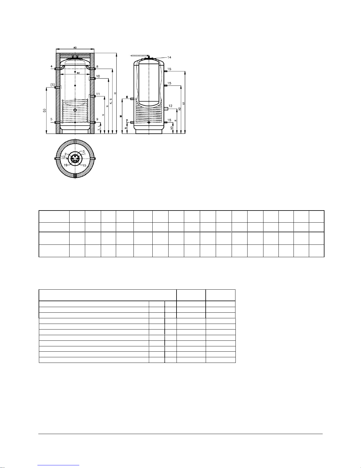
3 Dimensions and connections
Illustration1
Dimensions:
Type
d
D
H
K
L
(L)
M N R S T U V W X1
X2
X3
[mm]
[mm]
[mm]
[mm]
[mm]
[mm]
mm
[mm]
mm
mm
[mm]
mm
mm
[mm]
[mm]
[mm]
WPKR 750
750
950
2000
1610
280
(1150)
865
280
620
1610
280
1370
930
1950
1550
1195
280
WPKR 1000
850
1050
1990
1590
280
(1150)
865
280
580
1590
280
1350
950
1950
1530
1195
280
Chart 1
W = Tilting dimension
Connections:
Type
WPKR
750
WPKR
1000
Cold water / hot water
1/2
Ga ¾ ¾
Circulation
3
Ga ¾ ¾
Aux boiler flow / return
4/5
Ga
5/4
5/4
Solar flow / return
6/7
Gi 1 1
Load flow / return
8/9
Ga
5/4
5/4
Heating flow / return
10/11
Ga
5/4
5/4
Plug for electric heater
12
Gi
6/4
6/4
Vent
13
Gi
1/8
1/8
Inspection flange
14
NW
142
142
Sensor socket
15
Gi ½ ½
Anode
19
Gi ¾ ¾
Chart 2
Ga = male thread
Gi = female thread
Page 4

© Wikora GmbH Page 4 As of 6/22/2015
Errors excepted.
4 Technical data
Description
WPKR 750
WPKR 1000
Capacity heating buffer / DHW
[litre]
ca. 527 / 200
ca. 725 / 200
Max. working temperature buffer / DHW / heat exchanger
[°C]
95 / 95 / 160
95 / 95 / 160
Max. working pressure buffer / DHW / heat exchanger
[bar]
3 / 10 / 10
3 / 10 / 10
Capacity of heat exchanger
[litre]
23
25
Heating area DHW tank
[m²]
2,0
2,0
Surface of heat exchanger
[m²]
2,7
3,0
Flow rate of heat exchanger
[m³/h]
5,0
5,0
Pressure drop of heat exchanger
[mbar]
340
380
Insulation
100 mm fleece insulation
Energy loss
[kWh/24h]
3,9
4,4
Nominal Load N
L
(according to DIN 4708)
ca. 2,9
ca. 2,9
Weight (empty)
[kg]
ca. 240
ca. 280
Chart 3
Page 5

© Wikora GmbH Page 5 As of 6/22/2015
Errors excepted.
5 Installation
All pipes connecting to the tank should have removable connections (fitting/flange). Pipe thread seals with teflon are to
be avoided.
All tank connecting pipes are to be planned, constructed and tested according to the technical rules in force, as well as to the
corresponding norms and regulations in accordance with their application and supply medium.
Appropriate filters should be used to prevent dirt or particles from entering the tanks. Moreover, the tank should be ensured
against pressure fluctuations and excess pressure through the installation of tested pressure reducing valves and safety
valves.
Sensors and thermostats necessary for temperature control must be securely and permanently positioned on the tank
(immersion sleeve and sensor rail).
The tank’s venting and draining facilities must have the appropriate dimensions and be correctly installed.
The installation company is responsible for the correct execution of work and for the safe and careful insulation of the pipes.
When connecting to a solar plant, a temperature limiter is required and must be installed on site at the hot water outlet
in order to prevent scalding.
Safety valve
Drain pipe
Safety group according to
DIN 1988
Stop valve
Stop valve
Manometer connection
Backflow preventer
Test valve
Pressure reducing valve
HW
Circulation
CW
Drain
Water plug
Connection Scheme
Hotwater-
mixer
Anode
Sensorsocket
Illustration 2 (Schematic diagram)
The size of the DHW safety valve is shown below:
Content of DHW space
Min. valve size
Max. heating performance
up to 200 l
NW 15 (1/2“)
75 kW
above 200 to 1000 l
NW 20 (3/4“)
150 kW
When installing a circulation pipe, the plug in the flange cover must be replaced by a circulation connection attachment (plastic
immersion pipe with double nipple R ¾”, Wikora part number 096 090).
The thread diameter of the heating safety valve depends on the nominal capacity of the water space and the maximum heating
capacity of the heat generator. It can be determined as follows:
Reaction pressure
Max. heating capacity of the heat generator
1,5 bar
36 kW
72 kW
144 kW
252 kW
433 kW
650 kW
2,0 bar
43 kW
86 kW
172 kW
302 kW
518 kW
778 kW
2,5 bar
50 kW
100 kW
200 kW
350 kW
600 kW
900 kW
3,0 bar
56 kW
112 kW
224 kW
395 kW
678 kW
1017 kW
Thread diameter (inch)
1/2 ¾ 1
5/4
6/4
2
Illustration 3 (Schematic drawing– example hydraulic system heating)
Page 6

© Wikora GmbH Page 6 As of 6/22/2015
Errors excepted.
6 Commissioning
Before putting into operation, the entire system should be flushed through. Particles in the system compromise the
operating reliability.
When filling the system, fill the DHW tank first and put pressure on it. Open the cold water stop valve and all hot
water nozzles. The tank is full when water leaks out of all hot water nozzles. Then close all nozzles again.
Fill the heating system slowly with water and vent all the air.
Start-up the heating system.
Set the DHW temperature and supervise the system while heating up.
While the System is heating up, water will leak out of the safety valve.
After the tank has heated up and cooled down for the first time, the flange screws must be retightened by
means of a set torque wrench and the flange connection should be checked for tightness.
Torque chart
External diameter of flange/
Diameter of pitch circle
Torque Nm
170 / 145 mm
32 Nm
180 / 150 mm
32 Nm
210 / 180 mm
40 Nm
280 / 245 mm
70 Nm
Before the handover of the system to the end user/owner, the plumbing contractor should ensure that the
system is tested to full load, controls are set and that pipe work and connections are without leaks. Afterwards,
the end user has to be instructed in the operation and handling of the tank, as well as the system. The instruction
must to be documented in the installation and maintenance record.,
Please note that the operation and lifetime of the system depend decisively on a regular maintenance.
7 Maintenance and wear parts
Regular maintenance increases the lifetime and operation reliability of the system. Decalcification at regular intervals may be
necessary in highly calcareous water areas.
1 . Close the cold water stop valve and drain the tank to check the inner tank as well as the heat exchanger. Disconnect any
electrical devices from the appliance. Then, carefully remove the insulation of the flange cover and unscrew the flange
cover. Limescale and rough residues can be crushed by a wooden bar. Only use an approved decalcifier. Screw the
flange cover hermetically after the cleaning process by using a new flange seal. Fill the tank and check all connections for
tightness. Finally, replace the insulation and, if necessary, remount the electrical devices accordingly.
A chemical decalcification can be carried out by a specialist using an approved decalcifier and taking the appropriate
precautions. Please note that the tank must be disconnected from the DHW installation (cold water / hot water /
circulation).
2. For protection purposes, the tank is equipped with a magnesium protection anode. Its transmission depends on the local
water properties. It should be examined for the first time after 2 years and afterwards annually in order to check its
transmission. The diameter should be at least 1/3 of the original diameter, the surface should be homogenous and without
any limescale crust. If necessary, it should be replaced by an original Wikora anode to protect the tank against corrosion.
2.a. Alternatively, the tanks can be equipped with an external current anode. Please note that a protection against
corrosion is only guaranteed if the anode is energized and connected accordingly.
If the protection anode is neglected, this can cause damage through corrosion and lead to a loss of warranty.
3. The safety valve protects the tank against excess pressure. The functional capacity must be checked at regular intervals
by venting. If an expansion vessel is used, the safety valve is not, or only rarely, required. Over a longer period of time
therefore, it can become blocked and not function when needed.
4. If there is a danger of freezing, the DHW tank should be permanently heated or completely emptied.
5. A damp cloth is sufficient to clean the outer parts. Please avoid using any abrasive or solvent cleaning agents.
Page 7

© Wikora GmbH Page 7 As of 6/22/2015
Errors excepted.
8 Warranties and guarantee
Page 8

© Wikora GmbH Page 8 As of 6/22/2015
Errors excepted.
The warranty for our products is based on the legal provisions of the general Civil Code and the Consumer Protection Act.
In addition, defective appliances are replaced within the framework of our full warranty within 1 year, as of the date of the
invoice, including the replacement, procurement and incidental costs. As far as our hot-water heaters and pressurized boilers
are concerned, the warranty amounts for 6 months, as of the date of the invoice.
Subsequent to the full warranty, defective tanks are replaced within the framework of our guarantee. The guarantee of the
different products and the conditions are shown in the table below.
All other claims are excluded. Repairs and costs which occur due to damage, inappropriate installation, chemical,
electrochemical or electrical influences, incorrect operation or improper manipulation, are excluded. Furthermore, the warranty
becomes invalid if th eappliance has been modified through the installation of externally supplied parts or through irregular
professional maintenance.
Subject to our general terms and conditions.
Legal
warranty
2 years
Guarantee
years*
Conditions
WBO T/ToF ● 5 20 / 27
WBL ● 5 20 / 27
WBO Uno ● 5 20 / 27
WBO Duo ● 5 20 / 27
WP/Sol ● 5 20 / 27
WBO H ● 5 20 / 27
GS ● 5 20 / 27
Wikosol Twin ● 10 27
Wikosol ● 10 27
WPKR H Twin ● 5 20 / 27
WPKR Twin ● 5 20 / 27
WPKR ● 5 20 / 27
WPK ● 5 20 / 27
WPH-FW (tank) ● 5 27
WPR-FW (tank) ● 5 27
WPS ● 5 20 / 27
WPH ● 5 WPR ● 5 WPRR ● 5 WKS ● 5 -
Cu-finned tube heat exchanger ● - 27
Electric heating element ● - -
Conditions:
20
27
Coverage Germany:
Compliance with the limits of the valid DHW regulations(TrinkwV 2001), especially the
limits in accordance with Appendix 2, Part 1-2 and Appendix 3
Coverage EU :
Compliance with the limits of the EG-Regulations 83/98
* Start of guarantee at date of invoice
Products
DHW storage tanks
Combi buffer tanks
Buffer tanks
Tank accessories
Under condition that the limits of the valid DHW regulations have been respected, the
anode has been examined for the first time after 2 years and afterwards annually and that
the anode has been replaced by an original Wikora anode (individual receipts needed) by
a specialized company.
Page 9

© Wikora GmbH Page 9 As of 6/22/2015
Errors excepted.
9 Installation record
The installation has been completed according to DIN and the technical rules in force. In addition, the customer has received
instruction concerning the operation and maintenance.
Place……………………………………………….. Date…………………………………………………………
Customer Installer
……………………………………………………. ……………………………………………………………….
Signature Signature
Place of installation: ………………………………………………………………………………………………………………………
Name: ……………………………………………………………………………………………………………………...
ZIP Code/Place: …………………………………………………..………………………………………………………………….
Street: ……………………………………………………………………...………………………………………………
Phone: ……………………………………………………………………………...……………………………………...
Tank model: ………………………………. Serial number …………….………………..………………
Date of invoice ………………………………………………………...…………………………………………………………..
Anode maintenance record
Date
Visual examination of
anode
Exchange of
anode
Signature + stamp of installer
In the case of reclamation, the receipts for maintenance must be provided as proof. Please complete the data sheet, including
the reason for reclamation, and submit to Wikora.
Submitting the maintenance record does not ensure any promise of guarantee or claim.
 Loading...