

WIKORA WPH 300, WPH 2000 Installation Manual
© Wikora GmbH Page 1 As of March 2011
Errors excepted.
WIKORA GmbH
Friedrichstr. 9
89568 Hermaringen
Phone: (07322) 9605-0
Fax: (07322) 9605-30
email: contact@wikora.de
Installation manual
Operating instructions
Heating buffer tank
without heat exchanger
WPH 300 - 2000
Installation and commissioning must be
undertaken by a specialist.
General terms and conditions of warranty state that
all installations must be carried out by a suitably
trained and qualified plumber who observes the
local norms and regulations.
The installation and maintenance record must
be entirely completed and the user has to be
instructed accordingly.
Efficient operation can only be guaranteed if the
instructions of this manual are followed.
Warranty does not cover any damage caused due
to non-observance of this manual and the technical
rules in force.
The system is to be checked annually by a
specialized company. In addition, occurring defects
must be repaired immediately.
This document should be handed over to the
client on completion of the installation.
.
Index
1 General ................................................................................................................................................................................... 2
2 Transport and installation ....................................................................................................................................................... 2
3 Dimensions and connections .................................................................................................................................................. 3
4 Technical data ........................................................................................................................................................................ 4
5 Installation .............................................................................................................................................................................. 4
6 Commissioning ....................................................................................................................................................................... 5
7 Maintenance and wear parts .................................................................................................................................................. 5
8 Warranties and guarantee ...................................................................................................................................................... 6
9 Installation record ................................................................................................................................................................... 7

© Wikora GmbH Page 2 As of March 2011
Errors excepted.
1 General
Depending on the type and design, W IKORA tanks are suitable for heating and / or storing DHW and / or heating water. The
heating is achieved indirectly via heat generators, if applicable, from different heat sources. The maximum working pressure
and working temperature can be found in the technical data.
Set-up, installation and commissioning must be undertaken by a qualified specialist, who must observe these instructions.
The site of installation must be frost-protected according to DIN 4753 and should be in direct proximity to the heat
generator.
When setting-up and installing the tank, the following regulations should be considered:
In addition to the technical rules in force DIN 1988, DIN 18160, DIN 4753, DIN 4109, DIN 4708, DIN 4751 section 2-4 energy
conservation law and VDE regulations are to be observed. Moreover, the relevant regulations of the suppliers as well as legal
building regulations are to be considered.
Important: The exhaust pipe must be at least as big as the safety valve outlet in width. It may not have more than 2 bends and
should not be longer than 2 m. If for any compelling reasons 3 bends or a length up to 4 m are required, then the entire exhaust
line must be designed one nominal size larger. More than 3 bends, or a length exceeding 4 m is prohibited. The exhaust pipe
must be installed with downward gradient. The drain line behind the funnel must feature at least the double width of the valve
entrance. A sign is to be attached close to the exhaust pipe of the safety valve or on the safety valve itself. „For safety reasons
water may leak from the exhaust pipe during the heating process! Do not lock! "The operability of the safety valve is to be
checked at regular intervals by means of de-ventilation.
2 Transport and installation
In order to prevent damage during transport, the packaging should only be removed at the site of installation. During shipment,
it should be ensured that the tank does not come in contact with any spiky or sharp items, nor is damaged through dropping or
knocks.
During installation, the tank must be disconnected from any humidity carrying components. Moreover, sufficient space for
maintenance and cleaning purposes should be kept free in front of, beside, above and behind the tank.
Please note that the insulation provided should be kept in a dry place at least 24 hours at a minimum temperature of
20°C before installation.
© Wikora GmbH Page 3 As of March 2011
Errors excepted.
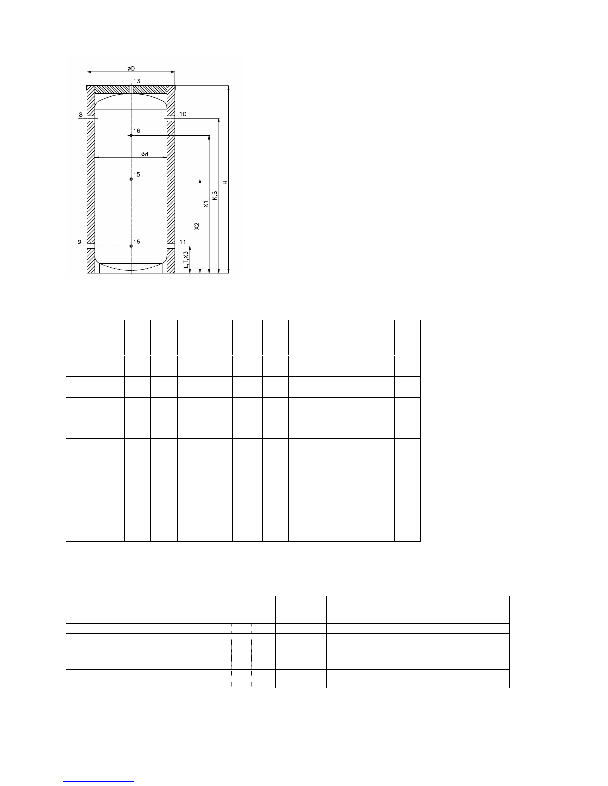
3 Dimensions and connections
Illustration
1
Dimensions:
Type
d D
H K L S T W X1 X2 X3
[mm] [mm] [mm] [mm] [mm] [mm] [mm] [mm] [mm] [mm] [mm]
WPH 300
550 710 1550 1230 230 1230 230 1570 1100 800 230
WPH 400
600 760 1630 1300 245 1300 245 1650 1150 850 245
WPH 500
600 760 1960 1630 245 1630 245 1980 1450 950 245
WPH 750
750 910 1970 1610 280 1610 280 2000 1430 980 280
WPH 825
790 950 1905 1560 280 1560 280 1950 1480 940 280
WPH 980
790 950 2175 1830 280 1830 280 2200 1750 1060 280
WPH 1000
850 1010 1920 1590 280 1590 280 1980 1485 940 280
WPH 1500
1000 1160 2130 1710 340 1710 340 2180 1600 1000 340
WPH 2000
1200 1400 2090 1620 370 1620 370 2200 1400 1010 370
Chart 1
W = Tilting dimension
Connections:
Type WPH
300 / 400
WPH
500/750/825/980
WPH
1000
WPH
1500 /
2000
Load flow 8 R 1 5/4 5/4 2
Load return 9 R 1 5/4 5/4 2
Heating flow 10 R 1 5/4 5/4 2
Heating return 11 R 1 5/4 5/4 2
Vent 13 Rp 1 1 2 2
Sensor socket 15 Rp ½ ½ ½ ½
Thermometer socket 16 Rp ½ ½ ½ ½
Chart 2
R = male thread
Rp = female thread
 Loading...