

Page 1

© Wikora GmbH Page 1 As at November 2013
Errors excepted.
WIKORA GmbH
Friedrichstr. 9
89568 Hermaringen
Phone: (07322) 9605-0
Fax: (07322) 9605-30
email: contact@wikora.de
Installation manual
Operating instructions
Gas Boiler
GS 117 E / GS 152 E / GS 192 E
Installation, calibration and commissioning
must be undertaken by a specialist.
The boiler must be connected according to the
regulations in force and may only be operated in
well vented areas.
Control devices must be checked for functioning.
Fittings, immersion sleeves, connection seals, drain
valve etc must be checked and if necessary
retightened or resealed.
General terms and conditions of warranty state that
all installations must be carried out by a suitably
trained and qualified plumber who observes the
local norms and regulations.
The installation and maintenance record must
be entirely completed and the user has to be
instructed accordingly.
Efficient operation can only be guaranteed if the
instructions of this manual are followed.
Warranty does not cover any damage caused due
to non-observance of this manual and the technical
rules in force.
The system is to be checked annually by a
specialized company. In addition, occurring defects
must be repaired immediately.
This document should be handed over to the
client on completion of the installation.
.
Index
1
General ................................................................................................................................................................................ 2
2
Transport and installation .................................................................................................................................................... 2
3
Dimensions and connections .............................................................................................................................................. 3
4
Technical data ..................................................................................................................................................................... 4
5
Installation ........................................................................................................................................................................... 5
6
Commissioning .................................................................................................................................................................... 7
7
Gas regulation ..................................................................................................................................................................... 8
8
Conversion to other gas types ............................................................................................................................................. 9
9
Technical data - Gas ......................................................................................................................................................... 10
10 Convertion kits .................................................................................................................................................................. 10
11 Maintenance and wear parts ............................................................................................................................................ 11
12 User Information ............................................................................................................................................................... 11
13 Faults ................................................................................................................................................................................ 11
14 Warranties and guarantee ................................................................................................................................................ 13
15 Installation record ............................................................................................................................................................. 14
Page 2

© Wikora GmbH Page 2 As of November 2013
Errors excepted.
Security advice
When smelling gas
• close gas tap
• open the window
• don’t operate any electric switch
• extinguish open flames
• call (from outside) gas company and authorized specialist
When smelling exhaust gas
• disconnect appliance
• open windows and doors
• call authorized specialist
Explosive and readily flammable material
• Don’t use or store any readily flammable material (paper, thinner, paint etc.) in direct proximity to the appliance.
Combustion air / Ambient air
• Keep combustion air / ambient air free from aggressive substances (e.g. halogen carbon dioxide, hydroxide
containing chlorine or fluorine compounds) to avoid corrosion
1 General
The standing gas boiler is a direct fired multi-gas appliance. It is suited for a maximum working pressure of 10 bar and a
maximum working temperature of 70°C. The pressure resistant boiler can supply several tap connections at the same time.
The flue gas must be dissipated through an authorized flue gas system.
A baffle plate mounted to the flue gas pipe of the tank guarantees an excellent heat transmission. The burner unit consists of a
main burner and pilot burner, control fittings with piezo spark ignition, thermoelectric safety pilot, temperature control as well as
a gas pressure regulator and can be converted to natural gas and liquid gas according to the DVGW process sheet G 260. 2
measuring devices have been fitted at the control unit to regulate pressure in nozzles and connecting pipes. The desired water
temperature can be regulated at the temperature control button. In case of overheating the build in temperature stop control
will cut off the electricity supply at circuit.
The tank is protected against corrosion by double-coated enamel and magnesium anode. An insulation layer between the
internal tank and the steel plate housing minimizes loss of heat. The steel plate housing is lacquered.
The burner unit can be removed at the front for cleaning and maintenance purpose. The tank may only be operated with an
installed protection anode.
Installation, calibration, commissioning and maintenance must be undertaken by a specialist.
For the installation, the following regulations should be considered: DIN 18160, DIN 4753, DIN 4109, DVGW TRGI 2008, TRF
1996/97 Part 1 and 2, DIN 1988, the relevant regulations of the suppliers as well as the local legal building regulations in force.
All tank connecting pipes are to be planned, constructed and tested according to the technical rules in force, and the
corresponding norms and regulations in accordance with their application and supply medium.
2 Transport and installation
In order to prevent damage during transport, the packaging should only be removed at the site of installation. During shipment,
it should be ensured that the tank does not come in contact with any spiky or sharp items, nor is damaged through dropping or
knocks.
Always place in a frost free but cool area and close to the chimney. The size of the room and the ventilation necessary is
subject to DVGW-standards. Avoid under all circumstances rooms with any kind of aggressive fumes (propellant, glue, solvents
etc.) as these can cause corrosion in the exhaust system and can lead to combustion or explosion. Cover wooden or synthetic
floor with fire resistant insulator. The tank must be disconnected from any humidity carrying components. Any light flammable
material must be placed at least one meter away. Moreover, sufficient space for maintenance and cleaning must be kept
unobstructed at the front, the sides, above and behind the boiler.
Page 3
© Wikora GmbH Page 3 As of November 2013
Errors excepted.
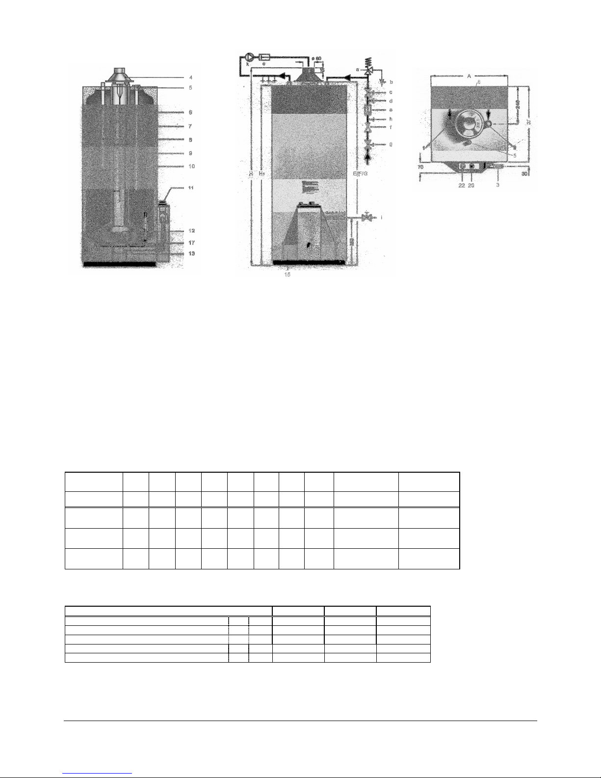
3 Dimensions and connections
Illustration1
1 Hot water connection R 3/4
2 Cold water connection R 3/4
3 Gas connection Rp 1/2
4 Flow operated safety device
5 Anode
6 Baffle plate
7 Water tank
8 Circulation immersion pipe R ¾ (Accessory)
9 Insulation
10 Casing
11 Control fittings
12 Main burner
13 Pilot burner
15 Cover plate
17 Drain
20 Temperature control button
22 Piezo spark ignition
a Diaphragm - safety valve min. DN 15
b Drain pipe
c Water stop valve
d Manometer- connection nozzle
e Backflow preventer
f Pressure reducing valve if more than 8 bar connection pressure
g Water stop valve
h Test valve
i Gas stop valve
k Circulation pump
Dimensions:
Type A B C E F G H H1
Height
gas connection
Diameter tube
flue gas
[mm] [mm] [mm] [mm] [mm] [mm] [mm] [mm] [mm] [mm]
GS 117 E
480 480 224 1140 1140 1140 1208 1100
303 80
GS 152 E
480 480 224 1396 1396 1396 1464 1356
303 80
GS 192 E
480 480 224 1713 1713 1713 1781 1673
303 80
Chart 1
Connections:
Type GS 117 E GS 152 E GS 192 E
Cold water / hot water 1/2 R ¾ ¾ ¾
Circulation 3 R ¾ ¾ ¾
Drain 17 Rp ½ ½ ½
Gas connection 18 Rp ½ ½ ½
Anode 19 Rp ¾ ¾ ¾
Chart 2
R = male thread
Rp = female thread
Page 4

© Wikora GmbH Page 4 As of November 2013
Errors excepted.
4 Technical data
Type GS 117 E GS 152 E GS 192 E
Capacity
[liter] ca. 115 ca. 150 ca. 190
Max. working pressure
[bar] 10 10 10
Output
[kW] 7,12 8,12 9,18
Input (gross)
[kW] 8,0 9,1 10,2
Flue gas temperature
[°C] 155 171 171
Flue gas volume [kg/h] 18,3 19,7 21,5
Flue draft requirement
[mbar] 0,04 0,04 0,04
CO2 by volume
[%] 6,4 6,8 7,0
Time to recover from 10°C to 60°C [ca. min] 52 61 67
Energy loss
[kWh/24h] 4,08 4,85 5,04
Continuous output DHW of 45°C
[l/h] 175 200 226
Hot water starting efficiency
[ca. l/10 min] 160 205 266
Gas consumption
Natural gas group E H
uB
9,4 kWh/m3
[m3/h] 0,85 0,97 1,09
Natural gas group LL H
uB
8,5 kWh/m3
[m3/h] 0,94 1,07 1,20
Liquid gas (propane) H
uB
12,8 kWh/kg
[kg/h] 0,63 0,71 0,8
Nominal Load N
L
(70°)
ca. 1,7 ca. 2,7 ca. 3,4
Weight (empty)
[kg] ca. 65 ca. 80 ca. 90
Chart 3
Necessary flow pressure for gas connection
Natural gas 18 mbar – 25 mbar
Liquid gas 50 mbar +/- 5 mbar
If the flow pressure for gas connection is outside those values, an installation is prohibited (see 6.1, 3 ff)
Gas (at 15°C, 1013 mbar)
according to CE-Norm according to DVGW
E (G20) Wobbeindex: 11,3 – 15,2 kWh/m³ N (H) Wobbeindex: 12,0 – 15,7 kWh/m³
LL (G25) Wobbeindex: 9,5 – 12,4 kWh/m³ N (L) Wobbeindex: 10,5 – 13,0 kWh/m³
P (G31) Wobbeindex: 20,3 – 21,3 kWh/m³ F Wobbeindex: 22,1 – 25,81 kWh/m³
Page 5

© Wikora GmbH Page 5 As of November 2013
Errors excepted.
5 Installation
5.1 Water connection
Erect boiler vertically and straight with the aid of a spirit level and if necessary place metal strips underneath. Water
connections should have removable connections and must be checked for tightness. A safety group must be installed in the
cold-water connection and if water pressure is above 8 bar a pressure reducing valve is to be installed. Appropriate filters
should be used to prevent dirt or particles from entering the boiler.
The safety valve must be set at 10 bar excess pressure and must be tested and executed at least with DN 15. It is to be
installed in the cold water connection and must not be cut off through the hot water tank. It must be well accessible for control
purpose. The functional capacity of the safety valve in the cold water connection must be checked at regular intervals by
venting.
The exhaust pipe must be at least as big as the safety valve outlet in width. It may not have more than 2 bends and should not
be longer than 2 m. The exhaust pipe must be installed with downward gradient. It must be ensured that people cannot be
endangered by escaping hot water or steam.
The drain line behind the funnel must feature at least the double width of the valve entrance. The exhaust pipe and drain pipe
must be protected against freezing and should not lead outside.
A sign is to be attached close to the exhaust pipe of the safety valve or on the safety valve itself. „For safety reasons water
may leak from the exhaust pipe during the heating process! Do not lock!”
To avoid an excessive loss of water an appropriated expansion valve can be installed between the tank and the safety valve
inside the cold water pipe.
5.2 Circulation pipe
Should a circulation pipe be necessary it must be carefully insulated for economical reasons. To ensure a flawless and energy
saving functioning, the circulation pipe must be fitted at the tank only with an original connection attachment (available as
spare parts) at the connection point. Connect the circulation pump and reverse flow stopcock between warm water supply and
circulation connection. The circulation pump should be regulated through thermal control (Pump should only start operation
when the temperature in the circulation falls beneath 30° C) to keep operating cost low. Should no circulation be needed
during the night an extra time control switch is recommended to turn off the circulation pump.
5.3 Gas connection
The gas connection is to be fitted at the front of the control fittings in adequate dimension and only after having cleared the
pipe by blowing through and airing. Contamination of the control fittings through dirt and thickening materials must be avoided.
The stopcock for the gas is to be fitted on site and has to be at least NW1/2’. The connections must be checked for tightness.
Checked pressure max. 50mbar (500mm WS). Should it be necessary to use more pressure to check for leaks in the gas
connection pipe then the gas connection pipe is to be removed from the control unit.
5.4 Exhaust connection
Check chimney for suitability to transport exhaust fumes. Cross section and durability have to
comply with DVGW-TRGI regulations.
Check if pipe sockets (b) are still correctly fitted with the baffle plate (d) in the exhaust pipe.
The pipe sockets have to be pushed into the exhaust pipe up to their bulge.
At first installation: remove cover plate (15) and cap (a) with screws from the base. Place cap (a)
onto pipe sockets (b) and fix securely with 3 screws (c).
Connect corrosion resistant exhaust pipe airtight at the pipe sockets of the flow operated safety
device. Place exhaust pipe elevating towards the chimney at shortest possible distance. It must
not penetrate the cross section of the chimney. The distance needed between the flows operated
safety device and the exhaust bend to the chimney must be no less than 160mm. No covers are to
be placed over nor are any alterations to be made to the flow operated safety device.
Illustration 2
Page 6
© Wikora GmbH Page 6 As of November 2013
Errors excepted.
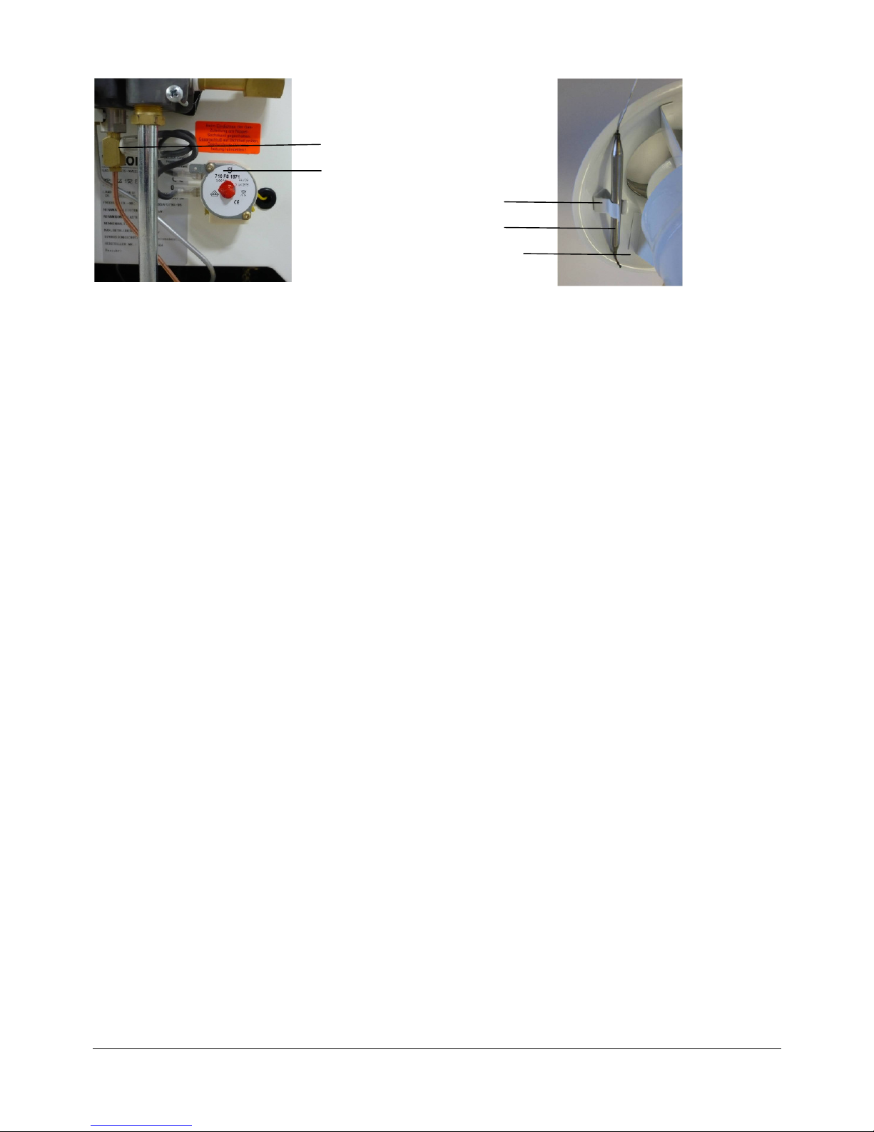
5.5 Flue gas sensor
Thermal switch
Flue gas controller
Sensor clamp
Thermal sensor
Flow operated safety device
Warning: The flue gas sensor must never be disconnected.
Installation
Carefully lift thermal sensor and clip to the sensor clamp at the cap of the flow operated safety device. Avoid bending the
capillary tube in the process. A seal is to be placed over the thermal sensor to avoid slipping or even unauthorized removal.
Operating instructions
The contact in the thermostat of the flue gas controller is integrated in the thermal electrical circuit. Should over a prolonged
period of time exhaust fumes escape at the flow operating safety device, the flue gas sensor interrupts the thermal electrical
circuit and cuts off the gas supply automatically. After a period of 5 minutes switch the gas-boiler can be put again into
operation (see commissioning No. 6ff) .
Should the appliance cut off several times via the flue gas sensor, a specialist is to be called in order to check the boiler and
the exhaust system (see list of faults p. 12).
Operating control
To check the flue gas sensor, proceed as follows: Close completely the exhaust pipe with the help of cloth and other such
materials at the first connection point behind the flow operated safety device. After commissioning, a complete drop out of
exhaust fumes will take place at the flow operated safety device. The flue gas sensor must then cut off the gas supply after only
2 minutes. This check should be carried out swiftly and the area needs to be aired sufficiently (danger of suffocation).
5.6 Exhaust fume cap
By installation of a flue gas damper only use Diemayer-damper HOK 80 W DIN-DVGW-Reg.-No. 86.02e 003! (Wikora part
number 090062).
Page 7
© Wikora GmbH Page 7 As of November 2013
Errors excepted.
6 Commissioning
6.1 First commissioning
In order to fill the tank and vent all the air, open the cold water stop valve and all hot water nozzles. The tank is filled and all
pipes are vented when water leaks out of all hot water nozzles. Then close all nozzles again and check all water-bearing parts
on tightness.
Check if the appliance is correlating with the type of gas available. If this is not the case, convert as shown on page 9. If the
type of gas is correct proceed according to page 8.
6.2 Commissioning and operating
Before any commissioning and operating check that the hot water tank is filled. Open the cold water stop valve and all hot
water nozzles. The tank is filled and all pipes are vented when water leaks out of all hot water nozzles. Then close all nozzles
again. Moreover, the functional capacity of the safety valve must by checked by venting.
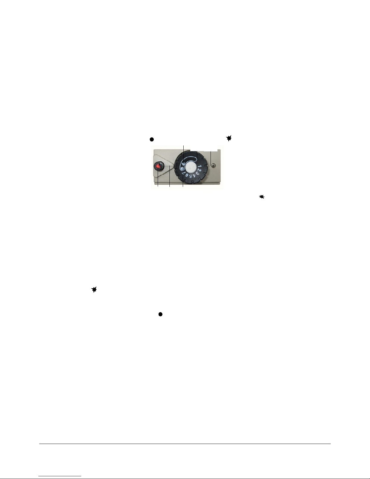
6.3 Prepare for use
1. Open gas safety valve at the appliance.
2. Switch temperature control button from OFF (24) to full stop at ignition mark (23).
3. Push temperature control button (20) several times at the same time as piezo spark ignition (22) till pilot flame appears.
Once the pilot flame is burning, press the temperature control button a further 20 seconds, then release. Should the pilot
flame go out, repeat ignition procedure after 5 minutes.
4. Turn temperature control button to the desired water temperature. The most economical setting is between 5 and 6 (60*C).
Due to lime scale damage is setting 7 (ca 70 *C) only to be used for short periods. (Number scale and dial marking 26 to
be assimilated).
5. The main flame operates when the chosen temperature is higher than the actual water temperature in the tank. The
appliance is working automatically. The gas control fittings will switch off or on the main burner depending on the water
temperature. At the moment the appliance is switched on again the gas will be ignited by the constantly burning pilot flame.
6.4 Temporary interruption (Stand-by-Position)
If the main burner should be kept switched off and only the pilot flame remains burning, the temperature control button must be
turned to ignition mark .
6.5 Switch off
1. Turn temperature control button to OFF position (24) and close the gas stop valve at the appliance
Attention: The switch on lock prevents the re-ignition of the appliance during the safety time of 60 seconds.
2. If the appliance is kept off for a longer period of time, close the water stop valve and the gas stop valve. Keep appliance
running in frosty conditions or empty tank after closing gas supply.
6.6 Emptying
Switch off any gas connection at the hot water tank. Let the content of the tank cool down. Close the cold water stop valve at
the cold water supply and open the nearest hot water nozzle. Empty tank through drain valve and close drain valve afterwards.
Refill with water before any further use. (see commissioning).
6.7 Condensation
As the tank gets heated up from a cold state to a temperature of about 48°C, condensation will occur quite naturally on warmed
surfaces. At times, this condensation was incorrectly thought to be caused by a leak in the tank. Therefore, to check the tank
and the water connections on tightness ensure that the tank is not heated and that full water pressure is resumed. The
construction ensures an effective compensation of the condensate, avoids any disturbing effect caused by flames and
functioning and protects against corrosion.
It is recommended to keep the tank operated outside the noticeable condensate area between position 5 and 6 which
corresponds to ca. 60° C.
22
23
26
24
Page 8

© Wikora GmbH Page 8 As of November 2013
Errors excepted.
7 Gas regulation
All appliances are compliant with the kind of gas shown on the additional sticker “Type of gas” placed on the appliance. Should
other gas be used the appliance is to be adjusted accordingly (see page 9). The performance of the appliance is to be set
according to the nozzle pressure method or the volumetric method. This is only to be undertaken by a recognized specialist.
Both methods require a U-tube-manometer.
Remark: The nozzle pressure method is more time-saving and therefore the preferred option. If operated with liquid gas the
regulation of the nominal load is obsolete. It is sufficient to check the flame according to DVGW-TRF regulations. All flames
have to be burning uninterrupted and with as little green core as possible and not beat back. W hen liquid gas is used the
connection pressure is to be monitored and regulated at the separate pressure measure device on the gas supply unit. It has to
be at 50 mbar + 5 mbar.
7.1 Nozzle pressure regulation method
Wobbe-Index W0 and net heating value HuB to be requested from the gas supply company.
1. Take off cover plate (15), pressure adjusting screw at measure nozzle (30) and connect U-tube-manometer.
2. Open gas stop cock and put appliance into operation (see page 7).
3. Read existing connection flow pressure at U-tube-manometer. For natural gas, the connection flow pressure should
be between 18 mbar and 25 mbar.
4. Should the connection flow pressure vary from the above mentioned values, the cause needs to be established and
the fault to be rectified. Should this not be possible, the gas supplier needs to be contacted.
5. Switch the temperature control (20) button to OFF (24). Take off the U-tube-manometer only when gas stop cock is
closed. Screw in screw of the measure nozzle (30) gas tight.
6. Remove screw of the measure nozzle (21) and connect U-tube-manometer.
7. Open gas stop cock and put appliance into operation according to „Commissioning“ (page 7).
8. Check that the water temperature in the tank is not higher than lukewarm to 50°C, cool by emptying some water if
necessary. Turn temperature regulation button (20) to position “6”.
9. Take off cover cap (25) and adjust the die pressure that is stipulated in the table on page 10 by turning the pressure
adjusting screw (17) of the pressure regulator (14). The die pressure is increased by turning to the right and
decreased by turning to the left. Replace the cover cap (25) and put the screws in place.
10. Turn the temperature control button (20) to OFF position. (Align marking (24) with marking (26)). Close gas stop
cock, remove U-tube-manometer and screw in the screws of the measure nozzle (21) gas tight.
11. Check if the right nozzle has been used and then proceed with a rough check on the gas meter in l/min (see gas flow
rate table 9.2). Do not adjust the die pressure if the discrepancy of the rough count represents less than 10% of the
value of gas consumption in l/min shown in the gas flow rate table. If the gap is larger than 10%, the die pressure is
not correctly set.
12. Safety check: Close gas stop cock for 20 – 45 seconds. The safety pilot should audibly close after the gas stop cock
has been closed.
13. Replace cover plate (15).
7.2 Volumetrische Methode
14 Pressure regulator
17 Pressure adjusting screw
20 Temperature control button
21 Measure nozzle for die pressure
22 Button for piezo spark ignition
22a Piezo spark ignition
23 Marking for ignition setting
24 Marking for OFF position
25 Cover cap
26 Marking for temperature control button
29 Gas connection flange ½“
30 Measure nozzle for connection pressure
31 Thermal power line
32 Gas supply from main burner
33 Ignition gas line
34 Ignition cable
36 Capillary tube for temperature sensor
24 26 22
23 25
20
17
14
22
Page 9

© Wikora GmbH Page 9 As of November 2013
Errors excepted.
7.2 Volumetric method
Only possible if no extra gas is pumped into the net by the GVU.
Wobbe-Index W0 and net heating value HuB to be requested from the gas supply company.
1. Take off cover plate (15), pressure adjusting screw at measure nozzle (30) and connect U-tube-manometer. Open gas
stop cock and put appliance into operation (see page 7).
2. Read existing connection flow pressure at U-tube-manometer. For natural gas, the connection flow pressure should be
between 18 mbar and 25 mbar.
3. Should the connection flow pressure vary from the above mentioned values, the cause needs to be established and the
fault to be rectified. Should this not be possible, the gas supplier needs to be contacted.
4. Open gas stop cock and put appliance into operation according to „Commissioning“ (page 7).
5. Check that the water temperature in the tank is not higher than lukewarm to 50°C, cool by emptying some water if
necessary. Turn temperature regulation button (20) to position “6”.
6. Adjust the die pressure that is stipulated in the table on page 10 by turning the pressure adjusting screw (17) of the
pressure regulator (14). The die pressure is increased by turning to the right and decreased by turning to the left.
7. Turn the temperature control button (20) to OFF position and close gas stop cock
8. Safety check: Close gas stop cock for 20 – 45 seconds. The safety pilot should audibly close after the gas stop cock has
been closed.
9. Switch the temperature control (20) button to OFF (24). Take off the U-tube-manometer only when gas stop cock is
closed. Screw in screw of the measure nozzle (30) gas tight.
10. Replace cover plate (15).
8 Conversion to other gas types
Any conversion is only to be undertaken by a registered specialist.
8.1 From natural gas to liquid gas
8.1.1. Close gas stop cock and remove cover plate (15).
8.1.2. Remove burner unit: Loosen screws for the gas supply line (32), ignition gas line (33) and thermal power line (31) at
the regulator. Lift the burner unit from the 2 centre bolts at the support and move everything slightly forward. Now
place on bottom tray and remove.
8.1.3. Exchange main nozzle (40). For nozzle diameter see table on page 10.
8.1.4. Loosen screws (41) of the ignition gas line (33) at the pilot burner (13) and exchange nozzle. The nozzle number can
be found in the table on page 10. Re-attach the ignition gas line (33) gastight by using the screws (41).
8.1.5. Relocate burner unit on centre bolts. Screw back gas supply line (32) and ignition gas line (33) onto the regulator and
make sure that it is gastight. Screw back the thermal power line (31) hand tight.
8.1.6 Remove cover cap (25). Remove pressure regulator (14) and replace with maximum set screw No. 228. The die
pressure is about equal the connection pressure.
8.1.7. Open gas stop cock and check pipes and gas fittings on tightness. Replace cover cap (25) and fix screws.
8.1.8 Close gas stop cock
8.1.9. Place new sticker „Type of gas“ on the gas fittings.
8.1.10 Replace cover plate (15).
8.2 From liquid gas to natural gas
8.2.1. Follow points 8.1.1 till 8.1.5
8.2.2. Remove cover cap (25). Remove maximum set screw No. 228 and
install pressure regulator (14). Set nominal load according to “Gas
regulation“ (page 8).
8.2.3. Follow points 8.1.7. till 8.1.10
8.3 From natural gas group E to natural gas group LL or vice versa
8.3.1 Close gas stop cock and remove cover plate (15).
8.3.2. Remove cover cap (25).
Set nominal load according to “Gas
regulation“ (page 8). Replace cover cap (25) and fix screws.
8.3.3 Place new sticker „Type of gas“ on the gas fittings.
8.3.4 Replace cover plate (15) and open gas cock.
Page 10

© Wikora GmbH Page 10 As of November 2013
Errors excepted.
9 Technical data - Gas
9.1 Die pressure table GS 117 E / GS 152 E / 192 E
Type GS 117 E GS 152 E GS 192 E
Output 7,12 KW 8,12 KW 9,18 KW
Input (gross) 8,0 KW 9,1 KW 10,2 KW
Gas type
Wobbe-
Index
Pilot
burner
nozzle
Nozzle pressure
[mbar]
at nominal load
Main
burner
nozzle
Nozzle pressure
[mbar]
at nominal load
Main
burner
nozzle
Nozzle pressure
[mbar]
at nominal load
Main
burner
nozzle
kWh/m³ No. No. No. No.
Natural
gas group
LL
12,4 27 8,8 280 11,2 280 10,1 300
Natural
gas group E 15,0 27 8,2 260 10,5 260 7,0 300
Liquid gas
(propane)
25,7 023 50 115 R 50 120 R3 50 130 R1
9.2 Gas flow rate table GS 117 E / GS 152 E / 192 E
Type GS 117 E GS 152 E GS 192 E
Output 7,12 KW 8,12 KW 9,18 KW
Input (gross) 8,0 KW 9,1 KW 10,2 KW
Gas type
Net heating
value H
*)
Gas volume [l/min.]
at nominal load
Gas volume [l/min.]
at nominal load
Gas volume [l/min.]
at nominal load
kW h/m³
Natural gas
group LL
8,5 15,5 17,6 19,8
Natural gas
group E
9,4 14,1 16,1 18,0
Liquid gas
(propane)
27,7 4,8 5,4 6,1
*Net heating value HUB at gas volume at 15°C, 1013 mbar dry.
10 Conversion kits
GS 117 E / GS 152 E /GS 192 E- execution with gas fittings EUROSIT 630, stainless steel burner and LOW-Energy-pilot
burner.
GS 117 E GS 152 E GS 192 E
Item Part No Quantity
Natural gas Group E Part No 39 12 21 39 12 21 39 82 21
Burner nozzle
Ø 2,6 mm, No 260 03 91 21 1 1 Ø 3,0 mm, No 300 03 96 32 - - 1
Ignition Nozzle No 27 39 54 60 1 1 1
Pressure regulator 03 95 18 1 1 1
Natural gas Group LL Part No 39 92 21 39 92 21 39 92 22
Burner nozzle
Ø 2,8 mm, No 280 03 95 32 1 1 Ø 3,0 mm, No. 300 03 97 32 - - 1
Ignition Nozzle No 27 39 54 60 1 1 1
Pressure regulator 03 95 18 1 1 1
Liquid gas Group P 50 mbar Part No 03 91 31 39 83 10 39 93 10
Burner nozzle
Ø 1,15 mm, No 115R 39 13 31 1 Ø 1,20 mm, No 120R3 03 96 33 1
Ø 1,30 mm, No 130R1 03 97 33 - - 1
Ignition Nozzle No 023 39 54 62 1 1 1
Maximum set screw 03 95 19 1 1 1
Page 11

© Wikora GmbH Page 11 As of November 2013
Errors excepted.
11 Maintenance and wear parts
According to the regulations for gas operated burner units the end user has to have the appliance checked every year by a
qualified specialist. Only original spare parts are to be used. The following work needs to be done:
1. Check safety anode for wear and tear. When heavy wear occurs, a new original safety anode is to be fitted to
protect the tank against corrosion.
2. Check ignition safety valve: Close gas stop cock for 20 – 45 seconds. The safety pilot should audibly close after the
gas stop cock has been closed.
3. Clean gas filter at the entrance of the control fittings
4. Clean pilot burner and main burner. (Removal and fitting of burner units can be found on page 9 „Conversion to other
gas types“
5. Clean baffle plate (6), fire tube and combustion chamber with a brush.
6. Rinse vessel with fresh water
7. Check temperature limiter in water or similar. It needs to switch off at 92 + 3 C
8. Check the plastic pipes for cold and warm water as well as possibly circulation connections and exchange when
damaged.
9. W hen cleaning is finished, prepare the appliance for use. Check safety valve at the cold water supply by venting and
check all gas and water carrying devices on tightness. Put the appliance into operation. Check gas setting (see page
8 section „gas regulation).
10. Check flue gas evacuation.
12 User Information
The boiler is a quality appliance. It is tested and approved according to the current regulations regarding energy efficiency,
presser safety and operational safety. It can be adjusted to natural gas and liquid gas and has an increase pressure safety
(10bar). It has a long life expectancy. This is because the high quality enamel application takes place directly at the already
welded boiler which guaranties an all round protection against corrosion.
Installation, calibration and commissioning must only to be undertaken by a registered and qualified specialist, approved by
the gas board. Any fault can be identified according to the fault-identification list. The specialist will inform the customer on
how the appliance is used and how it works. The customer is also to be informed of the importance of regular maintenance
and that this is a decisive factor as to how long the appliance will last. Openings necessary to allow air circulation around the
site of installation must not to be reduced nor closed. Exhaust parts must not be altered in any way. The customer is not
permitted to undertake any alterations or maintenance issues.
The boiler temperature can be regulated with the temperature control button (20). High temperatures are only to be run for
short periods of time (lime scale build up). Chose a setting between 4 and 5, about 60° C for an economic and hygienic (e.g.
legionella) running. In buildings with long pipe works – e.g. hospitals, old people’s homes, hotels and blocks of flats – the
water temperature has to be set at 60° C. This also applies to installations with more than one boiler, should they have a
combined water volume of more than 400 liters.
In frosty weather or if frost is expected, the appliance is either to be kept running or emptied completely.
12.1 Commissioning and handling
See point 6.
12.2 Care
A damp cloth is sufficient to clean the outer parts. Please avoid using any abrasive or solvent cleaning agents. Before putting
the tank into operation but also during operation, the functional capacity of the safety valve must by checked at regular
intervals by venting. When working correctly, water will run out at full blast.
12.3 Maintenance
The end user has to have the appliance cleaned and checked on its impeccable functioning annually by a qualified and
registered specialist and according to the regulations regarding gas-operated appliances. Occurring defects must be repaired
immediately. Before any intervention make sure that the stop cocks for gas and water are closed.
Any maintenance work to be carried out can be found in section 11. Should it not be possible to establish the cause of any
fault, inform customer services, the sales representative or the company with all findings. Please indicate in that case the
technical data on the performance sticker.
13 Faults
A member of our customer service team is always happy to assist you with any fault. However, should the fault lie with the user
or the installer, then the costs have to be passed on. This also applies during the period when the appliance is still covered
under warranty. In case of warranty the company will cover the costs raised by customer services.
Page 12

© Wikora GmbH Page 12 As of November 2013
Errors excepted.
13.1 List of faults
Fault Cause Rectification
by
I = Installer B = User
K = Customer services
1) CO to high in exhaust
fumes
Appliance not set to nominal load I Set nominal load (according to page 8 ff) to correct
nozzle pressure – or gas flow rate
Main burner unit not correctly placed I Place main burner unit correctly
2) Strong condensation
(see page 7)
Appliance not set to nominal load I Set nominal load (according to page 8 ff) to correct
nozzle pressure – or gas flow rate
Baffle plate not placed or incorrectly placed I Place baffle plate correctly (see page 5)
Appliance is constantly run in condensation area (till
50° C)
B Set temperature control button higher to setting 4 till
5 (red dot). This corresponds to ca. 60°C.
Wrong main burner nozzle installed I Change nozzle (see page 10 nozzle pressure table)
3) Water in the bottom tray Connections not tight I Check all connections on tightness (see page 5)
Strong condensation see point 2)
4) Pilot flame can‘t be lit Temperature control button not pressed deeply
enough
B Press temperature control button fully (see page 7)
Pilot nozzle dirty I Clean pilot nozzle
Installed pilot nozzle is too small I Install correct burner nozzle according to die pressure
table on page 10
5) Pilot flame will not spark
although gas is flowing
Piezo spark ignition defect I Replace piezo spark ignition
Ignition cable defect I Replace ignition cable
Spark plug defect I Replace spark plug
6) Pilot flame extinguishes
after release of starter button
Thermal element not heated yet B Keep temperature control button longer pressed after
ignition (see page 7)
Screws of the thermal element at the control fittings
not correctly tightened.
I Tighten carefully, connection has to be dry and clean
(see page 8)
Thermal element not correctly fitted at ignition
burner
I Place thermal element fully in support at pilot burner
so that pilot flame can heat up thermal element.
Thermal element defect I Replace thermal element
Magnet in gas regulator broken K Replace gas control fittings
Flue gas sensor defect I Replace flue gas sensor
7) Pilot flame extinguishes
when changing from pilot
flame to main flame
Flow pressure for gas connection far too low ( gas
connection from the system far too small,
connection pipe blocked, filter blocked)
I Check gas supply, adjust dimensions of gas pipes,
clean connecting pipes, clean dirt filter.
Ignition nozzle blocked I Clean ignition nozzle
The installed ignition nozzle is too small I Install correct burner nozzle according to die pressure
table on page 10
Baffle plate not placed or incorrectly placed I Place baffle plate correctly (see page 5)
Nominal load set too high (appliance is overloaded) I Set nominal load (according to page 8 ff) to correct
nozzle pressure – or gas flow rate
8) Not enough hot water Temperature control button not set at correct
temperature
B Adjust temperature control button to correct
temperature
Baffle plate not placed or incorrectly placed I Place baffle plate correctly (see page 5)
Nominal load set too low I Set nominal load (according to page 8 ff) to correct
nozzle pressure – or gas flow rate
Temperature control button defect K Replace gas control fittings
Cold water immersion pipe or circulation immersion
pipe defect (poss. through welding connection)
I Install new cold water immersion pipe or circulation
immersion pipe
Circulation pipe not correctly connected I Connect circulation pipe correctly (see installation
page 3 and 5)
9) After chosen water
temperature is reached, pilot
flame extinguishes too
Installed burner nozzle too big I Install correct burner nozzle according to die pressure
table on page 10
Temperature control defect, temperature stop
control unit activated
K Replace gas control fittings
10) Main burner is burning too
noisily or outer cover of
appliance becomes
overheated
Nominal load set too high I Set nominal load (according to page 8 ff) to correct
nozzle pressure – or gas flow rate
Baffle plate not placed or incorrectly placed I Place baffle plate correctly (see page 5)
11) Pilot flame extinguishes
during heating up process
Flue gas sensor has started I Check flue gas evacuation
Boiler is not exactly vertical, is tilting heavily to the
left and forward, condensation dripping onto pilot
flame
I Adjust tank with a spirit level and erect absolute
vertical. Strong condensation (see point 2)
12) Appliance can’t be set to
nominal load
Flow pressure far too low I Check connecting pipes, check that gas stop cock is
opened completely.
Wrong main burner nozzle fitted I Install correct burner nozzle according to die pressure
table on page 10
Gas connecting pipes have a too small dimension I Adjust dimensions of connecting pipes
The filter in the regulator is blocked I Clean filter
Pressure regulator defect K Replace gas control fittings
Page 13

© Wikora GmbH Page 13 As of November 2013
Errors excepted.
14 Warranties and guarantee
The warranty for our products is based on the legal provisions of the general Civil Code and the Consumer Protection Act.
In addition, defective appliances are replaced within the framework of our full warranty
within 1 year, as of the date of the
invoice, including the replacement, procurement and incidental costs. As far as our hot-
water heaters and pressurized boilers
are concerned, the warranty amounts for 6 months, as of the date of the invoice.
Subsequent to the full warranty, defective tanks are replaced within the framework of our guarantee. The guarantee
of the
different products and the conditions are shown in the table below.
All other claims are excluded. Repairs and costs which occur due to damage, inappropriate
installation, chemical,
electrochemical or electrical influences, incorrect operation or
improper manipulation, are excluded. Furthermore, the warranty
becomes invalid if th eappliance has been modified through the installation of externally supplied parts or
through irregular
professional maintenance.
Subject to our general terms and conditions.
Legal
warranty
2 years
Guarantee
years*
Conditions
WBO T/ToF ● 5 20 / 27
WBL ● 5 20 / 27
WBO Uno ● 5 20 / 27
WBO Duo ● 5 20 / 27
WP/Sol ● 5 20 / 27
WBO H ● 5 20 / 27
GS ● 5 20 / 27
Wikos ol Twin ● 10 27
Wikos ol ● 10 27
WPKR H Twin ● 5 20 / 27
WPKR Twin ● 5 20 / 27
WPKR ● 5 20 / 27
WPK ● 5 20 / 27
WPH-FW (tank) ● 5 27
WPR-FW (tank) ● 5 27
WPS ● 5 20 / 27
WPH ● 5 WPR ● 5 WPRR ● 5 WKS ● 5 -
Cu-finned tube heat exchanger ● - 27
Electric heating elem ent ● - -
Conditions:
20
27
Coverage Germany:
Com pliance with the limits of the valid DHW regulations(TrinkwV 2001), especially the
lim its in accordance with Appendix 2, Part 1-2 and Appendix 3
Coverage EU :
Com pliance with the limits of the EG-Regulations 83/98
* Start of guarantee at date of invoice
Products
DHW storage tanks
Combi buffer tanks
Buffer tanks
Tank accessories
Under condition that the limits of the valid DHW regulations have been respected, the
anode has been examined for the first time after 2 years and afterwards annually and that
the anode has been replaced by an original Wikora anode (individual receipts needed) by
a specialized company.
Page 14

© Wikora GmbH Page 14 As of November 2013
Errors excepted.
15 Installation record
The installation has been completed according to DIN and the technical rules in force. In addition, the customer has received
instruction concerning the operation and maintenance.
Place……………………………………………….. Date…………………………………………………………
Customer Installer
……………………………………………………. ……………………………………………………………….
Signature Signature
Place of installation: ………………………………………………………………………………………………………………………
Name: ……………………………………………………………………………………………………………………...
ZIP Code/Place: …………………………………………………..………………………………………………………………….
Street: ……………………………………………………………………...………………………………………………
Phone: ……………………………………………………………………………...……………………………………...
Tank model: ………………………………. Serial number …………….………………..………………
Date of invoice ………………………………………………………...…………………………………………………………..
Anode maintenance record
Date Visual examination
of anode
Exchange of
anode
Signature + stamp of installer
In the case of reclamation, the receipts for maintenance must be provided as proof. Please complete the data sheet, including
the reason for reclamation, and submit to W ikora.
Submitting the maintenance record does not ensure any promise of guarantee or claim.
 Loading...