

Page 1
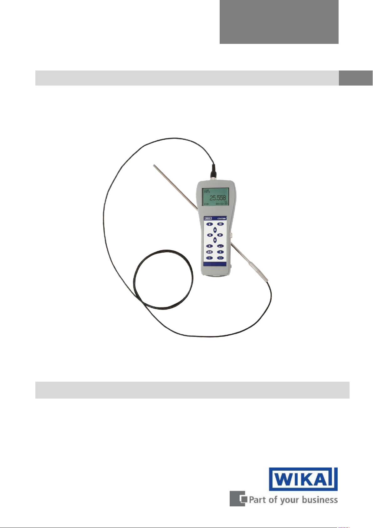
Hand-held thermometer, model CTH7000
GB
Hand-held thermometer, model CTH7000
Operating instructions
Page 2

2 WIKA Operating Instruction, model CTH7000
GB
Hand-held thermometer, model CTH7000
Page
2 - 51
Further languages can be found at www.wika.com.
© 2013 WIKA Alexander Wiegand SE & Co. KG
All rights reserved.
WIKA® is a registered trademark in various countries.
Prior to starting any work, read the operating instructions!
Keep for later use!
Page 3

Contents
WIKA Operating Instruction, model CTH7000 3
EN
14240889 07/2017 EN
1. General Information........................................................................................................... 6
2. Design and function .......................................................................................................... 7
2.1 Overview ............................................................................................................................ 7
2.2 Description ......................................................................................................................... 7
2.3 Scope of delivery ............................................................................................................... 8
3. Safety ................................................................................................................................. 9
3.1 Explanation of symbols .................................................................................................... 9
3.2 Intended use ...................................................................................................................... 9
Application ........................................................................................................................... 9
Functionality ........................................................................................................................ 9
3.3 Improper use .................................................................................................................... 10
3.4 Responsibility of the operator ........................................................................................ 11
3.5 Personnel qualification ................................................................................................... 11
3.6 Personal protective equipment....................................................................................... 11
3.7 Safety marks .................................................................................................................... 12
Symbols ............................................................................................................................ 12
4. Design and Function ....................................................................................................... 13
4.1 Principles of measurement ............................................................................................. 13
4.2 Front panel ................................................................ ....................................................... 14
Overview ........................................................................................................................... 14
Keypad .............................................................................................................................. 15
About the display screen ................................................................................................... 16
CTH7000 thermometer inputs ............................................................................................ 16
Battery Pack ...................................................................................................................... 18
Removing and replacing the battery pack .......................................................................... 18
Battery charger .................................................................................................................. 18
Charging the battery pack ................................................................................. 20
Name plate(s) .................................................................................................................... 21
USB Communication interface connector .......................................................................... 21
4.3 Instrument operating modes .......................................................................................... 21
Measurement Mode ........................................................................................................... 21
Menu Mode ( key) ........................................................................................................... 22
Selecting the thermometer input channel and differential mode (A/B key) .......... 24
Selecting relative temperature measurement (0 key) ......................................... 24
Selecting run/hold mode () ............................................................................. 25
Backlight key () .............................................................................................. 25
Other menu options ........................................................................................................... 25
Selecting Units ................................................................................................ .. 26
Channel options menu (Channel A or Channel B) .............................................. 26
Data logging menu ............................................................................................ 30
Statistics menu ................................................................................................. 32
Settings menu ................................................................................................... 33
Page 4
Contents
4 WIKA Operating Instruction, model CTH7000
EN
14240889 07/2017 EN
System menu .................................................................................................... 35
Setting up Temperature measurement .............................................................................. 38
Temperature measurement with Smart probe (s) ............................................... 38
Instrument calibration ........................................................................................ 38
Firmware Version .............................................................................................. 38
Smart Probe review ........................................................................................................... 39
4.4 Instrument Measurement Range .................................................................................... 40
Instrument measurement working range ............................................................................ 40
Measurement Ranges ................................................................................................ ....... 40
4.5 Smart Probes ................................ ................................................................ ................... 41
About Smart Probes .......................................................................................................... 41
How Smart Probes Work ................................................................................................... 41
Smart Probe Data Security ................................................................................................ 41
Smart Probe Calibration Supervisor ................................................................................... 41
Smart Probe Working Range Monitor ................................................................................ 41
Smart Probe Errors ............................................................................................................ 41
5. Transport, packaging and storage ................................................................ ................. 42
5.1 Transport .......................................................................................................................... 42
5.2 Packaging and storage ................................................................................................... 42
6. Commissioning, operation .............................................................................................. 43
7. Faults ................................................................................................................................ 44
8. Maintenance, cleaning and servicing ............................................................................. 44
8.1 Maintenance ..................................................................................................................... 44
8.2 Recalibration .................................................................................................................... 44
Equipment ......................................................................................................................... 44
9. Dismounting, return and disposal .................................................................................. 45
9.1 Dismounting .................................................................................................................... 45
9.2 Return ............................................................................................................................... 46
9.3 Disposal ........................................................................................................................... 46
10. Specifications .................................................................................................................. 47
10.1 Resistance thermometer measurement ......................................................................... 47
10.2 Display ............................................................................................................................. 47
10.3 Functions ......................................................................................................................... 48
10.4 Supply ................................ .............................................................................................. 48
10.5 Environmental.................................................................................................................. 48
10.6 Dimensions and weight ................................................................................................... 48
10.7 CE conformity .................................................................................................................. 48
11. Communications Interface .............................................................................................. 49
11.1 Introduction ..................................................................................................................... 49
11.2 USB Command syntax .................................................................................................... 49
Command terminators (CR) or (CR)(LF) ............................................................................ 49
Command details ............................................................................................................... 50
SYSTEM:REMOTE ........................................................................................... 50
SYSTEM:LOCAL .............................................................................................. 50
*IDN? ................................................................................................................ 50
MEASURE:CHANNEL? <channel> ................................................................... 50
Page 5

Contents
WIKA Operating Instruction, model CTH7000 5
EN
14240889 07/2017 EN
UNIT:TEMP? <units> ........................................................................................ 51
LOG:DUMP 1 .................................................................................................... 51
LOG:ERASE 1 .................................................................................................. 51
12. Accessories ..................................................................................................................... 51
Declarations of conformity can be found online at www.wika.com.
Page 6

2. Design and function or Short overview
6 WIKA Operating Instruction, model CTH7000
EN
14240889 07/2017 EN
1. General Information
The instrument described in the operating instructions has been designed and manufactured
using state-of-the-art technology. All components are subject to stringent quality and
environmental criteria during production. Our management systems are certified to ISO 9001
and ISO 14001.
These operating instructions contain important information on handling the hand-held
thermometer model CTH7000. Working safely requires that all safety instructions and work
instructions are observed.
Observe the relevant local accident prevention regulations and general safety regulations for the
range of use of the hand-held thermometer CTH7000.
The operating instructions are part of the instrument and must be kept in the immediate vicinity
of the hand-held thermometer model CTH7000 and readily accessible to skilled personnel at
any time.
Skilled personnel must have carefully read and understood the operating instructions, prior to
beginning any work.
The general terms and conditions, contained in the sales documentation, shall apply.
Subject to technical modifications.
Factory calibrations/DKD/DAkkS calibrations are carried out in accordance with international
standards.
Further information:
WIKA Alexander Wiegand SE & Co. KG
- Internet address: www.wika.de / www.wika.com
- Relevant data sheet: CT 55.50
- Application consultant: Tel.: +49 9372 132-0
Fax: +49 9372 132-406
Abbreviations, definitions
Alpha, or ,
is the temperature coefficient, or temperature
sensitivity, of the platinum wire used in PRTs. In
general, the greater the alpha value, the better
the PRT thermometer measurement
reproducibility, stability and performance
PRT
(Platinum Resistance Thermometer)
Pt100
PRT with nominally 100 resistance at 0°C
RTD
Resistance Temperature Device
System accuracy refers to the overall, combined accuracy of the CTH7000 and thermometer.
Page 7
2. Design and function
WIKA Operating Instruction, model CTH7000 7
EN
14240889 07/2017 EN
2. Design and function
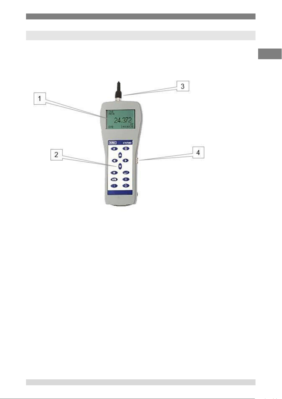
2.1 Overview
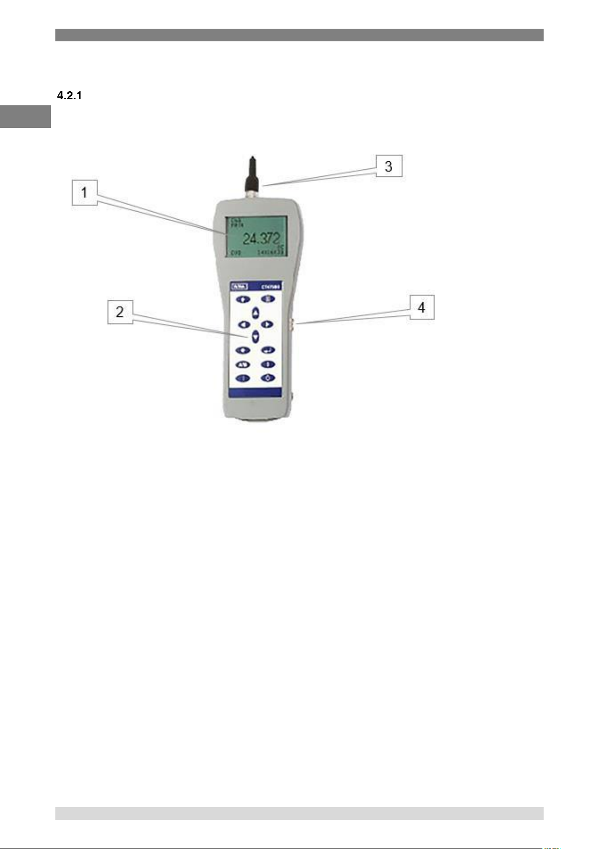
1. LCD display
2. Keypad
3. Inputs at the top
4. USB
2.2 Description
The CTH7000 is a precision instrument designed for laboratory, commercial and industrial
temperature measurement and calibration applications.
Features include:
Two input channels
A large graphic LCD display for excellent viewing of temperature measurement values and
instrument settings
USB communication interface as standard for automated monitoring and calibration
applications
Calibration against traceable external standards
Page 8

2. Design and function or Short overview
8 WIKA Operating Instruction, model CTH7000
EN
14240889 07/2017 EN
The CTH7000 will operate with all 4-wire Pt100 (100 ohm) Platinum Resistance Thermometers
(PRTs) and with virtually all thermistors.
Temperature measurement units are user-selectable and can display C, °F, K and .
Overall system accuracy will depend on the sensor quality and calibration - see the specification
section.
2.3 Scope of delivery
CTH7000 precision thermometer
Battery charger
Operator’s handbook on CD
Calibration certificate
USB lead
Software U-Log
Please contact the Service Team immediately if any of these items are missing or damaged.
Please retain the packaging. In case of return, servicing or calibration, use the original packaging.
Failure to do so may invalidate the warranty and/or incur additional costs outside the warranty
period. Please contact your agent, dealer or supplier when the original packaging is unavailable.
Page 9
3. Safety
WIKA Operating Instruction, model CTH7000 9
EN
14240889 07/2017 EN
3. Safety
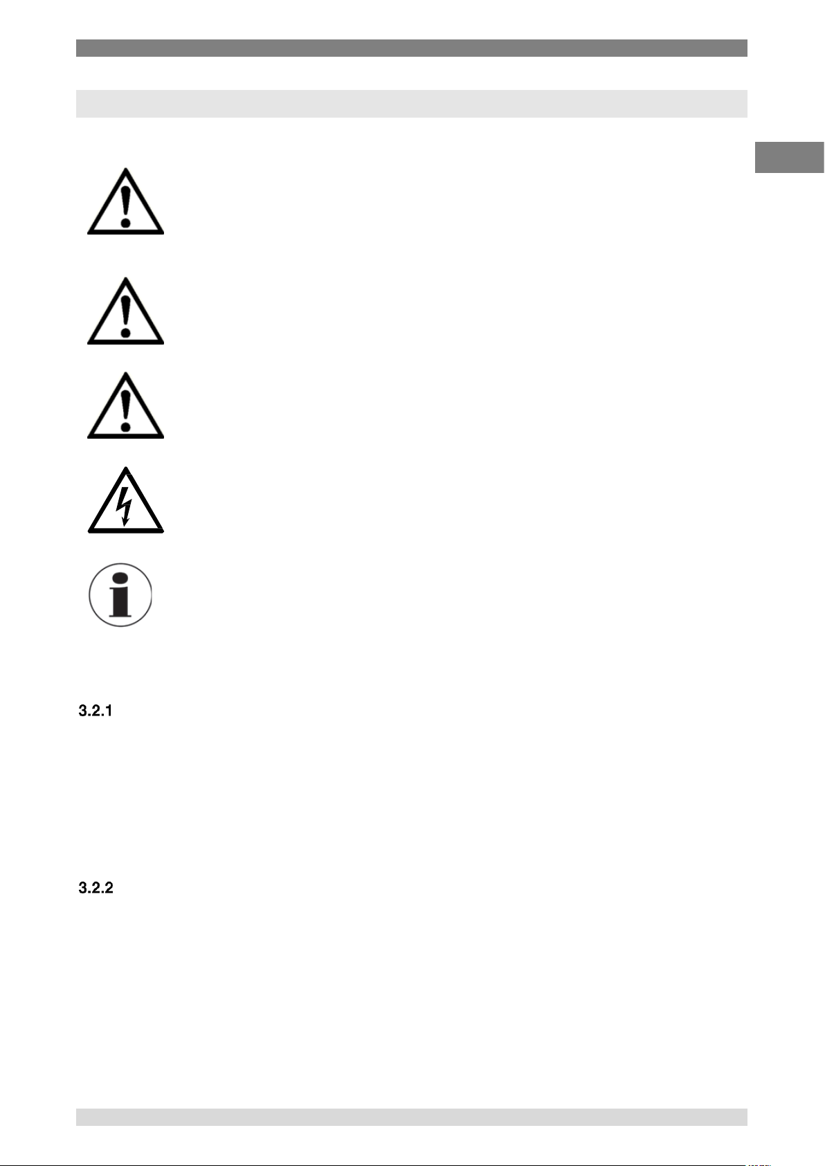
3.1 Explanation of symbols
DANGER!
... indicates a directly dangerous situation resulting in serious injury or
death, if not avoided.
WARNING!
... indicates a potentially dangerous situation that can result in serious injury or
death, if not avoided.
CAUTION!
... indicates a potentially dangerous situation that can result in light injuries or
damage to property or the environment, if not avoided.
DANGER!
... identifies hazards caused by electrical power. Should the safety instructions not
be observed, there is a risk of serious or fatal injury.
Information
... points out useful tips, recommendations and information for efficient and
trouble -free operation.
3.2 Intended use
Application
The model CTH7000 hand-held thermometer is a high performance 2-channel thermometer for
Pt100 and thermistor probes. The hand-held thermometer CTH7000 is a step up in measurement
accuracy with a battery power.
The CTH7000 is designed for laboratory and industrial temperature measurement and calibration
applications intended to be used in a basic electromagnetic environment.
Functionality
The CTH7000 can handle all needs, with accuracies and resolutions normally associated with a
bench top thermometer. Two inputs give direct temperatures from Pt100 or thermistor probes or can
display the temperature difference between them. Measurements can be logged directly to memory
or, use the USB port to control and data log with the PC.
Due to the wide range of this instrument it makes individual instruments needless and makes the
calibration cost-effective.
Page 10

3. Safety
10 WIKA Operating Instruction, model CTH7000
EN
14240889 07/2017 EN
Features included:
■ Simple handling
■ Large display with dual temperature display
■ Min/Max value for monitoring of temperature limits
■ Mean value function for statistical evaluation
■ Selectable channel can be switched off to improve the clarity of the display data
■ Recording and visualisation of temperature cycles with the help of the ULog software
■ Data logger
This instrument is not permitted to be used in hazardous areas!
The instrument has been designed and built solely for the intended use described here, and may
only be used accordingly.
The technical specifications contained in these operating instructions must be observed. Improper
handling or operation of the instrument outside of its technical specifications requires the instrument
to be taken out of service immediately and inspected by an authorised WIKA service engineer.
Handle electronic precision measuring instruments with the required care (protect from humidity,
impacts, strong magnetic fields, static electricity and extreme temperatures, do not insert any
objects into the instrument or its openings). Plugs and sockets must be protected from
contamination.
The manufacturer shall not be liable for claims of any type based on operation contrary to the
intended use.
For indoor use only.
Don't connect lines within a building which are longer than 30 m, or leave the building (including
lines of outdoor installations).
3.3 Improper use
WARNING!
Injuries through improper use
Improper use of the instrument can lead to hazardous situations and injuries.
▶
Refrain from unauthorised modifications to the instrument.
▶ Do not use the instrument within hazardous areas.
▶ Do not use the instrument with abrasive or viscous media.
Any use beyond or different to the intended use is considered as improper use.
Page 11
3. Safety
WIKA Operating Instruction, model CTH7000 11
EN
14240889 07/2017 EN
3.4 Responsibility of the operator
The model CTH7000 hand-held thermometer is a high performance 2-channel thermometer for
Pt100 and thermistor probes.
The operator is therefore responsible for legal obligations regarding safety at work.
The safety instructions within these operating instructions, as well as the safety, accident prevention
and environmental protection regulations for the application area must be maintained.
The operator is obliged to maintain the product label in a legible condition.
To ensure safe working on the instrument, the operating company must ensure
■
that suitable first-aid equipment is available and aid is provided whenever required.
■
that the operating personnel are regularly instructed in all topics regarding work safety, first aid
and environmental protection and know the operating instructions and in particular, the safety
instructions contained therein.
■
that the instrument is suitable for the particular application in accordance with its intended
use.
■
that personal protective equipment is available.
3.5 Personnel qualification
WARNING!
Risk of injury should qualification be insufficient
Improper handling can result in considerable injury and damage to equipment.
▶
The activities described in these operating instructions may only be
carried out by skilled personnel who have the qualifications described
below.
Skilled personnel
Skilled personnel, authorised by the operator, are understood to be personnel who, based on
their technical training, knowledge of measurement and control technology and on their
experience and knowledge of country-specific regulations, current standards and directives,
are capable of carrying out the work described and independently recognising potential
hazards.
Special operating conditions require further appropriate knowledge, e.g. of aggressive media.
3.6 Personal protective equipment
The personal protective equipment is designed to protect the skilled personnel from hazards
that could impair their safety or health during work. When carrying out the various tasks on and
with the instrument, the skilled personnel must wear personal protective equipment.
Follow the instructions displayed in the work area regarding personal protective
equipment!
Page 12
3. Safety
12 WIKA Operating Instruction, model CTH7000
EN
14240889 07/2017 EN
3.7 Safety marks
Symbols
Before mounting and commissioning the instrument, ensure you read the
operating instructions!
CE, Communauté Européenne
Instruments bearing this mark comply with the relevant European directives.
This marking on the instruments indicates that they must not be disposed of in
domestic waste. The disposal is carried out by return to the manufacturer or by the
corresponding municipal authorities (see EU directive 2012/19/EU).
Page 13

4. Design and Function
WIKA Operating Instruction, model CTH7000 13
EN
14240889 07/2017 EN
4. Design and Function
4.1 Principles of measurement
The CTH7000 measures the voltage (Vt) developed across the unknown sensor resistance (Rt) and
the voltage (Vs) across a stable internal reference resistance (Rs). The voltages are proportional to
the resistances so the thermometer resistance is derived from –
s
t
st
V
V
RR
This technique achieves immunity from slow moving time and temperature drifts in the electronics,
as it is not affected by voltage measurement gain variations or current source fluctuations.
In the same way that AC resistance measurement eliminates thermal EMFs, switched DC achieves
a similar advantage. Switched DC works by reversing the current flow on alternate measurement
cycles and taking the average value, thereby cancelling any thermal EMF offsets from the
measurement.
For PRTs, the relationship between resistance and temperature varies slightly from one PRT to
another. Therefore, no matter how accurately the CTH7000 measures the PRT resistance, if the
relationship between resistance and temperature for a particular PRT is not known, accurate
temperature measurement is not possible. For thermistors, the relationship depends totally on the
thermistor type and specifications.
The CTH7000 uses PRT and thermistor calibration data to overcome this problem and calculates
the result from temperature conversion functions stored in either the sensors ‘SMART’ connector or
the CTH7000’s internal non-volatile memory. This method enables the CTH7000 to convert
resistance to temperature, uniquely for each sensor used.
It is very important, therefore, that a sensor without a ‘SMART’ connector is used on a properly
configured input channel and that the probes’ coefficients are correctly entered into the instrument.
System accuracy is a combination of the CTH7000 accuracy in measuring sensor resistance and
the calibration uncertainty placed on PRTs and thermistors by the calibrating laboratory.
Page 14
4. Design and Function
14 WIKA Operating Instruction, model CTH7000
EN
14240889 07/2017 EN
4.2 Front panel
Overview
1. LCD display
2. Keypad
3. Inputs at the top
4. USB
Page 15
4. Design and Function
WIKA Operating Instruction, model CTH7000 15
EN
14240889 07/2017 EN
Keypad
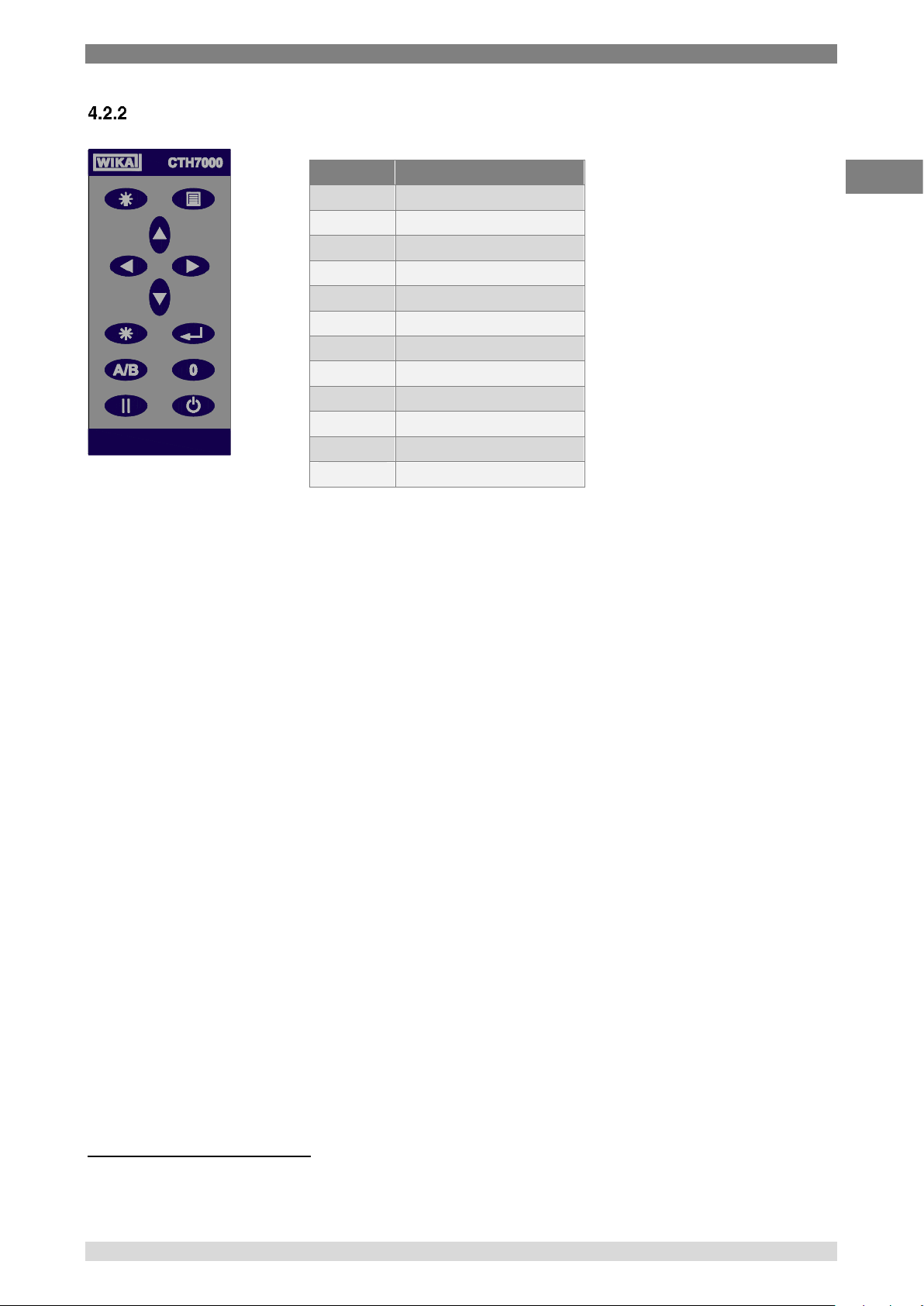
The Power ( ) key turns power on and off1 to the CTH7000.
The CTH7000 uses a menu system. The Menu ( ) key is located at the top right of keypad. Use
the Menu key to access to the less frequently used CTH7000 functions.
The four Arrow ( ) keys are used to navigate through the menus2; the Enter ( ) and
Clear ( ) keys are used to act on the menu selections3.
The Backlight () key located at the top left of the keypad provides LCD illumination when the
ambient light-level is too low for normal viewing.
The A/B key is used to select one of the two channels or the difference (A – B)
The Zero ( 0 ) key is used to provide relative (offset) readings.
The Hold ( ) key is used to freeze the current reading.
1
The CTH7000 may also be set to power-off after a preset period.
2
The Up () and Down () keys can be used to change the displayed units
3
The Clear ( ) key is also used to view CTH7000 statistics; press once to select the statistics page. Press any key to return.
Key
Function
Menu display
Backlight
Up arrow
Down arrow
Left arrow
Right arrow
Clear (view statistics)
Enter
A/B
A/B channel select
0
Zero (offset) reading
Hold reading
Power on/off
Page 16
4. Design and Function
16 WIKA Operating Instruction, model CTH7000
EN
14240889 07/2017 EN
About the display screen
The large graphic LCD screen is the direct link to the instrument, presenting the measurement
results and information or menus to set and control the instrument.
The LCD screen is designed for reflective-viewing under normal ambient lighting; a backlight is
provided for use when ambient conditions are darker.
CTH7000 thermometer inputs
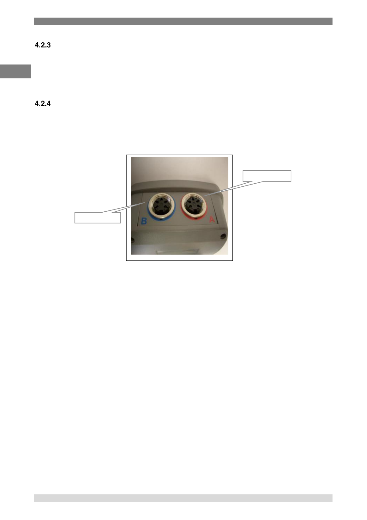
There are two input channels; two 5 pin DIN input-sockets are located at the top of the instrument.
These are designed to take either PRT or thermistor probes. Channel A is colour-coded red.
Channel B is colour-coded blue.
Channel B (blue)
Channel A (red)
Page 17
4. Design and Function
WIKA Operating Instruction, model CTH7000 17
EN
14240889 07/2017 EN
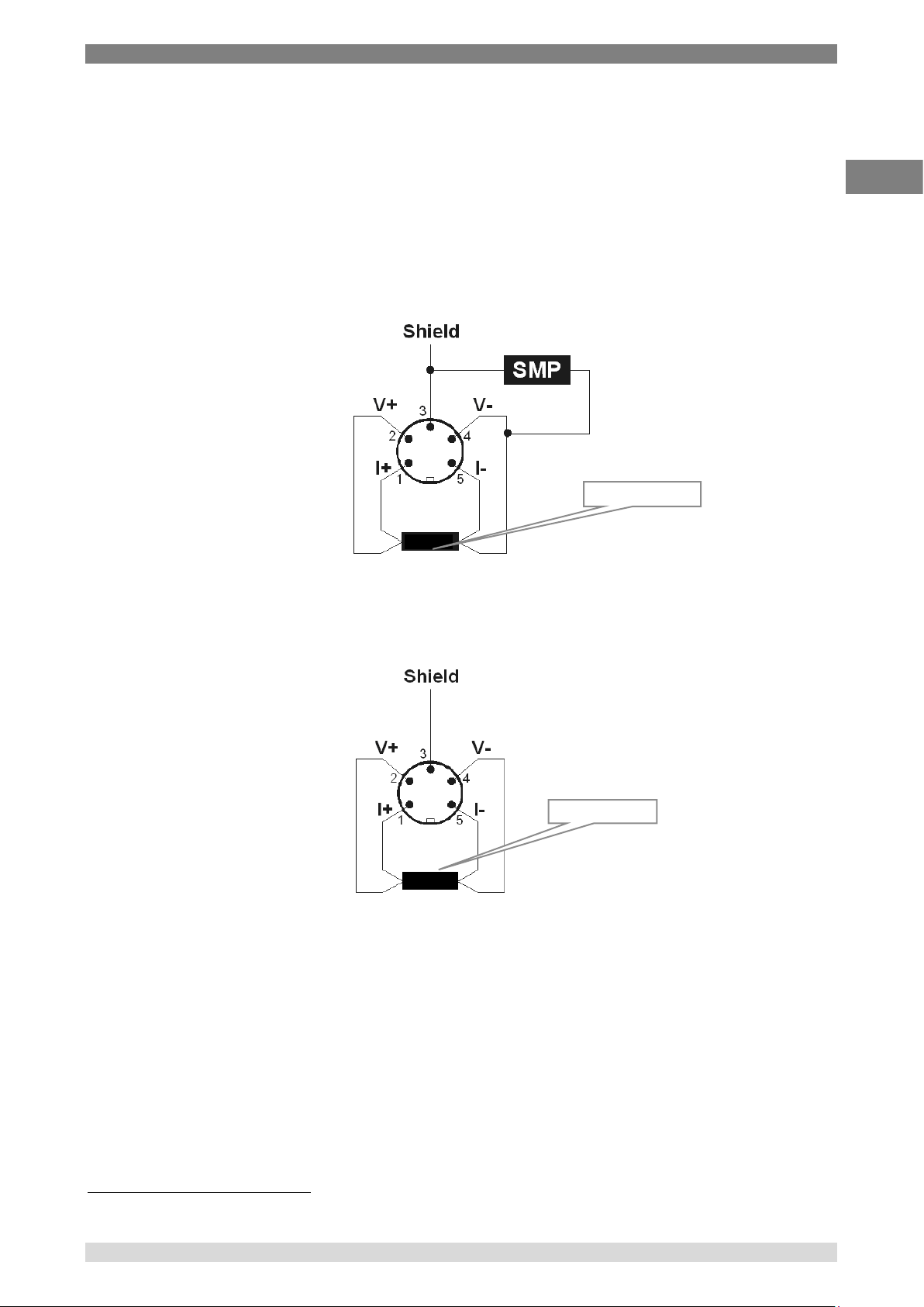
Either channel can accept either Smart or Passive probes; any combination of probes can be use
together. Smart probes (described in section 4.5) contain their own calibration information and
communicate this to the CTH7000 as soon as they are used. Passive probes do not contain
calibration information and the CTH7000 must be set-up with the calibration information for each
probe used (and each time the probe is changed).
Probe connection information for both PRTs and thermistors4 is shown below (viewed looking
towards the sockets) -
4-Wire SMART probe (SMP) PRT/thermistor input
4-Wire Passive probe PRT/thermistor input
4
Two wire PRTs/thermistors must have pins1 & 2 connected together and also pins 4 & 5 connected together.
PRT or thermistor
PRT or thermistor
Page 18

4. Design and Function
18 WIKA Operating Instruction, model CTH7000
EN
14240889 07/2017 EN
Battery Pack
The instrument operates from battery power. The battery pack is replaceable. A low battery
indication is shown on the LCD when the battery needs recharging; the instrument also audibly
indicates a low battery condition. The battery may be d when attached to the instruments.
Removing and replacing the battery pack
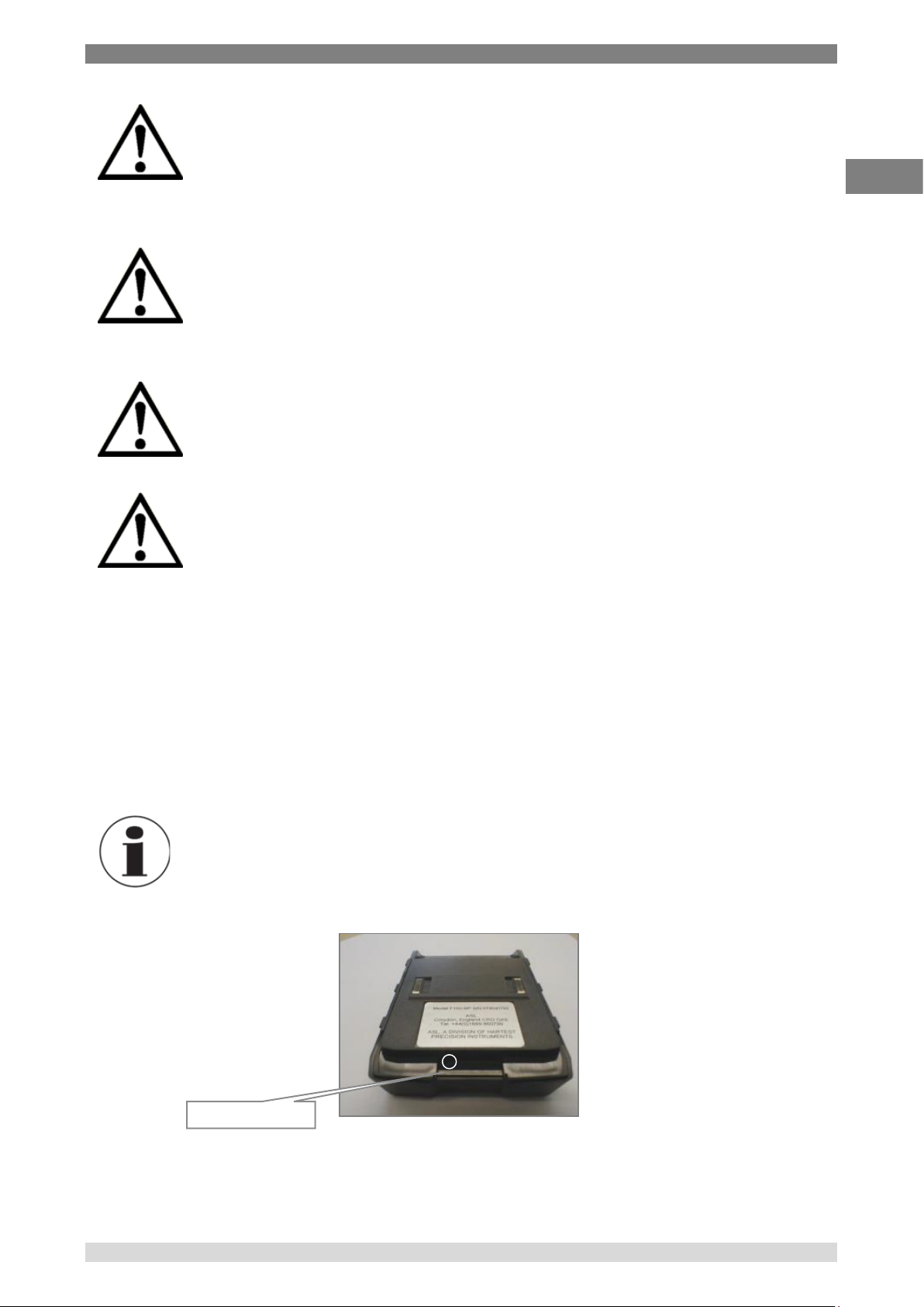
To remove the battery pack, press the latching tab and slide the battery pack backwards.
To replace the battery pack, place the pack in position before sliding home. Check that the battery
pack is securely in position before using the instrument.
Battery charger
Please observe the following warnings (repeated from the front of the manual).
Battery pack removed
Battery charger
input connector
USB
communications
Page 19
4. Design and Function
WIKA Operating Instruction, model CTH7000 19
EN
14240889 07/2017 EN
WARNING!
Only use the battery charger supplied.
Use of any other charger will invalidate the warranty and may lead to the danger of
overheating and to permanent instrument damage.
WARNING!
Take care not to short the battery packs’ contacts with any metal object when the
pack is not connected to the instrument.
WARNING!
Take care not trap any part of your hand when closing the battery compartment.
WARNING!
Never cover the battery pack or charger during use.
The batteries are located in a removable pack located on the base of the instrument.
The battery pack contains two NiMHi cells (in series) and a charger control circuit. The battery pack
must only be charged using the unit supplied.
The battery pack has a socket on its side that accepts the charger’s connector. A LED (viewable
through an aperture on the top-rear of the pack) indicates the charger status.
The battery charger is provided with various interchangeable mains connectors; select the one that
you require - see the charger PSU pack for details.
Information
Disconnect the charger when not charging the battery pack.
Charge indication LED
Page 20
4. Design and Function
20 WIKA Operating Instruction, model CTH7000
EN
14240889 07/2017 EN
Charging the battery pack
The CTH7000 battery pack may be charged during instrument use, when the instrument is off, or
when the pack is detached from the CTH7000.
Information
Performance may degrade if the batteries are charged during use.
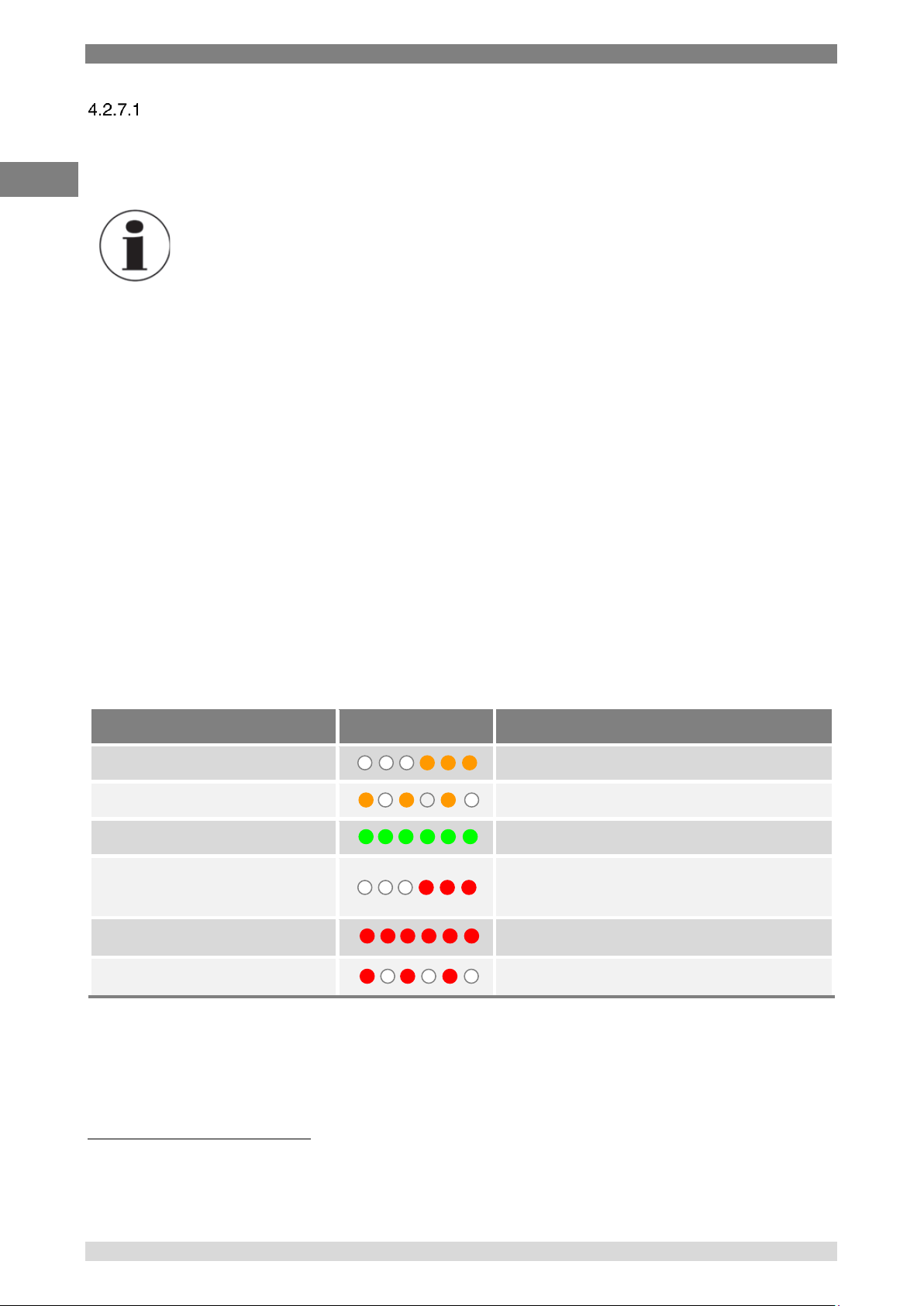
Please follow the instructions below to ensure that the battery pack is fully charged (LED
charge status is shown in the table below) –
Turn off power to the adapter before plugging it into the side of the battery pack.
Switch on the power adapter (6 Vdc), ensuring the LED flashes orange.
Leave the battery pack to fully charge. An overnight charge of about 10 hours (for a
flat battery with the CTH7000 off5) will ensure that the pack is fully charged (the
actual time depends on the initial battery state)6. Charge time will increase if the
CTH7000 is used during this period.
Turn off and remove the power adapter after charging is complete.
The meaning of the various LED indications is shown on below –
Status LED
LED indication
LED indication
Slow orange flash (1 s)
Trickle charge
Fast orange flash (0.2 s)
Fast charge
Solid green
Charged (trickle charge enabled)
Slow red flash (1 s)
Low battery temperature (trickle charge
enabled)
Solid red
PSU voltage too high7
Fast red flash (0.2 s)
Hardware error8
5
Allow 5 minutes before use if the batteries are completely flat.
6
Charge times may increase at higher ambient temperatures.
7
Charge times may increase at higher ambient temperatures.
8
Refer to customer services.
Page 21
4. Design and Function
WIKA Operating Instruction, model CTH7000 21
EN
14240889 07/2017 EN
Name plate(s)
The instrument rating plate shows the instruments maximum power consumption and instrument
serial number.
The label on the battery charger shows its operating voltage, current, frequency and pack’s serial
number.
USB Communication interface connector
The USB connector is fitted as standard. Communication requires the installation of the USB driver
on a PC. See the separate information supplied on the CD. A standard USB cable is supplied with
the CTH7000.
The instrument can be used with the ULOG program (supplied on the CD) or simply used to transmit
ASCII data, which may be recorded using a simple terminal program.
Information
Communication via an USB cable connected to a PC may cause the
CTH7000 to be noisy. WIKA can accept no responsibility for any
performance degradation when connected to a PC.
4.3 Instrument operating modes
The instrument has two operating modes -
Measurement Mode which displays the measurement readings and status
information
Menu Mode which lets you select and alter the instrument operation and its settings
Measurement Mode
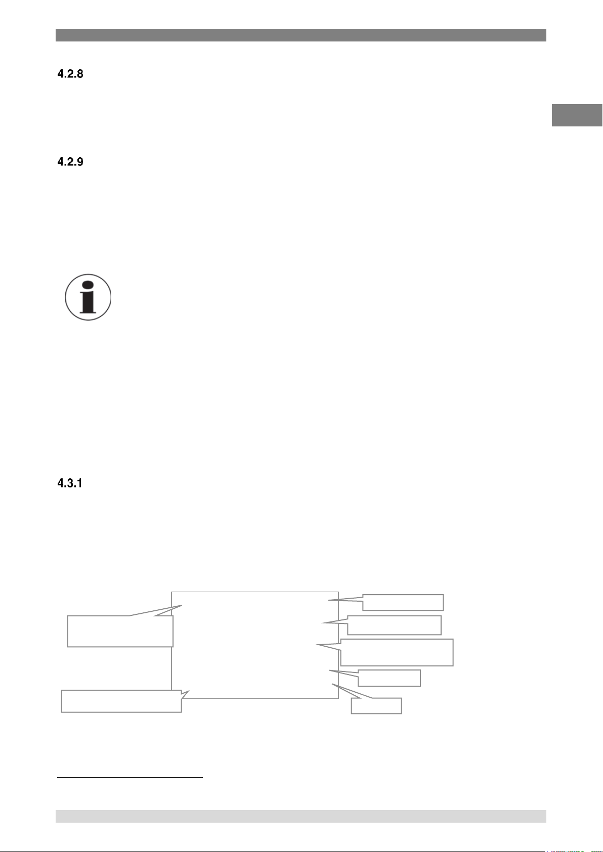
In Measurement Mode, the LCD displays the current reading (temperature or resistance), the unit
symbol, the channel and type of sensor selected (and conversion method); the time of day is also
shown9. This is the normal operating display for the CTH7000. The display will look similar to the one
shown below -
9
The time will be replaced by ‘Logging’ or ‘Remote’ when these modes are selected
ChA s:CT H70 00- 123 4
PRT4
Ba t
22.479
oC
ITS-90 10:24:33
Smart probe serial
Current reading with units
displayed below
Time of day
Reading units
Low battery indication
Channel (ChA) using a 4
wire sensor (PRT4)
Probe conversion method
Page 22
4. Design and Function
22 WIKA Operating Instruction, model CTH7000
EN
14240889 07/2017 EN
This display will always reflect the operation of the instrument, showing the current reading and
settings. Readings are updated at the normal conversion rate of one every two seconds.
Menu Mode ( key)
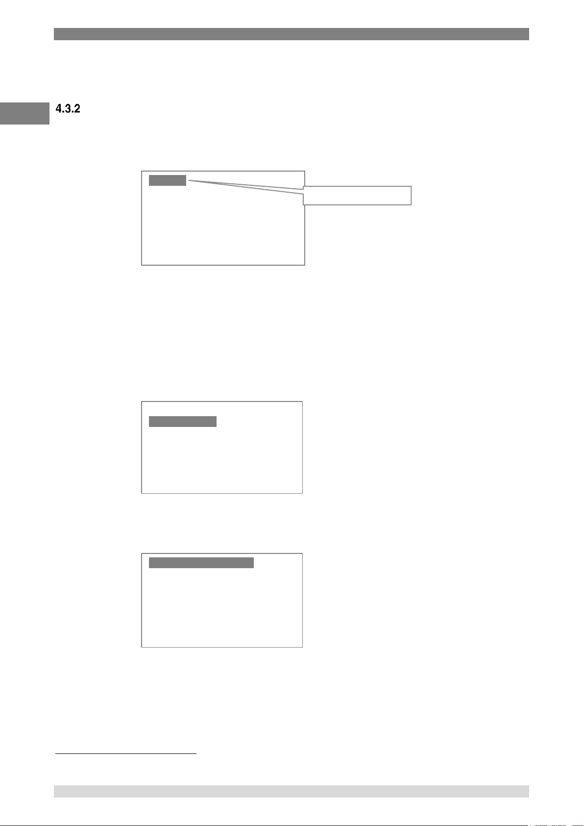
In menu mode, the LCD displays the various options available to control CTH7000 operation.
Press the Menu key ( ) to select the menu screen.
The reverse-video background indicates the menu that will be selected should the Enter key ( )
be pressed (Units selection in the example above). Further menu options will follow once the Enter
key has been pressed.
Press the Up ( ) and Down ( ) keys to move through the options. Pressing an up/down key will
move the reverse video selection one line up or down one line10. Once the selection is corrrect,
press the Enter key. So, for example, to change channel A options, press the Down key ( ) once
to obtain the following display -
Now press the Enter key ( ) to select this option. The following screen will appear (when a Smart
probe is connected to channel A). The display will be different for a passive probe –
10
The selection line will wrap round from top to bottom (or bottom to top) on repeated arrow presses.
Unit s
Chan nel A
Chan nel B
Logg ing
Stat ist ics
Sett ing s
Syst em
Current menu highlighted
Unit s
Chan nel A
Chan nel B
Logg ing
Stat ist ics
Sett ing s
Syst em
SMP Pro be Inf o
SMP Coe ffi cie nts
Page 23

4. Design and Function
WIKA Operating Instruction, model CTH7000 23
EN
14240889 07/2017 EN
Press the Down key ( ) once to obtain –
Now that this menu has been highlighted, press the Enter key ( ) once to obtain –
In this example, pressing the Up or Down key will display more of the Smart probes’ coefficients.
Pressing the Clear key ( ) will return the display to the previous menu. Press the Clear key ( )
once more to return to Measurement mode. Pressing the Enter key ( ) will return the CTH7000
immediately to Measurement Mode (generally applies to all lower level menu options).
No changes can be made in this example. When changes are made, all settings are stored and
retained when power is removed.
Refer to the sections on Smart Probes for more details.
SMP Pr obe In fo
SMP Coe ffi cie nts
C hA( s) C VD
R0 +1 .00 000 e+0 2
A +3 .90 830 e- 03
B - 5.7 750 0e- 03
Read On ly
Up/D own M ove
Clea r Exi t
Page 24
4. Design and Function
24 WIKA Operating Instruction, model CTH7000
EN
14240889 07/2017 EN
Selecting the thermometer input channel and differential mode (A/B key)
The channel Select key ( A/B ) is used to change between channels and also to select the
differential mode ( A – B ). The channel selection order is –
Channel A Channel B Channel (A – B) Channel A
A missing probe will be indicated on the display by a series of dashed lines.
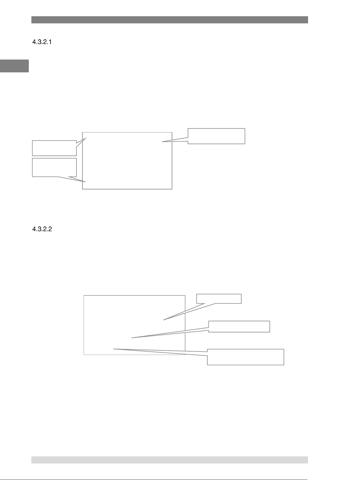
In differential mode (when both channel A and channel B have probes connected), the screen will
look similar to the following example. The asterisk next to the ChA and ChB legends will alternate as
readings are updated.
The probe conversion indicator (bottom-left) displays the conversion method for the current reading
(and so will alternate if the two channels have different conversion methods).
Selecting relative temperature measurement (0 key)
The instrument displays a reading value relative to a fixed offset in Zero (or relative) mode. Press the
Zero ( 0 ) key to select this mode.
In Zero mode, the instrument stores the last reading (at the time of Zero key press) to subtract from
all subsequent readings. It continues doing this until it is either cancelled by pressing the Zero key
again or until power is removed.
Zero mode may be used on differential measurements (A – B). In this case, the difference is set to
zero at the time the key is pressed and the absolute value in the example above, is replaced by the
absolute difference value.
To cancel the relative measurement mode, press the Zero ( 0 ) key again. Zero mode is cancelled
when power is turned off.
ChA * 2 2.0 48
-ChB 2 2.0 90
-0.042
oC
CVD 11: 53: 08
Probe conversion
for current channel
Individual channels
readings
Differential mode
indicator
ChA s:CT H70 00- 123 4
PRT4
0.009
( 022.048)
oC
Offset 10:24:33
Zero offset value
Absolute value (flashing)
Zero mode indication alternates
with the conversion method
Page 25
4. Design and Function
WIKA Operating Instruction, model CTH7000 25
EN
14240889 07/2017 EN
Selecting run/hold mode (
)
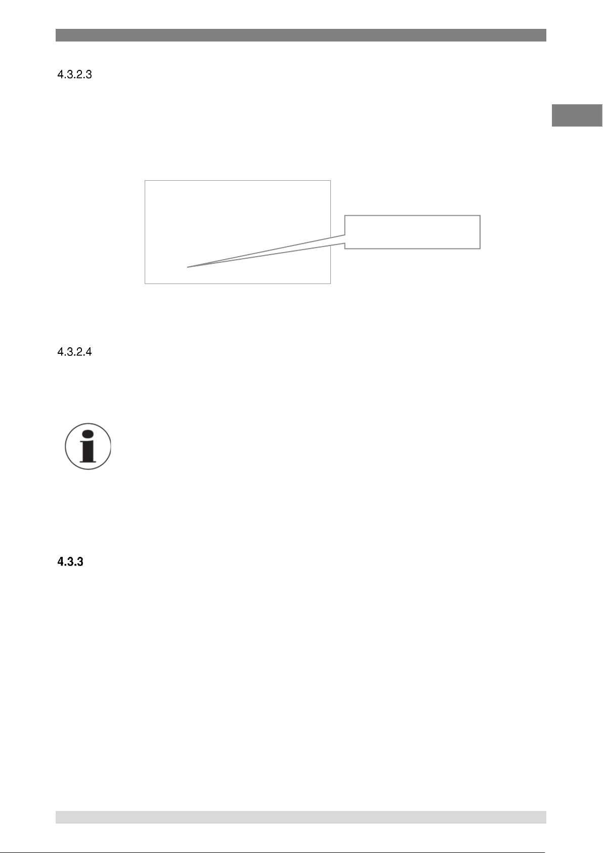
Instrument measurements stop completely when Hold mode is active. This is indicated on the
bottom-left of the display where Hold mode indication alternates with the current conversion
method, providing a flashing indication. Hold mode may be used when the CTH7000 is in differential
mode.
Press the Hold () key to alternate between run and hold modes. Hold mode is cancelled when
power is turned off.
Backlight key (
)
Press the Backlight key () to illuminate the display. Once on, the backlight will go automatically off
after about 10 seconds; alternatively, press the key again to turn it off.
Information
When the CTH7000 is battery operated, using the backlight will dramatically
reduce battery life (by about 30% if used continually at full-brightness).
The brightness level can be set on the Settings menu (see later section). Reducing the
brightness value will increase battery life when the backlight is used.
Other menu options
This section describes the other options available through menu selection. Generally, these options
are set once and then altered rarely. The set-up is stored in non-volatile memory and recalled when
power is reapplied.
In the following sections, the top level menu is shown, followed by the sub-menu(s) that it selects.
ChA s:CT H70 00- 123 4
PRT4
22.479
oC
Hold 10:24:33
Hold mode indication alternates
with the conversion method
Page 26
4. Design and Function
26 WIKA Operating Instruction, model CTH7000
EN
14240889 07/2017 EN
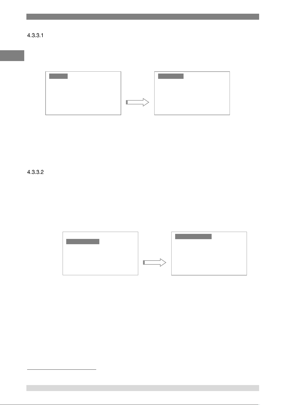
Selecting Units
11
Press the Menu key ( ) to change the measurement units. The Units menu will be highlighted.
Press the Enter key once to reach the Units selection menu.
Select the units required with the Up/Down keys and then press the Enter key. Units of Celsius
(°C), Fahrenheit (°F), Kelvin (K) or Resistance () can be selected; the current units are shown on
the Measurement Menu screen. Changing units will automatically clear any statistics. The current
measurement units are retained when power is removed.
Having selected the new units, press the Menu key to return to Measurement Mode.
Channel options menu (Channel A or Channel B)
Operation of channel A and channel B is identical; Press the Enter key to select the sub-menu –
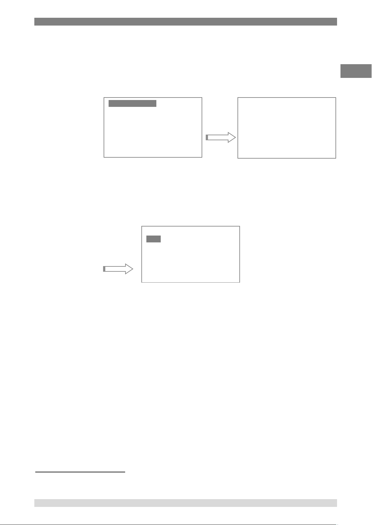
a) Probe type
The sub-menu is used to select the type of probe attached. There are two completely
different probe types - either PRT or Thermistor. This probe selection sub-menu is
used to set these options.
The currently selected sensor type is always shown at the top left of the
measurement screen (see the example shown in section 4.3.1).
Channel A is always used for the PRT probe and channel B is always used for the
Thermistor probe.
11
Alternatively, the Up () and Down () keys can be used to change the displayed units
Unit s
Chan nel A
Chan nel B
Logg ing
Stat ist ics
Sett ing s
Syst em
Celc ius
Fahr enh eit
Kelv in
Ohms
Unit s
Chan nel A
Chan nel B
Logg ing
Stat ist ics
Sett ing s
Syst em
Prob e T ype
Temp Co nv
Coef fic ien ts
Page 27
4. Design and Function
WIKA Operating Instruction, model CTH7000 27
EN
14240889 07/2017 EN
Use the Down key (twice) to select the thermistor probe on channel B. When the
menu is entered again, the thermistor line will be highlighted.
Selection of PRTs is more involved since the conversion method has to be set at the
same time as the probe is changed. Selecting one of the PRT menus will display the
passcode screen –
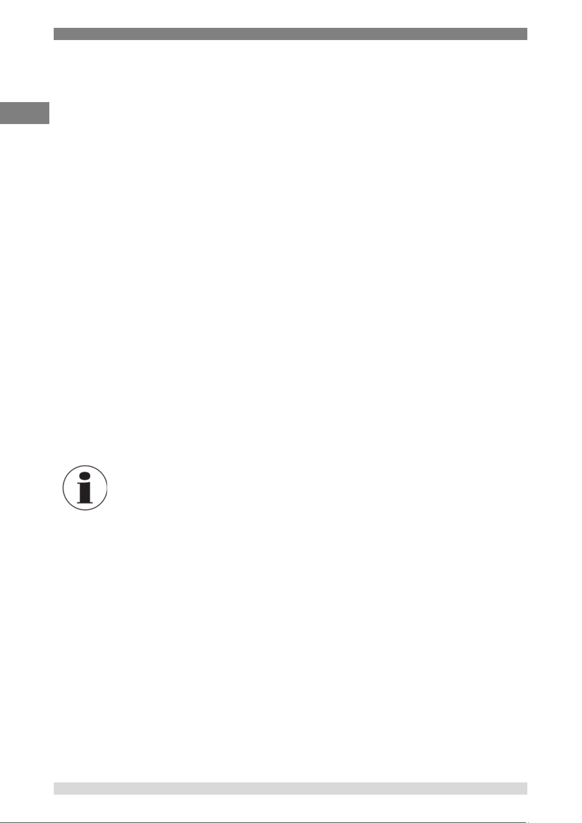
b) Conversion method
Use the Up/Down arrow keys to increment or decrement the passcode. Use the
Enter key once the correct passcode has been set; this procedure helps to prevent
inadvertent changes. The default passcode setting12 is 4300.
This screen will only appear once the correct passcode has been entered. This
screen shows that the CVD conversion method is currently selected. Use the Up and
Down keys to highlight the required conversion method and then use the Enter key
to select it.
12
This can be changed using the Settings menu; keep careful note of the new value if changed. A lost password can be retrieved, but
llllllyou will need to contact WIKA directly for further information.
PRT 4 w ire
NTC Th erm istor
DIN
CVD
ITS - 90
Passc ode = 000 0
Left /Rt se lec ts
Up/D own ch ang es
Ente r OK
Page 28
4. Design and Function
28 WIKA Operating Instruction, model CTH7000
EN
14240889 07/2017 EN
For PRTs, the instrument provides three standard algorithms for converting
resistance to temperature. The choice of algorithm will depend on the type of PRT
and its calibration –
DIN (1992) - used for un-calibrated industrial PRTs with 0.00385 ‘alpha’
value, to provide a conversion of resistance to temperature in
accordance with BS EN60751 (ITS 90) standard
CVD coefficients - Callendar van Dusen used for calibrated industrial or
low alpha PRT’s of 0.00385
ITS-90 coefficients - used for calibrated high alpha PRT’s of values
0.003926 to 0.003928
The choice of conversion method and the relevant coefficients are set from this
menu.
For Thermistors, the instrument provides one standard algorithm for converting
resistance to temperature –
Steinhart and Hart
c) Probe coefficients
Both PRT and Thermistor probes must be correctly calibrated to produce their most
accurate performance. The CTH7000 can store calibration data for each of the two
channels; this information is only required when passive probes are being used.
When Smart probes are used, the calibration data is stored in the probe and the
coefficients held in the CTH7000 are not required or used.
Information
Smart probes use their own internal calibration data. The instrument
coefficients are ignored when a Smart probe is attached.
When passive probes are used, correct entry of the parameter values is absolutely
critical to obtain accurate readings. For this reason, the coefficients menu is
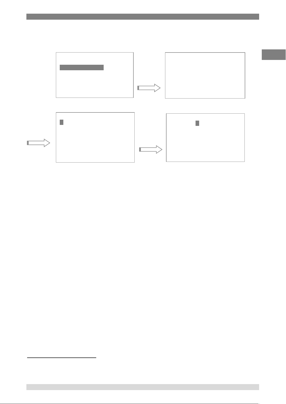
passcode protected. The passcode screen (below) will appear once the Coefficients
menu has been selected. Use the Up and Down arrow keys to increment or
decrement the passcode value.
Page 29
4. Design and Function
WIKA Operating Instruction, model CTH7000 29
EN
14240889 07/2017 EN
Use the Enter key once the correct passcode has been set; this procedure
helps to prevent inadvertent changes. The default passcode setting13 is 4300.
The coefficient edit screen will appear once the correct passcode has been entered.
In this example, the edit screen for CVD coefficients is shown; the first digit of the R0
coefficient will be highlighted (in this case the ‘1’). This is the current cursor position.
Use the Up and Down keys to change the value under the cursor. Once this value
is correct, use the Left and Right keys to select the next digit to set.
Use the Enter key once the complete coefficient has been edited correctly;
alternatively use the Clear key to move on to the next coefficient14. The coefficients
will be set to the value shown when the Enter key is pressed.
Once the first coefficient has been edited, the screen will scroll (if more than three
coefficients are required). Note that DIN coefficients cannot be edited.
Follow a similar procedure for entry of NTC thermistor coefficients.
13
This can be changed using the Settings menu; keep careful note of the new value if changed. A lost password can be retrieved, but
llllllyou will need to contact WIKA directly for further information.
14
Use the Clear key repeatedly to exit without changing any of the coefficients.
Prob e T ype
Temp Co nv
Coef fic ien ts
Passc ode = 000 0
Left /Rt se lec ts
Up/D own ch ang es
Ente r OK
CHA IT S90
Rtp
+1. 000 00e +02
A +3.90 830 e-03
B -5 .77500e- 07
Up/D own mov e
Ente r edi t
Clea r ex it
EDI T
Rtp +
1.0 000 0e+ 02
A +3. 90 830 e-03
B -5 .77500e- 07
Left /Rt s ele cts
Ente r c han ges
Clea r sa ves
Page 30
4. Design and Function
30 WIKA Operating Instruction, model CTH7000
EN
14240889 07/2017 EN
Data logging menu
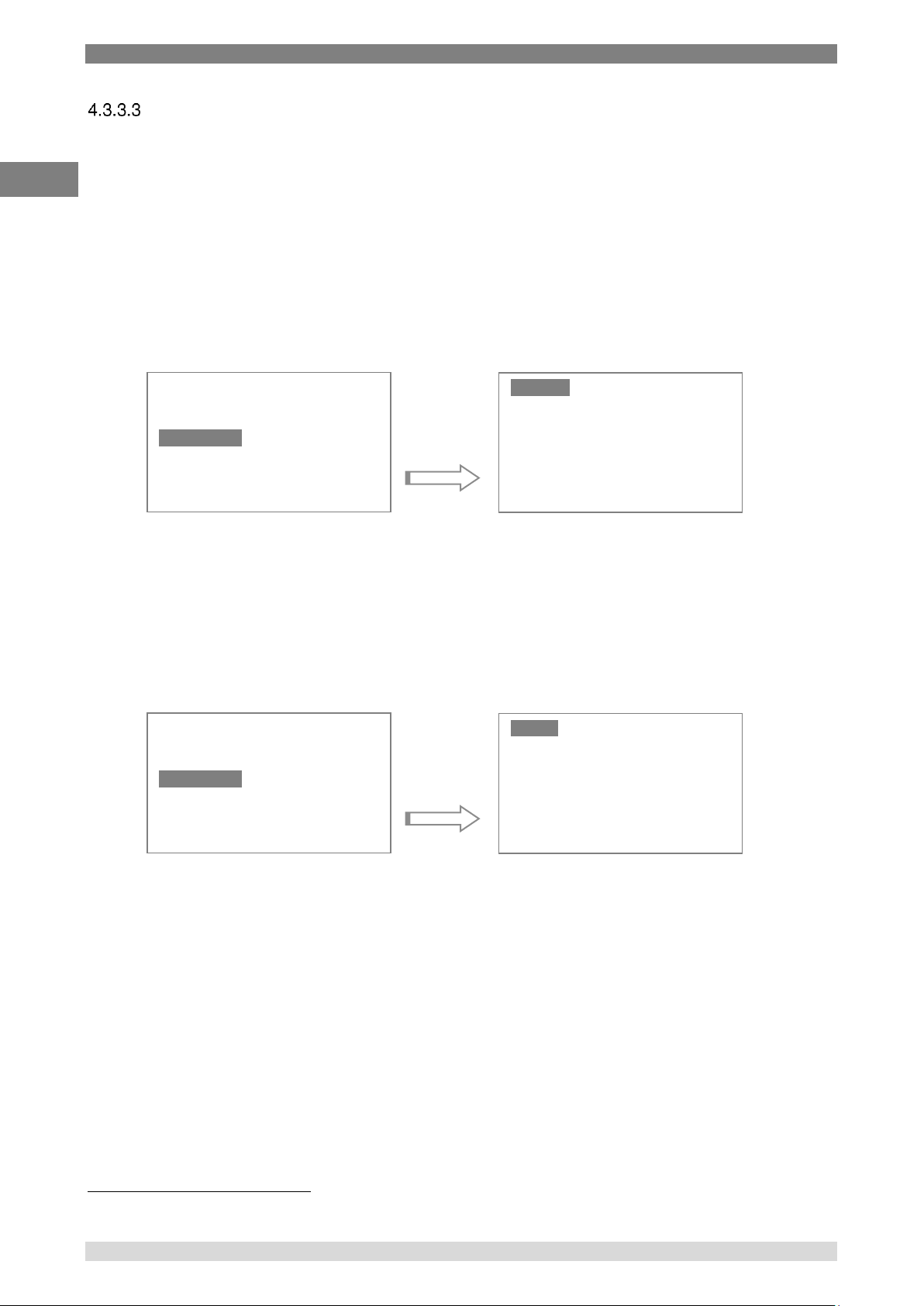
The CTH7000 can log data. Logging status is always shown at the bottom right-hand of the
measurement screen.
Data can be logged at regular intervals (the interval is set when Setup selected), reviewed and
logging can be turned on and off.
Press the Enter key to select the sub-menu used to set the various logging options.
Note that there are a finite number of data points that can be stored, so eventually, any old
results will be overwritten as the selected log will eventually wrap-round – i.e. the oldest
reading will be overwritten first15.
Use the Start menu item to begin logging.
Select Clear to clear the log and return to the main menu.
Selecting Stop (see below) will halt logging. Logging can be restarted using the Start menu item
(logging will then continue after the last point previously logged).
Only two menu options will be available when the instrument is logging.
15
After approximately 8000 points when continuously logging; starting and stopping the log will decrease this number points available.
Logg ing
Chan nel A
Chan nel B
Logg ing
Stat ist ics
Sett ing s
Syst em
Star t
Setu p
Revi ew
Clea r
Logg ing
Chan nel A
Chan nel B
Logg ing
Stat ist ics
Sett ing s
Syst em
Stop
Revi ew
Page 31
4. Design and Function
WIKA Operating Instruction, model CTH7000 31
EN
14240889 07/2017 EN
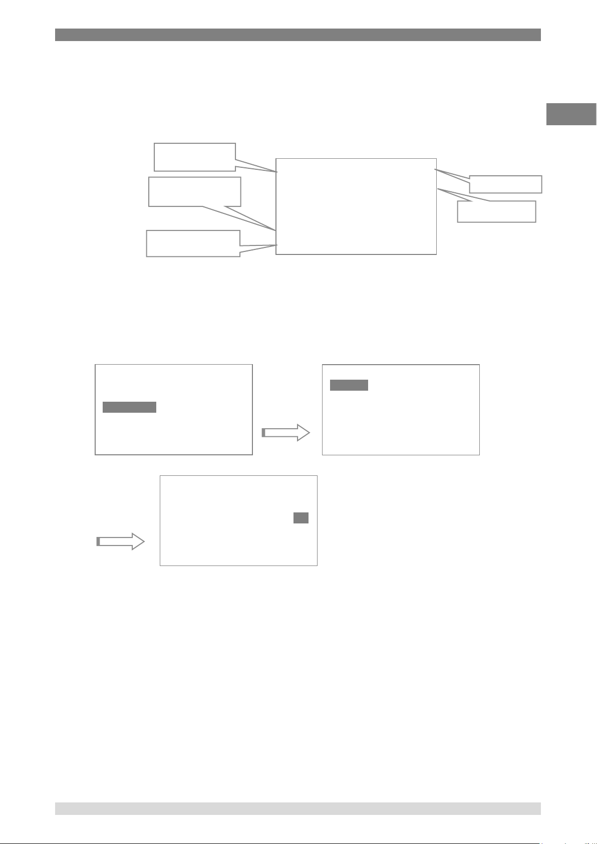
a) Review
Results similar to the following example will appear once the Review key has been
pressed.; exact details will vary with the instrument setup. The example shows
channel A results logged at 2 second intervals.
Use the Down key to scroll through the logged readings a page at a time.
Press the Clear key ( ) to return to the main menu screen.
b) Setup
Use the setup menu to set the logging interval. Either select the required interval with
the Enter key or use the Clear key to return to the measurement menu.
The interval can be set anywhere between 1 second and 59 minutes 59 seconds (a
logging interval of 2 seconds is shown in the example). Selecting an interval of 00:00
will log data as fast as possible; select an interval that best matches your
requirements. Logging with a larger data intervals effectively increases the total
period for which data can be logged.
Logging will stop when the power is turned off.
10 – 1 8 A pri l 0
22:27 A 12 0.0 00F
22:29 A 1 20. 000F
22:3 1 A 1 20. 000F
22:3 3 A 1 20. 000F
22:3 5 A 120 .00 0F
22:3 7 A 1 20. 000F
Dn Nex t P g
Use the down key to
select the next page
Hour of reading &
date readings
Reading and units
Minutes/seconds and
channel
Logg ing
Chan nel A
Chan nel B
Logg ing
Stat ist ics
Sett ing s
Syst em
Star t
Setu p
Revi ew
Clea r
Current page
Hist ory Se tup
MM :SS
Intv l: 00: 00: 02
Page 32
4. Design and Function
32 WIKA Operating Instruction, model CTH7000
EN
14240889 07/2017 EN
Statistics menu
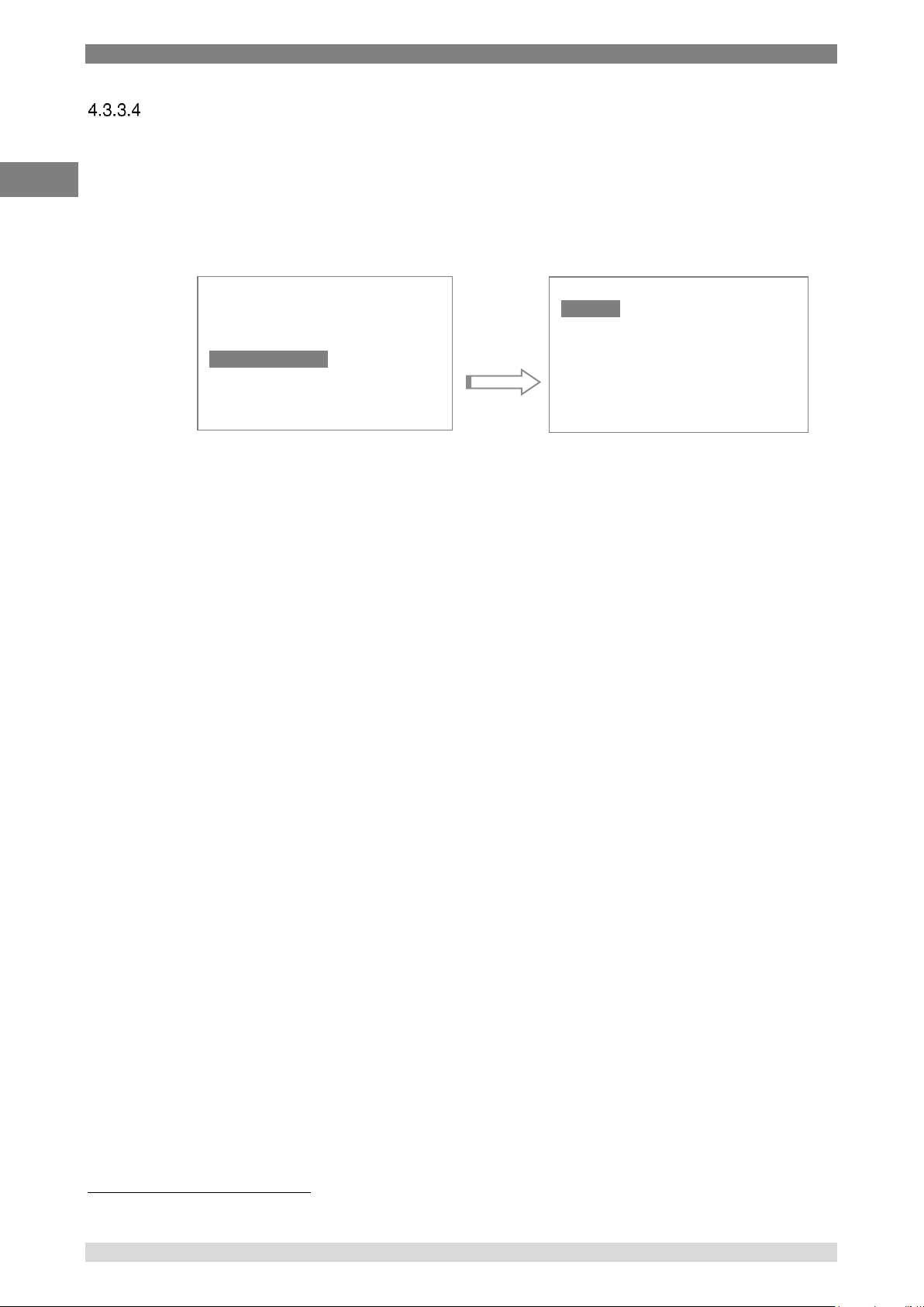
The CTH7000 provides statistics on the data it is collecting. Press the Enter key to select the
statistics sub-menu.
Statistical information is calculated continuously from the moment statistics are cleared (see
sub-menu). Changing any parameter that affects the calculation (e.g. units) will automatically
clear and restart calculation.
The Exit option is used to return to the Measurement Menu after viewing statistics.
Alternatively, press the Clear key ( ) to return to Measurement Menu without clearing
statistics.
The minimum, maximum, mean, standard deviation and total number of readings are
displayed on this screen16. Select Clear to immediately clear and restart the statistical
calculations.
16
The maximum and minimum values are also displayed continuously on the measurement menu screen.
Unit s
Chan nel A
Chan nel B
Logg ing
Stat ist ics
Sett ing s
Syst em
Exit
Clea r
ChA
Mn 23 .45 6
Mx 2 3.5 59
Mean 23. 405
Std dev 0 .010
Tota l 10
Page 33
4. Design and Function
WIKA Operating Instruction, model CTH7000 33
EN
14240889 07/2017 EN
Settings menu
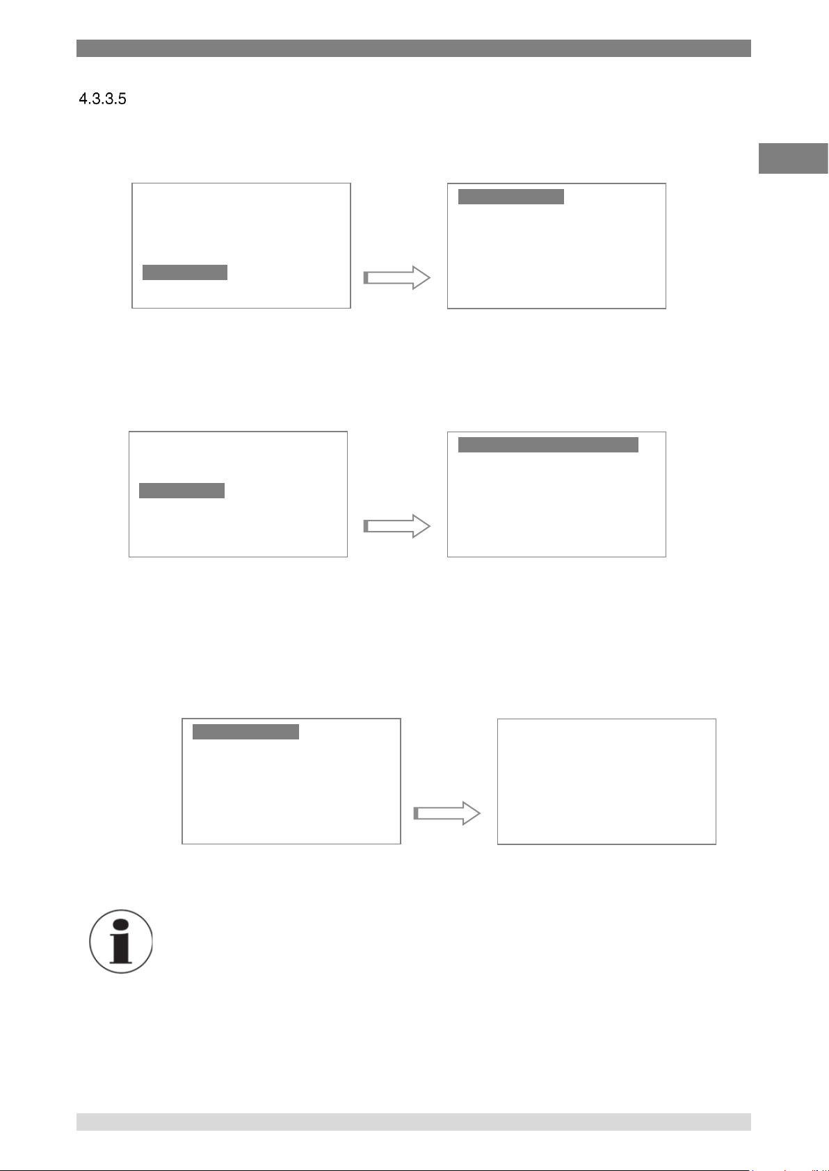
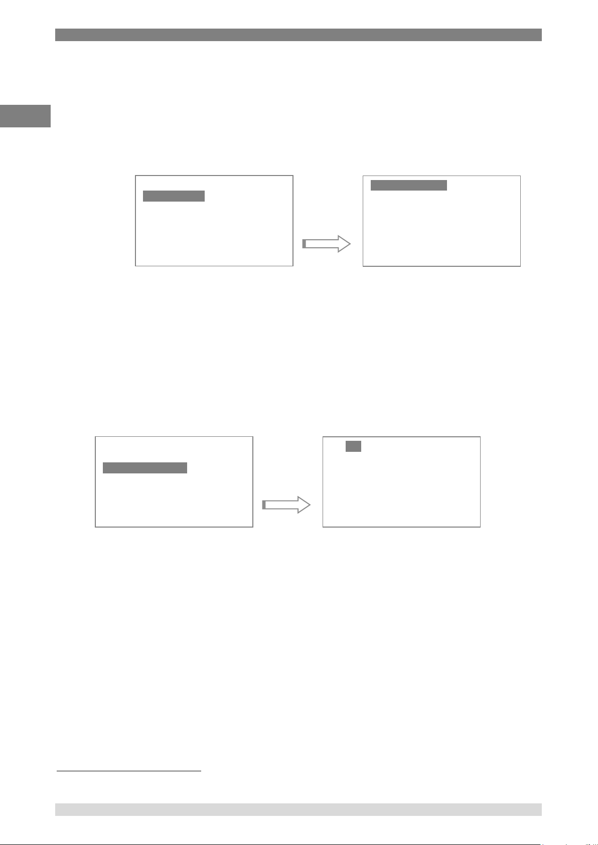
Several operational parameters can be changed in the Settings menu. Press the Enter key to select
the Settings sub-menu. For example, to change the ADC mode (50/60 Hz) setting -
CTH7000 has been set to 50 Hz & 60 Hz reject (rejection filter) by default. Select 50 Hz or 60 Hz,
depending on the operational mains frequency in your area. This can provide better noise rejection.
See the menu screen shown below.
a) Brightness
Selecting this option allows the brightness of the LCD backlight to be adjusted. Use
the Enter key once you are happy with the backlight intensity. Use the Clear key to
exit without altering the set value.
Information
When the CTH7000 is battery operated, using the backlight will dramatically
reduce battery life. The current used increases as the backlight intensity
rises.
Unit s
Chan nel A
Chan nel B
Logg ing
Stat ist ics
Sett ing s
Syst em
Brig htn ess
Time out s
Time & Dat e
ADC Mod e
Brig htn ess
Time out s
Time & Dat e
ADC Mod e
50 & 60 Hz Re jec t
50 H z R eject
60 H z R eject
Brig htn ess
Time out s
Time & Dat e
ADC Mod e
Set Bright nes s
Use Up/ Dow n K ey s
Any key to Ex it
49
Page 34
4. Design and Function
34 WIKA Operating Instruction, model CTH7000
EN
14240889 07/2017 EN
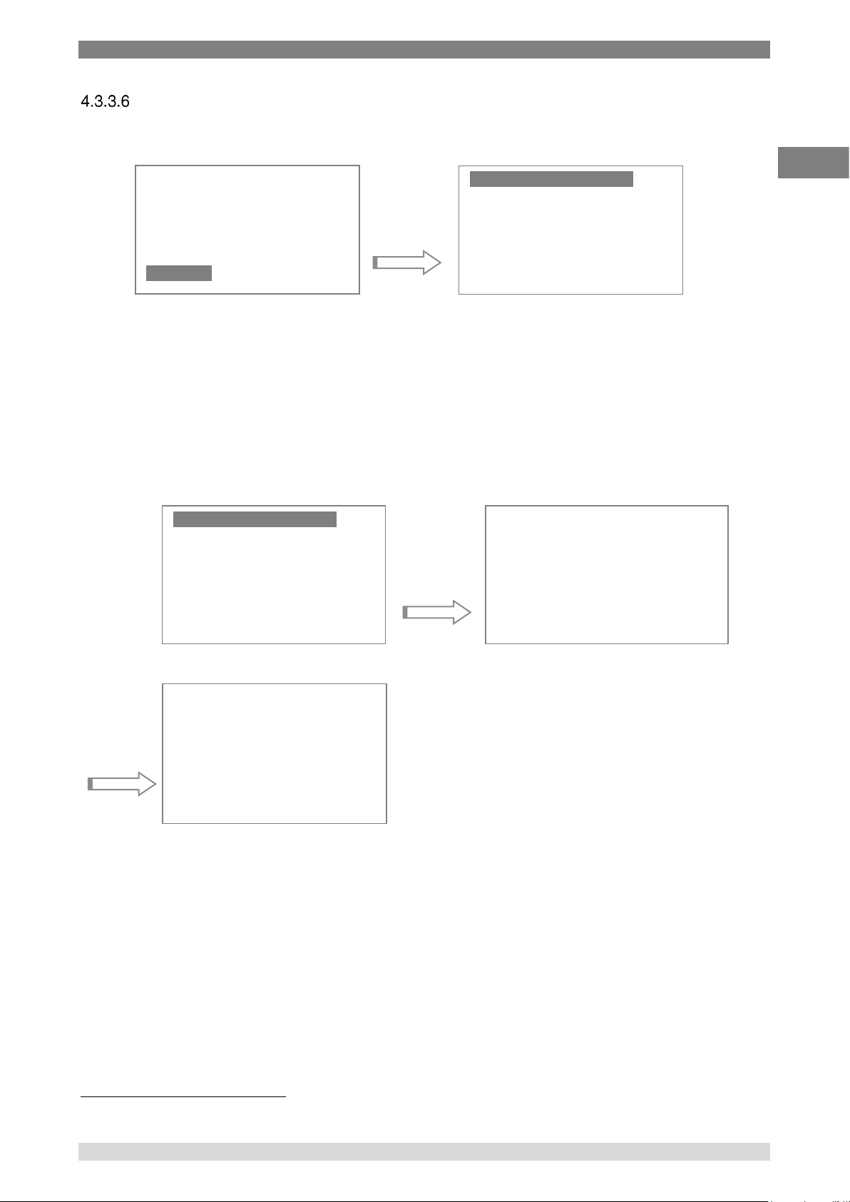
b) Timeouts
The CTH7000 can be set to timeout after a preset period (to save battery life); by default the
timeout is off.
Selecting this option allows the various timeout values to be set. Use the Up and Down
keys to select the required timeout and then press the Enter key to select it (or use the Clear
key to return to the Measurement Menu).
c) Time/Date menu
The CTH7000 contains a real-time clock17. The Time/Date menu is used to set the clock.
The menu keys are used to change the settings. Use the Up and Down keys to alter the value under
the reverse-video cursor. Once the correct value is set, use the Right and Left keys to move to the
next field. Use the Clear key to exit without changing the values. The Enter key will set the clock to
the new values.
It is important to set the clock correctly when using data logging.
d) ADC mode
See the example at the start of this section.
17
The clock battery is contained internally; the battery pack is not used for the real time clock.
Brig htn ess
Time out s
Time & Dat e
ADC Mod e
No T ime out
5 M inu tes
15 M inute
30 Mi nute s
1 H our
4 H our s
8 H our s
Brig htn ess
Time out s
Time & Dat e
ADC Mod e
2005:Aug:2 0
12:2 3:3 8
Left /Rt
sele cts
Page 35
4. Design and Function
WIKA Operating Instruction, model CTH7000 35
EN
14240889 07/2017 EN
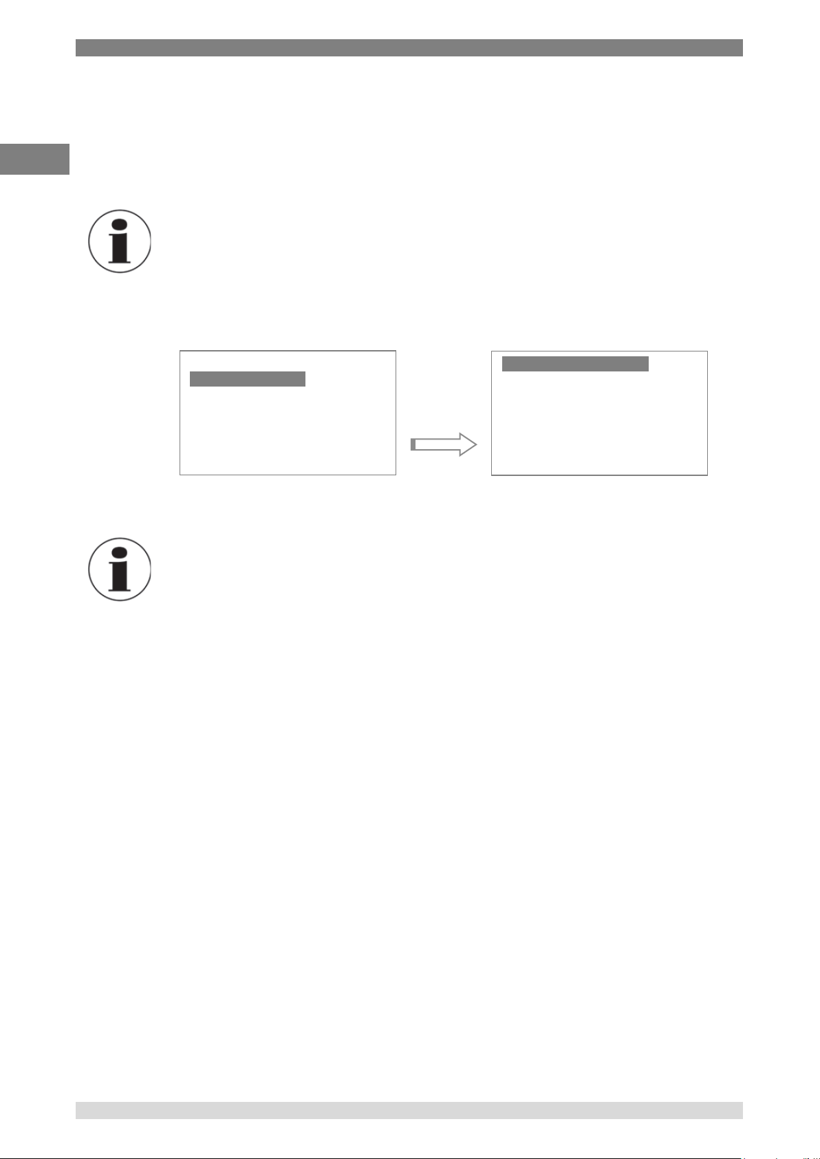
System menu
The settings menu allows the remainder of the instrument parameters to be set.
a) Change Passcode
Selecting this option allows the CTH7000 passcode to be set to another value18. The current
passcode has to be entered before it can be altered. The passcode screen will always show
the value ‘0000’ when it is first displayed; use the Up and Down keys to change this to the
current passcode value. Press Enter when the current passcode is correct. The new value
can then be set. In the example below, the passcode is ‘4300’.
18
Set to 4300 by default
Unit s
Chan nel A
Chan nel B
Logg ing
Stat ist ics
Sett ing s
Syst em
Chan ge Pas sco de
Cali bra tio n
Fact ory De fau lts
Diag nos tic s
Chan ge Pas sco de
Cali bra tio n
Fact ory D efaults
Diag nos tic s
Old c ode = 000 0
Left /Rt se lec ts
Up/D own ch ang es
Ente r OK
Curre nt = 4 300
Any key to ex it
Page 36
4. Design and Function
36 WIKA Operating Instruction, model CTH7000
EN
14240889 07/2017 EN
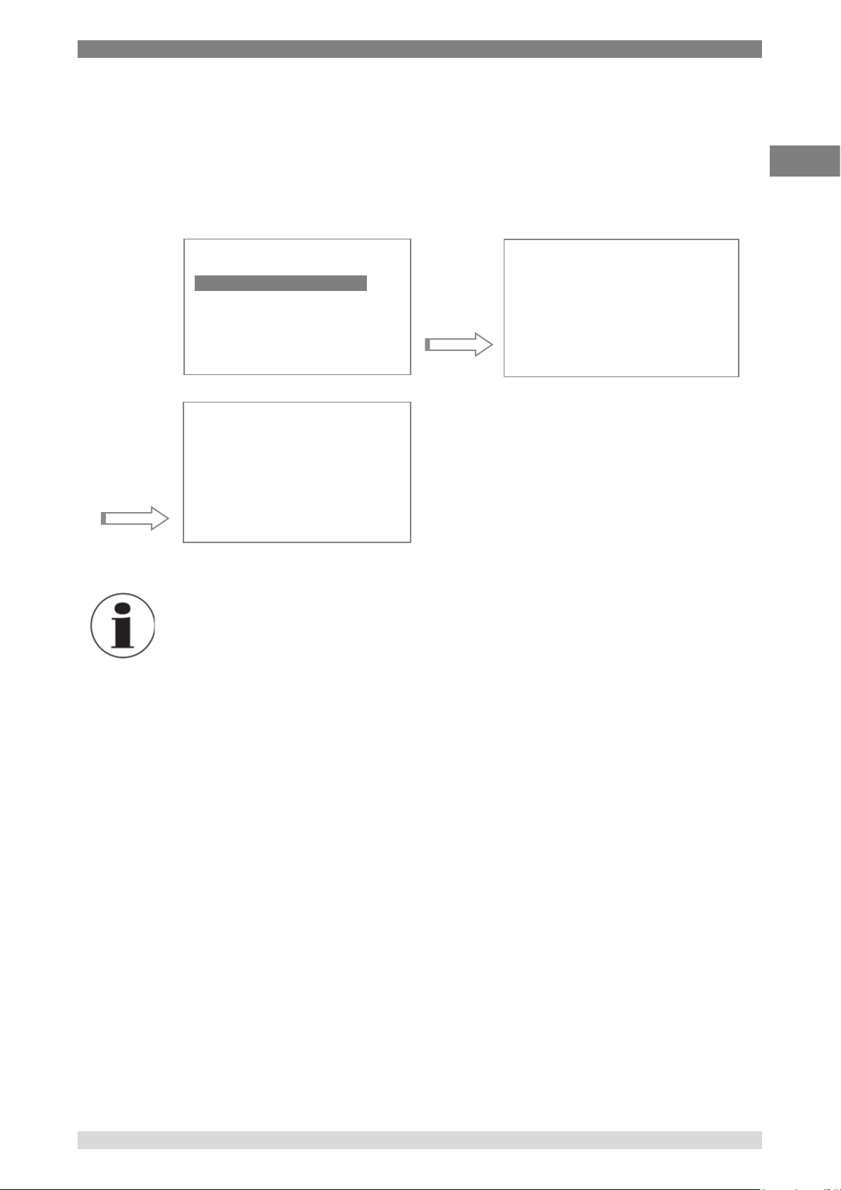
b) Instrument calibration
Selecting this option allows the CTH7000 to be calibrated; this option will overwrite and
replace the existing calibration data. The correct equipment, environment and accurately
calibrated resistors are required. For this reason, a passcode (9900) has to be entered first –
Information
Selecting this option will overwrite the instrument calibration data.
Do not attempt to do this unless you have the correct equipment,
environment and suitably trained personnel.
Information
Specialised equipment is required to proceed further with this procedure.
Chan ge Pa ssc ode
Cali bra tio n
Fact ory D efa ult s
Diag nos tic s
Do C ali bra tio n
Edit Re sis tor s
Edit Ca lib rat ion
Rese t C al
Page 37
4. Design and Function
WIKA Operating Instruction, model CTH7000 37
EN
14240889 07/2017 EN
Factory defaults
The instrument parameters can be set to the factory defaults. Selecting this option will
overwrite any exiting calibration data. For this reason, a passcode (9900) must be entered
(see below) -
Information
Selecting this option will overwrite all instrument calibration data and settings.
Do not attempt to do this unless you have the correct equipment,
environment and suitably trained personnel.
c) Diagnostics
Not available for use.
Chan ge Pa ssc ode
Cali bra tio n
Fact ory De fau lts
Diag nos tic s
Passc od e = 000 0
Left /Rt se lec ts
Up/D own ch ang es
Ente r OK
Clea r c oef f’s
Rest ore fa cto ry
defau lts ?
Ente r i f y es
Clea r f or no
Page 38
4. Design and Function
38 WIKA Operating Instruction, model CTH7000
EN
14240889 07/2017 EN
Setting up Temperature measurement
To enable accurate resistance to temperature conversion to be carried out by the instrument, PRT
or characterisation data is required for both –
temperature conversion algorithm, and
temperature conversion algorithm coefficients
For Thermistors, characterisation data is only required for –
temperature conversion algorithm coefficients
The data can be stored in either a Smart probe or the instruments’ internal non-volatile memory,
each thermometer input channel stores one set of PRT/Thermistor characterisation data. See the
relevant section above for details on entering the data.
Temperature measurement with Smart probe (s)
If a Smart probe is detected on a selected input channel, the PRT calibration data is loaded directly
from the Smart probe. Smart probe data always takes precedence over the internal CTH7000
coefficient data (but does not overwrite the instrument data).
Information
The CTH7000 may take up to 5 seconds to recognise and acquire data from
the Smart Probe after switch-on before displaying a measurement.
Instrument calibration
This is not usually a customer option; refer to separate documentation.
Firmware Version
The firmware version is shown at the bottom of the LCD when the instrument is first powered.
Page 39

4. Design and Function
WIKA Operating Instruction, model CTH7000 39
EN
14240889 07/2017 EN
Smart Probe review
The Smart probe data can be reviewed, but not changed on the CTH7000. The Smart probe data
contains the following information –
Version Smart probe data format
Lock Password protection state
00 = Smart probe data locked can not be changed from the instrument
01 = Smart probe data unlocked can be changed from the instrument
Cal type Selected method of resistance to temperature conversion algorithm to use, DIN,
ITS90, CvD or Steinhart and Hart (for thermistors)
Cal date Date of the Smart probe calibration
Due date Date the Smart probe calibration is next due
Source Company that carried out the Smart probe calibration
Serial Number Serial number of the Smart probe
Max since cal Maximum recorded temperature the Smart probe has been exposed to since
it was last calibrated (units are in resistance)
Min since cal Minimum recorded temperature the Smart probe has been exposed to since it
was last calibrated (units are in resistance)
Max ever Maximum recorded temperature the Smart probe has been exposed to during
its working life (units are in resistance)
Min ever Minimum recorded temperature the Smart probe has been exposed to during
its working life (units are in resistance)
Page 40
4. Design and Function
40 WIKA Operating Instruction, model CTH7000
EN
14240889 07/2017 EN
4.4 Instrument Measurement Range
Instrument measurement working range
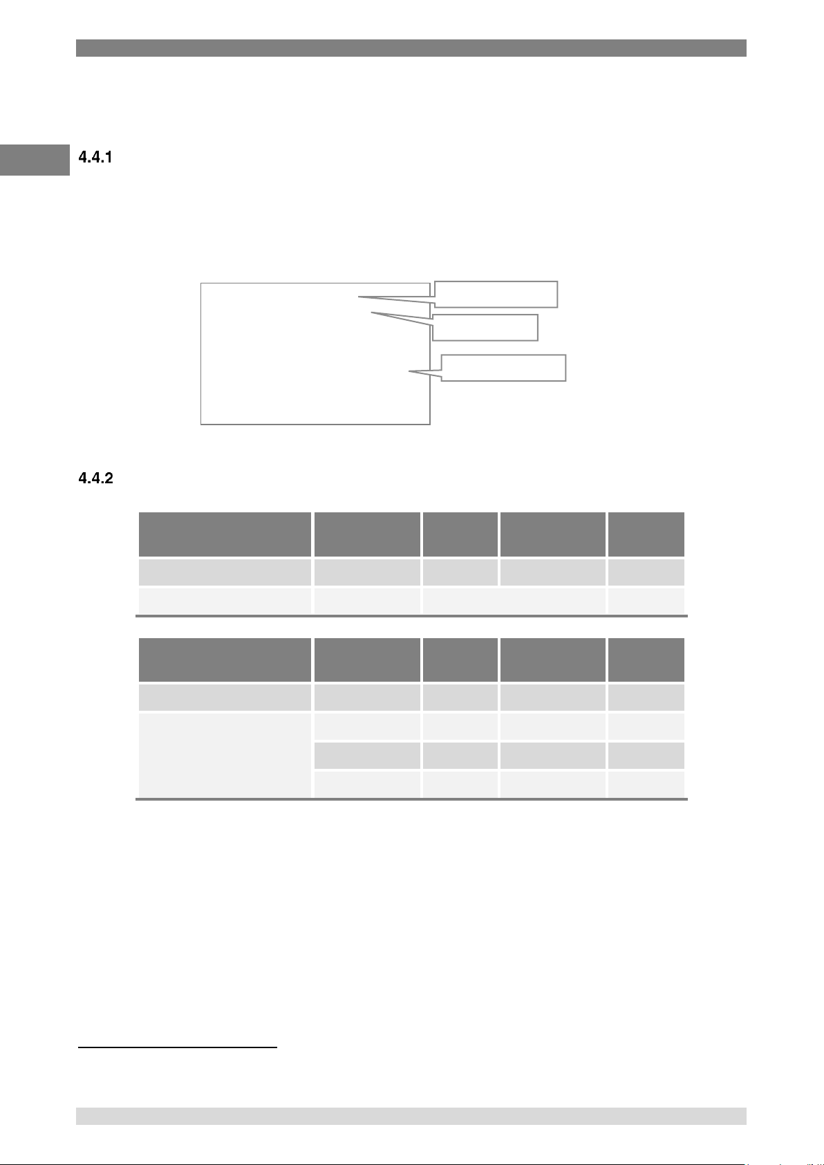
The instrument can detect the following conditions Open Circuit Probe19, Over Range measurement
and Under Range measurement. These conditions are shown by a line of dashes ‘----------‘ on the
LCD display.
Measurement Ranges
Measurement Units
Thermistor
Conversion
Under
Range
Over Range
Units
Resistance
None
0
400
ohms
Temperature
S & H
Thermistor dependent
C/F/K
Measurement Units
PRT
Conversion
Under
Range
Over Range
Units
Resistance
None
0
410
ohms
Temperature
Din90
-201°C
+851 °C
C/F/K
CvD
-201°C
+850 °C
C/F/K
ITS90
-201°C
+963 °C
C/F/K
19
Because of the potentially high resistances of thermistors, it may not be possible to determine the difference between connected and
llllldisconnected probes for these sensors.
ChA Mn - -
PRT4 M x - OV F
---------
oC
CVD Log off
No reading available
No reading available
Reading overflow
Page 41

4. Design and Function
WIKA Operating Instruction, model CTH7000 41
EN
14240889 07/2017 EN
4.5 Smart Probes
About Smart Probes
Smart probes are similar to passive probes except for one key advantage - all the probe details,
calibration data and probe history are stored within the probe itself and not within the measurement
instrument.
Smart probes can be moved freely from channel to channel or from instrument to instrument without
the need to manually enter any data into the instrument.
How Smart Probes Work
Each Smart probe if fitted with a small non-volatile memory device; this device is transparent during
normal temperature measurement.
The probe is interrogated before a measurement cycle and the probe data is read into the
instrument for use in the measurement process.
Smart Probe Data Security
To maintain a high level of data security, the Smart probe has a built in data-lock. If the data-lock is
set, the Smart probe data cannot be modified.
Smart Probe Calibration Supervisor
To assist in maintaining valid calibration, the instrument checks the Smart probe calibration date and
compares it with the instruments current date. If the Smart probe date is found to have expired, the
instrument will warn the operator ‘Probe is out of calibration’.
Smart Probe Working Range Monitor
The Smart probe working range monitor is used to monitor a Smart probes working range and to
notify a user if it is used outside its specified range.
Smart Probe Errors
Smart probe errors should never occur. They take the form – “Error 0xNN”, where NN is the error
code. Please refer to WIKA Technical Support if this error is seen.
Page 42

5. Transport, packaging and storage
42 WIKA Operating Instruction, model CTH7000
EN
14240889 07/2017 EN
5. Transport, packaging and storage
5.1 Transport
Check the instrument for any damage that may have been caused by transport.
Obvious damage must be reported immediately.
CAUTION!
Damage through improper transport
With improper transport, a high level of damage to property can occur.
▶
When unloading packed goods upon delivery as well as during internal
transport, proceed carefully and observe the symbols on the packaging.
▶
With internal transport, observe the instructions in chapter 5.2 “Packaging
and storage”.
If the instrument is transported from a cold into a warm environment, the formation of condensation
may result in instrument malfunction. Before putting it back into operation, wait for the instrument
temperature and the room temperature to equalise.
5.2 Packaging and storage
Do not remove packaging until just before mounting.
Keep the packaging as it will provide optimum protection during transport (e.g. change in installation
site, sending for repair).
Permissible conditions at the place of storage:
■
Storage temperature: -20°C … +50°C
Avoid exposure to the following factors:
■
Direct sunlight or proximity to hot objects
■
Mechanical vibration, mechanical shock (putting it down hard)
■
Soot, vapour, dust and corrosive gases
■
Hazardous environments, flammable atmospheres
Store the instrument in its original packaging in a location that fulfils the conditions listed above. If
the original packaging is not available, pack and store the instrument as described below:
1. Wrap the instrument in an antistatic plastic film.
2. Place the instrument, along with shock-absorbent material, in the packaging.
3. If stored for a prolonged period of time (more than 30 days), place a bag, containing a desiccant,
inside the packaging.
Page 43
6. Commissioning, operation
WIKA Operating Instruction, model CTH7000 43
EN
14240889 07/2017 EN
6. Commissioning, operation
Personnel: Skilled personnel
Only use original parts (see chapter 12 “Accessories”).
CAUTION!
Damage to the instrument
When working on open electrical circuits (printed circuit boards) there is a risk of
damaging sensitive electronic components through electrostatic
discharge.
▶
The correct use of grounded working surfaces and personal armbands is
required.
DANGER!
Danger to life caused by electric current
Upon contact with live parts, there is a direct danger to life.
▶
The instrument may only be installed and mounted by skilled personnel.
▶
Operation using a defective power supply unit (e.g. short-circuit from the mains
voltage to the output voltage) can result in life-threatening voltages at the
instrument!
Page 44

7. Faults
44 WIKA Operating Instruction, model CTH7000
EN
14240889 07/2017 EN
7. Faults
For contact details, please see chapter 1 “General information”
8. Maintenance, cleaning and servicing
Personnel: Service personnel
8.1 Maintenance
This instrument is maintenance-free.
Repairs must only be carried out by the manufacturer. This does not apply
to the battery replacement.
Only use original parts (see chapter 12 “Accessories”).
8.2 Recalibration
DKD/DAkkS certificate - official certificates:
We recommend that the instrument is regularly recalibrated by the manufacturer, with time intervals
of approx. 12 months. The basic settings will be corrected if necessary.
Equipment
Temperature controlled environment at +20°C ±2°C.
Set of stable, calibrated (1ppm) resistors (3 ranges, 6 resistors).
Page 45
9. Dismounting, return and disposal
WIKA Operating Instruction, model CTH7000 45
EN
14240889 07/2017 EN
9. Dismounting, return and disposal
Personnel: Skilled personnel
WARNING!
Physical injuries and damage to property and the environment through
residual media
Residual media in the dismounted instrument can result in a risk to persons, the
environment and equipment.
▶
Observe the information in the material safety data sheet for the corresponding
medium.
▶
Wash or clean the dismounted instrument, in order to protect persons and the
environment from exposure to residual media.
9.1 Dismounting
WARNING!
Physical injuries and damage to property and the environment through
residual media
Upon contact with hazardous media (e.g. oxygen, acetylene, flammable or toxic
substances), harmful media (e.g. corrosive, toxic, carcinogenic, radioactive), and
also with refrigeration plants and compressors, there is a danger of physical injuries
and damage to property and the environment.
▶
Before storage of the dismounted instrument (following use) wash or clean it, in
order to protect persons and the environment from exposure to residual media.
▶
Observe the information in the material safety data sheet for the corresponding
medium.
WARNING!
Risk of burns
During dismounting there is a risk of dangerously hot media escaping.
▶
Let the instrument cool down sufficiently before dismounting it!
DANGER!
Danger to life caused by electric current
Upon contact with live parts, there is a direct danger to life.
▶
The dismounting of the instrument may only be carried out by skilled personnel.
▶
Only disconnect the pressure measuring instrument/measuring assembly/test
and calibration installations once the system has been disconnected from the
power!
Page 46
9. Dismounting, return and disposal
46 WIKA Operating Instruction, model CTH7000
EN
14240889 07/2017 EN
9.2 Return
WARNING!
Physical injuries and damage to property and the environment through
residual media
Residual media in the dismounted instrument can result in a risk to persons, the
environment and equipment.
▶
With hazardous substances, include the material safety data sheet for the
corresponding medium.
When returning the instrument, use the original packaging or a suitable transport packaging.
To avoid damage:
1. Wrap the instrument in an antistatic plastic film.
2. Place the instrument along with shock-absorbent material in the packaging. Place shock-
absorbent material evenly on all sides of the transport packaging.
3. If possible, place a bag containing a desiccant inside the packaging.
4. Label the shipment as carriage of a highly sensitive measuring instrument.
Information on returns can be found under the heading “Service” on our local
website.
9.3 Disposal
Incorrect disposal can put the environment at risk.
Dispose of instrument components and packaging materials in an environmentally compatible way
and in accordance with the country-specific waste disposal regulations.
This marking on the instruments indicates that they must not be disposed of in
domestic waste. The disposal is carried out by return to the manufacturer or by
the corresponding municipal authorities (see EU directive 2012/19/EU).
Page 47

10. Specifications
WIKA Operating Instruction, model CTH7000 47
EN
14240889 07/2017 EN
10. Specifications
10.1 Resistance thermometer measurement
PRT characterization
ITS90
Din90 BS EN60751:1996, IEC60751:1983
Thermistor characterization
CvD BSEN1904:1984, IEC751:1983
Steinhart and Hart (NTC)
Resistance measurement range (PRT)
1 to 400 ohm
Resistance measurement range (Thermistor)
1 to 400,000 ohm
Temperature measurement range
ITS90 -200 to +962ºC
Din90 -200 to +850ºC
CvD -150 to +850ºC
Thermistor – type dependent
Accuracy (PRT)
± 0.015ºC (15mK)
Accuracy (NTC
Thermistor)
1 to 400 ohm
± 0.006 ohm
400 to 50k ohm
± 0.01% of reading
50k to 400k ohm
± 0.02% of reading
Resistance measurement uncertainty
± 6m (+20°C ±5°C)
Temperature coefficient (resistance
measurement)
0.2ppm/°C (0.05mK/°C)
Long term stability (resistance measurement)
± 25ppm (±2.5m°) / year
Sense current (PRT)
1mA (DC) polarity switchable
Sense current (NTC Thermistor)
1mA, 10μA, 3μA auto-select
User selectable measurement display units
ºC/ ºF/ K or ohms
Input channels
2
Input connection
2 x 5 pin DIN
Measurement configuration
4 wire
Input impedance
> 10M
Max common and differential mode input
voltage
±40VDC, 28Vrms
10.2 Display
User interface, display
128 x 64 LCD with (optional) backlight
Resolution
0.001 ºC
Page 48

10. Specifications
48 WIKA Operating Instruction, model CTH7000
EN
14240889 07/2017 EN
10.3 Functions
Memory
8,000 values approx
Statistical analysis
Min/max, average, standard deviation
Functions
Hold, Zero, one-shot measurement, log
Real-time clock
Integrated clock with date and year
Interface
USB
10.4 Supply
Mains charger supply voltage range
90 – 264 Vac
Power consumption
3 VA max
Supply frequency range
47 – 63 Hz
Battery supply
Nickel-Metal Hydride (Ni-MH) rechargeable
battery, low battery indicator
Battery life
20 hours of operation approx.
10.5 Environmental
Storage temperature range
-20°C to +50°C
Specified operating temperature range
0°C to +40°C
Operating relative humidity conditions
<80 % RH, non-condensing
10.6 Dimensions and weight
Dimensions
232 x 97 x 53 mm (L x W x D)
Weight
0.5 kg (1.1 lbs)
10.7 CE conformity
EMC directive
2004/108/EC, EN 61326 (group 1, class B) and
interference immunity (portable test and
measuring equipment)
Approvals and certificates, see website
For further specifications see WIKA data sheet CT 55.50 and the order documentation.
Page 49

11. Communications Interface
WIKA Operating Instruction, model CTH7000 49
EN
14240889 07/2017 EN
11. Communications Interface
11.1 Introduction
The CTH7000 is fitted with USB communication interface as standard. The connected PC
must have the correct USB driver installed. Please refer to the installation CD and the ULOG
help system.
The USB PC interface will be installed as a virtual COM driver. The communication protocol
is –
Bits per second
9600
Data bits
8
Stop bits
1
Parity
none
Flow control
none
An interval of 1 ms to 2 ms should be allowed between transmitted characters.
11.2 USB Command syntax
The programming command language is based on the SCPI command format. Commands
are case insensitive.
Commands consist of one or more command words with each command word separated by a
colon (:) or a question mark (?). For commands requiring a response, a white space character
is used to separate the command parameter from the command words (e.g. UNIT:TEMP
<units>).
A response to a command returns a list of parameters (<parameter>) with each parameter
separated by a comma (,). The last parameter will be followed by a command terminator
carriage return (CR).
: (colon)
Separates command words
? (question mark)
Command requires a response
, (comma)
Separates parameters list
Unrecognized commands will return ERR CMD after the CR character.
Command terminators (CR) or (CR)(LF)
All commands sent to the instrument must be terminated with a carriage return (CR)
character. A carriage return/line feed pair (CR)(LF) can also be sent to terminate a message;
the (LF) is ignored.
Page 50
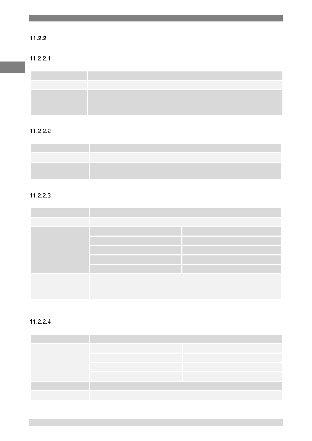
Appendix:Declaration of Conformity
50 WIKA Operating Instruction, model CTH7000
EN
14240889 07/2017 EN
Command details
SYSTEM:REMOTE
Command
SYSTEM:REMOTE
Return
None
Function
Places the CTH7000 in remote mode for USB control. CTH7000 indicates
remote on the instrument display. Disables the instrument front panel keys
(excluding backlight and power keys).
SYSTEM:LOCAL
Command
SYSTEM: LOCAL
Return
None
Function
Returns the instrument to local mode. Removes the remote indication
from the instrument display. Enables the instrument front panel keys.
*IDN?
Command
*IDN?
Return
<manufacturer>,<model no>,<serial no>,<firmware version>,<date>
Parameters
<manufacture>
ASL
<model no>
CTH7000
<serial no>
Serial number of the instrument.
<firmware version>
Current firmware version
<date>
date.
Function
Reads the instrument’s identification code consisting of the manufacturers
name, instrument model number, instrument serial number, firmware
version and date.
NB: If the serial number is not entered, the instrument will return 00000
MEASURE:CHANNEL? <channel>
Command
MEASURE:CHANNEL? <channel>
Parameters
<channel> 1 to 2
single channel measurement
<channel> -
differential measurement mode
<measurement>
last measurement value.
<units>
currently selected units.
Return
<channel>,<measurement>,<units>
Function
Responds when a measurement is available.
Page 51
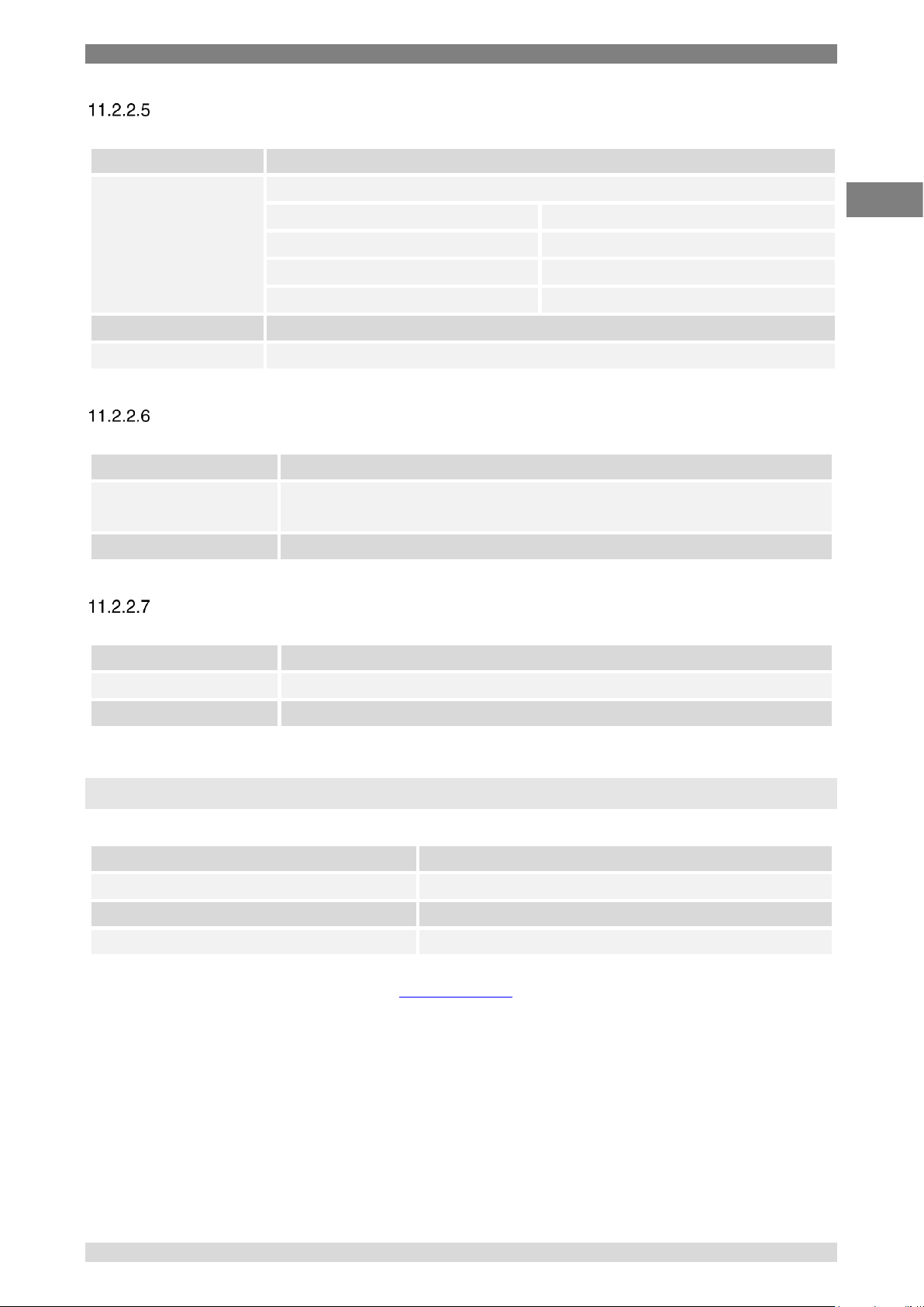
12. Accessories
WIKA Operating Instruction, model CTH7000 51
EN
14240889 07/2017 EN
UNIT:TEMP? <units>
Command
UNIT:TEMP <units>
Parameters
<units>
C or CEL
Degrees celcius
F or FAR
Degrees fahrenheit
K
Degrees kelvin
R
Resistance
Return
None
Function
Sets the temperature units.
LOG:DUMP 1
Command
LOG:DUMP 1
Return
<date>,<time>,<units>,<measurement CH1>,
<measurement CH2>,<differential>
Function
Downloads the complete CTH7000 data log.
LOG:ERASE 1
Command
LOG:ERASE
Return
<complete>
Function
Erases (clears) the complete CTH7000 data log.
12. Accessories
Spare battery pack – to clip onto rear
CTX-A-H6-Z-ZZZZBP-ZZZZ-ZZ-ZZZZ-ZZZZZZZ-Z
Replacement battery charger
CTX-A-H6-Z-ZZZZBC-ZZZZ-ZZ-ZZZZ-ZZZZZZZ-Z
Carrying case
CTX-A-H6-Z-ZZZZCC-ZZZZ-ZZ-ZZZZ-ZZZZZZZ-Z
Windows datalogger software ULog
CTX-A-H6-Z-ZZZZSG-ZZZZ-ZZ-ZZZZ-ZZZZZZZ-Z
WIKA accessories can be found online at www.wika.com.
 Loading...