

Page 1

Operating instructions
Pressure transmitter model S-20
Find Quality Products Online at: [email protected]
www.GlobalTestSupply.com
Page 2

WIKA operating instructions pressure transmitter, model S-20
14043170.06 07/2021 EN/DE/FR/ES
EN
Contents
Contents
1. General information 4
2. Safety 6
3. Specications 9
4. Design and function 15
5. Transport, packaging and storage 15
6. Commissioning, operation 16
7. Zero point adjustment 20
8. Maintenance and cleaning 21
9. Faults 22
10. Dismounting, return and disposal 23
3
Find Quality Products Online at: [email protected]
www.GlobalTestSupply.com
Page 3

WIKA operating instructions pressure transmitter, model S-20
14043170.06 07/2021 EN/DE/FR/ES
EN
1. General information
1. General information
■
The pressure transmitter described in the operating instructions has been designed and manufactured using stateof-the-art technology. All components are subject to stringent quality and environmental criteria during production.
Our management systems are certified to ISO 9001 and ISO 14001.
■
These operating instructions contain important information on handling the instrument. Working safely requires that
all safety instructions and work instructions are observed.
■
Observe the relevant local accident prevention regulations and general safety regulations for the instrument's
range of use.
■
The operating instructions are part of the product and must be kept in the immediate vicinity of the instrument and
readily accessible to skilled personnel at any time.
■
Skilled personnel must have carefully read and understood the operating instructions prior to beginning any work.
■
The manufacturer's liability is void in the event of any damage caused by using the product contrary to its intended
use, non-compliance with these operating instructions, assignment of insufficiently qualified skilled personnel or
unauthorised modifications to the instrument.
■
The general terms and conditions contained in the sales documentation shall apply.
■
Subject to technical modifications.
4
Find Quality Products Online at: [email protected]
www.GlobalTestSupply.com
Page 4

WIKA operating instructions pressure transmitter, model S-20
14043170.06 07/2021 EN/DE/FR/ES
EN
1. General information
Explanation of symbols
WARNING!
... indicates a potentially dangerous situation that can result in serious injury or death, if not avoided.
CAUTION!
... indicates a potentially dangerous situation that can result in light injuries or damage to the equipment or
the environment, if not avoided.
Information
... points out useful tips, recommendations and information for ecient and trouble-free operation.
WARNING!
... indicates a potentially dangerous situation that can result in burns, caused by hot surfaces or liquids, if
not avoided.
Abbreviations
2-wire The two connection lines are used for the voltage supply.
3-wire Two connection lines are used for the power supply.
U
U- Negative power supply terminal
S
The measurement signal also provides the supply current.
One connection line is used for the measurement signal.
Positive power supply terminal
+
Positive output terminal
+
5
Find Quality Products Online at: [email protected]
www.GlobalTestSupply.com
Page 5
WIKA operating instructions pressure transmitter, model S-20
14043170.06 07/2021 EN/DE/FR/ES
EN
2. Safety
2. Safety
WARNING!
Before installation, commissioning and operation, ensure that the appropriate pressure transmitter has been
selected in terms of measuring range, design and specic measuring conditions.
Non-observance can result in serious injury and/or damage to the equipment.
WARNING!
■
Open the connections only after the system has been depressurised.
■
Observe the working conditions in accordance with chapter 3 “Specications”.
Further important safety instructions can be found in the individual chapters of these operating instructions.
2.1 Intended use
Only use the pressure transmitter in applications that lie within the technical performance limits in particular with regard
to its material resistance and leakage rate limits, and also its permissible temperature and pressure limits.
It is the sole responsibility of the manufacturer or operator of a machine or plant to ensure the suitability of the pressure
transmitter, and its media resistance, within the application through proper choice of materials and maintenance cycles.
→ For performance limits, see chapter 3 “Specications”.
The mounting, dismounting, installation, parameterisation and maintenance of the pressure transmitter in industrial
environments absolutely requires suitably skilled personnel in accordance with chapter 2.3 “Personnel qualication”.
The instrument has been designed and built solely for the intended use described here, and may only be used
accordingly.
The manufacturer shall not be liable for claims of any type based on operation contrary to the intended use.
6
Find Quality Products Online at: [email protected]
www.GlobalTestSupply.com
Page 6

WIKA operating instructions pressure transmitter, model S-20
14043170.06 07/2021 EN/DE/FR/ES
EN
2. Safety
2.2 Improper use
Any use beyond or dierent to the intended use is considered as improper use.
The following points are in particular considered as improper use and are not permitted:
■
Use in safety or emergency stop devices
■
Unauthorized modications to the pressure transmitter
■
Use in hazardous areas
■
Use with abrasive and viscous media
2.3 Personnelqualication
WARNING!
Riskofinjuryshouldqualicationbeinsucient!
Improper handling can result in considerable injury and damage to equipment.
The activities described in these operating instructions may only be carried out by skilled personnel who
have the qualications described below.
Skilled personnel
Skilled personnel are understood to be personnel who, based on their technical training, knowledge of measurement
and control technology and on their experience and knowledge of country-specic regulations, current standards and
directives, are capable of carrying out the work described and independently recognising potential hazards.
Special operating conditions require further appropriate knowledge, e.g. of aggressive media.
2.4 Special hazards
WARNING!
For hazardous media such as oxygen, acetylene, ammable or toxic gases or liquids, and refrigeration
plants, compressors, etc., in addition to all standard regulations, the appropriate existing codes or
regulations must also be followed.
WARNING!
Residual media in dismounted pressure transmitters can result in a risk to persons, the environment and
equipment.
Take sucient precautionary measures.
7
Find Quality Products Online at: [email protected]
www.GlobalTestSupply.com
Page 7
WIKA operating instructions pressure transmitter, model S-20
14043170.06 07/2021 EN/DE/FR/ES
EN
2. Safety
2.5 Labelling / safety marks
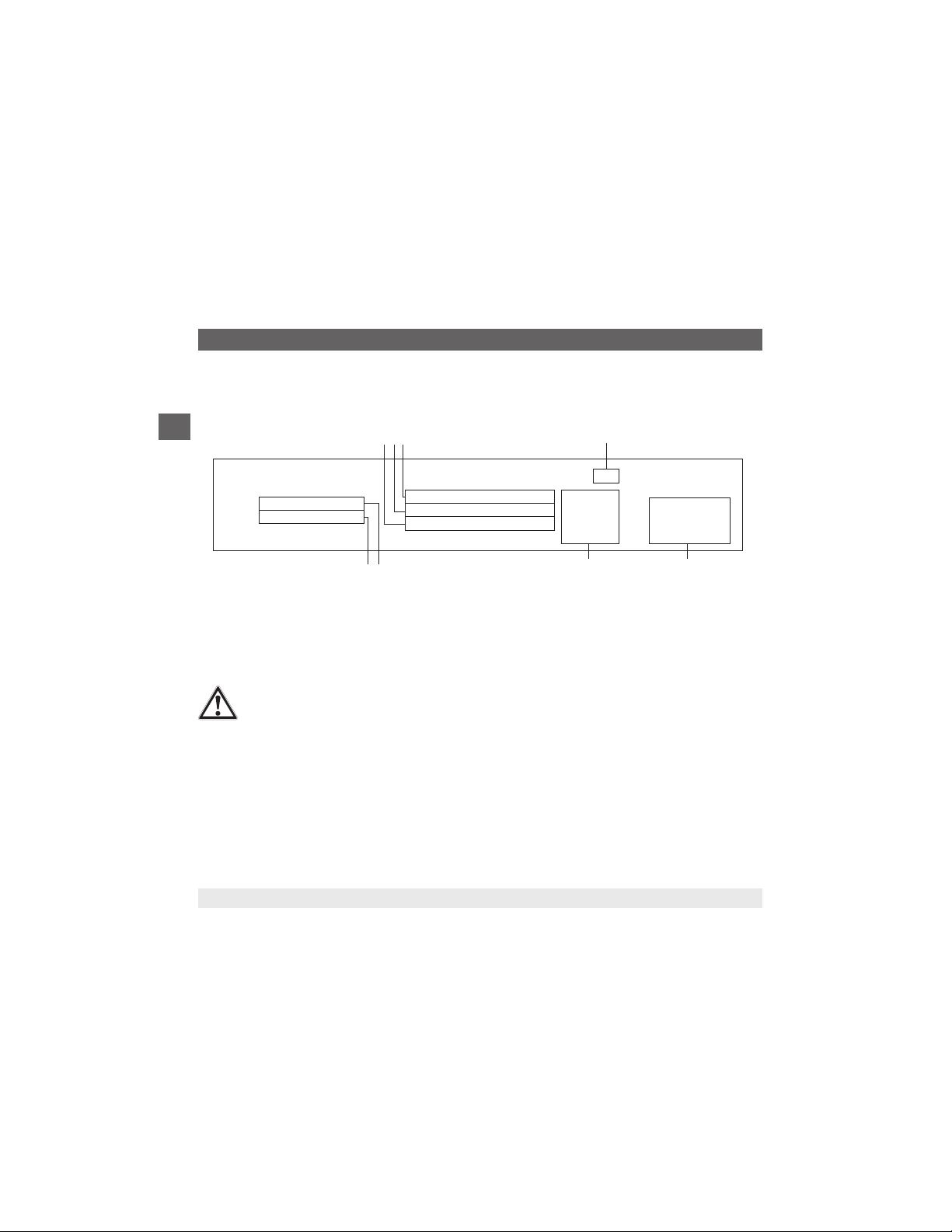
Product label
P# product numberMeasuring range
S# serial number
Power supply
Output signal
If the serial number becomes illegible due to mechanical damage or overpainting, traceability will no longer be
possible.
Before mounting and commissioning the instrument, ensure you read the operating instructions!
Approvals
Coded manufacturing date
Pin assignment
8
Find Quality Products Online at: [email protected]
www.GlobalTestSupply.com
Page 8

WIKA operating instructions pressure transmitter, model S-20
14043170.06 07/2021 EN/DE/FR/ES
EN
3.Specications
3. Specifications
Specications
Measuring range See product label or test report
Vacuum tightness Yes
Reference conditions Per IEC 61298-1
■
Temperature 15 ... 25 °C (59 ... 77 °F)
■
Atmospheric pressure 860 ... 1,060 mbar (12.5 ... 15.4 psi)
■
Humidity 45 ... 75 % r. h.
■
Power supply DC 24 V, DC 5 V with ratiometric output
■
Mounting position Calibrated in vertical mounting position with pressure connection facing downwards.
Output signal See product label or test report
Permissible load in Ω
■
Current output ≤ (power supply - 7.5 V) / 0.023 A
■
With optional settling time of 1 ms ≤ (power supply - 11.5 V) / 0.023 A
■
Voltage output > maximum output voltage / 1 mA
■
Ratiometric output
Switch-on time 150 ms
Switch-on drift 5 s (60 s with optional zero point adjustment 0.1 %)
Voltage supply See product label or test report
Dissipation loss
■
Current output 828 mW (22 mW/K derating of the dissipation loss with ambient temperatures ≥ 100 °C (212
■
Voltage output 432 mW
Current supply External circuits connected to the electrical outputs of the pressure transmitter must be
■
Current output Current signal, max. 25 mA
■
Voltage output Max. 12 mA
Non-linearity (per IEC 61298-2) See test report
Relationship to the mounting position For measuring ranges < 1 bar (15 psi), an additional zero oset of up to 0.15 % applies
Non-repeatability ≤ ±0.1 % of span
> 4.5k
°F))
energy-limited electrical circuits in accordance with section 9.4 of UL/EN/IEC 61010-1, or an
LPS to UL/EN/IEC 60950-1, or class 2 in accordance with UL1310/UL1585 (NEC or CEC).
External circuits must be suitable for operation above 2,000 m should the pressure transmitter be used at this altitude.
9
Find Quality Products Online at: [email protected]
www.GlobalTestSupply.com
Page 9

WIKA operating instructions pressure transmitter, model S-20
14043170.06 07/2021 EN/DE/FR/ES
EN
3.Specications
Specications
Temperature hysteresis 0.1 % of span at > 80 °C (176 °F)
Long-term drift (per IEC 61298-2) ≤ ±0.1 % of span
Temperature error For calibration temperature 15 ... 25 °C (59 ... 77°F)
Derating for cooling elements
■
Max. permissible ambient temperature T
■
Max. permissible medium temperature T
Storage and transport conditions
■
Permissible temperature range -40 ... +70 °C (-40 ... +158 °F)
■
Maximum humidity (per IEC 68-2-78) 67 % r. h. at 40 °C (104 °F) (in accordance with 4K4H per EN 60721-3-4)
Climate class For indoor and outdoor use. Protect the instrument from direct sunlight.
■
Storage 1K3 (per EN 60721-3-1)
■
Transport 2K3 (per EN 60721-3-2)
■
Operation 4K4H (per EN 60721-3-4, without condensation or icing)
Pollution degree 2
Overvoltage category I
Operating altitude (above sea level) ≤ 2,000 m (6.561 ft)
Vibration resistance (per IEC 68-2-6) 20 g, 10 ... 2,000 Hz (40 g, 10 ... 2,000 Hz for circular connector M12 x 1, metallic)
Continuous vibration resistance (per
IEC 68-2-6)
Shock resistance (per IEC 68-2-27) 100 g, 6 ms (500 g, 1 ms for heavy-duty connector)
Service life 100 million load cycles (10 million load cycles for measuring ranges > 600 bar/7,500 psi)
≤ ±0.2 % of span (with special measuring ranges and measuring ranges < 1 bar (15 psi))
-20 ... +80 °C: ≤1 % of span
-30 ... +100 °C: ≤1.5 % of span
For measuring ranges < 1 bar (15 psi), special measuring ranges and instruments with an
increased overpressure limit the respective temperature error increases by 0.5 % of span
(T
< 125 °C) = 125 °C
amb
med
(T
≥ 125 °C) = -0.62 x T
T
amb
med
(T
< 80 °C) = 200 °C
med
amb
(T
≥ 80 °C) = -1.61 x T
T
med
amb
T
= Ambient temperature [°C]
amb
= Medium temperature [°C]
T
med
For instruments with cooling elements a limited vibration resistance of 10 g, 10 ... 2,000 Hz,
applies.
med
amb
+ 202 °C
+ 326 °C
10 g
10
Find Quality Products Online at: [email protected]
www.GlobalTestSupply.com
Page 10

WIKA operating instructions pressure transmitter, model S-20
14043170.06 07/2021 EN/DE/FR/ES
EN
3.Specications
Specications
Free-fall test (following IEC 60721-3-2)
■
Individual packaging 1.5 m (5 ft)
■
Multiple packaging 0.5 m (1.6 ft)
■
PE bag 0.5 m (1.6 ft)
Electrical protective measures The electrical protective measures are not valid for ratiometric output signals.
■
Short-circuit resistance S+ vs. U-
■
Reverse polarity protection U+ vs. U-
■
Resistance to overvoltage DC 40 V
■
Insulation voltage DC 750 V
Materials of wetted parts
■
Relative measuring ranges Measuring ranges ≤ 10 bar (150 psi): 316L
■
Absolute measuring ranges Measuring ranges ≤ 1,000 bar (10,000 psi): ASTM 630 and 13-8 PH
Materials of non-wetted parts
■
Case 316 Ti
■
Zero point adjustment ring PBT/PET GF30
■
Angular connector DIN 175301-803 A PBT/PET GF30
■
Angular connector DIN 175301-803 C PBT/PET GF30
■
Circular connector M12 x 1 (4-pin) PBT/PET GF30
■
Circular connector M12 x 1 (4-pin,
metallic)
■
Bayonet connector (6-pin) 316L + Al
■
Field case 316L, 316Ti
■
Heavy-duty connector 316L
■
Cable outlet IP67 PA66, PBT/PET GF30
■
Cable outlet ½ NPT conduit 316L
■
Cable outlet IP68 316L
■
Cable outlet IP68, FEP 316L
■
Cable outlet IP6K9K 316L
Measuring ranges > 10 bar (150 psi): 316L + 13-8 PH
Measuring ranges > 1,000 bar (10,000 psi): 316L + 13-8 PH
316L
11
Find Quality Products Online at: [email protected]
www.GlobalTestSupply.com
Page 11

WIKA operating instructions pressure transmitter, model S-20
14043170.06 07/2021 EN/DE/FR/ES
EN
3.Specications
Specications
CE conformity
■
EM eld 30 V/m (80 ... 1,000 Mhz)
■
Performance level (per
EN ISO 13849-1:2008)
Approvals See product label
Dimensions Spanner width: 24 mm
Weight Approx. 150 g (0.331 lbs), with cooling element approx. 350g (0.794 lbs)
■
Pressure equipment directive
■
EMC directive, EN 61326 emission (group 1, class B) and interference immunity (industrial application)
■
RoHS directive
Performance level: PL = b
Category: Cat. = B
Diagnostic coverage: DC = none
MTTF: > 100 years
Diameter: 26.7
Length: 53 ... 105 mm, with cooling element additional 73 mm
12
Find Quality Products Online at: [email protected]
www.GlobalTestSupply.com
Page 12

WIKA operating instructions pressure transmitter, model S-20
14043170.06 07/2021 EN/DE/FR/ES
EN
3.Specications
Electrical connections
Electrical connection Ingress
protection
Angular connector DIN EN 175301-803 A
with mating connector IP65 max. 1.5 mm² 6 ... 8 mm - -30 ... +100 °C
with mating connector (conduit) IP65 max. 1.5 mm² - - -30 ... +100 °C
with mating connector with
moulded cable
with mating connector with
moulded cable, shielded
Angular connector DIN EN 175301-803 C
with mating connector IP65 max. 0.75 mm² 4.5 ... 6 mm- -30 ... +100 °C (-22 ... +212 °F)
with mating connector with
moulded cable
Bayonet connector (6-pin)
Circular connector M12 x 1 (4-pin)
without mating connector IP67 - - - -30 ... +100 °C
with mating connector, straight
with moulded cable
with mating connector, straight,
with moulded cable, shielded
with mating connector, angled,
with moulded cable
2) Only applies when plugged in using a suitable mating connector that has the appropriate ingress protection
IP65 3 x 0.75 mm² 6 mm PUR -30 ... +100 °C (cULus: -25 ... +85 °C)
IP65 6 x 0.5 mm² 6.8 mm PUR -25 ... +85 °C
IP65 4 x 0.5 mm² 6.2 mm PUR -25 ... +85 °C
IP67 - - - -40 ... +125 °C
IP67 3 x 0.34 mm² 4.3 mm PUR -25 ... +80 °C
,
IP67 3 x 0.34 mm² 4.3 mm PUR -25 ... +80 °C
IP67 3 x 0.34 mm² 5.5 mm PUR -25 ... +80 °C
2)
Wire
crosssection
Cable ∅Cable
material
Permissible temperature
(-22 ... +212 °F)
(-22 ... +212 °F)
(-22 ... +212 °F (cULus: -4 ... +185 °F))
(-4 ... +185 °F)
(-4 ... +185 °F)
(-40 ... +257 °F)
(-22 ... +212 °F)
(-4 ... +176 °F)
(-4 ... +176 °F)
(-4 ... +176 °F)
13
Find Quality Products Online at: [email protected]
www.GlobalTestSupply.com
Page 13

WIKA operating instructions pressure transmitter, model S-20
14043170.06 07/2021 EN/DE/FR/ES
EN
3.Specications
Electrical connection Ingress
protection
Circular connector M12 x 1 (4-pin, metallic)
without mating connector IP67 - - - -40 ... +125 °C (cULus: +85 °C)
with mating connector, straight,
with moulded cable
with mating connector, straight,
with moulded cable, shielded
with mating connector, angled, with
moulded cable
Field case
Cable outlet
Cable outlet IP67 IP67 3 x 0.34 mm² 5.5 mm PUR -30 ... +100 °C
Cable outlet ½ NPT conduit IP67 6 x 0.35 mm² 6.1 mm PUR -30 ... +100 °C (cULus: +90 °C)
Cable outlet IP68 IP68 6 x 0.35 mm² 6.1 mm PUR -30 ... +125 °C (cULus: +90 °C)
Cable outlet IP68, FEP IP68 6 x 0.39 mm² 5.8 mm FEP -40 ... +125 °C (cULus: +105 °C)
Cable outlet IP6K9K IP6K9K 6 x 0.35 mm² 6.1 mm PUR -30 ... +125 °C (cULus: +90 °C)
Heavy-duty connector
with mating connector with cable IP68 6 x 0.14 mm² 6.5 mm PUR -40 ... +125 °C (cULus: -30 ... +90 °C)
2) Only applies when plugged in using a suitable mating connector that has the appropriate ingress protection
IP67 3 x 0.34 mm² 4.3 mm PUR -25 ... +80 °C
IP67 3 x 0.34 mm² 4.3 mm PUR -25 ... +80 °C
IP67 3 x 0.34 mm² 5.5 mm PUR -25 ... +80 °C
IP6K9K - - - -25 ... +100 °C
Wire cross-
2)
section
Cable∅ Cable
material
Permissible temperature
(-40 ... +257 °F (cULus: +185 °F))
(-4 ... +176 °F)
(-4 ... +176 °F)
(-4 ... +176 °F)
(-4 ... +212 °F)
(-22 ... +212 °F)
(-22 ... +212 °F (cULus: +194 °F))
(-22 ... +257 °F (cULus: +194 °F))
(-40 ... +257 °F (cULus: +221 °F))
(-22 ... +257 °F (cULus: +194 °F))
(-40 ... +257 °F (cULus: -22 ... +194 °F))
For special model numbers, e.g. S-20000, please note the specications stated on the delivery note.
For further specications see WIKA data sheet PE 81.61 and the order documentation.
14
Find Quality Products Online at: [email protected]
www.GlobalTestSupply.com
Page 14

WIKA operating instructions pressure transmitter, model S-20
14043170.06 07/2021 EN/DE/FR/ES
EN
4. Design and function / 5. Transport, packaging and storage
4. Design and function
4.1 Description
The prevailing pressure is measured at the sensor element through the deformation of a diaphragm. By supplying
power, this deformation of the diaphragm is converted into an electrical signal. The output signal from the pressure
transmitter is amplied and standardised. The output signal is proportional to the measured pressure.
4.2 Scope of delivery
■
Pressure transmitter
■
Test report
■
Certicates (option)
■
Mating connector (option)
Cross-check scope of delivery with delivery note.
5. Transport, packaging and storage
5.1 Transport
Check the pressure transmitter for any damage that may have been caused during transportation.
Obvious damage must be reported immediately.
5.2 Packaging
Do not remove packaging until just before mounting.
Keep the packaging as it will provide optimum protection during transport (e.g. change in installation site, sending for
repair).
5.3 Storage
Permissible conditions at the place of storage:
■
Storage temperature: -40 ... +70 °C
■
Humidity: 67 % relative humidity (no condensation)
15
Find Quality Products Online at: [email protected]
www.GlobalTestSupply.com
Page 15

WIKA operating instructions pressure transmitter, model S-20
14043170.06 07/2021 EN/DE/FR/ES
EN
5. Transport, packaging and storage / 6. Commissioning, operation
Avoid exposure to the following factors:
■
Direct sunlight or proximity to hot objects
■
Mechanical vibration, mechanical shock (putting it down hard)
■
Soot, vapour, dust and corrosive gases
■
Humid or wet environment
■
Potentially explosive environments, ammable atmospheres
Store the pressure transmitter in its original packaging in a location that fulls the conditions listed above.
WARNING!
Before storing the instrument (following operation), remove any residual media. This is of particular
importance if the medium is hazardous to health, e.g. caustic, toxic, carcinogenic, radioactive, etc.
6. Commissioning, operation
6.1 Mounting the instrument
Only use the pressure transmitter if it is in perfect condition with respect to safety.
Prior to commissioning, the pressure transmitter must be subjected to a visual inspection.
■
Leaking uid is indicative of damage.
Requirements for mounting point
The mounting point must meet the following conditions:
■
Sealing faces are clean and undamaged.
■
Sufficient space for a safe electrical installation.
■
Environment corresponds to a max. pollution degree of 2.
■
For information on tapped holes and welding sockets, see Technical information IN 00.14.
■
Permissible ambient and medium temperatures remain within the performance limits. Consider possible
restrictions on the ambient temperature range caused by mating connector used.
→ For performance limits, see chapter 3 “Specifications”.
16
Find Quality Products Online at: [email protected]
www.GlobalTestSupply.com
Page 16

WIKA operating instructions pressure transmitter, model S-20
14043170.06 07/2021 EN/DE/FR/ES
EN
6. Commissioning, operation
6.1.1 Sealing the process connection
WARNING!
Risk of burns!
The cooling element can be hot as a result of previous use. Allow the cooling element to cool beforehand.
The sealing faces at the instrument have to be undamaged and clean.
Parallel threads
per EN 837
Correct sealing of the process connections with parallel
threads at the sealing face
ble at gaskets, sealing rings or WIKA prole sealings.
For further information on seals see WIKA data sheet AC 09.08
per ISO 1179-2
(formerly DIN 3852-E)
must be made using suita-
Tapered threads
NPT, R and PT
For sealing process connections with tapered threads,
the sealing must be made in the threads using additional
sealing material, e.g. PTFE tape (EN 837-2).
17
Find Quality Products Online at: [email protected]
www.GlobalTestSupply.com
Page 17
WIKA operating instructions pressure transmitter, model S-20
14043170.06 07/2021 EN/DE/FR/ES
EN
6. Commissioning, operation
6.1.2 Installing the instrument
WARNING!
Risk of burns!
The cooling element can be hot as a result of previous use. Allow the cooling element to cool beforehand.
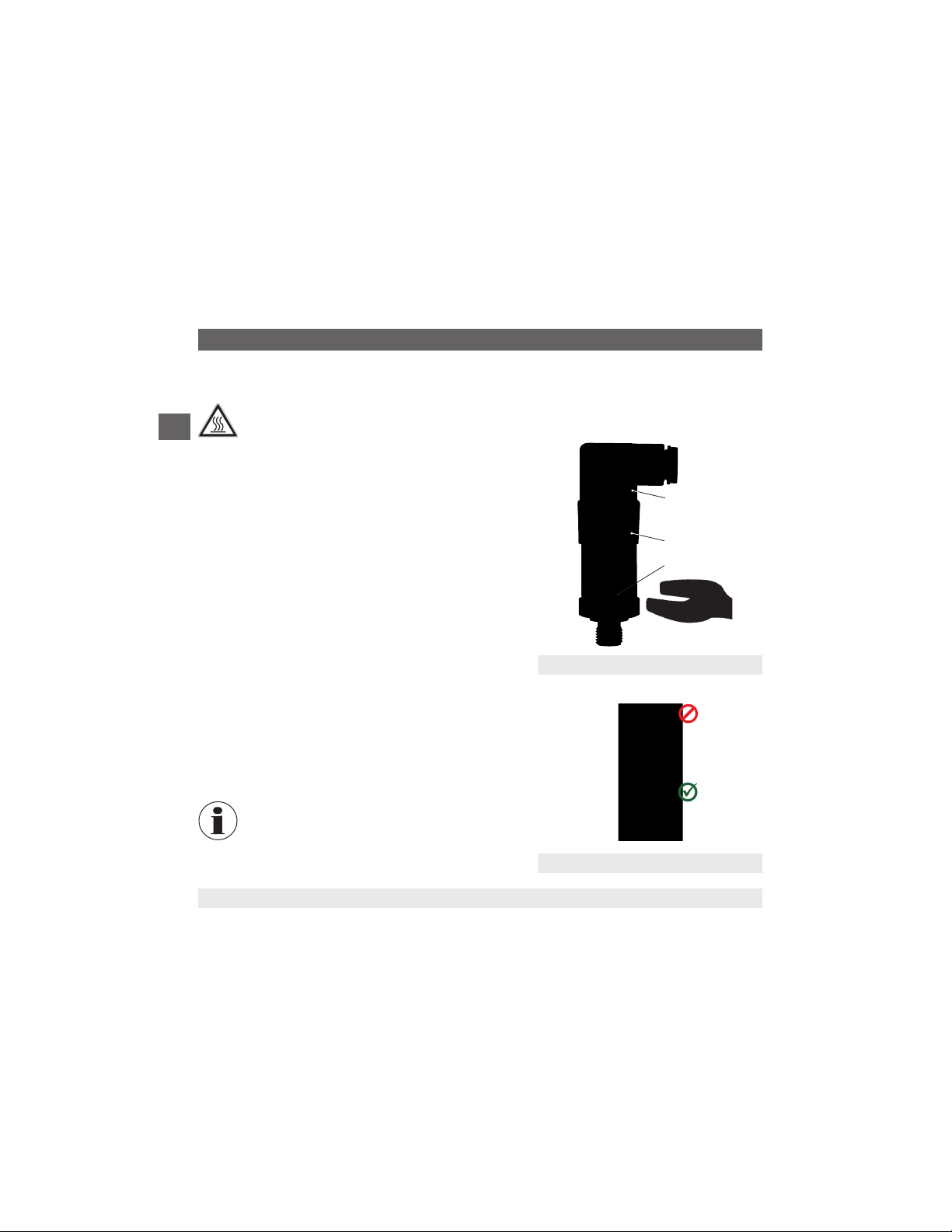
■
When screwing the instrument in, the force required to do this
must not be applied through the case or the cap ring, but only
through the spanner ats provided for this purpose and using
a suitable tool.
When there is a cooling element, the lower hexagon should
be used for tightening (see gure a "Mounting cooling
element")
The correct torque depends on the dimensions of the
process connection and the gasket used (form/material).
■
When screwing in, do not cross the threads.
■
For heat dissipation, the cooling element must not be
insulated.
■
If the instrument is mounted upside down, it must be ensured
that no water can collect on the electrical connection and on
the cap ring. Water can block the pressure compensation
diaphragm.
Electrical
connection
Cap ring
Spanner ats
Model S-20 without cooling element
For information on tapped holes and welding
sockets, see Technical information IN 00.14
Mounting a cooling element
18
Find Quality Products Online at: [email protected]
www.GlobalTestSupply.com
Page 18

WIKA operating instructions pressure transmitter, model S-20
14043170.06 07/2021 EN/DE/FR/ES
EN
6. Commissioning, operation
6.2 Electrical mounting
Only use original accessories. For accessories see data sheet PE 81.61.
WARNING!
The instrument shield does not act as a protective conductor for protection of personnel, rather as a
functional ground in order to shield the instrument from electromagnetic elds.
6.2.1 Connection assembly
■
For instruments with ratiometric output signals, a shielded cable must be used. The cable shield must be grounded,
if the cable is longer than 30 m or leaves the building.
■
Use a cable with suitable characteristics for the particular operating conditions.
■
For cable variants, strain relief must be employed.
■
Cable with ventilation tubes must be vented to atmosphere.
■
The instrument must be earthed via the process connection!
■
Select a cable diameter that matches the cable gland of the plug. Make sure that the cable gland of the mounted
plug has a tight t and that the seals are present and undamaged. Tighten the threaded connection and check that
the seal is correctly seated, in order to ensure a tight seal.
■
For cable outlets, make sure that no moisture enters at the cable end.
■
Pin assignment see test report.
6.2.2 Requirements for voltage supply
→ For supply voltage see product label
For instruments without UL approval:
This equipment is intended for operation with low voltages which are separated from the AC 230 V (50 Hz) mains
voltage or voltages greater than AC 50 V or DC 120 V for dry environments. A connection to an SELV circuit is recom-
mended, or alternatively to circuits with a dierent protective measure in accordance with IEC 60364-4-41 installation
standard.
For instruments with UL approval and for use in North America:
The power supply for the pressure switch must be made via an energy-limited electric circuit in accordance with
section 9.4 of UL/EN/IEC 61010-1, or an LPS per UL/EN/IEC 60950-1/CSA C22.2 no. 60950-1, or class 2 in
accordance with UL1310/UL1585 (NEC or CEC).
19
Find Quality Products Online at: [email protected]
www.GlobalTestSupply.com
Page 19
WIKA operating instructions pressure transmitter, model S-20
14043170.06 07/2021 EN/DE/FR/ES
EN
7. Zero point adjustment
–
+
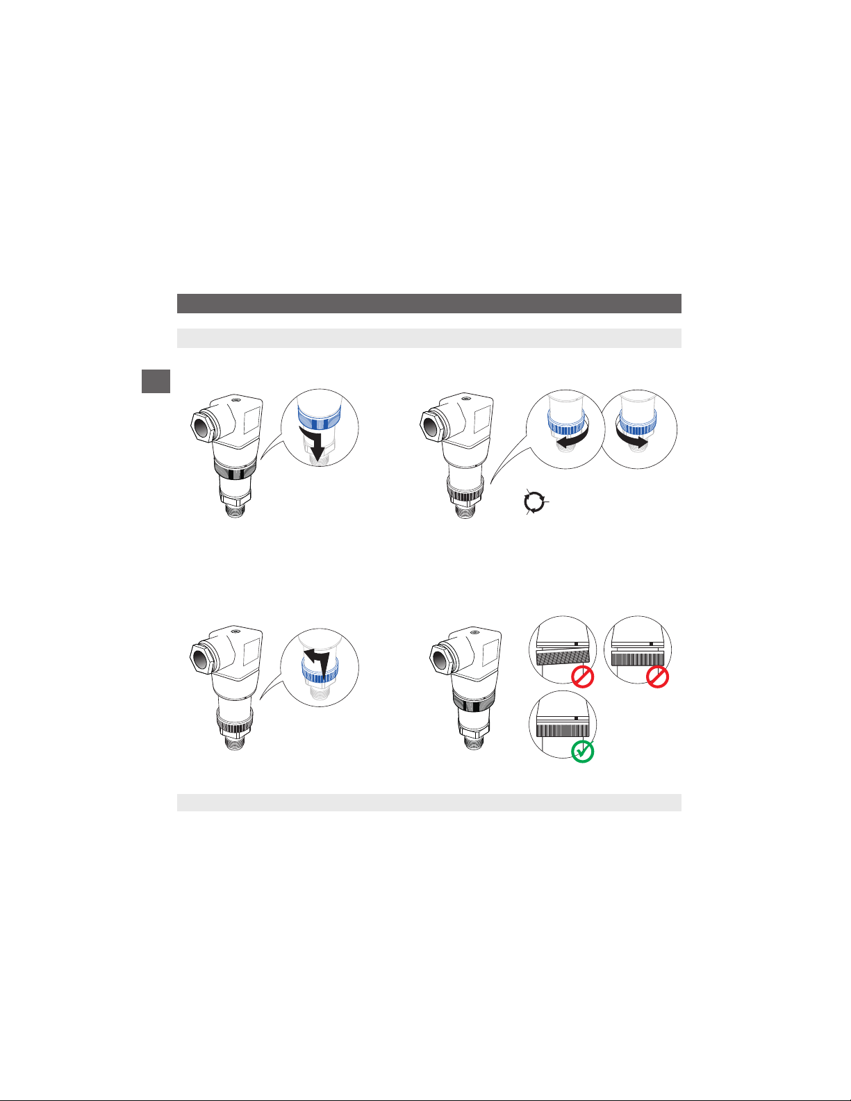
7. Zero point adjustment
1 2
3 4
20
±0,05%
±0,05%
±0,05%
120° → ±0,05%
max. ±10%
Find Quality Products Online at: [email protected]
www.GlobalTestSupply.com
Page 20

WIKA operating instructions pressure transmitter, model S-20
14043170.06 07/2021 EN/DE/FR/ES
EN
8. Maintenance and cleaning
8. Maintenance and cleaning
8.1 Maintenance
This pressure transmitter is maintenance-free.
Repairs must only be carried out by the manufacturer.
8.2 Cleaning
CAUTION!
■
Before cleaning, correctly disconnect the pressure transmitter from the pressure supply, switch it o and
disconnect it from the voltage supply.
■
Clean the instrument with a moist cloth.
■
Wash or clean the dismounted instrument before returning it, in order to protect persons and the environment from exposure to residual media.
■
Residual media in dismounted instruments can result in a risk to persons, the environment and
equipment. Take sucient precautionary measures.
■
Do not use any pointed or hard objects for cleaning, as they may damage the diaphragm of the process
connection.
For information on returning the instrument see chapter 10.2 “Return”.
8.3 Recalibration
DKD/DAkkScerticate-Ocialcerticates:
If the instrument is used for hydrogen applications, a recalibration is required after 6 months. The basic settings will be
corrected, if necessary.
21
Find Quality Products Online at: [email protected]
www.GlobalTestSupply.com
Page 21

WIKA operating instructions pressure transmitter, model S-20
14043170.06 07/2021 EN/DE/FR/ES
EN
9. Faults
9. Faults
In the event of any faults, rst check whether the pressure transmitter is mounted correctly, mechanically and electrically.
Faults Causes Measures
Plastic has faded UV radiation No measures required
No output signal Cable break Check the continuity, and if necessary
No/wrong power supply Correct the power supply
No/wrong output signal Wiring error Rectify the wiring
Constant output signal upon change
in pressure
Signal span too small/drops Mechanical overload caused by overpres-
Signal span varies/inaccurate EMC interference sources in the environ-
Deviating zero point signal Operating temperature too high/low Lower/increase the temperature
Mechanical overload caused by overpressure
sure
Diaphragm damaged, e.g. due to impacts,
abrasive/aggressive medium; corrosion at
diaphragm or process connection; transmission medium missing
Sealing/sealing face damaged/soiled,
sealing does not have a tight t, threads
jammed
ment; e.g. frequency converter
Operating temperature too high/low Lower/increase the temperature
Instrument not grounded Ground the instrument
Strongly varying pressure of the process
medium
Other mounting position Adjust the zero point
Overpressure limit exceeded Reduce the pressure
Discolouration is harmless
exchange the cable
Replace instrument; if it fails repeatedly,
contact the manufacturer
Replace instrument; if it fails repeatedly,
contact the manufacturer
Replace instrument; if it fails repeatedly,
contact the manufacturer
Clean the sealing/sealing face, replace sealing
if applicable
Shield instrument; cable shield;
Remove source of interference
Damping; consulting by the manufacturer
If complaint is unjustied, we will charge you the complaint processing fees.
22
Find Quality Products Online at: [email protected]
www.GlobalTestSupply.com
Page 22
WIKA operating instructions pressure transmitter, model S-20
14043170.06 07/2021 EN/DE/FR/ES
EN
9. Faults / 10. Dismounting, return and disposal
CAUTION!
If faults cannot be eliminated by means of the measures listed above, shut down the pressure transmitter
immediately, and ensure that pressure and/or signal are no longer present, and secure the instrument from
being put back into operation inadvertently. In this case, contact the manufacturer. If a return is needed,
please follow the instructions given in chapter 10.2 "Return".
10. Dismounting, return and disposal
WARNING!
Residual media in dismounted pressure transmitters can result in a risk to persons, the environment and
equipment. Take sucient precautionary measures.
10.1 Dismounting
WARNING!
Risk of burns!
Let the instrument cool down suciently before dismounting!
During dismounting there is a risk of dangerously hot pressure media escaping.
When removing the instrument, the force required to do this must not be applied through the case or the cap ring, but
only through the spanner ats provided for this purpose and using a suitable tool (see chapter 6.1.2 “Installing the
instrument”).
When there is a cooling element, the lower hexagon should be used for unscrewing (see chapter 6.1.2 “Installing the
instrument”)
Only disconnect the pressure transmitter once the system has been depressurised!
23
Find Quality Products Online at: [email protected]
www.GlobalTestSupply.com
Page 23
WIKA operating instructions pressure transmitter, model S-20
14043170.06 07/2021 EN/DE/FR/ES
EN
10. Dismounting, return and disposal
10.2 Return
WARNING!
Absolutely observe when shipping the pressure transmitter:
All pressure transmitters delivered to WIKA must be free from any kind of hazardous substances (acids,
bases, solutions, etc.).
When returning the instrument, use the original packaging or a suitable transport package.
Label the shipment as transport of a highly-sensitive measuring instrument in order to avoid any damage.
Information on returns can be found under the heading "Service" on our local website.
10.3 Disposal
Incorrect disposal can put the environment at risk.
Dispose of instrument components and packaging materials in an environmentally compatible way and in accordance
with the country-specic waste disposal regulations.
Do not dispose of with household waste. Ensure a proper disposal in accordance with national regulations.
24
Find Quality Products Online at: [email protected]
www.GlobalTestSupply.com
 Loading...