

Page 1
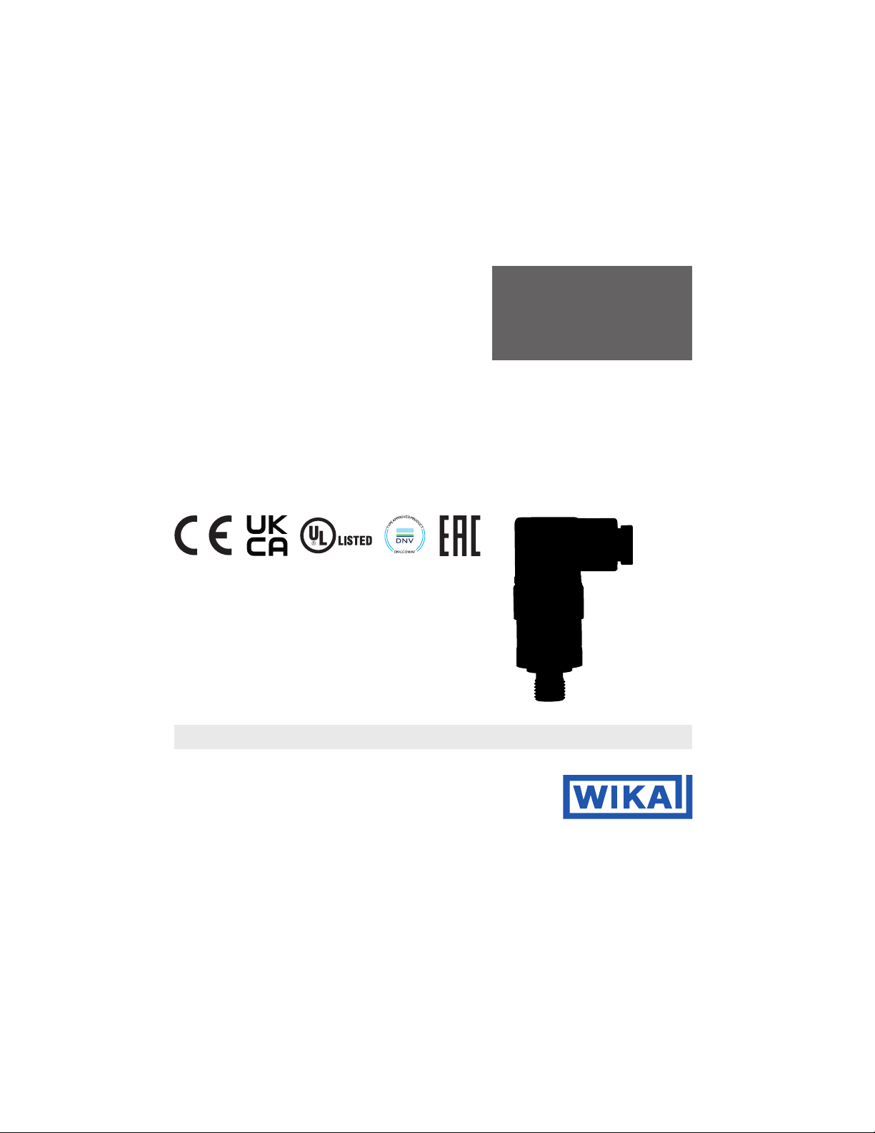
Operating instructions
Pressure transmitter, model A-10
Find Quality Products Online at: [email protected]
www.GlobalTestSupply.com
Page 2

WIKA operating instructions pressure transmitter, model A-10
EN
11218720.17 06/2023 EN/DE/FR/ES
Contents / 1. General information
Contents
1. General information 2
2. Short overview 3
3. Safety 4
4. Mounting 6
5. Faults 7
6. Maintenance 8
7. Dismounting, return and disposal 8
8. Specications 10
1. General information
■
Prior to starting any work, read the operating instructions! Keep for later use!
■
These operating instructions contain important information on handling the instrument. Working safely requires that
all safety instructions and work instructions are observed.
© 2010 WIKA Alexander Wiegand SE & Co. KG
All rights reserved.
WIKA® is a registered trademark in various countries.
2
Find Quality Products Online at: [email protected]
www.GlobalTestSupply.com
Page 3

WIKA operating instructions pressure transmitter, model A-10
EN
11218720.17 06/2023 EN/DE/FR/ES
1. General information / 2. Short overview
■ In case of a different interpretation of the translated and the English operating instructions, the English
wording shall prevail.
■
2. Short overview
2.1 Overview
Electrical connection
Case; product label
Process connection, spanner ats
Process connection, thread
3
Find Quality Products Online at: [email protected]
www.GlobalTestSupply.com
Page 4

WIKA operating instructions pressure transmitter, model A-10
EN
11218720.17 06/2023 EN/DE/FR/ES
3. Safety
3. Safety
3.1 Explanation of symbols and terms
WARNING!
The signal word indicates a hazard with a medium degree of risk which, if not avoided, may result in
death or serious injury.
CAUTION!
The signal word indicates a hazard with a low degree of risk which, if not avoided, may result in minor
or moderate injury.
Information
The signal word points out useful tips, recommendations and information for ecient and trouble-free
operation.
3.2 Intended use
The model A-10 is a pressure transmitter that is used for pressure measurement in general industrial applications. The
pressure transmitter may only be used in such applications as are within its technical performance limits, in particular
with regard to its material resistance limit, leakage rate limits and permissible temperature and pressure limits.
It is the sole responsibility of the manufacturer or operator of a machine or plant to ensure the suitability of the pressure
transmitter, and its media resistance, within the application through proper choice of materials and maintenance cycles.
(For performance limits, see chapter 8 "Specications")
The mounting, dismounting, installation, parameterisation and maintenance of the pressure transmitter in industrial
environments absolutely requires suitably skilled personnel in accordance with chapter 3.4 "Personnel qualication".
This is a class B instrument for emissions and is intended for use in industrial environments. In other environments, e.g.
residential or commercial installations, such instruments can interfere with other equipment under certain conditions. In
such circumstances the operator is expected to take the appropriate measures.
The instrument has been designed and built solely for the intended use described here, and may only be used
accordingly.
The manufacturer shall not be liable for claims of any type based on operation contrary to the intended use.
4
Find Quality Products Online at: [email protected]
www.GlobalTestSupply.com
Page 5

WIKA operating instructions pressure transmitter, model A-10
EN
11218720.17 06/2023 EN/DE/FR/ES
3. Safety
3.3 Improper use
Any use beyond or dierent to the intended use is considered as improper use. Unauthorised modications to the
instrument are not permissible.
Use in the following application areas counts as improper use:
■
Safety or emergency shutdown devices
■
Hazardous areas
■
Abrasive or viscous media and applications with hydrogen and oxygen
■
Rail vehicles, medical devices and refrigeration technology
■
Places of use that are not protected from weather inuences
■
Processes with high condensation
3.4 Personnel qualification
Skilled personnel
Skilled personnel, authorised by the operator, are understood to be personnel who, based on their technical training,
knowledge of measurement and control technology and on their experience and knowledge of country-specic
regulations, current standards and directives, must be capable of carrying out the work described and independently
recognising potential hazards.
3.5 Labelling, safety marks
Product label
Article number
Intelligent serial number
Pin assignment
Measuring range
11
Output signal
Approvals
Identification link per IEC 61406-1
Coded date of manufacture
Non-linearity
Current supply
Auxiliary power
11
5
Find Quality Products Online at: [email protected]
www.GlobalTestSupply.com
Page 6

WIKA operating instructions pressure transmitter, model A-10
EN
11218720.17 06/2023 EN/DE/FR/ES
3. Safety / 4. Mounting
Before mounting and commissioning the instrument, ensure you read the operating instructions!
DC voltage
Do not dispose of with household waste. Ensure a proper disposal in accordance with national
regulations.
4. Mounting
4.1 Mechanical mounting
Only use the pressure transmitter if it is in perfect condition with respect to safety.
Prior to commissioning, the pressure transmitter must be subjected to a visual inspection.
■ Leaking liquid is indicative of damage.
■ Obvious damage must be reported immediately.
. 4.2 Electrical mounting
Voltage supply
→ For auxiliary power, see product label
→ For further details on electrical mounting, see IN 00.50
ForinstrumentswithoutNorthAmericancertication:
This equipment is intended for operation with low voltages, which are separated from the AC 230 V (50 Hz) mains
voltage or voltages greater than AC 50 V or DC 120 V for dry environments. A connection to an SELV circuit is
recommended, or alternatively to circuits with a dierent protective measure in accordance with IEC 60364-4-41
installation standard.
6
Find Quality Products Online at: [email protected]
www.GlobalTestSupply.com
Page 7
WIKA operating instructions pressure transmitter, model A-10
EN
11218720.17 06/2023 EN/DE/FR/ES
4. Mounting / 5. Faults
ForinstrumentswithNorthAmericancerticationperUL/CSAIEC61010-1:
The power supply for the pressure transmitter must be made via a limited-energy circuit in accordance with section 9.4
of UL/IEC/EN 61010-1, or an LPS in accordance with UL/IEC/EN 60950-1/CSA C22.2 no.60950-1 or class 2 per
UL1310/UL1585 (NEC or CEC). The voltage supply must be suitable for operation above 2,000 m should the pressure
transmitter be used at this altitude.
Shielding and grounding
Include the pressure transmitter in the equipotential bonding via the process connection or connect it to ground (earth).
Pin assignment
→ For pin assignments, see product label
5. Faults
CAUTION!
Physical injuries and damage to property and the environment
If faults cannot be eliminated by means of the listed measures, the pressure transmitter must be taken
out of operation immediately.
▶
Ensure that pressure or signal is no longer present and protect against accidental commissioning.
▶
Contact the manufacturer.
▶
If a return is needed, please follow the instructions given in chapter 7.2 "Return".
For contact details, see chapter 1 “General information” or the back page of the operating instructions.
In the event of any faults, rst check whether the pressure transmitter is mounted correctly, mechanically and
electrically.
Faults Causes Measures
No output signal Cable break Check the continuity
Deviating zero point signal Overpressure limit exceeded Maintain permissible overpressure limit
7
Find Quality Products Online at: [email protected]
www.GlobalTestSupply.com
Page 8
WIKA operating instructions pressure transmitter, model A-10
EN
11218720.17 06/2023 EN/DE/FR/ES
6. Maintenance / 7. Dismounting, return and disposal
Faults Causes Measures
Deviating zero point signal Too high/low temperature of use Observe the permissible temperatures
Constant output signal upon change
in pressure
Signal span varies EMC interference sources in the
Signal span varies/inaccurate Too high/low temperature of use Observe the permissible temperatures
Signal span drops/too small Mechanical overload caused by
6. Maintenance
6.1 Maintenance
This pressure transmitter is maintenance-free.
Repairs must only be carried out by the manufacturer.
6.2 Cleaning
Only use commercially available and solvent-free cleaning agents.
7. Dismounting, return and disposal
Mechanical overload caused by
overpressure
environment, e.g., frequency converter
overpressure
Replace instrument; if it fails repeatedly,
contact the manufacturer
Use shielded cable; remove source of
interference
Replace instrument; if it fails repeatedly,
contact the manufacturer
7.1 Dismounting
WARNING!
Hazardous media
▶
8
▶
Should a failure occur, aggressive media with extremely high temperature and under high pressure
or vacuum may be present at the instrument.
Depressurise and deenergise the pressure transmitter before dismounting it.
Find Quality Products Online at: [email protected]
www.GlobalTestSupply.com
Page 9
WIKA operating instructions pressure transmitter, model A-10
EN
11218720.17 06/2023 EN/DE/FR/ES
7. Dismounting, return and disposal
7.2 Return
WARNING!
Physical injuries and damage to property and the environment through residual media
Residual media in the dismounted instrument can result in a risk to persons, the environment and
equipment.
▶
With hazardous substances, enclose the material safety data sheet for the corresponding medium.
Strictlyobservethefollowingwhenshippingtheinstrument:
All instruments delivered to WIKA must be free from any kind of hazardous substances (acids, bases, solutions, etc.)
and must therefore be cleaned before being returned.
When returning the instrument, use the original packaging or a suitable transport packaging.
Information on returns can be found under the heading “Service” on our local website.
7.3 Disposal
Incorrect disposal can put the environment at risk.
Dispose of instrument components and packaging materials in an environmentally compatible way and in accordance
with the country-specic waste disposal regulations.
Do not dispose of with household waste. Ensure a proper disposal in accordance with national
regulations.
9
Find Quality Products Online at: [email protected]
www.GlobalTestSupply.com
Page 10

WIKA operating instructions pressure transmitter, model A-10
EN
11218720.17 06/2023 EN/DE/FR/ES
8. Specications
8. Specifications
Depending on the selected instrument version (e.g. sealings), the specication may deviate from the specications
listed here. The specications in the order documentation are denitive.
For further specications, see WIKA data sheet PE 81.60.
Specifications
Measuring range → See product label
Maximum working pressure → Corresponds to the upper measuring range value/measuring range full scale value
Overpressure limit The overpressure limit is based on the measuring range. Depending on the selected
bar
bar abs. Measuring ranges ≤ 0.4 bar abs. 1 bar abs.
psi Measuring ranges ≤ 1 psi 3 psi
process connection and sealing, restrictions in overpressure limit can result.
Measuring ranges ≤ 0.1 bar 0.2 bar
Measuring ranges ≤ 0.4 bar 1 bar
Measuring ranges < 1.6 bar 3 bar
Measuring ranges ≥ 1.6 bar 2 times
Measuring range 1,000 bar 1.43 times
Measuring ranges < 1.6 bar abs. 3 bar abs.
Measuring ranges ≥ 1.6 bar abs. 2 times
Measuring ranges ≤ 5 psi 14.5 psi
Measuring ranges < 25 psi 45 psi
Measuring ranges ≥ 25 psi 2 times
Measuring ranges 160 psi, 1,000 psi,
1,500 psi and 10,000 psi
Measuring range 15,000 psi 1.43 times
1.7 times
10
Find Quality Products Online at: [email protected]
www.GlobalTestSupply.com
Page 11

WIKA operating instructions pressure transmitter, model A-10
EN
11218720.17 06/2023 EN/DE/FR/ES
8. Specications
Specifications
psi abs. Measuring ranges ≤ 5 psi abs. 14.5 psi abs.
Measuring ranges < 25 psi abs. 45 psi abs.
Measuring ranges ≥ 25 psi abs. 2 times
inWC Measuring ranges ≤ 40 inWC 80 inWC
Measuring ranges ≤ 200 inWC 400 inWC
Measuring ranges ≤ 400 inWC 1,200 inWC
inWC abs. Measuring ranges ≤ 200 inWC abs. 400 inWC abs.
Measuring ranges ≤ 400 inWC abs. 1,200 inWC abs.
Max. measured error per IEC 61298-2
Measuring range ≥ 0.6 bar [≥ 8.7 psi] ≤ ±1 % of span ≤ ±0.5 % of span
Measuring range ≥ 0.4 bar [≥ 5.8 psi] ≤ ±1.2 % of span ≤ ±0.7 % of span
Measuring range ≥ 0.25 bar [≥ 3.6 psi] ≤ ±1.3 % of span ≤ ±0.8 % of span
Measuring range ≥ 0.16 bar [≥ 2.3 psi] ≤ ±1.5 % of span ≤ ±1 % of span
Measuring range ≥ 0.1 bar [≥ 1.45 psi] ≤ ±1.8 % of span -
Measuring range ≥ 0.05 bar [≥ 0.73 psi] ≤ ±2.4 % of span -
Temperature error at 0 ... 80 °C [32 ... 176 °F]
Typical ≤ ±1 % of span
Maximum
Additionalzeropointerrordependingonthemountingpositionformeasuringranges≤1bar[15psi]
Mounting position 180°, vertical,
top process connection
Mounting position 90°, horizontal ≤ 0.6 mbar [≤ 0.009 psi]
Vacuum resistance Yes (restriction with measuring ranges ≤ 0.1 bar [≤ 1 psi, ≤ 40 inWC]: -0.2 bar [-3 psi,
■
≤ ±2.5 % of span
■
≤ ±1.5 % of span on request
≤ 1 mbar [≤ 0.015 psi]
-80 inWC])
11
Find Quality Products Online at: [email protected]
www.GlobalTestSupply.com
Page 12

WIKA operating instructions pressure transmitter, model A-10
EN
11218720.17 06/2023 EN/DE/FR/ES
8. Specications
Specifications
Output signal → See product label
Auxiliary power → See product label
Current supply → See product label
Settling time per IEC 61298-2 Measuring range ≥ 0.4 bar [≥ 5.8 psi] < 1 ms
Measuring range < 0.4 bar [< 5.8 psi] < 1 min
Switch-on time Measuring range ≥ 0.4 bar [≥ 5.8 psi] < 15 ms
Measuring range < 0.4 bar [< 5.8 psi] < 1 min
Pin assignment → See product label
Short-circuit resistance S+ vs. U-
Reverse polarity protection U+ vs. U-
Insulation voltage DC 500 V
Material (wetted)
Medium temperature limit → See order documentation or identication link per IEC 61406-1
Ambient temperature limit → See order documentation or identication link per IEC 61406-1
Storage temperature limit -40 ... +70 °C [-40 ... +158 °F]
Relative humidity 45 ... 75 % relative humidity (non-condensing)
Max. permissible altitude Above 2,000 m above sea level
Pollution degree 2
Overvoltage category I
Service life
1)
< 300 ms with DNV approval and measuring range ≥ 0.4 bar [≥ 5.8 psi] ... ≤ 0.6 bar [≤ 8.7psi]
No reverse polarity protection with ratiometric output signal
< 10 bar [150 psi] Stainless steel 316L
≥ 10 bar [150 psi] Stainless steel 316L and PH grade steel
≤ 25 bar abs. [400 psi abs.] Stainless steel 316L
Measuring range ≥ 600 bar [≥ 8,700 psi]
Measuring range > 0.1 bar [> 1.45 psi]
Measuring range ≤ 0.1 bar [≤ 1.45 psi]
1)
10 million load cycles
100 million load cycles
10 million load cycles
12
Find Quality Products Online at: [email protected]
www.GlobalTestSupply.com
Page 13
WIKA operating instructions pressure transmitter, model A-10
EN
11218720.17 06/2023 EN/DE/FR/ES
8. Specications
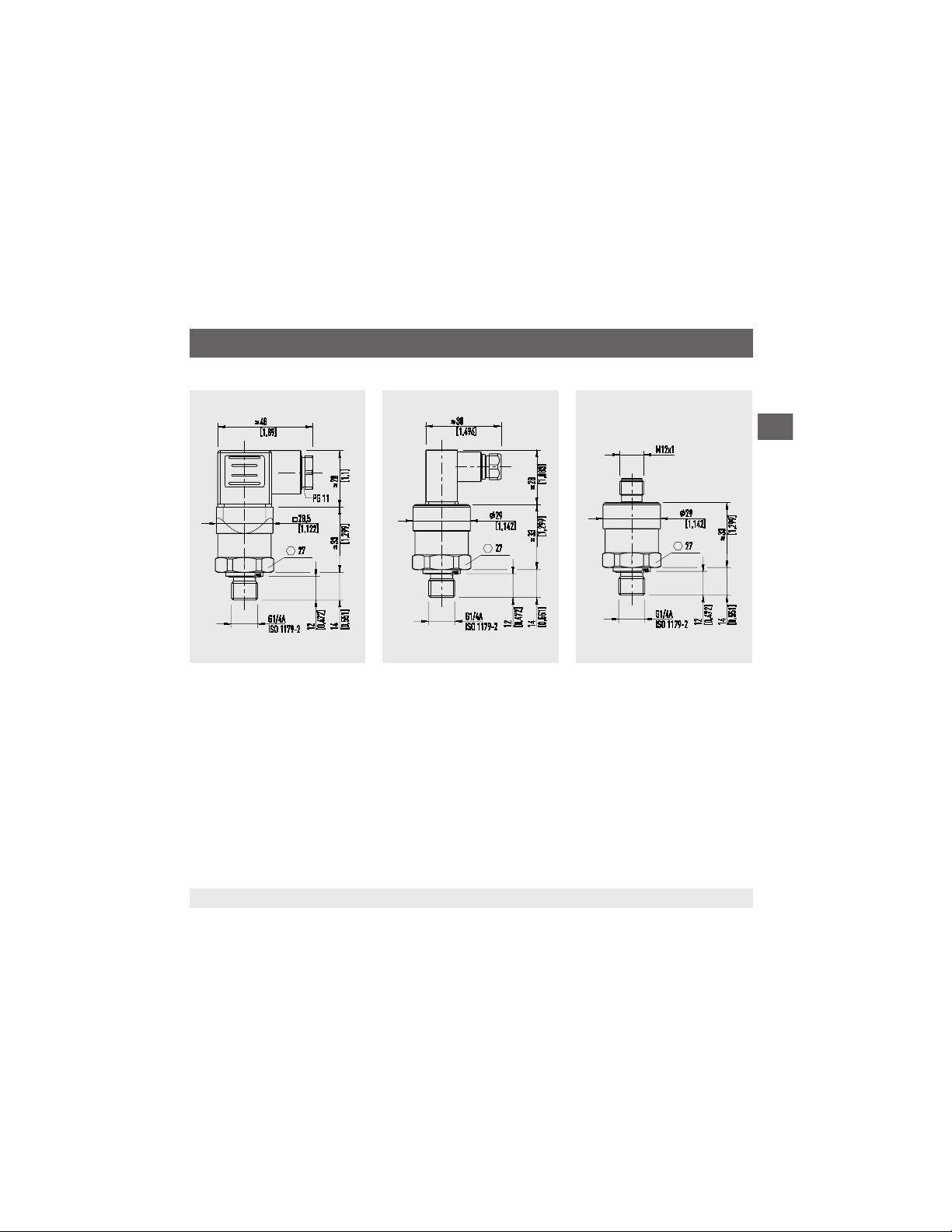
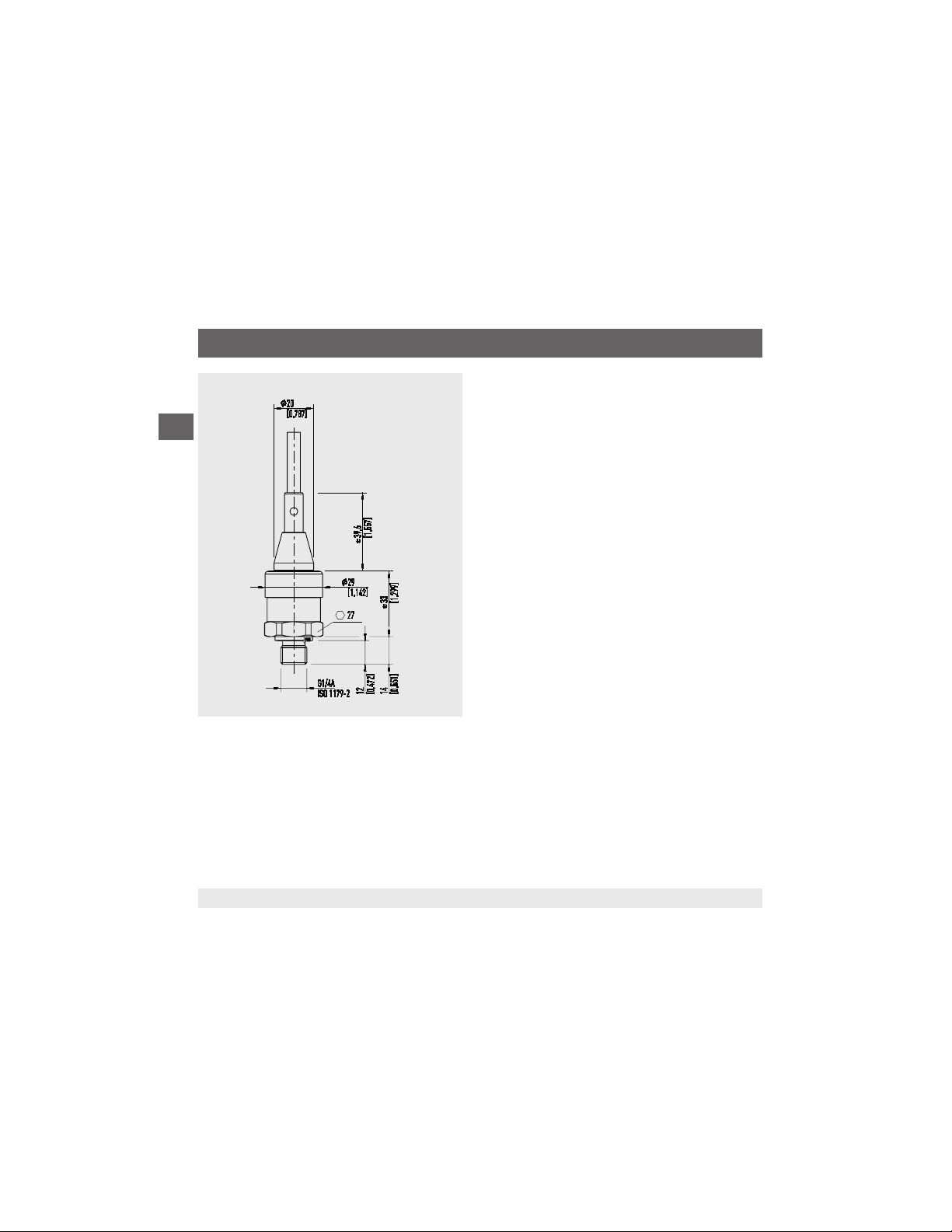
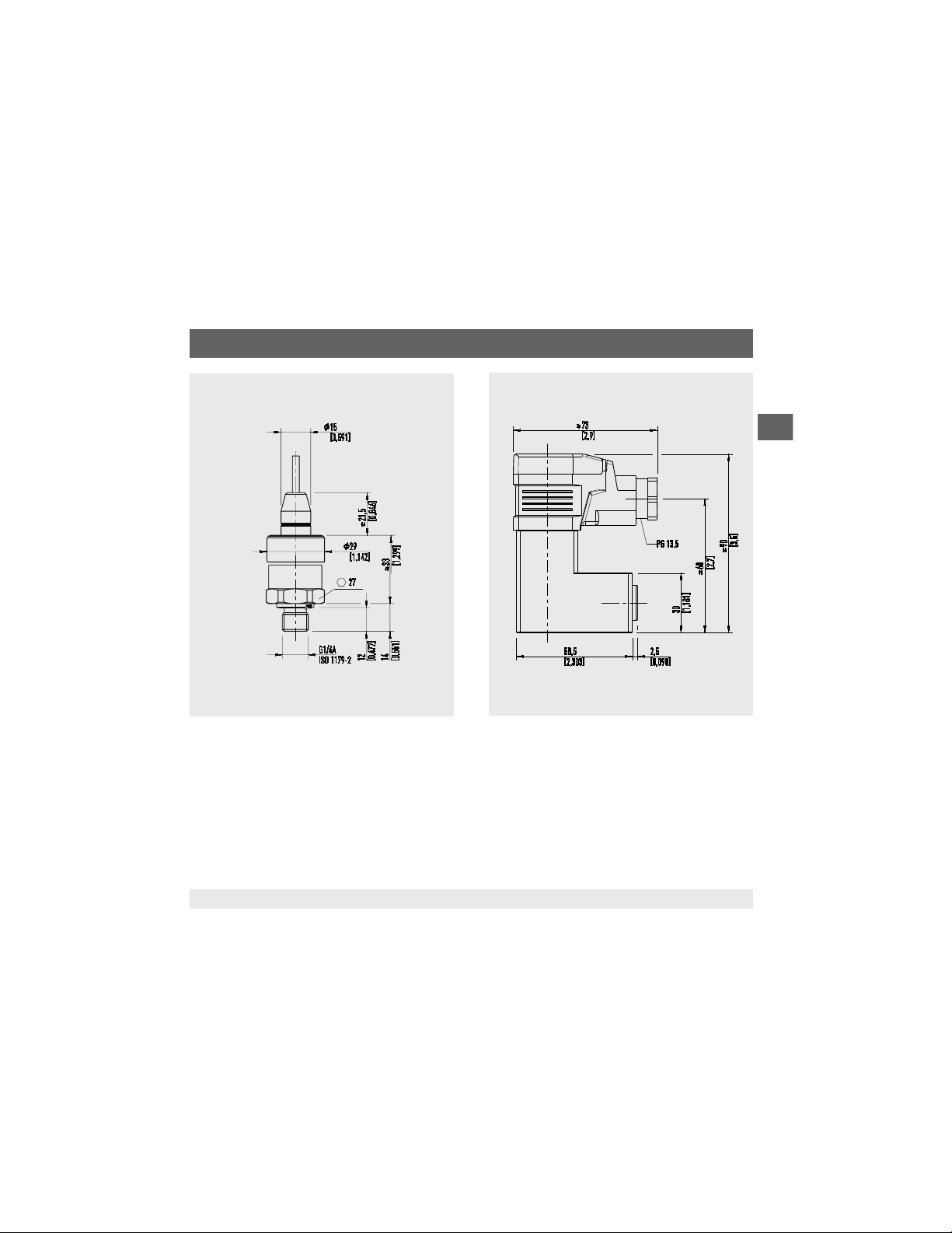
Dimensions in mm [in]
With angular connector form A With angular connector form C With circular connector M12 x 1
Weight: approx. 80 g [0.18 lb] Weight: approx. 80 g [0.18 lb]Weight: approx. 80 g [0.18 lb]
13
Find Quality Products Online at: [email protected]
www.GlobalTestSupply.com
Page 14
WIKA operating instructions pressure transmitter, model A-10
EN
11218720.17 06/2023 EN/DE/FR/ES
8. Specications
With standard cable outlet, unshielded
Weight: approx. 80 g [0.18 lb]
14
Find Quality Products Online at: [email protected]
www.GlobalTestSupply.com
Page 15
WIKA operating instructions pressure transmitter, model A-10
EN
11218720.17 06/2023 EN/DE/FR/ES
8. Specications
With cable outlet, OEM version, unshielded
Weight: approx. 80 g [0.18 lb]
With angular connector form A and ange
connection
Weight: approx. 350 g [0.77 lb]
15
Find Quality Products Online at: [email protected]
www.GlobalTestSupply.com
 Loading...