

Page 1
2408976.08 10/2022
Operating
instructions
EN
Pressure gauges
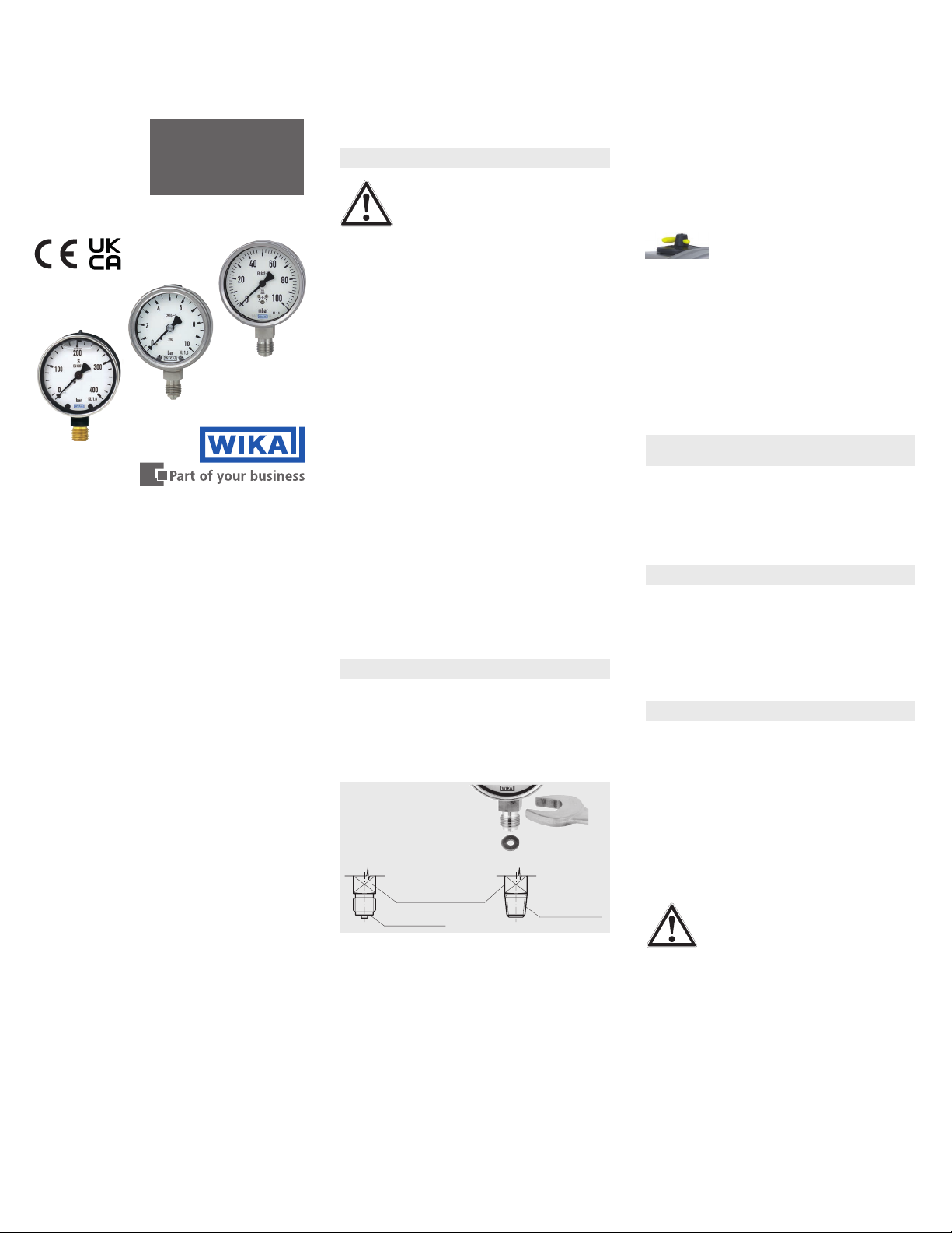
Examples:
Model 63x.50
Model 23x.50
Model 213.40
Regulations for pressure equipment
The pressure gauges are dened as “pressure
accessories”
The volume of the “pressure-bearing housings” of
WIKA pressure gauges is < 0.1 L
The pressure gauges carry conformity marking CE,
UKCA for uid group 1 per annex II, diagram 1 when
their permissible working pressure is > 200 bar
Instruments that do not carry the mark are manufactured
per article 4, paragraph 3 “sound engineering practice”.
Applicable standards (depending on model)
EN 837-1 Bourdon tube pressure gauges, dimensions,
EN 837-2 Selection and installation recommendations
EN 837-3 Diaphragm and capsule pressure gauges,
These operating instructions are only valid in conjunction
with the data sheet of the respective instrument. The
specifications given there must be observed.
Subject to technical modi
© WIKA Alexander Wiegand SE & Co. KG 2009
metrology, requirements and testing
for pressure gauges
dimensions, metrology, requirements and
testing
cations.
1. Safety
WARNING!
Before installation, commissioning and
operation, ensure that the appropriate
pressure gauge has been selected in
terms of measuring range, design and
suitable wetted material (corrosion) for the specic
measuring conditions. In order to guarantee the
measurement accuracy and long-term stability
specied, the corresponding load limits must be
observed.
The pressure measuring instruments may only be
mounted by skilled personnel and after authorisa
tion of the plant manager.
F
or hazardous media such as oxygen, acetylene,
ammable or toxic gases or liquids, and refrigera
tion plants, compressors, etc., in addition to all
d regulations, the appropriate existing
standar
codes or regulations must also be followed.
From pressure gauges which do not correspond
to a safety version per EN 837 highly pressurised
media might leak out through the possibly burst
ing window in case of a component failure.
-
For
gaseous media and working pressures > 25 bar a
pressure gauge with safety version S3 is recom
-
mended per EN 837-2.
After an e
xternal re, pressure media can leak out,
particularly at soft solder joints. All instruments
must be checked and, if necessary, replaced
before recommissioning the plant.
The safety instructions within these operating
instructions, as well as the safety, accident preven
tion and environmental protection regulations for
the application ar
ea must be maintained.
2. Mechanical connection
In accordance with the general technical regulations for pressure gauges (e.g. EN 837-2). When
scr
ewing the instruments in, the force required to
do this must not be applied through the case, but
only through the spanner ats provided for this
purpose, and using a suitable tool.
For parallel threads, use at gaskets, lens-type
Installation with
open-ended
spanner
Sealing of the pressure gauge connections
Spanner ats
Sealing face
Sealing in
the thread
sealing rings or WIKA prole sealings at the
sealing face . With tapered threads (e.g. NPT
threads), sealing is made in the threads
using
additional sealing materials, e.g. PTFE tape.
When a blow-out device is tted to a pressure
gauge, it must be protected against being blocked
by debris and dirt. With safety pressure gauges
(see
k) there must be a free space of > 20 mm
behind the blow-out back.
After installation, open the vent valve
(if present) or set from CLOSE to
OPEN. The version of the vent valve
depends on the model and can
deviate from the above illustration!
Requirements for the installation point
If the line to the measuring instrument is not
-
adequately stable, a measuring instrument holder
should be used for fastening (and possibly via a
exible capillary). If vibrations cannot be avoided
-
by means of suitable installation, instruments
with liquid lling should be used. The instruments
should be protected against coarse dirt and wide
uctuations in ambient temperature.
3. Permissible ambient and operating
temperatures
When mounting the pressure gauge it must be
ensured that, taking into consideration the inu
-
ence of convection and heat radiation, no deviation
ve or below the permissible temperature limits
abo
can occur. Observe the inuence of temperature
on the indication accuracy!
4. Storage
To protect the pressure gauges from mechanical
damage keep them in the original packaging until
installation.
Protect the measuring instruments from humidity
and dust.
Storage temperature range: -40 ... +70 °C
Storage temperature range model
PG23LT: -70 ... +70 °C
5. Maintenance and repairs
The pressure gauges are maintenance-free.
Regular checks should be carried out to ensure the
measurement accuracy.
In the case of pressure measuring instruments
with blow-out devices or safety pressure gauges,
the safety elements (e.g. blow-out plug or blowout back) must be replaced after 10 years.The
replacement may only be carried out by skilled
personnel using original parts and after authorisa
-
tion of the plant manager.
When dismounting, close the v
ent valve (if present).
WARNING! Residual media in
dismounted pressure gauges can
result in a risk to persons, the environ-
ment and equipment. Take sucient
pr
ecautionary measures.
The torque depends on the sealing used. In order
to orientate the measuring instrument so that it
can be read as well as possible, a connection with
clamp socket or union nut should be used.
Find Quality Products Online at: [email protected]
www.GlobalTestSupply.com
 Loading...