

Page 1

Operating instructions
Betriebsanleitung
Mode d’emploi
Manual de instrucciones
Ultra High Purity Transducer, models WU-20, WU-25, WU-26
Version Standard
Version Ex nA nL
WU-20
WU-25
WU-26
Page 2

GBContents
Contents Page 3 - 21
1. Important details for your information
2. A quick overview for you
3. Signs, symbols and abbreviations
4. Function
5. For your safety
6. Packaging
7. Starting, operation
8. Adjustment of zero point
9. Maintenance, accessories
10. Trouble shooting
11. Storage, disposal
12. EC declaration of conformity
Inhalt Seite 22 - 40 D
1. Wichtiges zu Ihrer Information
2. Der schnelle Überblick für Sie
3. Zeichenerklärungen, Abkürzungen
4. Funktion
5. Zu Ihrer Sicherheit
6. Verpackung
7. Inbetriebnahme, Betrieb
8. Einstellung Nullpunkt
9. Wartung, Zubehör
10. Störbeseitigung
11. Lagerung, Entsorgung
12. EG-Konformitätserklärung
GB
Contenu Page 41 - 59
1. Informations inportantes
2. Aperçu rapide
3. Explication des symboles,abréviations
4. Fonction
5. Pour votre sécurité
6. Emballage
7. Mise en service, exploitation
8. Réglage du zéro
9. Entretien, accessoires
10. Elimination de perturbations
11. Stockage, mise au rebut
12. Déclaration de Conformité
Contenido Paginás 60 - 78 E
1. Detalles importantes para su información
2. Resumen rápido para usted
3. Signos, símbolos y abreviaciones
4. Función
5. Para su seguridad
6. Embalaje
7. Puesta en servicio, funcionamiento
8. Ajuste de cero
9. Mantenimiento, accesorios
10. Eliminación de perturbaciones
11. Almacenaje, eliminación de desechos
12. Declaración de Conformidad
F
2 WIKA Operating instructions/Betriebsanleitung/Mode d'emploi/Instrucciones de servicio, WU-2X
11553678.02 GB/D/F/E 10/2012
Page 3

1. Important details for your information
Read these operating instructions without fail before installing and starting the pressure transducer
GB
1. Important details for your information
Read these operating instructions before installing and starting the pressure transducer. Keep the operating
instructions in a place that is accessible to all users at any time.
The following installation and operating instructions have been compiled by us with great care but it is not
feasible to take all possible applications into consideration. These installation and operation instructions
should meet the needs of most pressure measurement applications. If questions remain regarding a specic
application, you can obtain further information:
■
Via our Internet address www.wika.de / www.wika.com
■
The product data sheet is designated as PE 87.07
■
Contact WIKA for additional technical support (+49) 9372 / 132-8976
If the serial number on the product label gets illegible (e.g. by mechanical damage or repainting), the retraceability of the instrument is not possible any more.
WIKA transducers are carefully designed and manufactured using state-of-the-art technology. Every component undergoes strict quality and environmental inspection before assembly and each instrument is fully
tested prior to shipment. Our environmental management system is certied to DIN EN ISO 14001.
Use of the product in accordance with the intended use WU-2X:
Use the transducer to transform the pressure into an electrical signal.
For transducer with Ex-marking:
Use the nonincendive transducer of category 3G to transform the pressure into an electrical signal in hazardous areas of zone 2.
Certicate ATEX (for transducer with Ex-marking):
Transducer for operation in hazardous areas.
ATEX ratings: II 3G Ex nA nL IIC T4/T5/T6 X
11553678.02 GB/D/F/E 10/2012
3WIKA Operating instructions/Betriebsanleitung/Mode d'emploi/Instrucciones de servicio, WU-2X
Page 4
1. Important details for your information / ... / 3. Signs and symbols
Certicate FM (for transducer with FM-marking):
Transducer for operation in hazardous areas in compliance with the respective certicate (see Control
drawing No. 11537885, page 81).
FM Approval ratings: Non-incendive for Class I Division 2 Groups A, B, C and D
Knowledge required: Install and start the transducer only if you are familiar with the relevant regulations
and directives of your country and if you have the qualication required. You have to be acquainted with
the rules and regulations on hazardous areas (if transducer with Ex-marking), measurement and control
technology and electric circuits, since this transducer is „electrical equipment“ as dened by EN 60079-14.
Depending on the operating conditions of your application you have to have the corresponding knowledge,
e.g. of aggressive media.
GB
2. A quick overview for you
If you want to get a quick overview, read Chapters 3, 5, 7 and 11. There you will get some short safety
instructions and important information on your product and its starting. Read these chapters in any case.
3. Signs, symbols and abbreviations
WARNING!
Potential danger of life or of severe
injuries.
WARNING!
For transducer with Ex-marking:
Instructions for hazardous areas:
Potential danger of life or of severe
injuries.
Notice, important information,
malfunction.
4 WIKA Operating instructions/Betriebsanleitung/Mode d'emploi/Instrucciones de servicio, WU-2X
WARNING!
Potential danger of life or of severe
injuries due to catapulting parts.
CAUTION!
Potential danger of burns due to hot
surfaces.
The product complies with the
applicable European directives.
11553678.02 GB/D/F/E 10/2012
Page 5

3. Signs and symbols / 4. Function
GB
Direct voltage
For transducer with FM (Factory
Mutual) marking:
The product was tested and certied
by FM Approvals. It complies with the
applicable US-American standards
on safety (including explosion protection).
2-wire Two connection lines are intended for the voltage supply.
The supply current is the measurement signal.
3-wire Two connection lines are intended for the voltage supply.
One connection line is intended for the measurement signal.
U+ Positive supply connection
U- Negative supply connection
S+ Positive measurement connection
4. Function
Ultra High Purity Transducer
WU-20: Single End
WU-25: Flow Through
WU-26: Modular Surface Mount
ATEX
The product complies with the
requirements of the European directive
94/9/EC on explosion protection.
Function: The pressure prevailing within the application is transformed into a standardised electrical signal
through the deection of the diaphragm, which acts on the sensor element with the power supply fed to the
transducer. This electric signal changes in proportion to the pressure and can be evaluated correspondingly
11553678.02 GB/D/F/E 10/2012
5WIKA Operating instructions/Betriebsanleitung/Mode d'emploi/Instrucciones de servicio, WU-2X
Page 6
5. For your safety
GB
5. For your safety
WARNING!
■
Select the appropriate transducer with regard to scale range, performance and specic
measurement conditions prior to installing and starting the instrument.
■
Consider the relevant national regulations (e.g.: EN/IEC 60079-14) and observe the applicable
standards and directives for special applications (e.g. with dangerous media such as
acetylene, ammable gases or liquids and toxic gases or liquids and with compressors).
Non-observance can result in serious injury and/or damage to equipment.
■
Open pressure connections only after the system is without pressure!
■
Please make sure that the transducer is only used within the overload threshold limit all the
time!
■
Observe the ambient and working conditions outlined in section 7 „Technical data”.
■
Ensure that the transducer is only operated in accordance with the provisions i.e. as described
in the following instructions.
■
Do not interfere with or change the transducer in any other way than described in these
operating instructions.
■
Remove the pressure transducer from service and mark it to prevent it from being used again
accidentally, if it becomes damaged or unsafe for operation
■
Take precautions with regard to remaining media in removed pressure transducers.
Remaining media in the pressure port may be hazardous or toxic!
■
Have repairs performed by the manufacturer only.
■
The operator is responsible for the material compatibility as well as correct handling, operation
and maintenance.
Information about material consistency against corrosion and diusion can be found in our WIKA-Handbook,
"Pressure and Temperature Measurement".
WARNING!
For transducer with Ex-/FM-marking: Consider the relevant safety instructions as well as
the respective country specic regulations for installation and operation in hazardous areas
(e.g.: IEC 60079-14, NEC). If you do not observe these stipulations, serious injuries and/or
damage may occur.
6 WIKA Operating instructions/Betriebsanleitung/Mode d'emploi/Instrucciones de servicio, WU-2X
11553678.02 GB/D/F/E 10/2012
Page 7

6. Packaging
6. Packaging
Has everything been supplied?
Check the scope of supply:
■
Completely assembled transducer
■
Inspect the transducer for possible damage during transportation. Should there be any
obvious damage, inform the transport company and WIKA without delay.
■
The UHP transducers are puried, evacuated and double-packed in clean rooms in a protective atmosphere (clean room class 5 according to ISO 14644). Special plastic protective
caps are used to protect the high-quality threaded connections (ttings). The gauges should
remain in this special packaging until installation in order to prevent damage and contamination. Therefore remove the ESD (Electro-Static-Discharge) protective foil only at the place of
installation.
■
Keep the packaging, as it oers optimal protection during transportation (e.g. changing
installation location, shipment for repair).
■
Ensure that the pressure connection thread and the connection contacts will not be damaged.
■
Remove this protection cap only just before installing the transducer.
■
Mount the protection cap when removing and transporting the instrument.
Unpack the transducer
1. Remove the transducer from the box.
2. Remove the outer protective bag and discard.
3. Carry the transducer (sealed in the inner bag), into the clean area.
GB
11553678.02 GB/D/F/E 10/2012
7WIKA Operating instructions/Betriebsanleitung/Mode d'emploi/Instrucciones de servicio, WU-2X
Page 8
7. Starting, operation
7. Starting, operation
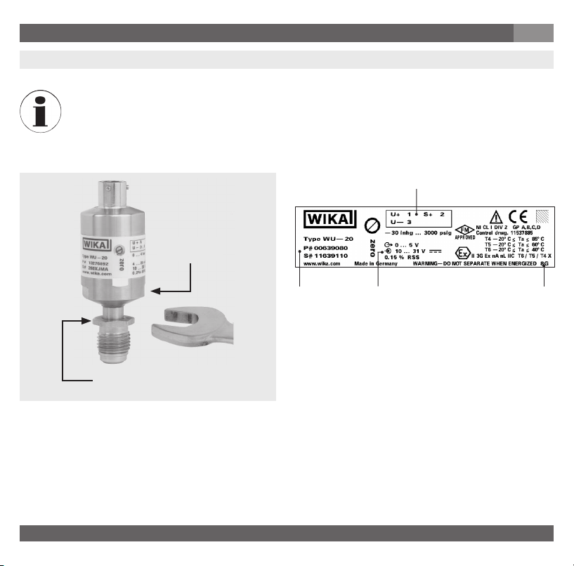
Required tools: wrench (ats 19 and 16), screw driver (0.040" to 0.060" / 1 to 1.5 mm) and a pair
of scissors, allen key for WU-26
Mechanical connection Product label (example)
PIN assignment
Don't use this
spanner at!
GB
P # Product No.
S # Serial No.
Signal
Power Supply
Coded manufacture date
Use this spanner at
for screwing in!
8 WIKA Operating instructions/Betriebsanleitung/Mode d'emploi/Instrucciones de servicio, WU-2X
11553678.02 GB/D/F/E 10/2012
Page 9
7. Starting, operation
■
Remove the protection cap only just before installation.
■
When mounting the instrument, ensure that the sealing faces of the instrument and the
measuring point are clean and undamaged.
■
Do not scratch or nick the bead. Do not over tighten. Damage to the bead will aect the
tting's performance and may cause leakage in the system.
■
Screw in or unscrew the instrument only via the ats using a suitable tool and the prescribed
torque. The appropriate torque depends on the dimension of the pressure connection and on
the sealing element used (form/material). Do not use the case as working surface for screwing
in or unscrewing the instrument.
■
When screwing the transmitter in, ensure that the threads are not jammed.
WARNING!
For transducer with Ex-/FM-marking:
■
Protect the inner diaphragm against any contact with abrasive substances and pressure
peaks and do not touch it with tools. Damage of the diaphragm may result in losing the
explosion protection.
■
Observe the technical data for the use of the transducer in connection with aggressive /
corrosive media and for the avoidance of mechanical hazards.
Mechanical Connection
■
Prepare the gas line connections appropriately.
■
You should blow clean all tting components (such as sealing gaskets, for example) using a clean/ltered
gas. Please refer to the specic technical guides furnished by the gasket manufacturers for additional
specications.
■
You can then remove the protective lm, as well as any plastic caps there may be for protecting high-quality
ttings.
GB
11553678.02 GB/D/F/E 10/2012
9WIKA Operating instructions/Betriebsanleitung/Mode d'emploi/Instrucciones de servicio, WU-2X
Page 10

7. Starting, operation
GB
Face Seal Connections (only WU-20, WU-25)
For connections compatible with VCR®-ttings:
1. Hold the swivel female face seal / swivel male face seal, mounting part (valve etc.) or case hexagon. Tighten the swivel female face seal hand-tight and adjust the instrument to the desired position. When tightening or untightening at mounting parts (valves etc.) or ttings, ensure that the threads do not get jammed.
2. Hold the swivel female face seal with a suitable open-end wrench. Tighten the swivel female face seal /
swivel male face seal or mounting part (valve etc.) by a 1/8 or 1/4 turn (depending on the sealing elements
used) beyond the hand-tight position.
3. Please refer to the specic technical guides furnished by the tting manufacturers for additional specications.
4. With that the transducer is mechanically connected. Electrical connection possibilities are described in the
following section.
Welding Connections (only WU-20, WU-25)
The weld needs to be fully penetrating, but amperage and heat need to be minimised. We recommend
owing Argon gas through the transducer during welding. This will help to cool the transducer. Prior to
welding tubing to the transducer, it is recommended that a few test welds be made.
WARNING!
■
Make sure the transducer is not connected to any other device, prior to arc welding.
■
Disconnect the transducer from any electrical device.
■
The operator is responsible for the material compatibility as well as correct handling, operation and maintenance.
Prepare the transducer for use
1. Adjust the zero point (please refer to chapter Zero Adjustment).
2. Verify integrity of the weld or seal by appropriate helium leak-testing procedures.
3. Turn the gas ow ON then OFF, 10 times to remove any particles generated during
installation. (The ow rate used should at least equal the process ow specications.)
MSM, Modular Surface Mount (only WU-26)
Please observe the corresponding technical specications, such as torques and mounting position of the
contact components.
10 WIKA Operating instructions/Betriebsanleitung/Mode d'emploi/Instrucciones de servicio, WU-2X
11553678.02 GB/D/F/E 10/2012
Page 11

7. Starting, operation
Electrical connection
WARNING!
Connect the enclosure to ground through the process connection, against electromagnetic
elds and electrostatic discharge.
WARNING!
Specic conditions for safe use in explosive atmosphere:
■
External earthing connection shall be established by end-user via pressure connection
minimum 4 mm² required. External earthing connection shall be corrosion resist and locked
against rotation.
■
Suitable connector minimum IP 54 shall be provided by end-user (In the end-use application
the degree of protection min IP54 shall be maintained). If applicable the connector shall be in
accordance with EN 60079-0:2006 and EN 60079-15:2005
■
Cable provided by end-user shall be suitable for the ambient temperature.
■
Use only shielded cables. Note that with connectors no connection between cable shield
and housing is possible.
For instruments with cable outputs, the cable is always shielded. Depending upon the design
(ordered version) the screen may or may not be connected with the enclosure. An additional
equipotential bonding maybe required.
■
Ensure that the cable diameter you select ts to the cable gland of the connector Ensure that
the cable gland of the mounted connector is positioned correctly and that the sealings are
available and undamaged. Tighten the threaded connection and check the correct position
of the sealings in order to ensure the ingress protection
■
Cover ying leads with ne wires by an end splice (cable preparation).
■
Please make sure that the ends of cables with ying leads do not allow any ingress of
moisture.
■
The transducer must be connected and operated in accordance with the approriate regulations. Take care to ensure that the electrical connection (e.g. M12 connector) is correctly
made (fully sealed).
GB
11553678.02 GB/D/F/E 10/2012
11WIKA Operating instructions/Betriebsanleitung/Mode d'emploi/Instrucciones de servicio, WU-2X
Page 12
7. Starting, operation
GB
WARNING!
■
For equipment with Ex nA nL certication, or if operated under nA nL conditions: Do not
separate when energized.
■
For products with FM Approval: The connection between cable and connector shall
withstand a tensile force of min. 15 N
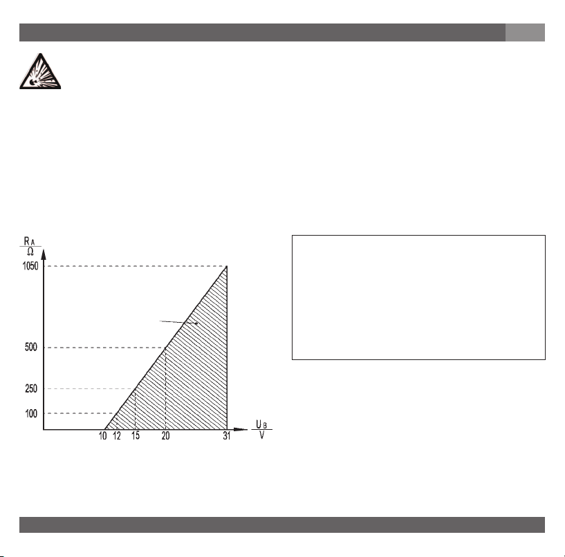
The transducer is designed to operate with an input voltage of 10 ... 31 VDC / 14 ... 31 with output signal
0 ... 10 V. The voltage value Ui = 31 VDC shall not be exceeded in the current loop circuit. The interrelationship between voltage supply and load resistor (RA) is illustrated by the following diagram.
Signal output and allowed load
4 ... 20 mA, 2-wire
Current output (2-wire)
4 ... 20 mA:
RA ≤ (U+ – 10 V) / 0,02 A
Voltage output (3-wire)
permitted range
0 ... 5 V: RA > 5 kOhm
0 ... 10 V: RA > 10 kOhm
with RA in Ohm and U+ in Volt
Current for external display- or evaluation equipment can be supplied directly from the circuit, when operating a transducer with current output. A voltage drop specic to the display unit is to be considered. The
UHP-display unit of type (N)WUR-1 has a specic voltage drop of 6 V. The transducers are short-circuit-proof
for a short time, but anyhow any incorrect connection of the instrument should be avoided.
12 WIKA Operating instructions/Betriebsanleitung/Mode d'emploi/Instrucciones de servicio, WU-2X
11553678.02 GB/D/F/E 10/2012
Page 13
7. Starting, operation
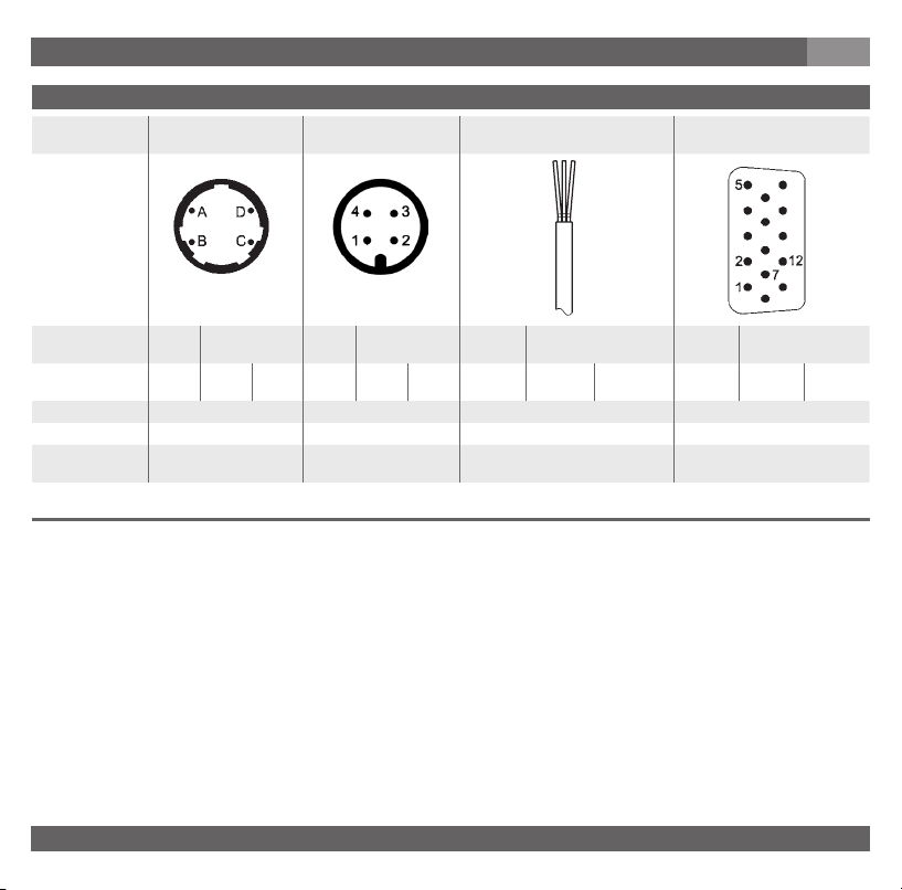
Wiring details
Bayonet connector,
4-pin
Circular connector
M12 x 1, 4-pin
GB
Flying leads, 1.5 m Sub-D HD connector, 15-pin
2-wire U+ = A U- = D U+ = 1 U- = 3 U+ = red U- = black U+ = 7
3-wire U+ = A U- = D S+ = B U+ = 1 U- = 3 S+ = 4 U+ = red U- = black S+ = brown U+ = 7
2
Wire gauge - - 0.22 mm
Diameter of cable - - 4.8 mm Ingress Protection
per IEC 60529
11553678.02 GB/D/F/E 10/2012
IP 67 (NEMA 4) IP 67 (NEMA 4) IP 67 (NEMA 4) IP 54
The ingress protection classes specied only apply while the pressure transmitter is connected with female connectors that
provide the corresponding ingress protection.
(AWG 24) -
U- = 5
U- = 12
U- = 5
U- = 12
S+ = 2
13WIKA Operating instructions/Betriebsanleitung/Mode d'emploi/Instrucciones de servicio, WU-2X
Page 14

7. Starting, operation
GB
Specications Models WU-20, WU-25 and WU-26
Pressure ranges psi 14.5 25 60 100 160 250 350 500 1000 1500
WU-26
Over pressure safety *
Burst pressure *
)
)
bar 1 1.7 4 7 11 17 25 36 70 100
psi 120 120 120 210 320 500 750 1100 2100 3000
psi 1800 1800 1800 2200 2600 4800 6200 5800 8000 10500
Pressure ranges psi 2000 3000 5000
Over pressure safety *
Burst pressure *
)
)
bar 145 225 360
psi 4200 6600 10500
psi 10500 10500 12000
Other pressure ranges, pressure units (e.g. MPa, kg/cm
)
1 psi = 0.069 bar
*
Measuring principle Metal thin-lm sensor
Materials
■
Wetted parts
- Pressure Connection 316L VIM/VAR
- Pressure sensor 2.4711 / UNSR 30003
■
Case 304 SS
Particle test ≤ 0.1 µm Particle 0.1 ptc / ft³ according to Semi E49.8
Inboard helium leak test < 1 x 10
Surface nish Electropolished, typical Ra ≤ 0.13 µm (RA 5); max. Ra ≤ 0.18 µm (RA 7) exceeds Semi F19
Dead volume cm
3
-9
mbar l/sec (atm STD cc/sec) according to Semi F1
WU-20 < 1.5, WU-25 < 1, WU-26 < 1
Permissible Medium Special gas / Vapour / Liquid
Power supply U+ U+ in VDC 10 ... 31 with output signal 4 ... 20 mA / 0 ... 5 V
14 ... 31 with output signal 0 ... 10 V
Signal output and RA in Ohm 4 … 20 mA, 2-wire RA ≤ (U+ – 10 V) / 0.02 A
maximum ohmic load RA 0 ... 5 V, 3-wire RA > 5 k
0 ... 10 V, 3-wire RA > 10 k
Power Pi W 1
Adjustability zero % of span -3.5 up to +3.5 (via potentiometer) Current output signal
-2 up to +3.5 (via potentiometer) Voltage output signal
WU-20 / WU-25
2
) and absolute pressure on request
14 WIKA Operating instructions/Betriebsanleitung/Mode d'emploi/Instrucciones de servicio, WU-2X
11553678.02 GB/D/F/E 10/2012
Page 15

7. Starting, operation
GB
Specications Models WU-20, WU-25 and WU-26
Response time (10 ... 90 %) ms ≤ 300
Insulation voltage VDC 500
Accuracy % of span ≤ 0.15 (≤ 0.4 with pressure ranges ≤ 2 bar) RSS (Root Sum Squares) according
Non-linearity % of span ≤ 0.1 (≤ 0.15 for pressure ranges ≤ 2 bar) (BFSL) according to IEC 61298-2
Hysteresis % of span ≤ 0.14
Non-repeatability % of span ≤ 0.12
1-year stability % of span ≤ 0.25 typ. (at reference conditions)
Permissible temperature of non-Ex T4 T5 T6
■
Medium °C -20 ... +100 °C -20 ... +85 °C -20 ... +60 °C -20 ... +40 °C
■
Ambience °C -20 ... +85 °C -20 ... +85 °C -20 ... +60°C -20 ... +40 °C
■
Storage °C -40 ... +100 °C -40 ... +100 °C -40 ... +100 °C -40 ... +100 °C
■
Medium °F -4 ... +212 °F -4 ... +185 °F -4 ... +140 °F -4 ... +104 °F
■
Ambience °F -4 ... +185 °F -4 ... +185 °F -4 ... +140 °F -4 ... +104 °F
■
Storage °F -40 ... +212 °F -40 ... +212 °F -40 ... +212 °F -40 ... +212 °F
Rated temperature range -20 ... +80 °C / -4 ... +176 °F (active compensated)
Temperature coecients within rated tempera-
ture range (active compensated)
■
Mean TC of zero % of span ≤ 0.1 / 10 K
■
Mean TC of range % of span
RoHS-conformity Yes (not with bayonet connector)
CE- conformitiy
■
Pressure equipment directive 97/23/EC
■
EMC directive
■
Directive ATEX of equipment intended for
use in potentially explosive atmospheres
Ex-protection ATEX Category **
Ignition protection type II 3G Ex nA nL IIC T4/T5/T6 X (for transducer with Ex-marking)
to Semi # 3440 draft
≤ 0.3 (≤ 0.6 with pressure ranges ≤ 2 bar) BFSL
≤
0.15 / 10 K
2004/108/EC, EN 61 326 Emission (Group 1, Class B) and Immunity (industrial
locations)
94/9/EC (for transducer with Ex-marking)
)
3G (for transducer with Ex-marking)
)
Read the operating conditions and safety-relevant data in the operating
**
instructions.
11553678.02 GB/D/F/E 10/2012
15WIKA Operating instructions/Betriebsanleitung/Mode d'emploi/Instrucciones de servicio, WU-2X
Page 16
7. Starting, operation
GB
Specications Models WU-20, WU-25 and WU-26
Ex-protection FM Class I (for transducer with FM-marking)
Ignition protection type Nonincendive for Use in Class I, Division 2, Groups A, B, C & D, and Class I, Zone 2,
Assembly and packing area Clean room class 5 according to ISO 14644
Packaging Double bagging according to SEMI E49.6
Shock resistance 500 (1.5 ms) according to IEC 60068-2-27
Vibration resistance 0.35 mm (10 - 58 Hz) / 5 g (58.1 - 2000 Hz) according to IEC 60068-2-6
Wiring protection
■
Short-circuit proofness S+ towards U-
■
Reverse polarity protection U+ towards UWeight kg Approx. 0.1
Group IIC, Hazardous (Classied) Locations
When designing your plant, take into account that the stated values (e.g.burst pressure, over
pressure safety) apply depending on the material, thread and sealing element used.
Functional test
The output signal must be proportional to the pressure. If not, this might point to a damage of the diaphragm.
In that case refer to chapter 10 „Troubleshooting“.
WARNING!
■
Open pressure connections only after the system is without pressure!
■
Observe the ambient and working conditions outlined in section 7 „Technical data.
■
Please make sure that the transducer is only used within the over load threshold limit at all
times!
CAUTION!
When touching the transducer, keep in mind that the surfaces of the instrument components
might get hot during operation.
16 WIKA Operating instructions/Betriebsanleitung/Mode d'emploi/Instrucciones de servicio, WU-2X
11553678.02 GB/D/F/E 10/2012
Page 17
8. Adjustment of zero point
GB
8. Adjustment of zero point
The UHP-Transducers are maintenance free. The transducer is factory calibrated and does not normally need
eld adjustment.
WARNING!
For equipment with Ex nA nL marking, or if operated under nA nL conditions: Do not separate
when energised.
For verication and adjustment of the zero point, vent the transducer to zero (0)PSI for gage reference transducers. Use a 0.040" to 0.060" (1 to 1.5 mm) jeweler's screwdriver for adjustment.
■
For instruments with absolute pressure measuring ranges or +/- measuring ranges, a
sucient calibration equipment as well as a vacuum pump are also necessary for the zero
point adjustment.
■
Span adjustment is not necessary after zero point correction.
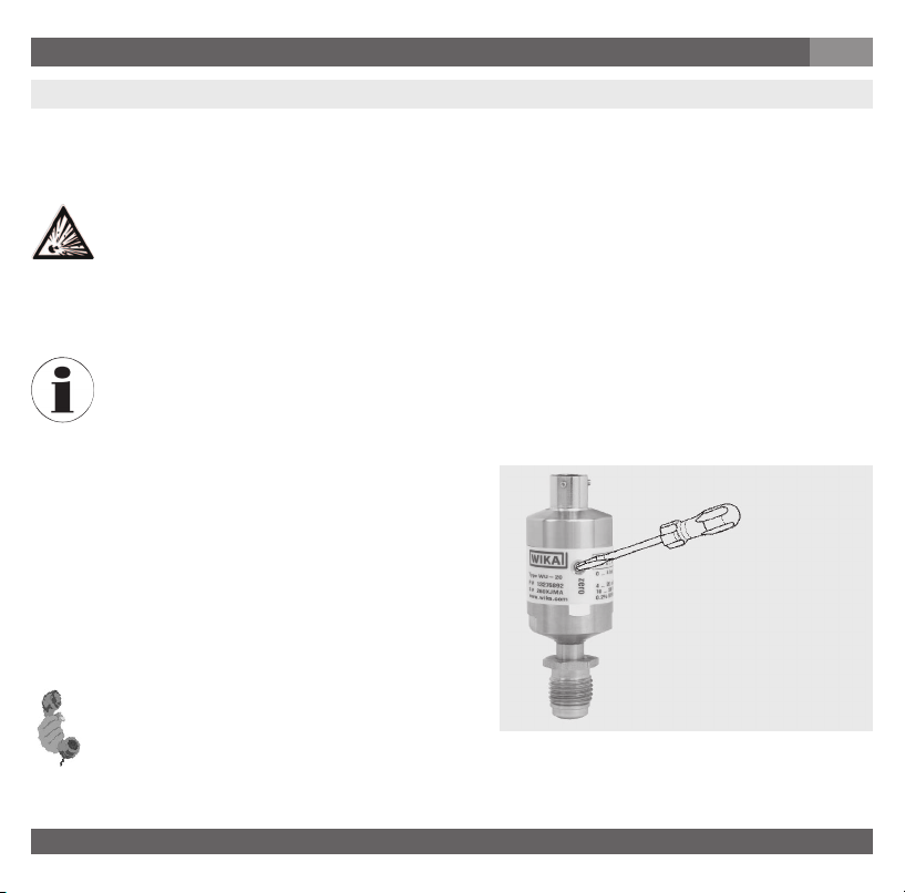
Procedure
1. Restore power to the transducer.
2. Lift the sticker.
3. Adjust the zero point by means of the potentiometer
in pressureless state. Check the zero point by means
of a suitable instrument. Clockwise rotation means an
upward zero oset, anti-clockwise rotation means a
downward zero oset.
4. Push the sticker on.
For further information
(+49) 9372/132-8976
11553678.02 GB/D/F/E 10/2012
17WIKA Operating instructions/Betriebsanleitung/Mode d'emploi/Instrucciones de servicio, WU-2X
Page 18
9. Maintenance, accessories / 10. Trouble shooting
GB
9. Maintenance, accessories
■
WIKA transducers require no maintenance.
■
Have repairs performed by the manufacturer only.
Accessories: For details about the accessories (e. g. connectors), please refer to WIKA‘s price list, WIKA‘s
product catalog on CD or or contact our sales department.
10.Trouble shooting
WARNING!
Open pressure connections only after the system is without pressure!
WARNING!
■
Take precautions with regard to remaining media in removed transducers. Remaining media
in the pressure port may be hazardous or toxic!
■
Remove the transducer from service and mark it to prevent it from being used again accidentally, if it becomes damaged or unsafe for operation.
■
Have repairs performed by the manufacturer only.
Do not insert any pointed or hard objects into the pressure port for cleaning to prevent damage
to the diaphragm of the pressure connection.
Please verify in advance if pressure is being applied (valves/ ball valve etc. open) and if the right voltage
supply and the right type of wiring (2-wire/3-wire) has been chosen?
18 WIKA Operating instructions/Betriebsanleitung/Mode d'emploi/Instrucciones de servicio, WU-2X
11553678.02 GB/D/F/E 10/2012
Page 19

10. Trouble shooting
GB
Failure Possible cause Procedure
Output signal unchanged after change in
pressure
No output signal No/incorrect voltage supply or current spike
No/False output signal Incorrectly wired (e.g. Connected as 2-wire
Abnormal output signal or abnormal zero point
signal
Abnormal zero point signal Medium or ambient temperature too high/
Signal span dropping o/too small Diaphragm is damaged, e.g. through impact,
Signal span too small Power supply too high/too low
*) Make sure that after the setting the unit is working properly. In case the error continues to exist send in the instrument for reparation (or replace
the unit).
Mechanical overload through overpressure
Wrong supply voltage or current spike
Cable break
instead of 3-wire system)
Zero point set wrongly Adjust zero point correctly (see chapter 8); a
too low
Diaphragm is damaged, e.g. through impact,
abrasive/agressive media; corrosion of
diaphragm/pressure connector.
abrasive/agressive media; corrosion of
diaphragm/pressure connector
Mechanical overload through overpressure
Replace instrument; if failure reoccurs, consult
the manufacturer *)
Replace instrument
Adjust the voltage supply to correspond with
the Operating Instructions *)
Check connections and cable
Follow pin assignment (see Instrument Label /
Operating Instructions)
suciently accurate current/volt meter should
be used
Control the internal temperature of the instrument within the permissible range; observe the
allowable temperature error (see Operating
Instructions)
Replace instrument
Contact the manufacturer and replace the
instrument
Correct the power supply in line with the
Operating Instructions
Re-calibrate the instrument *)
In case of unjustied reclamation we charge the reclamation handling expenses.
11553678.02 GB/D/F/E 10/2012
19WIKA Operating instructions/Betriebsanleitung/Mode d'emploi/Instrucciones de servicio, WU-2X
Page 20

10. Trouble shooting / 11. Storage, disposal
If the problem persists, contact our sales department.
USA, Canada: If the problem continues, contact WIKA or an authorized agent for assistance. If the pressure
transducer must be returned obtain an RMA (return material authorization) number and shipping instructions
from the place of purchase. Be sure to include detailed information about the problem. Pressure transducers
received by WIKA without a valid RMA number will not be accepted.
Process material certicate (Contamination declaration for returned goods)
Purge / clean dismounted instruments before returning them in order to protect our employees and the
environment from any hazard caused by adherent remaining media.
Service of instruments can only take place safely when a Product Return Form has been submitted and
fully lled-in. This Return Form contains information on all materials with which the instrument has come into
contact, either through installation, test purposes, or cleaning. You can nd the Product Return Form on our
internet site (www.wika.de).
GB
11. Storage, disposal
WARNING!
When storing or disposing of the transducer, take precautions with regard to remaining media in
removed transducers. We recommend cleaning the transducer properly and carefully. Remaining media in the pressure port may be hazardous or toxic!
Storage
Mount the protection cap when storing the transducer.
Disposal
Dispose of instrument components and packaging materials in accordance with the respective
waste treatment and disposal regulations of the region or country to which the instrument is
supplied.
20 WIKA Operating instructions/Betriebsanleitung/Mode d'emploi/Instrucciones de servicio, WU-2X
11553678.02 GB/D/F/E 10/2012
Page 21

12. EC declaration of conformity
12. EC declaration of conformity
GB
Original see Page 79
WIKA reserves the right to alter these technical specications.
11553678.02 GB/D/F/E 10/2012
21WIKA Operating instructions/Betriebsanleitung/Mode d'emploi/Instrucciones de servicio, WU-2X
Page 22

1. Wichtiges zu Ihrer Information
Lesen Sie unbedingt diese Betriebsanleitung vor Montage und Inbetriebnahme des Druckmessgerätes.
D
1. Wichtiges zu Ihrer Information
Lesen Sie diese Betriebsanleitung vor Montage und Inbetriebnahme des Druckmessgerätes.
Bewahren Sie die Betriebsanleitung an einem für alle Benutzer jederzeit zugänglichen Ort auf.
Die nachfolgenden Einbau- und Betriebshinweise haben wir mit Sorgfalt zusammengestellt. Es ist jedoch
nicht möglich, alle erdenklichen Anwendungsfälle zu berücksichtigen. Sollten Sie
Aufgabenstellung vermissen, können Sie hier weitere Informationen nden:
■
Über unsere Internet-Adresse www.wika.de / www.wika.com
■
Die Bezeichnung des zugehörigen Datenblattes ist PE 87.07
■
Anwendungsberater: (+49) 9372/132-8976
Wird die Seriennummer auf dem Typenschild unleserlich (z. B. durch mechanische Beschädigung oder
Übermalen), ist eine Rückverfolgbarkeit nicht mehr möglich.
Die in der Betriebsanleitung beschriebenen WIKA-Transducer werden nach den neuesten Erkenntnissen
konstruiert und gefertigt. Alle Komponenten unterliegen während der Fertigung strengen Qualitäts- und
Umweltkriterien. Unser Umweltmanagementsystem ist nach DIN EN ISO 14001 zertiziert. Das fertige Gerät
wurde vor dem Versand getestet, gereinigt und sorgfältig unter Schutzatmosphäre verpackt.
Bestimmungsgemäße Produktverwendung WU-2X:
Verwenden Sie den Transducer, um Druck in ein elektrisches Signal zu wandeln.
Für Transducer mit Ex-Kennzeichen: Verwenden Sie den nicht funkenden Transducer der Kategorie 3G, um
in explosionsgefährdeten Bereichen der Zone 2, Druck in ein elektrisches Signal zu wandeln.
Hinweise für Ihre spezielle
ATEX (für Transducer mit Ex-Kennzeichen): Transducer zur bestimmungsgemäßen Verwendung in explosionsgefährdeten Bereichen. ATEX Kennzeichen: II 3G Ex nA nL IIC T4/T5/T6 X
22 WIKA Operating instructions/Betriebsanleitung/Mode d'emploi/Instrucciones de servicio, WU-2X
11553678.02 GB/D/F/E 10/2012
Page 23

1. Wichtiges zu Ihrer Information / ... / 3. Zeichenerklärungen, ...
Zulassung FM (für Transducer mit FM-Kennzeichen):
Transducer zur bestimmungsgemäßen Verwendung in explosionsgefährdeten Bereichen (siehe
Control drawing Nr. 11537885, Seite 81)
FM Zulassungseigenschaften: Non-incendive für Class I Division 2 Gruppe A, B, C und D
Ihre erforderlichen Kenntnisse: Montieren und nehmen Sie den Transducer nur in Betrieb, wenn Sie mit
den zutreenden landesspezischen Richtlinien vertraut sind und die entsprechende Qualikation besitzen.
Sie müssen mit den Vorschriften und Kenntnissen für explosionsgefährdete Bereiche (wenn Ex-Kennzeichnung auf dem Transducer), Mess- und Regeltechnik sowie elektrische Stromkreise vertraut sein. Je nach
Einsatzbedingung müssen Sie über entsprechendes Wissen verfügen, z. B. über agressive Medien.
D
2. Der schnelle Überblick für Sie
Wollen Sie sich einen schnellen Überblick verschaen, lesen Sie Kapitel 3, 5, 7 und 11. Dort erhalten Sie
kurze Hinweise zu Ihrer Sicherheit und wichtige Informationen über Ihr Produkt und zur Inbetriebnahme.
Lesen Sie diese unbedingt.
3. Zeichenerklärungen, Abkürzungen
WARNUNG!
Mögliche Gefahr für Ihr Leben oder
schwerer Verletzungen.
WARNUNG!
Für Transducer mit Ex-Kennzeichen:
Ex-Hinweise: Mögliche Gefahr für Ihr
Leben oder schwerer Verletzungen.
Hinweis, wichtige Information,
Funktionsstörung.
11553678.02 GB/D/F/E 10/2012
WARNUNG!
Mögliche Gefahr für Ihr Leben
oder schwerer Verletzungen durch
wegschleudernde Teile.
VORSICHT!
Mögliche Gefahr von Verbrennungen
durch heisse Oberächen.
Das Produkt stimmt mit den
zutreenden europäischen Richtlinien
überein.
23WIKA Operating instructions/Betriebsanleitung/Mode d'emploi/Instrucciones de servicio, WU-2X
Page 24

3. Zeichenerklärungen, Abkürzungen / 4. Funktion
D
Für Transducer mit FM-Kennzeichen:
FM - Factory Mutual; Das Produkt
wurde von FM Approvals geprüft und
zertiziert. Es stimmt überein mit den
anwendbaren US-amerikanischen
Normen zur Sicherheit (einschließlich
Explosionsschutz).
Gleichspannung
2-Leiter Zwei Anschlussleitungen dienen zur Spannungsversorgung.
Der Speisestrom ist das Messsignal.
3-Leiter Zwei Anschlussleitungen dienen zur Spannungsversorgung.
Eine Anschlussleitung dient für das Messsignal.
U+ Positiver Versorgungsanschluss
U- Negativer Versorgungsanschluss
S+ Positiver Messanschluss
Für Transducer mit Ex-Kennzeichen:
ATEX Europäische Explosionsschutz-Richtlinie (Atmosphère=AT,
explosible=EX)
Das Produkt stimmt überein mit den
Anforderungen der europäischen
Richtlinie 94/9/EG zum Explosionsschutz.
4. Funktion
Ultra High Purity Transducer
WU-20: Single End
WU-25: Flow Through
WU-26: Modular Surface Mount
Funktion: Mittels Sensorelement und unter Zuführung von Hilfsenergie wird über die Verformung einer
Membran der anstehende Druck in Ihrer Anwendung in ein verstärktes standardisiertes elektrisches Signal
umgewandelt. Dieses elektrische Signal verändert sich proportional zum Druck und kann entsprechend
ausgewertet werden.
24 WIKA Operating instructions/Betriebsanleitung/Mode d'emploi/Instrucciones de servicio, WU-2X
11553678.02 GB/D/F/E 10/2012
Page 25

5. Zu Ihrer Sicherheit
5. Zu Ihrer Sicherheit
WARNUNG!
■
Wählen Sie den richtigen Transducer hinsichtlich Messbereich, Ausführung und spezischen
Messbedingungen vor Montage oder Inbetriebnahme.
■
Halten Sie die entsprechenden landesspezischen Vorschriften ein (z. B.: EN/IEC 60079-14)
und beachten Sie bei speziellen Anwendungen die geltenden Normen und Richtlinien (z.
B. bei gefährlichen Messstoen wie Acetylen, brennbaren oder giftigen Stoen sowie bei
Kompressoren). Wenn Sie die entsprechenden Vorschriften nicht beachten, können schwere
Körperverletzungen und Sachschäden entstehen!
■
Önen Sie Anschlüsse nur im drucklosen Zustand!
■
Betreiben Sie den Transducer immer innerhalb des Überlastgrenzbereiches!
■
Beachten Sie die Betriebsparameter gemäß Punkt 7 „Technische Daten“.
■
Stellen Sie sicher, dass der Transducer nur bestimmungsgemäß -also wie in der folgenden
Anleitung beschrieben- betrieben wird.
■
Unterlassen Sie unzulässige Eingrie und Änderungen am Transducer, welche nicht in
dieser Betriebsanleitung beschrieben sind.
■
Setzen Sie den Transducer außer Betrieb und schützen Sie ihn gegen versehentliche
Inbetriebnahme, wenn Sie Störungen nicht beseitigen können.
■
Ergreifen Sie Vorsichtsmaßnahmen für Messstoreste in ausgebauten Transducern.
Messstoreste können zur Gefährdung von Menschen, Umwelt und Einrichtung führen!
D
11553678.02 GB/D/F/E 10/2012
25WIKA Operating instructions/Betriebsanleitung/Mode d'emploi/Instrucciones de servicio, WU-2X
Page 26
5. Zu Ihrer Sicherheit / 6. Verpackung
WARNUNG!
■
Lassen Sie Reparaturen nur vom Hersteller durchführen.
■
Der Anwender ist für die Materialverträglichkeit sowie die vorschriftsmäßige Handhabung,
Betrieb und Wartung verantwortlich.
Angaben zu Korrosions- bzw. Diusionsbeständigkeit der Gerätewerkstoe entnehmen Sie bitte unserem
WIKA-Handbuch zur Druck- und Temperaturmesstechnik.
WARNUNG!
Für Transducer mit Ex-/FM-Kennzeichen: Beachten Sie die relevanten Sicherheitshinweise,
sowie die jeweiligen landesspezischen Vorschriften zur Installation und Einsatz in explosionsgefährdeten Bereichen (z.B.: IEC 60079-14, NEC). Wenn Sie diese nicht beachten, können
schwere Körperverletzungen und Sachschäden entstehen.
6. Verpackung
Wurde alles geliefert?
Überprüfen Sie den Lieferumfang:
■
Komplett montierte Transducer
■
Untersuchen Sie den Transducer auf eventuell entstandene Transportschäden. Sind
oensichtlich Schäden vorhanden, teilen Sie dies dem Transportunternehmen und WIKA
unverzüglich mit.
■
Die UHP-Transducer wurden in Reinräumen unter Schutzatmosphäre (Reinraumklasse 5
nach ISO 14644) gereinigt, evakuiert und doppelt verpackt. Die hochwertigen Verschraubungen (Fittings) sind mit speziellen Kunststokappen geschützt. Zum Schutz gegen Beschädigung und Kontamination sollten Sie die Geräte in dieser Spezialverpackung bis zu ihrem
Einbau lassen. Entfernen Sie daher die ESD-Schutzfolie (Electro-Static-Discharge) erst am
Einsatzort.
■
Bewahren Sie die Verpackung auf, denn diese bietet bei einem Transport einen optimalen
Schutz (z. B. wechselnder Einbauort, Reparatursendung).
■
Achten sie darauf, dass das Druckanschluss-Gewinde und die Anschlusskontakte nicht
beschädigt werden.
D
26 WIKA Operating instructions/Betriebsanleitung/Mode d'emploi/Instrucciones de servicio, WU-2X
11553678.02 GB/D/F/E 10/2012
Page 27

6. Verpackung / 7. Inbetriebnahme, Betrieb
■
Entfernen Sie die Schutzkappe erst kurz vor dem Einbau.
■
Montieren Sie die Schutzkappe bei Ausbau und Transport des Gerätes.
D
Entpacken der Geräte
1. Nehmen Sie den Transducer aus dem Karton.
2. Entfernen Sie danach vorsichtig die erste durchsichtige Folie ohne die ESD-Schutzfolie zu beschädigen.
3. Bringen Sie das Gerät inkl. ungeöneter ESD-Schutzfolie in den Reinraum.
7. Inbetriebnahme, Betrieb
Benötigtes Werkzeug: Maulschlüssel SW 19 und 16, Schraubendreher der Größe 1 bis 1,5 mm,
Schere, Inbusschlüsselsatz für WU-26
Montage mechanischer Anschluss
Benutzen Sie nicht
diese Schlüsseläche!
Benutzen Sie diese Schlüsseläche zum Einschrauben!
11553678.02 GB/D/F/E 10/2012
Typenschild (Beispiel)
Anschlussbelegung
P # Erzeugnis-Nr.
S # Serien-Nr.
Signal
Spannungsversorgung
Codiertes
Herstelldatum
27WIKA Operating instructions/Betriebsanleitung/Mode d'emploi/Instrucciones de servicio, WU-2X
Page 28

7. Inbetriebnahme, Betrieb
■
Entfernen Sie die Schutzkappe erst kurz vor dem Einbau.
■
Achten Sie bei der Montage auf saubere und unbeschädigte Dichtächen am Gerät und
D
Messstelle.
■
Zerkratzen Sie nicht die Dichtlippen. Ein übermäßiges Anziehen kann die Dichtlippen
beschädigen und zu möglichen Leckagen führen.
■
Schrauben Sie das Gerät nur über die Schlüsselächen mit einem geeigneten Werkzeug
und dem vorgeschriebenen Drehmoment ein bzw. aus. Das richtige Drehmoment ist abhängig von der Dimension des Druckanschlusses sowie der verwendeten Dichtung (Form/
Werksto). Verwenden Sie zum Ein- bzw. Ausschrauben nicht das Gehäuse als Angrisäche.
■
Beachten Sie beim Einschrauben, dass die Gewindegänge nicht verkantet werden.
WARNUNG!
Für Transducer mit Ex-/FM-Kennzeichen:
■
Schützen Sie die innenliegende Membran vor Kontakt mit abrasiven Medien und gegen
Schläge. Eine Beschädigung der Membrane kann zum Verlust des Explosionsschutzes
führen!
■
Beachten Sie die Technischen Daten zur Verwendung des Transducers in Verbindung mit
agressiven / korrosiven Medien und zur Vermeidung von mechanischen Gefährdungen.
Mechanischer Anschluss
■
Bereiten Sie die Anschlüsse der Gasleitungen entsprechend vor.
■
Sie sollten alle Anschlusskomponenten wie z.B. Dichtscheiben mit einem reinen/gelterten Gas reinigen.
Beachten Sie hierbei die entsprechenden Einbauvorschriften der verwendeten herstellerspezischen
Dichtscheiben.
■
Die Schutzfolie sowie evtl. vorhandene Kunststokappen zum Schutz der hochwertigen Anschlüsse
können Sie jetzt entfernen.
Verschraubungen (nur WU-20 / WU-25)
Für Verschraubungen (Fittings) mit Innen- bzw. Außengewinde kompatibel zu VCR® Anschlüssen gilt:
1. Halten Sie die Überwurfmutter/Druckschraube oder Armatur bzw. die Gehäuseschlüsseläche fest. Ziehen
Sie die Überwurfmutter handfest an und richten das Sie Gerät in die gewünschte Position aus. Beachten
Sie beim Ein- bzw. Aufschrauben an Armaturen oder Fittings, dass die Gewindegänge nicht verkantet
werden.
28 WIKA Operating instructions/Betriebsanleitung/Mode d'emploi/Instrucciones de servicio, WU-2X
11553678.02 GB/D/F/E 10/2012
Page 29

7. Inbetriebnahme, Betrieb
D
2. Halten Sie die Überwurfmutter mit einem geeigneten Maulschlüssel fest. Ziehen Sie die Überwurfmutter/
Druckschraube oder Armatur mit einer 1/8 bzw. 1/4 Drehung (abhängigvon den verwendeten Dichtungen)
über die handfeste Stellung hinaus an.
3. Bitte beachten Sie auch die entsprechenden technischen Spezikationen und Hinweise der spezischen
Anschlusshersteller (Glands + Fittings).
4. Der Transducer ist damit mechanisch angeschlossen. Elektrische Anschlussmöglichkeiten
werden im folgenden Abschnitt behandelt.
Schweißanschlüsse (nur WU-20 / WU-25)
Die Schweißnaht muss vollständig und durchgängig geschweißt sein. Achten Sie dennoch auf minimalen
Strom und Hitzeeintrag gegenüber den Geräten. Zum Kühlen empfehlen wir den Durchuss von Argon
während des Schweißprozesses. Es empehlt sich, vor dem eigentlichen Schweißen der Transducer einige
Testschweißungen durchzuführen.
WARNUNG!
■
Stellen Sie vor dem Lichtbogenschweißen sicher, dass der Transducer an keine weiteren
Geräte angeschlossen ist.
■
Trennen Sie alle elektrischen Anschlüsse mit dem Transducer.
■
Vermeiden Sie es strikt, dass Zuleitungen aus der Anschlusslitze mit Metalloberächen in
Berührung kommen.
Nachbearbeitung
1. Der Nullpunkt ist unter Umständen abzugleichen (siehe Punkt Nullpunktabgleich).
2. Prüfen Sie alle mechanischen Anschlüsse (Fittings, Schweißungen) mittels geeignetem Test (z.B. Helium
Leak Test) auf Dichtigkeit.
3. Den Gasdurchuss sollten Sie mindestens 10-mal ein und wieder ausschalten, um eventuell bei der Installation eingedrungene Partikel zu entfernen. Die Durchussrate des Gases sollte hierbei dem späteren
Prozessuss entsprechen.
MSM-Anschlüsse (nur WU-26)
Bitte beachten Sie die entsprechenden technischen Spezikationen wie Drehmomente und Einbauposition
der Anschlusskomponenten.
11553678.02 GB/D/F/E 10/2012
29WIKA Operating instructions/Betriebsanleitung/Mode d'emploi/Instrucciones de servicio, WU-2X
Page 30

7. Inbetriebnahme, Betrieb
Montage elektrischer Anschluss
WARNUNG!
Erden Sie das Gehäuse über den Prozessanschluss gegen elektromagnetische Felder und
elektrostatische Auadungen.
Besondere Bedingungen für die Verwendung im Ex-Bereich
WARNUNG!
■
Der externe Erdungsanschluss muss über den Prozessanschluss, der einer Mindestquerschnittsäche von 4 mm2 entspricht, hergestellt werden. Die Anschlussteile müssen
so ausgelegt sein, dass sie gegen Lockern und Verdrehen gesichert und wirksam gegen
Korrosion geschützt sind.
■
Der für die Umgebung geeignete Gegenstecker muss mindestens IP 54 entsprechen (Die
benötigte IP Schutzart (IP 54) muss für die Verwendung des Gerätes aufrechterhalten werden).
Falls notwendig muss der Anschlussstecker den Anforderungen der EN 60079-0:2006 und
EN 60079-15 entsprechen.
■
Es müssen für die Umgebungstemperatur geeignete Anschlussleitungen verwendet werden.
■
Verwenden Sie nur geschirmte Leitungen. Beachten Sie, dass bei Steckverbindern keine
Verbindung zwischen Kabelschirm und Gehäuse möglich ist. Bei Geräten mit Kabelausgang
ist das Kabel immer geschirmt. Je nach Ausführung (Bestellmerkmal) ist der Schirm mit dem
Gehäuse verbunden oder nicht. Sorgen Sie hier ggf. für einen Potentialausgleich.
■
Wählen Sie den Kabeldurchmesser passend zur Kabeldurchführung des Steckers. Achten
Sie darauf, dass die Kabelverschraubung des montierten Steckers korrekt sitzt und dass die
Dichtungen vorhanden und nicht beschädigt sind. Ziehen Sie die Verschraubung fest und
überprüfen Sie den korrekten Sitz der Dichtungen, um die Schutzart zu gewährleisten.
■
Versehen Sie feindrahtige Leiterenden mit Aderendhülsen (Kabelkonfektionierung).
■
Stellen Sie bei Kabelausgängen sicher, dass am Ende des Kabels keine Feuchtigkeit eintritt.
■
Der Transducer muss bestimmungsgemäß angeschlossen und betrieben werden. Achten
Sie auf den korrekten (dichten) Verschluss der elektrischen Verbindung (z.B. M12-Kupplung).
D
D
30 WIKA Operating instructions/Betriebsanleitung/Mode d'emploi/Instrucciones de servicio, WU-2X
11553678.02 GB/D/F/E 10/2012
Page 31

7. Inbetriebnahme, Betrieb
D
WARNUNG!
■
Für Geräte mit Kennzeichnung Ex nA nL oder wenn unter nA nL-Bedingungen betrieben:
Trennen Sie das Gerät nicht unter Spannung!
■
Bei Produkten mit FM-Zulassung: Der Anschluss zwischen Kabel und Steckverbinder muss
einer Zugkraft von min. 15 N standhalten.
Der elektrische Anschluss der Transducer wird über Stecker hergestellt.
Als Hilfsenergie genügt eine Gleichspannung innerhalb der angegebenen Grenzen.
Hilfsenergie U+: 10 ... 31 / 14 ... 31 VDC bei Ausgang 0 ... 10 V. Der Spannungswert Ui = 31 VDC darf im
Stromschleifenkreis nicht überschritten werden. Den Zusammenhang zwischen Spannungsversorgung und
Bürdenwiderstand (RA) verdeutlicht die folgende Zeichnung:
Ausgangssignal und zulässige Bürde
4 ... 20 mA, 2-Leiter
Stromausgang (2-Leiter)
4 ... 20 mA:
RA ≤ (U+ – 10 V) / 0,02 A
Spannungsausgang (3-Leiter)
zulässiger Bereich
0 ... 5 V: RA > 5 kOhm
0 ... 10 V: RA > 10 kOhm
mit RA in Ohm und U+ in Volt
Bei Transducern mit Stromausgang können externe Anzeige- und Auswertegeräte direkt aus der Stromschleife gespeist werden. Dabei ist ein, durch das Anzeigegerät spezischer zusätzlicher Spannungsabfall
zu beachten. Bei der UHP-Aufsteckanzeige Typ (N)WUR-1 beträgt dieser zusätzliche Spannungsabfall 6
V. Die Transducer sind kurzzeitig kurzschlussfest; dennoch sollte eine falsche Beschaltung des Gerätes
vermieden werden.
11553678.02 GB/D/F/E 10/2012
31WIKA Operating instructions/Betriebsanleitung/Mode d'emploi/Instrucciones de servicio, WU-2X
Page 32

7. Inbetriebnahme, Betrieb
Elektrische Anschlüsse
Bajonett-Rundsteckverbinder, 4-polig
Rundsteckverbinder M12 x 1, 4-polig
Kabelausgang, 1,5 m Sub-D HD Stecker,
15-polig
D
2-Leiter U+ = A U- = D U+ = 1 U- = 3 U+ = rot U- = schwarz U+ = 7 U- = 5
3-Leiter U+ = A U- = D S+ = B U+ = 1 U- = 3 S+ = 4 U+ = rot U- = schwarz S+ = braun U+ = 7 U- = 5
2
Aderquerschnitt - - 0,22 mm
Kabeldurchmesser - - 4,8 mm Schutzart
nach IEC 60529
IP 67 (NEMA 4) IP 67 (NEMA 4) IP 67 (NEMA 4) IP 54
Die angegebenen Schutzarten gelten nur im gesteckten Zustand mit Leitungssteckern entsprechender Schutzart.
(AWG 24) -
U- = 12
U- = 12
S+ = 2
32 WIKA Operating instructions/Betriebsanleitung/Mode d'emploi/Instrucciones de servicio, WU-2X
11553678.02 GB/D/F/E 10/2012
Page 33

7. Inbetriebnahme, Betrieb
D
Technische Daten Typen WU-20, WU-25 und WU-26
Messbereich psi 14,5 25 60 100 160 250 350 500 1000 1500
WU-26
Überlastgrenze
Berstdruck
1)
1)
bar 1 1,7 4 7 11 17 25 36 70 100
psi 120 120 120 210 320 500 750 1100 2100 3000
psi 1800 1800 1800 2200 2600 4800 6200 5800 8000 10500
Messbereich psi 2000 3000 5000
Überlastgrenze
Berstdruck
1)
1)
bar 145 225 360
psi 4200 6600 10500
psi 10500 10500 12000
Weitere Druckbereiche und Druckeinheiten (z.B. MPa, kg/cm
1)
1 psi = 0,069 bar
Messprinzip Dünnlm-Sensor
Werksto
■
Messstoberührte Teile
- Druckanschluss 316L VIM/VAR
- Drucksensor 2.4711 / UNSR 30003
■
Gehäuse 304 SS
Partikel Prüfung ≤ 0,1 µm Partikel 0,1 ptc / ft³ nach Semi E49.8
Inboard Helium-Lecktest < 1 x 10⁻⁹ mbar l/sec (atm STD cc/sec) nach Semi F1
Oberächengüte Elektropoliert, typ. Ra ≤ 0,13 µm (RA 5); max. Ra ≤ 0,18 µm (RA 7) nach Semi F19
Totraumvolumen cm
3
WU-20 < 1,5, WU-25 < 1, WU-26 < 1
Zulässige Messstoe Spezialgase / Nebel / Flüssigkeiten
Hilfsenergie U+ U+ in VDC 10 ... 31 bei Ausgang 4 ... 20 mA / 0 ... 5 V
14 ... 31 bei Ausgang 0 ... 10 V
Ausgangssignal und zulässige RA in Ohm 4 ... 20 mA, 2-Leiter RA ≤ (U+ – 10 V) / 0,02 A
max. ohmsche Bürde RA 0 ... 5 V, 3-Leiter RA > 5 k
0 ... 10 V, 3-Leiter RA > 10 k
Leistung Pi W 1
WU-20 / WU-25
2
) sowie Absolutdruck auf Anfrage
11553678.02 GB/D/F/E 10/2012
33WIKA Operating instructions/Betriebsanleitung/Mode d'emploi/Instrucciones de servicio, WU-2X
Page 34

7. Inbetriebnahme, Betrieb
D
Technische Daten Typen WU-20, WU-25 und WU-26
Einstellbarkeit Nullpunkt % d. Spanne -3,5 bis +3,5 (durch Potentiometer) Ausgangssignal Strom
Einstellzeit (10 … 90 %) ms
Isolationsspannung VDC 500
Genauigkeit % d. Spanne ≤ 0,15 (≤ 0,4 bei Messbereiche ≤ 2 bar) RSS (Root Sum Squares) nach Semi draft
Nichtlinearität % d. Spanne ≤ 0,1 (≤ 0,15 für für Messbereiche ≤ 2 bar) (BFSL) nach IEC 61298-2
Hysterese % d. Spanne ≤ 0,14
Nichtwiederholbarkeit % d. Spanne ≤ 0,12
Stabilität pro Jahr % d. Spanne ≤ 0,25 typ. (bei Referenzbedingungen)
Zulässige Temperaturbereiche Nicht-Ex T4 T5 T6
■
Messsto °C -20 ... +100 -20 ... +85 -20 ... +60 -20 ... +40
■
Umgebung °C -20 ... +85 -20 ... +85 -20 ... +60 -20 ... +40
■
Lagerung °C -40 ... +100 -40 ... +100 -40 ... +100 -40 ... +100
Nenntemperaturbereich °C -20 ... +80 (aktiv kompensiert)
Temperaturkoezienten im Nenntempe-
raturbereich (aktiv kompensiert)
■
Mittlerer TK des Nullpunktes % d. Spanne
■
Mittlerer TK der Spanne % d. Spanne
RoHS-Konformität Ja (nicht mit Bajonett-Steckverbinder)
CE- Kennzeichen
■
Druckgeräterichtlinie 97/23/EG
■
EMV-Richtlinie 2004/108/EG, EN 61326 Emission (Gruppe 1, Klasse B) und
■
ATEX-Richtlinie für Geräte zur
bestimmungsgemäßen Verwendung in
explosionsgefährdeten Bereichen
Ex -Schutz ATEX Kategorie
Zündschutzart II 3G Ex nA nL IIC T4/T5/T6 X (für Transducer mit Ex-Kennzeichen)
3) Lesen Sie unbedingt die Einsatzbedingungen und sicherheitstechnischen Daten
in der Betriebsanleitung nach.
-2 bis +3,5 (durch Potentiometer) Ausgangssignal Spannung
300
≤
# 3440
≤ 0,3 (≤ 0,6 bei Messbereiche ≤ 2 bar) BFSL
≤
0,1 / 10 K
≤
0,15 / 10 K
Störfestigkeit (industrieller Bereich)
94/9/EG (für Transducer mit Ex-Kennzeichen)
3)
3G (für Transducer mit Ex-Kennzeichen)
34 WIKA Operating instructions/Betriebsanleitung/Mode d'emploi/Instrucciones de servicio, WU-2X
11553678.02 GB/D/F/E 10/2012
Page 35

7. Inbetriebnahme, Betrieb
D
Technische Daten Typen WU-20, WU-25 und WU-26
Ex-Schutz FM Class I (für Transducer mit FM-Kennzeichen)
Zündschutzart Nonincendive for Use in Class I, Division 2, Groups A, B, C & D, and Class I,
Fertigungsumgebung Reinraumklasse 5 nach ISO 14644
Verpackung Doppelt verpackt nach SEMI E49.6
Schockbelastbarkeit g 500 (1,5 ms) nach IEC 60068-2-27
Vibrationsbelastbarkeit mm 0,35 mm (10 - 58 Hz) / 5 g (58,1 - 2000 Hz) nach EN 60068-2-6
Elektrische Schutzarten
■
Kurzschlussfestigkeit S+ gegen U-
■
Verpolschutz U+ gegen UGewicht kg Ca. 0,1
Zone 2, Group IIC, Hazardous (Classied) Locations
Beachten Sie bei der Auslegung Ihrer Anlage, dass die angegebenen Werte (z. B. Berstdruck,
Überlastgrenze) in Abhängigkeit vom verwendeten Material, Gewinde und Dichtung gelten.
Funktionsprüfung
Das Ausgangssignal muss sich dem anstehenden Druck proportional verhalten. Wenn dies nicht so ist, kann
das ein Hinweis auf eine Beschädigung der Membran sein. Lesen Sie in diesem Fall in Kapitel 10 „Störbeseitigung“ nach.
WARNUNG!
■
Önen Sie Anschlüsse nur im drucklosen Zustand!
■
Beachten Sie die Betriebsparameter gemäß Punkt 7 „Technische Daten“.
■
Betreiben Sie den Transducer immer innerhalb des Überlastgrenzbereichs!
VORSICHT!
Beachten Sie beim Berühren des Transducers, dass die Oberächen der Gerätekomponenten
während des Betriebes heiß werden können.
11553678.02 GB/D/F/E 10/2012
35WIKA Operating instructions/Betriebsanleitung/Mode d'emploi/Instrucciones de servicio, WU-2X
Page 36

8. Einstellung Nullpunkt
D
8. Einstellung Nullpunkt
Die hier beschriebenen WIKA-Transducer sind wartungsfrei. Sollte dennoch ein Nullpunktversatz auftreten,
kann dieser mittels des eingebauten Potentiometers justiert werden.
WARNUNG!
Für Geräte mit Kennzeichnung Ex nA nL oder wenn unter nA nL-Bedingungen betrieben:
Trennen Sie das Gerät nicht unter Spannung!
Die Überprüfung und Einstellung des Nullpunktes erfolgt im drucklosen Zustand.
Zum Abgleich ist ein Schraubendreher der Größe 1 bis 1,5 mm erforderlich.
■
Für Geräte mit Absolutdruckmessbereichen oder +/- Messbereichen ist auch für die
Nullpunkteinstellung eine ausreichende Kalibrierausstattung sowie eine Vakuumpumpe
erforderlich.
■
Eine Spanneeinstellung (nach der Nullpunktjustage) ist für die hier beschriebenen Transducer
nicht erforderlich.
Ablauf
1. Versorgen Sie das Gerät mit Spannung.
2. Heben Sie das Klebeschild an.
3. Verstellen Sie mit dem Potentiometer denNullpunkt im drucklosen
Zustand. Überprüfen Sie den Nullpunkt mittels geeignetem Gerät.
Drehen im Uhrzeigersinn bedeutet Nullpunktverschiebung nach
oben, drehen entgegen dem Uhrzeigersinn bedeutet Nullpunktverschiebung nach unten.
4.Drücken Sie das Klebeschild wieder an.
Bei Rückfragen
(+49) 9372/132-8976
36 WIKA Operating instructions/Betriebsanleitung/Mode d'emploi/Instrucciones de servicio, WU-2X
11553678.02 GB/D/F/E 10/2012
Page 37

9. Wartung, Zubehör / 10. Störbeseitigung
D
9. Wartung, Zubehör
■
WIKA Transducer sind wartungsfrei.
■
Lassen Sie Reparaturen nur vom Hersteller durchführen.
Zubehör
Entnehmen Sie bitte Zubehörangaben (z. B. Stecker) unserer aktuellen Standardpreisliste, dem CD-Katalog
oder setzen Sie sich mit unserem Vertriebsmitarbeiter in Verbindung.
10. Störbeseitigung
WARNUNG!
Önen Sie Anschlüsse nur im drucklosen Zustand!
WARNUNG!
■
Ergreifen Sie Vorsichtsmaßnahmen für Messstoreste in ausgebauten Transducern.
Messstoreste können zur Gefährdung von Menschen, Umwelt und Einrichtung führen!
■
Setzen Sie den Transducer außer Betrieb und schützen Sie ihn gegen versehentliche
Inbetriebnahme, wenn Sie Störungen nicht beseitigen können.
■
Lassen Sie Reparaturen nur vom Hersteller durchführen.
Verwenden Sie keine spitzen bzw. harten Gegenstände zur Reinigung, denn die Membran des
Druckanschlusses darf nicht beschädigt werden.
Prüfen Sie bitte vorab, ob Druck ansteht (Ventile/Kugelhahn usw. oen) und ob Sie die richtige Spannungsversorgung und die richtige Verdrahtungsart (2-Leiter/3-Leiter) gewählt haben.
11553678.02 GB/D/F/E 10/2012
37WIKA Operating instructions/Betriebsanleitung/Mode d'emploi/Instrucciones de servicio, WU-2X
Page 38

10. Störbeseitigung
D
Störung Mögliche Ursache Maßnahme
Gleichbleibendes Ausgangssignal bei
Druckänderung
Kein Ausgangssignal Keine/Falsche Versorgungsspannung oder
Kein/Falsches Ausgangssignal Verdrahtungsfehler (z. B. 2-Leiter als
Abweichendes Ausgangssignal oder abweichendes Nullpunkt-Signal
Abweichendes Nullpunkt-Signal Medium- bzw. Umgebungstemperatur zu
Signalspanne fällt/ab/zu klein Membranbeschädigung, z. B. durch
Signalspanne zu klein Versorgungsspannung zu hoch/niedrig
*) Überprüfen Sie nach dem Justieren die korrekte Arbeitsweise des Systems. Besteht der Fehler weiterhin, senden Sie das Gerät zur Reparatur
ein (oder tauschen Sie das Gerät aus).
Mechanische Überlastung durch Überdruck
Falsche Versorgungsspannung oder
Stromstoß
Stromstoß
Leitungsbruch
3-Leiter verdrahtet)
Nullpunkt verstellt Nullpunkt korrekt einstellen (siehe Kapitel 8);
hoch/niedrig
Membranbeschädigung, z. B. durch
Schläge, abrasives/agressives Medium;
Korrosion an Membran/Druckanschluss
Schläge, abrasives/agressives Medium;
Korrosion an Membran/Druckanschluss
Mechanische Überlastung durch Überdruck
Gerät austauschen; bei wiederholtem Ausfall
Rücksprache mit Hersteller *)
Gerät austauschen
Versorgungsspannung gemäß Betriebsanleitung korrigieren *)
Durchgang überprüfen
Anschlussbelegung beachten (siehe Typen-
schild / Betriebsanleitung)
ausreichend genaues Strom/Spannungsmessgerät verwenden
Gerät innerhalb zulässigem Temperaturbereich betreiben; zulässigen Temperaturfehler
beachten (siehe Betriebsanleitung)
Gerät austauschen
Hersteller kontaktieren und Gerät austauschen
Versorgungsspannung gemäß Betriebsanleitung korrigieren
Gerät neu kalibrieren *)
Im unberechtigtem Reklamationsfall berechnen wir die Reklamationsbearbeitungs-Kosten.
38 WIKA Operating instructions/Betriebsanleitung/Mode d'emploi/Instrucciones de servicio, WU-2X
11553678.02 GB/D/F/E 10/2012
Page 39

10. Störbeseitigung / 11. Lagerung, Entsorgung
Wenn das Problem bestehen bleibt, setzen Sie sich mit unserem Vertriebsmitarbeiter in Verbindung.
Prozess Material Zertikat (Kontaminationserklärung im Servicefall)
Spülen bzw. säubern Sie ausgebaute Geräte vor der Rücksendung, um unsere Mitarbeiter und die Umwelt
vor Gefährdung durch anhaftende Messstoreste zu schützen.
Eine Überprüfung ausgefallener Geräte kann nur sicher erfolgen, wenn das vollständig ausgefüllte Rücksendeformular vorliegt. Eine solche Erklärung beinhaltet alle Materialien, welche mit dem Gerät in Berührung
kamen, auch solche, die zu Testzwecken, zum Betrieb oder zur Reinigung eingesetzt wurden. Das Rücksendeformular ist über unsere Internet-Adresse (www.wika.de / www.wika.com) verfügbar.
D
11. Lagerung, Entsorgung
WARNUNG!
Ergreifen Sie bei Lagerung und Entsorgung Vorsichtsmaßnahmen für Messstoreste in ausgebauten Transducern. Wir empfehlen eine geeignete und sorgfältige Reinigung. Messstoreste
können zur Gefährdung von Menschen, Umwelt und Einrichtung führen!
Lagerung
Montieren Sie die Schutzkappe bei Lagerung des Transducers.
Entsorgung
Entsorgen Sie Gerätekomponenten und Verpackungsmaterialien entsprechend den einschlägigen landesspezischen Abfallbehandlungs- und Entsorgungsvorschriften des Anliefergebietes.
11553678.02 GB/D/F/E 10/2012
39WIKA Operating instructions/Betriebsanleitung/Mode d'emploi/Instrucciones de servicio, WU-2X
Page 40

12. EG Konformitätserklärung
12. EG Konformitätserklärung
D
Original siehe Seite 79
Technische Änderungen vorbehalten.
40 WIKA Operating instructions/Betriebsanleitung/Mode d'emploi/Instrucciones de servicio, WU-2X
11553678.02 GB/D/F/E 10/2012
Page 41

1. Informations importantes
Veuillez lire absolument ce mode d’emploi avant le montage et la mise en service de transmetteur de pression.
F
1. Informations importantes
Veuillez lire ce mode d’emploi avant le montage et la mise en service de transmetteur de pression. Conservez ce mode d’emploi dans un endroit accessible en tout temps pour tous les utilisateurs. Les instructions
de montage et de service présentées ci-après ont été établi avec grand soin. Il reste toutefois impossible
d’envisager tous les cas d’applications possibles. Dans le cas où vous constateriez des lacunes dans ces
instructions pour les tâches spéciales qu’il vous faut exécuter, vous avez la possibilité de recevoir des
compléments d’informations:
■
Sous notre adresse internet www.wika.de / www.wika.com
■
La che technique de ce produit a la désignation PE 87.07
■
Par contact direct avec notre conseiller applications (+49) 9372/132-8976
Si le numéro de série sur la plaque de fabrication n’est (ne sont) plus lisible (s) (par exemple par endommagement mécanique ou si le numéro est recouvert de peinture), la traçabilité n’est plus assurée.
La conception et la fabrication des transmetteurs de mesure WIKA, tels que décrits dans les instructions de
service, satisfont aux toutes dernières règles de l’art. Tous les composants sont soumis à un contrôle strict
des critères de qualité et d’environnement en cours de fabrication. Notre système de gestion de l’environnement est certié selon DIN EN ISO 14001.
Dénition conforme d’utilisation du produit WU-2X
Utilisez le transmetteur de pression an de transformer la presssion en signal électrique.
Pour transducteur avec marquage Ex: Utilisez le transducteur ne produisant pas d'étincelles (category 3G)
an de transformer le signal de pression en signal électrique dans les zones sous danger d’explosion (zone 2).
ATEX (pour transducteur avec marquage Ex):
Ces transducteur sont certiés pour utilisation dans un environnement explosible conforme a la directive
correspondante.
ATEX: II 3G Ex nA nL IIC T4/T5/T6 X
11553678.02 GB/D/F/E 10/2012
41WIKA Operating instructions/Betriebsanleitung/Mode d'emploi/Instrucciones de servicio, WU-2X
Page 42

1. Informations importantes / ... / 3. Explication des symboles, abréviations
Homologation FM (pour transducteur avec marquage FM):
Ces transducteurs de pression sont certiés pour utilisation dans un environnement explosible
conforme a la directive correspondante (voir Control drawing No: 11374595, Page 81).
FM Propriétés de l’homologation: Ne produisant pas d'étincelles pour class I, division 2, groupes A, B, C et D.
Vos connaissances nécessaires
N’installez et ne mettez en service le transducteur que si vous avez les connaissances exactes des
directives spéciques nationales et si vous êtes en possession de la qualication en rapport. Vous devez
posséder des connaissances des prescriptions pour les zones sous danger d’explosion (si transducteur
avec marquage Ex) ainsi que de la technique de mesure et régulation et des circuits électriques étant donné.
Suivant les conditions d’utilisation vous devez disposer de connaissances parti-culières, par exemple sur les
uides agressifs.
F
2. Aperçu rapide
Si vous voulez vous procurer un résumé rapide, veuillez lire les chapitres 3, 5, 7 et 11. Là vous trouverez
des indications concernant votre sécurité et des informations importantes sur votre produit et sa mise en
service. Veuillez absolument en prendre connaissance.
3. Explication des symboles, abréviations
AVERTISSEMENT!
Risque de danger de mort ou de
blessures graves.
AVERTISSEMENT!
Consignes spéciales pour la sécurité
intrinsèque:
Risque de danger de mort ou de
blessures graves.
42 WIKA Operating instructions/Betriebsanleitung/Mode d'emploi/Instrucciones de servicio, WU-2X
AVERTISSEMENT!
Risque de danger de mort ou de
blessures graves par des pièces
éjectées.
ATTENTION!
Possibilité de danger de brûlures par
surfaces brûlantes.
11553678.02 GB/D/F/E 10/2012
Page 43

3. Explication des symboles, abréviations / 4. Fonction
Remarques, informations importantes,
dérangement de fonction.
Ce produit est conforme aux directives
européennes correspondantes.
F
Pour transducteur avec marquage
FM - Factory Mutual: Ce produit a été
contrôlé et certié par “FM Approvals“.
Il est en accord avec les normes utilisables aux USA sur la sécurité (protection contre les explosions inclue).
V DC Tension continue
2-ls Deux conducteurs servent à l’alimentation.
Le courant de l’alimentation est le signal de mesure.
3-ls Deux conducteurs servent à l’alimentation.
Un conducteur servent au signal de mesure.
U+ Alimentation positive raccord
U- Alimentation négative raccord
S+ Positive raccord mesure
Pour transducteur avec marquage Ex
ATEX Directive européen pour atmosphères explosibles (Atmosphère=AT,
explosible=EX)
Ce produit est conforme aux exigences
selon la directive 94/9/CE protection
contre les explosions.
4. Fonction
Ultra High Purity Transducer
WU-20: Single End, WU-25: Flow Through, WU-26: Modular Surface Mount
Fonction: A l'aide d'un capteur et sous alimentation électrique, on obtient la transformation en un signal
amplié, normalisé et électrique de la pression appliquée, par la déformation d'une membrane. Ce signal
électrique varie proportionnellement par rapport à la pression et peut être exploité en rapport.
11553678.02 GB/D/F/E 10/2012
43WIKA Operating instructions/Betriebsanleitung/Mode d'emploi/Instrucciones de servicio, WU-2X
Page 44

5. Pour votre sécurité
F
5. Pour votre sécurité
AVERTISSEMENT!
■
Choisissez le transducteur adéquat, avant le montage et la mise en service, en rapport à
l’étendue de mesure, l’exécution et les conditions de mesure spéciques.
■
Respectez les prescriptions de sécurité nationales (comme par exemple: EN/IEC 60079-14)
et observez lors d’applications spéciales les normes et règle-ments en rigueur (par exemple
pour uides dangereux tels que : acétylène, uides combustibles ou toxiques ainsi que
les installations frigoriques et compresseurs). Si vous ne respectez pas les prescriptions
correspondantes, de graves lésions corporelles et dégâts matériels peuvent en résulter!
■
N’ouvrez les raccords que hors pression!
■
N'utilisez le transmetteur de pression qu'à l'intérieur de la zone limite!
■
Prenez en considération les paramètres de service selon le chapitre 7 „Caractéristiques
techniques”.
■
Assurez-vous que le transducteur ne soit utilisé qu’en accord avec le règlement, c’est-à-dire
comme décrit dans la directive suivante.
■
Abstenez-vous d’eectuer des empiétements et changements inadmissibles sur le transducteur n’étant pas décrits dans le mode d’emploi.
■
Si vous ne pouvez pas éliminer des dérangements sur le transducteur, mettez celui-ci hors
service et protégez le contre une remise en service par inadvertance.
■
Prenez des mesures de sécurité pour les restes de uides se trouvant dans les transmetteurs
de pression démontés. Ces restes de uides peuvent mettrent en danger les personnes
l’environnement ainsi que l’installation !
■
Ne faites eectuer les réparations que par le fabricant.
■
L'utilisateur est responsable pour la compatibilité des matières, ainsi que la manipulation
conforme aux prescriptions, le service et l'entretien.
Les données relatives à la résistance à la corrosion et diusion des instruments se trouvent dans le manuel
WIKA sur la mesure des pressions et des températures.
,
44 WIKA Operating instructions/Betriebsanleitung/Mode d'emploi/Instrucciones de servicio, WU-2X
11553678.02 GB/D/F/E 10/2012
Page 45

5. Pour votre sécurité / 6. Emballage
AVERTISSEMENT!
Pour transducteur avec marquage Ex/FM: Prenez en considération les indications concernant
votre sécurité en vigueur ainsi que les prescriptions nationales respectives concernant l’utilisation en zone sous danger d’explosion (par exemple: IEC 60079-14, NEC). Si vous ne respectez
pas celles-ci, de graves lésions corporelles et des dégâts matériels peuvent en résulter.
6. Emballage
Est-ce que la livraison est complète ?
Contrôlez le volume de la livraison:
■
transducteurs de pression complets
■
Examinez le transducteur en vue de dommages éventuels résultant du transport. Si des
dommages sont évidents, veuillez en informer immédiatement i’entreprise de transport et
WIKA.
■
Le tranducteur UHP a été nettoyé, mis sous vide et sous double emballage dans la salle
blanche sous atmosphère de protection (classe de salle blanche 5 selon
ISO 14644). Les raccords (ttings) de qualité supérieure sont protégés par des capuchons
spéciaux en plastique.
■
Conservez l’emballage, celui-ci ore lors d’un transport une protection optimale (par
exemple changement du lieu d’utilisation, renvoi pour réparation).
■
Veillez à ce que le letage du raccord pression ainsi que les contacts de branchement ne
soient pas détériorés.
■
N’enlevez ce capuchon que juste avant le montage.
■
Remontez le capuchon de protection lors du démontage ou transport de transmetteur de
pression.
Déballage de l’appareil
1. Sortir le transducteur du carton.
2. En tant que protection contre endommagement et contamination gardez l’appareil dans son emballage
spécial jusqu’à son montage. Ne retirer la pellicule de protection ESD (Electro-Static-Discharge) que sur le
lieu d’utilisation.
3.Transporter l’appareil dans sa pellicule de protection ESD non ouverte dans la salle blanche.
F
11553678.02 GB/D/F/E 10/2012
45WIKA Operating instructions/Betriebsanleitung/Mode d'emploi/Instrucciones de servicio, WU-2X
Page 46

7. Mise en service, exploitation
7. Mise en service, exploitation
Outillage nécessaire: clé à fourche de 19 et 16, tournevis de 1 à 1,5 mm, paire de ciseaux, clef
allen pour WU-26
F
Montage du raccord
Plaque de fabrication (exemple)
Position des connections
N'utilisez pas cet
hexagone!
P # Code Article
S # No. Série
Signal de sortie
Alimentation
Date de fabrication (Code)
Mais utilisez cet hexagone
pour serrer la vis!
46 WIKA Operating instructions/Betriebsanleitung/Mode d'emploi/Instrucciones de servicio, WU-2X
11553678.02 GB/D/F/E 10/2012
Page 47

7. Mise en service, exploitation
■
N’enlevez le capuchon de protection que juste avant le montage.
■
Veuillez faire attention lors du montage à ce que les surfaces d’étanchéité de l’appareil et du
F
point de mesure ne soient pas détériorées ou malpropres.
■
N’égratinez pas les lèvres d’étanchéité. Un serrage excessif peut détériorer les lèvres
d’étanchéité et provoquer des fuites.
■
Serrez ou desserrez l’appareil uniquement par l’intermédiaire des surfaces pour clés à
l’aide d’un outil approprié en respectant le couple de serrage. Le couple de serrage correct
dépend de la dimension du raccord de pression ainsi que du joint utilisé (forme / matière).
Pour visser ou dévisser l’appareil, n’utilisez pas le boîtier en tant que surface d’attaque.
■
Prenez garde lors du vissage de l’appareil, que le pas de vis ne se coince pas.
AVERTISSEMENT!
Pour transducteur avec marquage Ex/FM
■
Protégez la membrane du contact avec des uides abrasifs et contre les coups. Un endommagement de la membrane peut entraîner une perte de la protection contre les explosions!
■
Prenez en considération les données techniques pour l’utilisation de transmetteur de
pression liaison avec des uides agressifs / corrosifs et pour éviter des mises en danger
mécaniques.
Raccordement mécanique
■
Préparez en rapport les raccords des tuyauteries de gaz.
■
Tous les composants de raccordement comme par exemple les joints, devraient être nettoyés avec un
gaz pure / ltré. Prenez en considération les instructions de montage spéciques des fabricants de joints.
■
La pellicule de protection, ainsi que les capuchons éventuels en plastique peuvent alors être retirés.
Raccords (uniquement pour WU-20 / WU-25)
Pour les raccords (tings) á taraudage ou letage compatibles avec des raccords VCR® il faut:
1. Maintenir l’écrou-chapeau / la vis de pression, l’armature ou l’héxagone du boîtier. Serrez l’écrou-chapeau
à la main et alignez l’appareil dans la position désirée. Faites attention lors du serrage et du desserrage
des armatures ou ttings de ne pas coincer le pas de vis du raccord
2. Maintenez à l’aide d’une clé à fourche appropriée l’écrou-chapeau. Serrez l’écrouchapeau / vis de presson
ou l’armature sur 1/8 ème ou ¼ de tour (dépend du joint utilisé) en dépassant la position atteinte en serrant
à la main.
11553678.02 GB/D/F/E 10/2012
47WIKA Operating instructions/Betriebsanleitung/Mode d'emploi/Instrucciones de servicio, WU-2X
Page 48

7. Mise en service, exploitation
F
3. Prenez également en considération les spécications techniques et remarques spéciques des fabricants
de raccords (Glands + Fittings).
4. Maintenant le transducteur est raccordé mécaniquement. Les possibilités du branchement électrique sont
décrites dans le paragraphe suivant.
Raccords à souder (seulement WU-20 / WU-25)
Le cordon de soudure doit être eectué intégralement et en continu. Cependant il faut veiller à ce que le
courant de soudure et l’apport de chaleur soient minimalisés sur l’appareil. Pour le refroidissement lors de la
procédure de soudage, nous recommandons le passage d’argon. Avant le soudage du transducteur proprement dit, il est recommandé d’eectuer quelques essais de soudure.
AVERTISSEMENT!
■
Assurez-vous avant d’eectuer la soudure à l’arc que le transmetteur ne soit relié à aucun
autre appareil.
■
Séparez toutes les liaisons électriques avec le transducteur.
■
Evitez absolument que les ls des conducteurs soient en contact avec une surface métallique.
Retouchages
1. Eventuellement il faut reprendre le zéro (voir point 4.1 réglage du point du zéro).
2. Tous les raccords mécaniques (ttings, soudures) sont à contrôler au point de vue étanchéité à l’aide d’un
test approprié (par Ex. test de fuite à l’helium)
3. Le débit de gaz doit être ouvert et refermé au moins 10 fois, an d’éliminer des particules ayant pu
pénétrer lors de l’installation. Le taux du débit de gaz doit correspondre au débit du processus postérieur.
Raccords MSM (uniquement WU-26)
Veuillez prendre en considération les spécications techniques du fabricant comme le couple de serrage et
la position de montage.
Montage branchement électrique
AVERTISSEMENT!
Mettez le boîtier à la terre contre des champs électromagnétiques et des charges électrostatiques par le raccord au processus.
48 WIKA Operating instructions/Betriebsanleitung/Mode d'emploi/Instrucciones de servicio, WU-2X
11553678.02 GB/D/F/E 10/2012
Page 49

7. Mise en service, exploitation
Conditions d’utilisation speciales en zone explosive
AVERTISSEMENT!
■
La mise à la terre externe doit être eectuée via le raccord de process. Les pièces de raccordement doivent être conçues de telle sorte qu’elles soient protégées de manière ecace
contre le desserrage, la torsion et la corrosion.
■
Le contre-connecteur approprié pour l’environnement doit être conforme à la classe de
protection IP 54 (La classe de protection requise (IP 54) doit être maintenue pour l’utilisation de l’appareil). Si nécessaire, le connecteur doit être conforme aux exigences de
EN 60079-0:2006 et EN 60079-15.
■
Les lignes de raccordement électrique doivent être adaptées à la temperature ambiante
indiquée.
■
Utilisez des câbles blindés. Veuillez tenir compte du fait que les connecteurs enchables ne
permettent pas de connexion entre le blindage du câble et le boîtier. Pour les appareils avec
départ de câble, le câble est toujours blindé. En fonction de la conception (caractéristique de
la commande), le blindage est ou non connecté au boîtier. Dans ce cas, veuillez prévoir une
compensation de potentiel, si nécessaire.
■
Choisissez le diamètre du câble en rapport au presse étoupe du connecteur. Faites attention
à ce que le serre-câble du connecteur assemblé soit bien positionné et que les joints soient
tous présents et non endommagés. Serrez les raccords à fond et contrôlez la position
correcte des joints an d’assurer l’indice de protection.
■
Veuillez munir les embouts avec brins de câble ténus de cosses tubulaires (confection de
câbles).
■
En cas d’utilisation de sorties par câble, veuillez vous assurer qu’aucune humidité ne puisse
entrer à la sortie du câble.
■
Le transducteur doit être branché et utilisé conformément aux prescriptions. Faites attention
à ce que le raccord de la liaison électrique soit étanche (par ex. raccord M12).
AVERTISSEMENT!
■
Pour les boîtiers avec l’identication „Ex nA nL“ ou si utilisés sous des conditions nA nL: ne
débranchez pas l’appareil sous tension!
■
Pour les produits avec agrément FM: la connexion entre la câble et le connecteur devra
supporter une force de traction de min. 15 N.
F
11553678.02 GB/D/F/E 10/2012
49WIKA Operating instructions/Betriebsanleitung/Mode d'emploi/Instrucciones de servicio, WU-2X
Page 50

7. Mise en service, exploitation
Le branchement électrique du transducteur se fait par connecteur. Une tension continue dans la limite
indiquée de U+: 10 ... 31 VDC / 14 ... 31 avec signal de sortie 0 ... 10 V est susante comme source
d'alimentation. La valeur de tension Ui = 31 VDC ne doit pas être dépassée dans la boucle de courant.
La relation entre la tension d’alimentation et la résistance de la charge (RA) est expliquée dans le dessin
suivant.
Signal de sortie et résistance charge autorisée
4 ... 20 mA, 2-ls
Sortie courant (2-ls)
4 ... 20 mA:
RA ≤ (U+ – 10 V) / 0,02 A
Sortie tension (3-ls)
gamme permise
En cas de transducteurs avec sortie de courant, des acheurs et des dispositifs d‘évaluation externes
peuvent être alimentés directement de la boucle de courant. À cette occasion, il faut prendre en considération une baisse de tension spécique supplémentaire.provoquée par l‘acheur. Pour l‘achage emboîtable
à ultra haute puissance type (N)WUR-1, cette baisse de tension supplémentaire est de 6 V. Les transducteurs sont momentanément résistants aux courts-circuits; cependant il faut éviter une erreur de câblage de
l‘instrument.
0 ... 5 V: RA > 5 kOhm
0 ... 10 V: RA > 10 kOhm
avec RA en Ohm et U+ en Volt
F
50 WIKA Operating instructions/Betriebsanleitung/Mode d'emploi/Instrucciones de servicio, WU-2X
11553678.02 GB/D/F/E 10/2012
Page 51

7. Mise en service, exploitation
Branchement électrique
Connecteur baionnette
4-pôles
Connecteur M12x1,
4-pôles
Sortie câble,
1,5 m
Sub-D HD connecteur,
15-pôles
F
2-ls U+ = A U- = D U+ = 1 U- = 3 U+ = rouge U- = noir U+ = 7
3-ls U+ = A U- = D S+ = B U+ = 1 U- = 3 S+ = 4 U+ = rouge U- = noir S+ = marron U+ = 7
Section de conducteur
Diamètre de câble - - 4,8 mm Protection selon
IEC 60529
11553678.02 GB/D/F/E 10/2012
- - 0,22 mm
IP 67 (NEMA 4) IP 67 (NEMA 4) IP 67 (NEMA 4) IP 54
Les degrés de protection indiqués ne sont valables que pour les connecteurs enchés avec connecteurs femelles possédant l’indice de protection correspondant.
2
(AWG 24) -
U- = 5
U- = 12
U- = 5
U- = 12
S+ = 2
51WIKA Operating instructions/Betriebsanleitung/Mode d'emploi/Instrucciones de servicio, WU-2X
Page 52

7. Mise en service, exploitation
F
Données techniques Type WU-20, WU-25 et WU-26
Etendue de mesure psi 14,5 25 60 100 160 250 350 500 1000 1500
WU-26
Limites de surcharge
Pression de destruction
1)
1)
psi 1800 1800 1800 2200 2600 4800 6200 5800 8000 10500
bar 1 1,7 4 7 11 17 25 36 70 100
psi 120 120 120 210 320 500 750 1100 2100 3000
Etendue de mesure psi 2000 3000 5000
Limites de surcharge
Pression de destruction
1)
1)
psi 10500 10500 12000
bar 145 225 360
psi 4200 6600 10500
Autre etendue de mesure, unité (e.g. MPa, kg/cm
1)
1 psi = 0,069 bar
Principe de mesurage Capteur à couche mince
Matériaux
■
Parties en contact avec le uide
- Raccord de pression 316L VIM/VAR
- Capteur de pressio 2.4711 / UNSR 30003
■
Boîtier 304 SS
Contrôle des particules ≤ 0,1 µm particules 0,1 ptc / ft³ selon Semi E49.8
Test de fuite à hélium (inboard) < 1 x 10⁻⁹ mbar l/sec (atm STD cc/sec) selon Semi F1
Qualité de l’état de surface Électro-poli, typ. Ra ≤ 0,13 µm (RA 5); max. ≤ Ra 0,18 µm (RA 7) selon Semi F19
Volume mort cm
3
WU-20 < 1,5, WU-25 < 1, WU-26 < 1
Fluide admissibles Gaz spéciaux / brume / uides
Alimentation U+ U+ en VDC 10 ... 31 avec signal de sortie 4 ... 20 mA / 0 ... 5 V
14 ... 31 avec signal de sortie 0 ... 10 V
Signal de sortie et RA en Ohm 4 ... 20 mA, 2-ls RA ≤ (U+ – 10 V) / 0,02 A
charge ohmique max autorisée RA 0 ... 5 V, 3-ls RA > 5 k
0 ... 10 V, 3-ls RA > 10 k
Puissance Pi W 1
Réglage: point zero % -3,5 ... +3,5 (par potentiomètres) Courant sortie
-2 ... +3,5 (par potentiomètres) Tension sortie
WU-20 / WU-25
2
) et la pression absolue sur demandee
52 WIKA Operating instructions/Betriebsanleitung/Mode d'emploi/Instrucciones de servicio, WU-2X
11553678.02 GB/D/F/E 10/2012
Page 53

7. Mise en service, exploitation
Données techniques Type WU-20, WU-25 et WU-26
Temps de transmission (10 ... 90 %) ms
Tension d’isolement VDC 500
Précision % du gain ≤
Non-linéarité % du gain ≤ 0,1 (≤ 0,15 pour étendue de mesure ≤ 2 bar) (BFSL) selon IEC 61298-2
Hystérésis % du gain ≤ 0,14
Non-répétabilité % du gain ≤ 0,12
Stabilité sur un an % du gain ≤ 0,25 typ. (pour les conditions de référence)
Température autorisée Non Ex T4 T5 T6
■
Du uide °C -20 ... +100 -20 ... +85 -20 ... +60 -20 ... +40
■
De l’environnement °C -20 ... +85 -20 ... +85 -20 ... +60 -20 ... +40
■
De stockage °C -40 ... +100 -40 ... +100 -40 ... +100 -40 ...+100
Plage de température nominale °C -20 ... +80 (actif compensé)
Coecient de température sur plage
température nominale (actif compensé):
■
Coef. de temp. moy. du point 0 % du gain
■
Coef. de temp. moy. % du gain
Conformité-RoHS Oui (
Conformité-CE
■
Directive Equipements sous Pression 97/23/EG
■
CEM Directive 2004/108/CE, Emission de perturbations (group 1, classe B) et résistance aux
■
Directive ATEX pour les appareils à
être utilisé en atmosphères explosibles
Ex - Protection ATEX Catégorie
Homologation II 3G Ex nA nL II T4/T5/T6 X (pour transducteur avec marquage Ex)
Environnement de production Classe de salle blanche 5 selon ISO 14644
Emballage Double emballage selon SEMI E49.6
≤
300
0,15 (≤ 0,4 pour étendue de mesure ≤ 2 bar) RSS (Root Sum Squares) selon Semi
draft # 3440
≤ 0,3 (≤ 0,6 pour étendue de mesure ≤ 2 bar) BFSL
≤
0,1/10 K
≤
0,15/10 K
impossible avec
perturbations
94/9/EG (pour transducteur avec marquage Ex)
3)
3)
Veuillez absolument lire les conditions d’utilisation et les données techniques de
sécurité dans la procédure d‘attestation de la liste selon mode d'emploi.
connecteur baionnette)
3G (pour transducteur avec marquage Ex)
F
11553678.02 GB/D/F/E 10/2012
53WIKA Operating instructions/Betriebsanleitung/Mode d'emploi/Instrucciones de servicio, WU-2X
Page 54

7. Mise en service, exploitation
F
Données techniques Type WU-20, WU-25 et WU-26
Ex - Protection FM Class I (pour transducteur avec marquage FM)
Homologation Nonincendive for Use in Class I, Division 2, Groups A, B, C & D, and Class I,
Environnement de production Classe de salle blanche 5 selon ISO 14644
Emballage Double emballage selon SEMI E49.6
Résistance aux chocs g 500 (1,5 ms) selon IEC 60068-2-27
Résistance aux vibrations 0,35 mm (10 - 58 Hz) / 5 g (58,1 - 2000 Hz) selon IEC 60068-2-6
Protection électrique
■
Résistance au court- circuit S+ contre U-
■
Protection fausse polarité U+ contre UPoids kg Environ 0,1
Zone 2, Group IIC, Hazardous (Classied) Locations
Veuillez prendre en considération lors de la conception de votre installation, que les valeurs
indiquées (par exemple pression d’éclatement, limite de surcharge) dépendent de la matière
utilisée, du letage et du joint utilisé.
Vérication du fonctionnement
Le signal de sortie doit se comporter proportionnellement à la pression présente. Si ce n’est pas le cas, ceci
peut être une indication que la membrane est endommagée. Dans ce cas veuillez lire “élimination de perturbations” dans le chapitre 10.
AVERTISSEMENT!
■
N’ouvrez les raccords que hors pression!
■
Prenez en considération les paramètres de service selon le chapitre 7 “Caractéristiques
techniques”.
■
N'utilisez le transducteur qu'à l'intérieur de la zone limite de surcharge!
ATTENTION!
Considérez que quand vous touchez le transducteur en fonctionnement, la surface des composants des appareils peut être brûlante.
54 WIKA Operating instructions/Betriebsanleitung/Mode d'emploi/Instrucciones de servicio, WU-2X
11553678.02 GB/D/F/E 10/2012
Page 55

8. Réglage du zéro
F
8. Réglage du zéro
Les transduteurs de WIKA décrits ici ne nécessitent aucun entretien. Cependant si malgré tout un décalage
du zéro apparaissait, il peut être ajusté à l’aide du potentiomètre intégré.
AVERTISSEMENT!
Pour les boîtiers avec l’identication „Ex nA nL“ ou si utilisés sous des conditions nA nL: ne
débranchez pas l’appareil sous tension!
Le contrôle et réglage du zéro se fait hors pression. Pour le réglage il faut utiliser un tournevis de 1 à 1,5 mm.
■
Pour les instruments équipés d‘une étendue de mesure de la pression absolue ou d‘une
étendue de mesure +/-, un équipement de calibrage susant et une pompe à vide sont
également requis pour le réglage du point zéro.
■
Un réglage du gain (après une correction du zéro) n’est pas nécessaire pour les transducteurs décrits ici.
Déroulement
1. Alimentez l’appareil en tension.
2. Enlever l‘autocollant.
3. Réglez le zéro hors pression, par l’intermédiaire du potentiomètre. Contrôlez le zéro à l’aide d’un appareil de mesure
adéquat. Tourner dans le sens des aiguilles de lamontre
signie décalage du zéro vers le haut, tourner dans le sens
inverse signie décalage du zéro vers le bas.
4. Remettre l‘autocollant.
En cas de problèms
(+49) 9372/132-8976
11553678.02 GB/D/F/E 10/2012
55WIKA Operating instructions/Betriebsanleitung/Mode d'emploi/Instrucciones de servicio, WU-2X
Page 56

9. Entretien, accessoires / 10. Elimination de perturbations
F
9. Entretien, accessoires
■
Les transducteurs WIKA ne demandent aucune maintenance.
■
Ne faites eectuer les réparations que par le fabricant.
Accessoires: Les renseignements concernant les accessoires (par exemple connecteurs) gurent dans le
tarif de stock actuel, le ”Product Catalog” en CD-Rom ou veuillez prendre contact avec notre département
commercial.
10. Elimination de perturbations
AVERTISSEMENT!
N’ouvrez les raccords que hors pression!
AVERTISSEMENT!
■
Prenez des mesures de sécurité pour les restes de uides se trouvant dans les transducteurs de pression démontés. Ces restes de uides peuvent mettrent en danger les
personnes, l’environnement ainsi que l’installation !
■
Si vous ne pouvez pas éliminer des dérangements sur le transducteur, mettez celu-ici hors
service et protégez le contre une remise en service par inadvertance.
■
Ne faites eectuer les réparations que par le fabricant.
N’utilisez aucun objet pointu ou dur pour le nettoyage, car la membrane du raccord pression ne
doit en aucun cas être endommagée.
Veuillez contrôler au préalable si la pression est présente (vannes / robinets à boisseau sphérique, etc.
ouvert) et si vous avez choisi la tension d’alimentation correcte et le système de câblage correspondant (2
ls/3-ls).
56 WIKA Operating instructions/Betriebsanleitung/Mode d'emploi/Instrucciones de servicio, WU-2X
11553678.02 GB/D/F/E 10/2012
Page 57

10. Elimination de perturbations
F
Perturbations Cause Mesures à prendre
Lors d‘une variation de pression le
signal de sortie reste constant
Pas de signal de sortie Tension d‘alimentation manquante / fausse ou
Pas de / ou faux signal de sortie Erreur de câblage (par ex. systeme a 2 ls
Signal de sortie divergent ou
zéro du signal diverge
Zéro du signal diverge Température du uide ou ambiante trop élevée /
Gains du signal tombe / est trop faible Endommagement de la membrane, par ex.
Gain du signal trop faible Tension d‘alimentation trop élevée / trop basse
*) Contrôlez après le réglage le fonctionnement correct du système. Au cas où l’erreur persiste, renvoyez l’appareil pour réparation (ou remplacez
l’appareil).
En cas de réclamation non justiée, nous mettrons en facture les coûts de traitement de celle-ci.
Surcharge mécanique par pression excessive
Fausse tension d‘alimentation ou pointe de
surtension
pointe de surtension
Rupture de conducteur
connecté en systeme a 3 ls)
Déréglage du zéro Régler le zéro correctement(voir chapitre 8),
trop basse
Endommagement de la membrane, par ex.
par des coups, des uides abrasifs / agressifs;
corrosion sur la membrane / sur les raccords de
pression
par des coups, des uides abrasifs / agressifs;
corrosion sur la membrane / sur les raccords de
pression
Surcharge mécanique par pression excessive
Remplacer l‘appareil; en cas de panne répétitive consulter le fabricant *)
Remplacer l‘appareil
Corriger la tension d‘alimentation selon le
mode d‘emploi *)
Contrôler le passage du courant
Respecter la position des raccords (voir
plaquette signalétique / mode d‘emploi)
utiliser un appareil de mesure de courant /
tension d‘une précision susante.
Utiliser l‘appareil a l‘intérieur de la plage
de température autorisée; tenir compte de
l‘erreur de température autorisée (voir le mode
d‘emploi)
Remplacer l‘appareil
Prendre contact avec le fabricant et remplacer
l‘appareil
Corriger la tension d‘alimentation selon le
mode d‘emploi
Recalibrer l‘appareil *)
Si un problème reste présent, veuillez prendre contact avec notre département commercial.
11553678.02 GB/D/F/E 10/2012
57WIKA Operating instructions/Betriebsanleitung/Mode d'emploi/Instrucciones de servicio, WU-2X
Page 58

10. Elimination de perturbations / 11. Stockage, mise au rebut
Certicat de matière de processus (déclaration de contamination en cas de réparation)
Veuillez laver ou nettoyer les appareils démontés avant de les renvoyer an de protéger nos employés et
l’environnement des risques présentés par les résidus de uide adhérents.
Un contrôle des appareils en panne ne peut être eectué de façon sure que si la déclaration de contamination est complète. Cette déclaration comporte toutes les matières ayant été en contact avec l’appareil,
également celles ayant été utilisées lors d’essais, en service ou lors du nettoyage. La "Product Return Form"
peut être déchargée de notre adresse Internet (www.wika.de / www.wika.com)
F
11. Stockage, mise au rebut
AVERTISSEMENT!
Veuillez prendre les précautions de sécurité pour la mise au rebut et pour le stockage des
uides se trouvant dans les transducteurs démontés. Nous recommandons un nettoyage approprié et méticuleux. Ces restes de uides peuvent mettrent en danger les personnes, environnement ainsi que l’installation !
Stockage
Remontez le capuchon de protection lors du stockage de l’appareil.
Mise au rebut
Mettez les composants des appareils et les emballages au rebut en respectant les prescriptions
nationales pour le traitement et la mise au rebut des régions de livraison.
58 WIKA Operating instructions/Betriebsanleitung/Mode d'emploi/Instrucciones de servicio, WU-2X
11553678.02 GB/D/F/E 10/2012
Page 59

12. Déclaration de Conformité CE
12. Déclaration de Conformité CE
Original voir Page 80
F
WIKA se réserve le droit de modier les présentes spécications.
11553678.02 GB/D/F/E 10/2012
59WIKA Operating instructions/Betriebsanleitung/Mode d'emploi/Instrucciones de servicio, WU-2X
Page 60

1. Detalles importantes para su información
Lea absolutamente estas instrucciones de servicio antes del montaje y puesta en servicio del
transmisor de presión.
E
1. Detalles importantes para su información
Lea estas instrucciones de servicio antes del montaje y puesta en servicio del transductor. Guarde las
instrucciones de servicio en un lugar accesible a cualquier usuario en cualquier momento.
Las siguientes instrucciones de montaje y de servicio han sido redactadas cuidadosamente. Pero a pesar
de ello no es posible tener en cuenta todos los casos de aplicación. Si echara en falta informaciones para su
problemática especíca, podrá obtener más información:
■
A través de nuestra dirección de Internet www.wika.de / www.wika.com
■
La designación de la cha técnica correspondiente PE 87.07
■
Asesores de utilización (+49) 9372/132-8976
Si el número de serie en el placa de identicación se vuele ilegible (p. ej. por daños mecánicos o sobrepintado)
ya no es posible la posibilidad de seguimiento.
Los transductores WIKA descritos en las instrucciones de servicio son diseñados y fabricados conforme
a los conocimientos más recientes. Todos los componentes están sometidos a unos estrictos criterios de
calidad y medioambientales durante la fabricación. Nuestro sistema de gestión medioambiental posee la
certicación según la norma DIN EN ISO 14001.
Utilización del producto según el uso de destinación WU-2X
Utilice el transmisor de presión para convertir la presión en una señal eléctrica.
Para transductores con marcado Ex: Utilice el transductor de presión sin soltar chispas (category 3G) para
convertir la presión en una señal eléctrica en áreas con riesgo de explosión (zone 2).
ATEX (para transductores con marcado Ex):
El transductor para el uso previsto en áreas de riesgo de explosión
II 3G Ex nA nL IIC T4/T5/T6 X
60 WIKA Operating instructions/Betriebsanleitung/Mode d'emploi/Instrucciones de servicio, WU-2X
11553678.02 GB/D/F/E 10/2012
Page 61

1. Detalles importantes para su información / 2. ... / 3. Abrevaciones
Conocimientos requeridos: Instale y ponga en servicio el transductor sólo si está familiarizado con las
regulaciones y directivas relevantes de su país y si posee la cualicación necesaria. Debe estar familiarizado
con las reglas y las regulaciones de las áreas de riesgo de explosión (si transductores con marcado Ex),
de la tecnologia de medicíon y control y los circuitos eléctricos. Según las condiciones de aplicación, debe
poseer los conocimientos corres-pondientes de, p.ej. medios agresivos.
E
2. Resumen rápido para usted
Si quiere un resumen rápido, léase las secciones 3, 5, 7 y 11. Allí, encontrará instrucciones para su seguridad y importantes informaciones sobre su producto y la puesta en funcionamiento. Es imprescindible
leerlas.
3. Signos, símbolos y abrevaciones
ADVERTANCIA!
Peligro potencial para su vida o lesiones graves.
ADVERTANCIA!
Indicaciones para Ex:
Peligro potencial para su vida o lesiones graves.
Nota, información importante, falla de
funcionamiento.
11553678.02 GB/D/F/E 10/2012
ADVERTANCIA!
Peligro potencial para su vida o lesiones
graves por coponentes proyectados.
ADVERTANCIA!
Peligro potencial de quemaduras por
supercies calientes.
El producto cumple con las directivas
europeas respectivas.
61WIKA Operating instructions/Betriebsanleitung/Mode d'emploi/Instrucciones de servicio, WU-2X
Page 62

3. Signos, símbolos y abrevaciones / 4. Función
E
Para transductores con marcado FM:
FM - Factory Mutual: El producto ha
sido probado y certicado por parte
de FM Approvals. Cumple las normas
norteamericanas aplicables de
seguridad (incluido protección contra
explosiones).
VDC Tensión continua
2 hilos Dos conexiones sirven para la energía auxiliar.
El corriente de alimentación es el señal de medición.
3 hilos Dos conexiones sirven para la energía auxiliar.
Una conexión sirve para la señal de medición.
U+ Conexión de alimentación positiva
U- Conexión de alimentación negativa
S+ Conexión de medición positiva
Para transductores con marcado Ex:
ATEX
Directiva europea de protección
contra explosiones (Atmosphère=AT,
explosible =EX) El producto cumple
los requisitos de la directiva europea
de protección contra explosiones
94/9/EG.
4. Función
Ultra High Purity Transducer
WU-20: Single End
WU-25: Flow Through
WU-26: Modular Surface Mount
Función: Mediante un elemento sensor y el suministro de energía auxiliar, la presión existente en su
aplicación se convertirá en una señal eléctrica reforzada, estandarizada , a través de la deformación de una
membrana. Esta señal eléctrica cambia de forma proporcional respecto de la presión y puede ser evaluada
respectivamente.
62 WIKA Operating instructions/Betriebsanleitung/Mode d'emploi/Instrucciones de servicio, WU-2X
11553678.02 GB/D/F/E 10/2012
Page 63

5. Para su securidad
5. Para su securidad
ADVERTANCIA!
■
Seleccione el transductor adecuado con respecto al rango de medición, versión, condiciones de medición especícas antes de instalar o poner en servicio el instrumento.
■
Observe el reglamento nacional relevante (p.ej. EN/IEC 60079-14) y, para aplicaciones
especiales, tenga en cuenta las normas y directivas vigentes (p.ej. en medios de medición
peligrosos tales, materias inamables o tóxicas así como en instalaciones de refrigeración y
compresores). Si no se observan las prescripciones de seguridad, ¡eso puede tener consecuencias graves como lesiones físicas graves y daños materiales!
■
¡Abrir las conexiones de presión sólo en estado sin presión!
■
Hay que respetar los límites de sobrecarga del rango de medición correspondiente.
■
Observe los parámetros de servicio según sección 7 „Datos técnicos“.
■
Asegurése de que se utilizen los instrumentos de acuerdo con su destinación, comodescrito
en las siguientes instrucciones.
■
Abstenerse de intervenciones y modicaciones en el transductor no descritas en estas
instrucciones de servicio.
■
Ponga fuera de servicio el instrumento y protejalo contra la puesta en servicio por error, si
no puede eliminar las perturbaciones.
■
¡Tome medidas de precaución en cuanto a residuos de medios de medición en transductores de presión desmontados. Medios residuales pueden causar daños en
personas, medio ambiente y equipo!
■
Sólo el fabricante puede efectuar reparaciones.
■
El usuario es responsable de la compatibilidad del material así como del manejo, funcionamiento y mantenimiento reglamentario.
Las especicaciones respecto a resistencia a la corrosión y indifusibilidad de los materiales de los instrumentos las encuentra en nuestro manual WIKA Medición de presión y de temperatura.
E
11553678.02 GB/D/F/E 10/2012
63WIKA Operating instructions/Betriebsanleitung/Mode d'emploi/Instrucciones de servicio, WU-2X
Page 64

5. Para su securidad / 6. Embalaje
ADVERTANCIA!
Para transductores con marcado Ex/FM:
Observe las especicaciones instrucciones para su segurida en vigor, así como el reglamento
especíco del país respecto a la instalación y la utilización en zonas explosibles (p.ej.: IEC
60079-14, NEC). En caso de no observar esas especicaciones pueden resultar lesiones
graves y daños materiales.
6. Embalaje
¿Se entregó todo?
Verique el volumen del suministro
■
Transductor de presión completos
■
Rogamos revisen los equipos por eventuales daños que se hayan producido durante el
transporte. Si detectara daños visibles, debe comunicarlo inmediatamente al transportista y
a WIKA.
■
Los transductores UHP se han limpiado, evacuado y empaquetado doblemente en salas
limpias bajo atmósfera inerte (sala blanca de clase 5 según ISO 14644). Los racordajes
(ttings) de alta calidad están protegidos con tapas plásticas especiales. Deje estos instrumentos en este embalaje especial hasta su instalación para protegerlos contra deterioro y
contaminación. La lámina de protección ESD (Electro-Static-Discharge) sólo debe retirarse
en el lugar de aplicación.
■
Guárdese el embalaje ya que éste ofrece una protección ideal durante el transporte (p.ej.
lugar de instalación cambiante, envío para revisión).
■
Procure que la rosca de conexión de presión y los contactos de unión no resulten dañados.
■
Saque este capuchón solamente justo antes de la instalación.
■
Reinstale el capuchón protector al desmontaje y transporte del instrumento.
E
Desembalaje de los instrumentos
1. Saque el transductor del cartón.
2. Después, retire con cuidado el primero plástico transparente sin dañar la lámina ESD.
3. Transporte el instrumento inclusive la lámina de protección ESD a la sala limpia.
64 WIKA Operating instructions/Betriebsanleitung/Mode d'emploi/Instrucciones de servicio, WU-2X
11553678.02 GB/D/F/E 10/2012
Page 65

7. Puesta en servicio, funcionamiento
7. Puesta en servicio, funcionamiento
Herramienta necesaria: llave de boca SW 19 o 16, destornillador de tamaño 1 a 1,5 mm, tijeras,
juego de llaves allen para WU-26
Montaje de la conexión mecánica Placa de identicación (ejemplo)
Ocupación de las conexiones
¡No utilice esta
supercie de llave!
E
¡Utilice esta supercie de llave
para atornillar!
11553678.02 GB/D/F/E 10/2012
P # Código artículo
S # N° de serie
Señal de salida
Alimentación
Fecha de fabricación
codicada
65WIKA Operating instructions/Betriebsanleitung/Mode d'emploi/Instrucciones de servicio, WU-2X
Page 66

7. Puesta en servicio, funcionamiento
■
Saque este capuchón solamente justo antes de la instalación.
■
Asegúrese, al montaje, de que las supercies de estanqueidad del instrumento y de los
puntos de medición queden limpias y intactas.
■
No rasque las faldas obturadoras. Apretar excesivamente puede deteriorar las faldas obturadoras y provocar posibles fugas.
■
Atornille o destornille el instrumento sólo a través de las supercies de llave utilizando una
herramienta apropiada y el momento de torsión prescrito. El momento de torsión prescrito
depende de la dimensión de la conexión de presión y de la junta utilizada (forma/material).
No utilize la caja del instrumento para atornillar o destornillarlo.
■
Al atornillar, asegúrese de que las vueltas de rosca no resulten ladeadas.
ADVERTANCIA!
Para transductores con marcado Ex/FM
■
Proteja la membrana frente al contacto con sustancias abrasivas y golpes. Si se daña la
membrana, no se garantiza la protección contra explosiones.
■
Tenga en cuenta los datos técnicos para la utilización del transductor en contacto con
uidos agresivos/corrosivos y para prevenir posibles peligros mecánicos.
Conexión mecánica
■
Prepare las conexiones de las líneas de gas adecuadamente.
■
Debería limpiar todos los componentes de conexión, como p.ej. juntas planas con gas puro/ltrado.
■
Observe las correspondientes instrucciones para el montaje de las juntas planas utilizadas especícas
del fabricante. Ahora puede retirar la lámina de protección así como las tapas de plástico eventualmente
presentes para la protección de las conexiones de alta calidad.
Racordajes (sólo WU-20 / WU-25)
Para racordajes (ttings) con roscas interiores resp. roscas exteriores compatibles con
conexiones VCR® vale:
1. Sostenga la tuerca racor/tornillo de apriete o accesorios resp. el hexágono de caja. Atornille a mano la
tuerca racor y alínee en la posición deseada el instrumento. Al atornillary desatornillar en los accesorios o
ttings atienda a que las vueltas de rosca no se bloqueen.
E
66 WIKA Operating instructions/Betriebsanleitung/Mode d'emploi/Instrucciones de servicio, WU-2X
11553678.02 GB/D/F/E 10/2012
Page 67

7. Puesta en servicio, funcionamiento
E
2. Sostenga la tuerca racor con un llave de boca adecuado. Apriete la tuerca racor/tornillo de apriete o
los accesorios con un giro de 1/8 resp. ¼ (en fonción de las juntas utilizadas) por encima de la posición
atornillada a mano.
3. Observe también las correspondientes especiaciones técnicas y informaciones de los fabricantes de
conexiones especícas (prensaestopas + ttings).
4. Con eso, el transductor está juntado mecánicamente. Las posibilidades de conexiones eléctricas se
tratarán en el capítulo siguiente.
Conexiones soldadas (sólo WU-20 / WU-25)
La soldadura debe estar soldada completamente y sin interrupción. No obstante, fíjese a una acción mínima
de corriente y calor sobre los instrumentos. Como refrigeración, recomendamos el paso de argón durante el
proceso de soldeo. Se recomienda realizar unas soldaduras de prueba antes del soldeo propio
ADVERTANCIA!
■
Asegúrese antes de la soldadura por arco voltaico de que el transductor no esté conectado
a ningún otro aparato.
■
Desconécte todas las conexiones eléctricas del transductor.
■
Evítelo rigurosamente que líneas de alimentación del exible de conexión entren en contacto
con supercies de metales.
Trabajo posterior
1. Eventualmente, el cero debe ajustarse (vea punto ajuste de cero).
2. Compruébe todas las conexiones mecánicas (ttings, soldaduras) por medio de prueba
adecuada (por ej. detección de fugas por helio) que estén impermeables.
3. Debería poner en circuito y cortar el ujo de gas al menos diez veces para eliminar corpús
culos eventualmente penetrados durante la instalación. La tasa del ujo de gas debe
corresponder al ujo de proceso posterior.
Conexiones MSM (sólo WU-26)
Tenga en cuenta las especicaciones técnicas correspondientes, tales como torques y posición de montaje
de los componentes de conexión.
11553678.02 GB/D/F/E 10/2012
67WIKA Operating instructions/Betriebsanleitung/Mode d'emploi/Instrucciones de servicio, WU-2X
Page 68

7. Puesta en servicio, funcionamiento
Montaje de la conexión eléctrica
ADVERTANCIA!
Ponga a tierra la caja vía el racor de proceso para evitar campos electromagnéticos y cargas
electroestáticas.
ADVERTANCIA!
Condiciones especiales para área Ex
■
La conexión externa a tierra debe realizarse a través de la conexión al proceso; esta
conexión debe tener una sección mínima de 4mm². Las piezas de conexión deben estar
diseñadas de tal modo que no se suelten ni se tuerzan y que estén efectivamente protegidas
contra corrosión.
■
El contraconector apto para la atmósfera presente debe tener mín. IP 54 (el tipo de protección IP 54 debe cumplirse durante la utilización).
normativa EN60079-0:2006 y EN 60079-15.
■
Se deben aplicar cables adecuados para la temperatura ambiental.
■
Utilizar cables blindados. Tener en cuenta que una conexión entre blindaje y envolvente no
es posible con conectores de enchufe. Los aparatos con salida de cable siempre disponen
de una cable blindada. Dependiendo de la versión (a especicar en el pedido), el blindaje
está conectado a la envolvente o no. Preparar una conexión equipotencial también en este
caso.
■
Escoje el diámetro de cable de forma que sea apropiado para la boquilla de paso de la clavija. Asegúrese de que el racor de cable de la clavija ensamblada sea posicionado correctamente y que existan juntas no deterioradas. Aprete el racordaje y verique la posición
correcta de las juntas para asegurar el modo de protección.
■
Provea los extremos de los cables de hilo no de virolas de cable (preparación de cables).
■
Asegúrese de que en las salidas de cables no entre ninguna humedad a la extremidad del
cable.
■
Preste atención a obturar correctamente la conexión eléctrica (estanqueizada) (p.ej. acoplamiento M12).
E
Si es necesario, el conector debe cumplir la
68 WIKA Operating instructions/Betriebsanleitung/Mode d'emploi/Instrucciones de servicio, WU-2X
11553678.02 GB/D/F/E 10/2012
Page 69

7. Puesta en servicio, funcionamiento
ADVERTANCIA!
■
Concierne instrumentos con identicación Ex nA nL o utilizados bajo condicionesnA nL:
¡No desconecte el instrumento bajo tensión!
■
Productos con homologación FM: La conexión entre cable y conector debe resistir una
fuerza de tracción de min 15 N.
La conexión eléctrica de los transductores se establece por cha.
Como energía auxiliar, un voltaje continuo dentro de los límites especicados es suciente.
Energía auxiliar U+: 10 ... 31 VDC / 14 ... 31 VDC con señal de salida 0 ... 10 V.
El nivel de tensión Ui = 31 VDC no debe excederse en el circuito del lazo de corriente.
La relación entre alimentación y resistencia de carga (RA) está especicada en el dibujo:
Energía auxiliar y carga óhmica máx. admisible
4 ... 20 mA, 2-hilos
Salida de corriente (sistema 2 hilos)
4 ... 20 mA:
RA ≤ (U+ – 10 V) / 0,02 A
Salida de tensión (sistema 3 hilos)
Área permisible
0 ... 5 V: RA > 5 kOhm
0 ... 10 V: RA > 10 kOhm
RA en Ohm y U+ en Volt
E
11553678.02 GB/D/F/E 10/2012
69WIKA Operating instructions/Betriebsanleitung/Mode d'emploi/Instrucciones de servicio, WU-2X
Page 70

7. Puesta en servicio, funcionamiento
E
En transmisores con salida de corriente, indicadores y dispositivos de evaluación externos pueden alimentarse directamente del lazo de corriente. En esto, hay que considerar una caída de tensión especíca
adicional causada por el dispositivo indicador. En el indicador enchufable de potencia ultraelevada tipo (N)
WUR-1, esta caída de tensión adicional es de 6 voltios. Los transmisores están, por poco tiempo, resistentes
al cortocircuito; no obstante, hay que evitar un modo de conexión incorrecto.
Conexión eléctrica
Conector circular de
bayoneta, 4-polar
Conector M12 x 1,
4-polar
Salida de cable, 1,5 m Sub-D HD conector,
15-polar
Sistema 2 hilos U+ = A U- = D U+ = 1 U- = 3 U+ = rojo U- = negro U+ = 7 U- = 5
Sistema 3 hilos U+ = A U- = D S+ = B U+ = 1 U- = 3 S+ = 4 U+ = rojo U- = negro S+ = marrón U+ = 7 U- = 5
2
Sección del
conductor
Diámetro del cable - - 4,8 mm Modo de prote-
cción según
IEC 60529
- - 0,22 mm
IP 67 (NEMA 4) IP 67 (NEMA 4) IP 67 (NEMA 4) IP 54
Las clases de protección indicadas se aplican sólo cuando el transmisor de presión esté conectado a unas hembrillas
procurando el modo de protección correspondiente).
(AWG 24) -
U- = 12
U- = 12
S+ = 2
70 WIKA Operating instructions/Betriebsanleitung/Mode d'emploi/Instrucciones de servicio, WU-2X
11553678.02 GB/D/F/E 10/2012
Page 71

7. Puesta en servicio, funcionamiento
E
Datos técnicos Tipo WU-20, WU-25 y WU-26
Rango de medición psi 14,5 25 60 100 160 250 350 500 1000 1500
WU-26
Límite de sobrecarga
Presión de rotura
1)
1)
bar 1 1,7 4 7 11 17 25 36 70 100
psi 120 120 120 210 320 500 750 1100 2100 3000
psi 1800 1800 1800 2200 2600 4800 6200 5800 8000 10500
Rango de medición psi 2000 3000 5000
Límite de sobrecarga
Presión de rotura
1)
1)
bar 145 225 360
psi 4200 6600 10500
psi 10500 10500 12000
Otros rangos, unidades de presión (p.ej. MPa, kg/cm2) y presión absoluta
disponibles a petición
1)
1 psi = 0,069 bar
Principio de medida Sensor de película delgada
Material
■
Piezas en contacto con el medio
- Conexion de presión 316L VIM/VAR
- Sensor de presión 2.4711 / UNSR 30003
■
Carcasa 304 SS
Control de partículas ≤ 0,1 µm partículas 0,1 ptc / ft³ según Semi E49.8
Detección de fugas por helio < 1 x 10⁻⁹ mbar l/sec (atm STD cc/sec) según Semi F1
Acabado supercial Electropulido, típ. Ra ≤ 0,13 µm (RA 5); max. Ra ≤ 0,18 µm (RA 7) según Semi F19
Volumen de espacio muerto cm
3
WU-20 < 1,5, WU-25 < 1, WU-26 < 1
Medios permisibles Gases speciales / niebla / líquidos
Energía auxiliar U+ U+ en VDC 10 ... 31 con señal de salida 4 ... 20 mA / 0 ... 5 V
14 ... 31 con señal de salida 0 ... 10 V
Señal de salida y RA en Ohm 4 … 20 mA, 2-hilos RA ≤ (U+ – 10 V) / 0,02 A
carga óhmica máx. admisible RA 0 ... 5 V, 3-hilos RA > 5 k (no posible con ATEX)
0 ... 10 V, 3-hilos RA > 10 k (no posible con ATEX)
Potencia Pi W 1
Posibilidad de ajuste punto cero % -3,5 ... +3,5 (por potenciómetro) Señal de salida de corriente
-2 ... +3,5 (por potenciómetro) Señal de salida de tensión
WU-20 / WU-25
11553678.02 GB/D/F/E 10/2012
71WIKA Operating instructions/Betriebsanleitung/Mode d'emploi/Instrucciones de servicio, WU-2X
Page 72

7. Puesta en servicio, funcionamiento
Datos técnicos Tipo WU-20, WU-25 y WU-26
Tiempo de respuesta (10 ... 90 %) ms
Tensión de aislamiento VDC 500
Precisión % del rango ≤ 0,15 (≤ 0,4 para presiones ≤ 2 bar) RSS (Root Sum Squares) según
No-Linealidad % del rango ≤ 0,1 (≤ 0,15 para presiones ≤ 2 bar) (BFSL) conforme a IEC 61298-2
Hystéresis % del rango ≤ 0,15
No-repetibilidad % del rango ≤ 0,12
Estabilidad al año % del rango ≤ 0,25 typ. (con condiciones de referencia)
Rangos de temperatura admisibles No Ex T4 T5 T6
■
Medio °C -20 ... +100 -20 ... +85 -20 ... +60 -20 ... +40
■
Entorno °C -20 ... +85 -20 ... +85 -20 ... +60 -20 ... +40
■
Almacenamiento °C -40 ... +100 -40 ... +100 -40 ... +100 -40 ... +100
Rango de temperatura nominal °C -20 ... +80 (activamente compensado)
Coecientes de temperatura en el rango
de temperatura nominal (activamente
compensado)
■
CT medio del punto cero % del rango
■
CT medio del rango % del rango
RoHS-Indicativo Si (no posible con conector circular de bayoneta)
CE- Indicativo
■
Directiva para aparatos de presión 97/23/EG
■
CEM Directiva 2004/108/EG, EN 61326 Emisión (grupo 1, clase B) y resistencia (sector industrial)
■
Directiva ATEX sobre los aparatos
para uso en atmósferas potencial-
mente explosivas
Protección Ex ATEX Category
Tipo de protección II 3G Ex nA nL II T4/T5/T6 X
% del rango ≤ 0,3 (≤ 0,6 para presiones ≤ 2 bar) BFSL
3)
Es imprescindible consultar las condiciones de aplicación y datos técnicos de seguridad en el
manual de instrucciones.
≤
300
Semi draft # 3440
≤
0,1/10 K
≤
0,15/10 K
94/9/EG (para transductores con marcado Ex)
3)
3G (para transductores con marcado Ex)
(para transductores con marcado Ex)
E
72 WIKA Operating instructions/Betriebsanleitung/Mode d'emploi/Instrucciones de servicio, WU-2X
11553678.02 GB/D/F/E 10/2012
Page 73

7. Puesta en servicio, funcionamiento
E
Datos técnicos Tipo WU-20, WU-25 y WU-26
Protección Ex FM Class I (para transductores con marcado Ex)
Tipo de protección Nonincendive for Use in Class I, Division 2, Groups A, B, C & D, and Class I, Zone 2,
Entorno de producción Sala blanca de clase 5 según ISO 14644
Embalaje Doble embalaje según SEMI E49.6
Resistencia a choques g 500 (1,5 ms) conforme a IEC 60068-2-27
Resistencia a vibraciones 0,35 mm (10 - 58 Hz) / 5 g (58,1 - 2000 Hz) conforme a IEC 60068-2-6
Tipos de protección eléctrica
■
Resistencia a cortocircuitos S+ contra U-
■
Protección contra polaridad inversa U+ contra UPeso kg Aprox. 0,1
Group IIC, Hazardous (Classied) Locations
En el momento de diseñar su instalación, por favor tome en cuenta que los valores indicados
(por ej. presión de rotura, seguridad de sobrepresión) dependen del material, de la rosca y de
la junta usado.
Prueba de funcionamiento
La señal de salida debe ser proporcional a la presión. Si no lo es, eso podría ser un indicio de un deterioro
de la membrana. Léase en este caso en la sección 10 „Eliminación de perturbaciones“.
ADVERTANCIA!
■
¡Abra las conexiónes sólo en estado sin presión!
■
Tenga en cuenta los parámetros de servicio según sección 7 „Datos técnicos“.
■
¡Respete el límite de sobrecarga del rango de medición respectivo!
ADVERTANCIA!
Al tocar el transmisor de presión, tenga en cuenta de que las supercies de los compontes del
instrumento puedan calentarse durante el funcionamiento.
11553678.02 GB/D/F/E 10/2012
73WIKA Operating instructions/Betriebsanleitung/Mode d'emploi/Instrucciones de servicio, WU-2X
Page 74

8. Ajuste de cero
E
8. Ajuste de cero
Los transductores WIKA aquí descritos están sin mantenimiento. No obstante, en caso de que se presente
un dislocamiento del cero, éste puede ajustarse por medio del potenciómetro incorporado.
ADVERTANCIA!
Concierne instrumentos con identicación Ex nA nL o utilizados bajo condiciones nA nL: ¡No
desconecte el instrumento bajo tensión!
La comprobación y el ajuste de cero se realiza en estado sin presión.
Para la compensación se necesita un destornillador del tamaño 1 a 1,5 mm.
■
Los instrumentos con rangos de medición de presión absoluta o rangos de medición +/requieren un equipo de calibración lo suciente grande y una bomba de vacío también para
el ajuste del punto cero.
■
No es necesario un ajuste del alcance (después del ajuste de cero) para los transductores
aquí descritos.
Procedimiento
1. Alimente el instrumento.
2. Elevar la placa adhesiva.
3. Ajuste el cero con el potenciómetro en estado sin presión.
Compruebe el cero por medio de un dispositivo adecuado.
Girar en el sentido de las agujas del reloj signica un desplazamiento del cero hacia arriba, girar en contra del sentido de
la agujas del reloj signica un desplazamiento del cero hacia
abajo.
4. Apretar otra vez la placa adhesiva.
Para más información
(+49) 9372/132-8976
74 WIKA Operating instructions/Betriebsanleitung/Mode d'emploi/Instrucciones de servicio, WU-2X
11553678.02 GB/D/F/E 10/2012
Page 75

9. Mantenimiento, accessorios / 10. Eliminación de perturbaciones
9. Mantenimiento, accessorios
■
¡Los transductores WIKA estan libres de mantenimiento!
■
Sólo el fabricante puede efectuar reparaciones.
E
Accesorios: Detalles para los accesorios (p. ej. conectores) encontrará en la lista de precios WIKA, catálogo
de productos WIKA sobre CD-Rom o póngase en contacto con nuestro departamento de venta.
10. Eliminación de perturbaciones
ADVERTANCIA!
¡Abrir las conexiones de presión sólo en estado sin presión!
ADVERTANCIA!
■
¡Tome medidas de precaución en cuanto a residuos de medios de medición en transductores desmontados. Medios residuales pueden causar daños en personas, medio ambiente y
equipo!
■
Ponga fuera de servicio el instrumento y protejalo contra la puesta en servicio por error, si
no puede eliminar perturbaciones.
■
Sólo el fabricante es autorizado para efectuar reparaciones.
Para no dañar las membranas de la conexión de presión, no utilizar para la limpieza objetos
puntiagudos ni duros.
Compruebe previamente si hay presión (válvulas/llave esférica, etc. abiertas), y si ha elegido la fuente de
tensión correcta y el tipo de cableado correspondiente (2 hilos/3 hilos).
11553678.02 GB/D/F/E 10/2012
75WIKA Operating instructions/Betriebsanleitung/Mode d'emploi/Instrucciones de servicio, WU-2X
Page 76

10. Eliminación de perturbaciones
Avería Posible causa Medida
Señal de salida constante en caso de
cambio de presión
Sin señal de salida Sin o falsa tensión de alimentación o golpe
Sin señal de salida Ruptura de línea Comprobar continuidad
Sin o falsa señal de salida Error de cableado (p. ej. sistema a 2 hilos
Señal de salida distinta o
Desviación de la señal del cero
Desviación de la señal del cero Temperatura del medio o ambiental dema-
Señal cae o demasiado baja Deterioro de membrana, p. ej. por golpes,
Alcance de la señal demasiado pequeño Tensión de alimentación demasiado alta/baja
*) Tras el ajuste, compruebe el funcionamiento correcto del sistema. Si el error persiste, envíe el aparato a reparar (o reemplácelo).
En caso de reclamación sin justicación alguna, tendrá que abonar los costes de tramitación de la reclamación.
Si el problema perdura, póngase en contacto con nuestro departamento de venta.
Sobrecarga mecánica por presión excesiva
Falsa tensión de alimentación o golpe de
corriente
de corriente
cableado en 3 hilos)
Desajuste del cero Ajustar el cero correctamente (ver capítulo 8),
siado alta/baja
Deterioro de la membrana, p.ej. por golpes,
medios abrasivo/agresivo;
corrosion en membrana/racor de presión
medio abrasivo/agresivo;
corrosión en membrana/racor de presión
Sobrecarga mecánica por sobrepresión
Cambiar el instrumento; en caso de fallo repetido, consultar con el fabricante *)
Cambiar el instrumento
Corregir tensión de alimentación según instrucciones de servicio *)
Observar empleo de los conductores (ver placa
indicad. de tipo / instrucciones de uso)
utilizar un instrumento de medición de corrente /
tensión sucientemente exacto.
Accionar instrumento dentro del rango de
temperatura; observar error de temperatura
admisible (véase instrucciones de uso)
Cambiar el aparato
Contactar con el fabricante y cambiar el
instrumento
Corregir tensión de alimentación según instrucciones de uso
Recalibrar el instrumento *)
E
76 WIKA Operating instructions/Betriebsanleitung/Mode d'emploi/Instrucciones de servicio, WU-2X
11553678.02 GB/D/F/E 10/2012
Page 77

10. Eliminación de perturbaciones / 11. Almacenaje, ...
Certicado de process material (declaración de contaminación en caso de asistencia técnica)
Fregue / limpie los instrumentos desmontados antes de la devolución a la fábrica, con el n de proteger
a nuestros empleados y al medio ambiente de los peligros ocasionado por los residuos de medios de
medición adheridos. Una revisión de instrumentos con avería sólo se puede efectuar seguramente, si se ha
presentado una declaración de contaminación completamente llenada. Tal declaración contiene informaciones sobre todos materiales en contacto con el instrumento hasta los que se utilizaban por nes de prueba,
funcionamiento o limpieza. La declaración de contaminación es disponible a través de nuestra página web
(www.wika.de / www.wika.com).
E
11. Almacenaje, eliminación de desechos
ADVERTANCIA!
Al almacenar los instrumentos o eliminar los desechos tome medidas de precaución en cuanto
a residuos de medios de medición en transductores desmontados. Recomendamos que la
limpieza se realice de forma adecuada y cuidadosa. Medios residuales pueden causar daños
en personas, medio ambiente y equipo.
Almacenaje
Al almacenaje del transductor hay que montar el capuchón de protección.
Eliminación de los desechos
Elimine los desechos de componentes de instrumentos y materiales de embalaje según el
reglamento respectivo del tratamiento de residuos y eliminación de desechos de la región o del
país donde el instrumento se ha suministrado.
11553678.02 GB/D/F/E 10/2012
77WIKA Operating instructions/Betriebsanleitung/Mode d'emploi/Instrucciones de servicio, WU-2X
Page 78

12. Declaración de conformidad CE
12. Declaración de conformidad CE
Original véase pagina 80
E
WIKA se reserva el derecho de modicar las especicaciones detalladas.
78 WIKA Operating instructions/Betriebsanleitung/Mode d'emploi/Instrucciones de servicio, WU-2X
11553678.02 GB/D/F/E 10/2012
Page 79

EG-Konformitätserklärung / EC Declaration of Conformity
GB D
11553678.02 GB/D/F/E 10/2012
79WIKA Operating instructions/Betriebsanleitung/Mode d'emploi/Instrucciones de servicio, WU-2X
Page 80

Déclaration de Conformité CE / Declaración de Conformidad CE
EF
80 WIKA Operating instructions/Betriebsanleitung/Mode d'emploi/Instrucciones de servicio, WU-2X
11553678.02 GB/D/F/E 10/2012
Page 81

Control Drawing No. 11537885
GB
Hazardous (Classied) Location
Non-Incendive Installation
Class I, Division 2, Groups A, B, C and D
Class I, Zone 2, Group IIC
(Note 3)
Series WU-2* U+ / S+
Non-incendive
Transmitter
Non-incendive Parameters
V
= 10 ... 31 V DC, I
max
Notes
1. The non-incendive eld wiring concept allows the interconnection of two devices with non-incendive parameters not
specically examined in combination as a system when:
Uo or Voc ≤ Vmax, Ca or Co ≥ Ci + Ccable, La or Lo ≥ Li + Lcable, Po ≤ Pi
2. For this current controlled circuit, the parameter I
dive eld wiring apparatus.
3. Installation shall be in accordance with the National Electrical Code (ANSI/NFPA70) Sections 504 and 505.
4. The configuration of Control Equipment must be under non-incendive field wiring concept and FM Approved.
5. Control Equipment manufacturer`s installation drawing must be followed when installing this equipment.
6. No revision to this drawing without prior approval by FM.
U- / SS+
= 30 mA (Note 2), Ci = 11 nF (+ 0,3 nF/m with cable), Li = 10 µH (+ 2 µH/m with cable)
max
Non-Hazardous Location
2 wire system
wire coding color
supply + U+ / S+ red
Control Equipment
supply - U- /S- black
(Note 4), (Note 5)
3 wire system
wire coding color
supply + U+ red
supply - U- /S- black
signal + S+ brown
is not required to be aligned with the parameter Isc or It of non-incen-
max
11553678.02 GB/D/F/E 10/2012
81WIKA Operating instructions/Betriebsanleitung/Mode d'emploi/Instrucciones de servicio, WU-2X
Page 82

Notice
82 WIKA Operating instructions/Betriebsanleitung/Mode d'emploi/Instrucciones de servicio, WU-2X
11553678.02 GB/D/F/E 10/2012
Page 83

Notice
11553678.02 GB/D/F/E 10/2012
83WIKA Operating instructions/Betriebsanleitung/Mode d'emploi/Instrucciones de servicio, WU-2X
Page 84

Current terms and conditions apply. Details are available on ...
Es gelten unsere aktuellen Verkaufs- und Lieferbedingungen, siehe unter ...
Toute commande est assujettie à nos conditions de ventes et de fournitures dans leur dernière version
en vigueur, voir sous ...
Se aplican nuestras condiciones actuales de venta y de suministro, que se pueden consultar en ...
www.wika.de
WIKA Alexander Wiegand SE & Co. KG
Alexander-Wiegand-Straße 30
63911 Klingenberg • Germany
Tel. (+49) 9372/132-0
Fax (+49) 9372/132-406
E-Mail info@wika.de
www.wika.de
11553678.02 GB/D/F/E 10/2012
 Loading...