

Page 1

WIKA Global
China WIKA International Trading
(Shanghai) Co., Ltd.
Tel.: (+86) 21 53 85 25 72
E-Mail: wikash@online.sh.cn
Korea WIKA Korea Ltd.
Phone: (+82) 2/8 69 05 05
E-Mail: info@wika.co.kr
United Kingdom WIKA Instruments Ltd
Phone: (+44) 1737 644 008
E-Mail: info@wika.co.uk
U.S.A. WIKA Instrument Corporation
Tel.: (+1) 770 / 5 13 82 00
E-Mail: info@wika.com
For WIKA's subsidiaries throughout the world please
refer to www.wika.de
Current terms and conditions apply.
Details are available on ...
Es gelten unsere aktuellen Verkaufsund Lieferbedingungen siehe unter ...
Toute commande est assujettie à nos conditions de ventes et de fournitures dans leur
dernière version en vigueur, voir sous...
Se aplican nuestras condiciones actuales
de venta y de suministro, que se pueden
consultar en ... www.wika.de
Operating instructions
Betriebsanleitung
Mode d’emploi
Manual de instrucciones
WU-10,
WU-15,
WU-16
Ultra High Purity Transducer
WU-16
WIKA Alexander Wiegand SE & Co. KG
Alexander-Wiegand-Straße 30
63911 Klingenberg/Germany
Phone (+49) 93 72/132-295
Fax (+49) 93 72/132-706
E-Mail support-tronic@wika.de
www.wika.de
2460160.06 GB/D/F/E 01/2010
WU-10
WU-15
Page 2

Contents / Inhalt / Contenu / Contenido
Contents Page 3-19 GB
1. Important details for your information
2. A quick overview for you
3. Signs, symbols and abbreviations
4. Function
5. For your safety
6. Packaging
7. Starting, operation
8. Adjustment of zero point / span
9. Maintenance, accessories
10. Trouble shooting
11. Storage, disposal
Inhalt Seite 20-37 D
1. Wichtiges zu Ihrer Information
2. Der schnelle Überblick für Sie
3. Zeichenerklärungen, Abkürzungen
4. Funktion
5. Zu Ihrer Sicherheit
6. Verpackung
7. Inbetriebnahme, Betrieb
8. Einstellung Nullpunkt / Spanne
9. Wartung, Zubehör
10. Störbeseitigung
11. Lagerung, Entsorgung
2
WIKA Operating instructions/Betriebsanleitung/Mode d'emploi/Instrucciones de servicio WU-1X
Contenu Page 38-55 F
1. Informations inportantes
2. Aperçu rapide
3. Explication des symboles,abréviations
4. Fonction
5. Pour votre sécurité
6. Emballage
7. Mise en service, exploitation
8. Réglage du zéro / gain
9. Entretien, accessoires
10. Elimination de perturbations
11. Stockage, mise au rebut
Contenido Paginás 56-72 E
1. Detalles importantes para su información
2. Resumen rápido para usted
3. Signos, símbolos y abreviaciones
4. Función
5. Para su seguridad
6. Embalaje
7. Puesta en servicio, funcionamiento
8. Ajuste de cero / margen
9. Mantenimiento, accesorios
10. Eliminación de perturbaciones
11. Almacenaje, eliminación de desechos
GB D
F
E
1. Important details for your information / 2. A quick overview for you
GB
1. Important details for your information
Read these operating instructions before installing and starting the pressure transmitter. Keep
the operating instructions in a place that is accessible to all users at any time.
The following installation and operating instructions have been compiled by us with great care
but it is not feasible to take all possible applications into consideration. These installation and
operation instructions should meet the needs of most pressure measurement applications. If
questions remain regarding a specific application, you can obtain further information:
Via our Internet address www.wika.de / www.wika.com
The product data sheet is designated as PE 87.05
Contact WIKA for additional technical support (+49) 9372 / 132-295
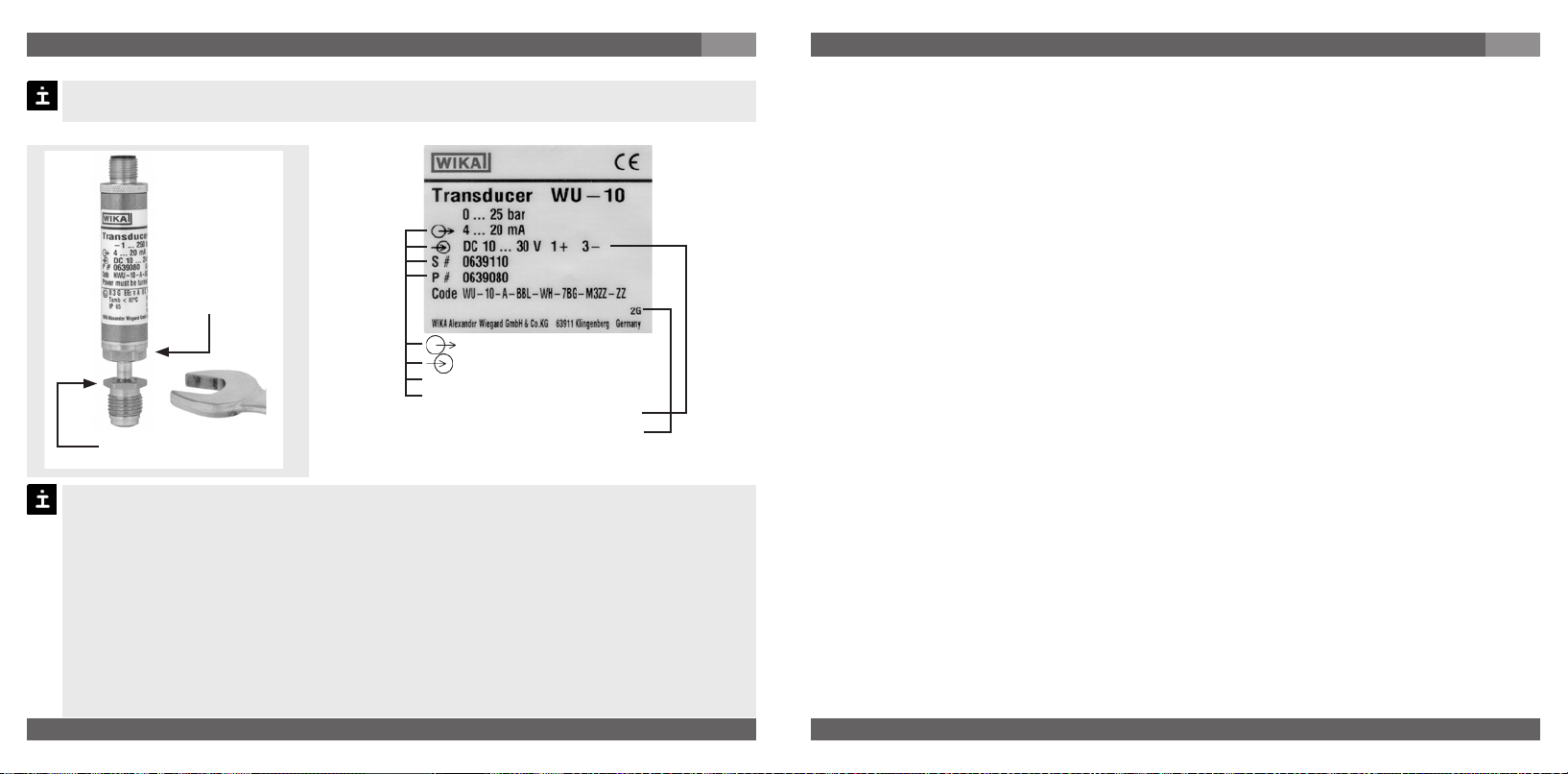
With special model number, e.g. WU-10000, WU-15000 or WU-16000, please note specifications in the delivery note.
If the serial number on the product label gets illegible (e.g. by mechanical damage or repainting), the retraceability of the instrument is not possible any more.
WIKA transducers are carefully designed and manufactured using state-of-the-art technology.
Every component undergoes strict quality and environmental inspection before assembly
and each instrument is fully tested prior to shipment. Our environmental management system
is certified to DIN EN ISO 14001. The finished instrument was tested, cleaned and carefully
packaged in a protective atmosphere prior to shipment.
Use of the product in accordance with the intended use WU-1X:
Use the transducer to transform the pressure into an electrical signal.
Knowledge required: Install and start the transducer only if you are familiar with the relevant
regulations and directives of your country and if you have the qualification required. You have
to be acquainted with the rules and regulations on hazardous areas, measurement and control
technology and electric circuits, since this transducer is „electrical equipment“ as defined by
EN 50178. Depending on the operating conditions of your application you have to have the
corresponding knowledge, e.g. of aggressive media.
2. A quick overview for you
If you want to get a quick overview, read Chapters 3, 5, 7 and 11. There you will get some
short safety instructions and important information on your product and its starting. Read
these chapters in any case.
WIKA Operating instructions/Betriebsanleitung/Mode d'emploi/Instrucciones de servicio WU-1X
2460160.06 GB/D/F/E 01/2010
2460160.06 GB/D/F/E 01/2010
3
Page 3

3. Signs, symbols and abbreviations / 4. Function / 5. For your safety
GB
3. Signs, symbols and abbreviations
The product complies with the applicable European directives.
!
Warning
Warning
Caution
Potential danger of life or of
severe injuries.
Potential danger of life or
of severe injuries due to
catapulting parts.
Potential danger of burns
due to hot surfaces.
Notice, important information, malfunction.
2-wire Two connection lines are intended
for the voltage supply.
The supply current is the measure
ment signal.
3-wire Two connection lines are intended
for the voltage supply.
One connection line is intended for
the measurement signal.
4. Function
Ultra High Purity Transducer
WU-10: Single End; WU-15: Flow Through; WU-16: Modular Surface Mount
Function: The pressure prevailing within the application is transformed into a standardised
electrical signal through the deflection of the diaphragm, which acts on the sensor element
with the power supply fed to the transmitter. This electric signal changes in proportion to the
pressure and can be evaluated correspondingly
5. For your safety
Select the appropriate transducer with regard to scale range, performance
!
Warning
dangerous media such as acetylene, flammable gases or liquids and toxic gases or liquids
and with refrigeration plants or compressors). If you do not observe the appropriate
regulations, serious injuries and/or damage can occur!
4
WIKA Operating instructions/Betriebsanleitung/Mode d'emploi/Instrucciones de servicio WU-1X
and specific measurement conditions prior to installing and starting the
instrument.
Observe the relevant national regulations (e.g.: EN 50178) and observe the
applicable standards and directives for special applications (e.g. with
5. For your safety
Open pressure connections only after the system is without pressure!
!
Warning
Configure the system with particular care when connecting up to other equipment.
Please make sure that the transducer is only used within the overload threshold limit all
the time!
Observe the ambient and working conditions outlined in section 7 „Technical data”.
Ensure that the transducer is only operated in accordance with the provisions i.e. as
described in the following instructions.
Do not interfere with or change the transducer in any other way than described in these
operating instructions.
Remove the pressure transmitter from service and mark it to prevent it from being used
again accidentally, if it becomes damaged or unsafe for operation
Have repairs performed by the manufacturer only.
The operator is responsible for the material compatibility as well as correct handling,
operation and maintenance.
The safety of the user can be detrimentally influenced by the equipment if
e.g.: - visible damage is apparent
- it cannot be operated any longer as stipulated
- it has been stored over a longer period under unsuitable conditions.
In cases of doubt the device should be returned to the manufacturers for repair and
servicing.
Information about material consistency against corrosion and diffusion can be found in our
WIKA-Handbook, 'Pressure and Temperature Measurement'.
WIKA Operating instructions/Betriebsanleitung/Mode d'emploi/Instrucciones de servicio WU-1X
2460160.06 GB/D/F/E 01/2010
2460160.06 GB/D/F/E 01/2010
Take precautions with regard to remaining media in removed pressure
transmitter. Remaining media in the pressure port may be hazardous or
toxic!
Disconnect the instrument before connecting up to the power supply.
Make sure that all parts are protected against direct contact when installing
the device and making connections.
GB
5
Page 4

6. Packaging
6. Packaging
Has everything been supplied?
Check the scope of supply:
Completely assembled transducer
Inspect the transducer for possible damage during transportation. Should there be
any obvious damage, inform the transport company and WIKA without delay.
The transducer is purified, evacuated and double-bagged for clean-room service
and should remain packaged until installation. A protective cap is used to protect the
face sealing beads from nicks or scratches. This plug should remain in place during
storage and handling, in order to prevent damage to the bead. Therefore remove the
inner ESD (Electro-Static Discharge) bag only at the place of installation.
Keep the packaging, as it offers optimal protection during transportation (e.g. chan-
ging installation location, shipment for repair).
Ensure that the pressure connection thread and the connection contacts will not be
damaged.
Remove this protection cap only just before installing the pressure transmitter
Mount the protection cap when removing and transporting the instrument.
Unpack the transducer
1. Remove the transducer from the box.
2. Remove the outer protective bag and discard.
3. Carry the transducer (sealed in the inner bag), into the clean area.
6
WIKA Operating instructions/Betriebsanleitung/Mode d'emploi/Instrucciones de servicio WU-1X
GB
7. Starting, operation
Mechanical connection
2460160.06 GB/D/F/E 01/2010
2460160.06 GB/D/F/E 01/2010
7. Starting, operation
Required tools: wrench (flats 19 and 16), screw driver (0.040" to 0.060" /
1 to 1.5 mm) and a pair of scissors, allen key for WU-16
Product label (example)
Don't use this
spanner flat!
Signal
Power Supply
Serial No.
S #
Product No.
Use this spanner flat
for screwing in!
P #
PIN assignment
Coded manufacture date
Remove the protection cap only just before installation.
When mounting the instrument, ensure that the sealing faces of the instrument and
the measuring point are clean and undamaged.
Do not scratch or nick the bead. Do not over tighten. Damage to the bead will affect
the fitting's performance and may cause leakage in the system.
Screw in or unscrew the instrument only via the flats using a suitable tool and the
prescribed torque. The appropriate torque depends on the dimension of the pressure
connection and on the sealing element used (form/material). Do not use the case as
working surface for screwing in or unscrewing the instrument.
When screwing the transmitter in, ensure that the threads are not jammed.
WIKA Operating instructions/Betriebsanleitung/Mode d'emploi/Instrucciones de servicio WU-1X
GB
7
Page 5

7. Starting, operation
GB
Mechanical Connection
Prepare the gas line connections appropriately.
You should blow clean all fitting components (such as sealing gaskets, for example) using
a clean/filtered gas. Please refer to the specific technical guides furnished by the gasket
manufacturers for additional specifications.
You can then remove the protective film, as well as any plastic caps there may be for
protecting high-quality fittings
Face Seal Connections (only WU-10, WU-15)
For connections compatible with VCR
®
-fittings:
1. Hold the swivel female face seal / swivel male face seal, mounting part (valve etc.) or case
hexagon. Tighten the swivel female face seal hand-tight and adjust the instrument to the
desired position. When tightening or untightening at mounting parts (valves etc.) or fittings,
ensure that the threads do not get jammed.
2. Hold the swivel female face seal with a suitable open-end wrench. Tighten the swivel
female face seal / swivel male face seal or mounting part (valve etc.) by a 1/8 or 1/4 turn
(depending on the sealing elements used) beyond the hand-tight position.
3. Please refer to the specific technical guides furnished by the fitting manufacturers for
additional specifications.
4. With that the transducer is mechanically connected. Electrical connection possibilities are
described in the following section.
Welding Connections (only WU-10, WU-15)
The weld needs to be fully penetrating, but amperage and heat need to be minimised. We
recommend flowing Argon gas through the transducer during welding. This will help to cool
the transducer. Prior to welding tubing to the transducer, it is recommended that a few test
welds be made.
Make sure the transducer is not wired into any other device, prior to arc
!
Warning
welding.
Disconnect the transducer from any electrical device.
Vermeiden Sie es strikt, dass Zuleitungen aus der Anschlusslitze mit
Metalloberflächen in Berührung kommen.
8
WIKA Operating instructions/Betriebsanleitung/Mode d'emploi/Instrucciones de servicio WU-1X
7. Starting, operation
Post-processing
1. Adjust the zero point (please refer to chapter Zero Adjustment).
2. Verify integrity of the weld or seal by appropriate helium leak-testing procedures.
3. Turn the gas flow ON then OFF, 10 times to remove any particles generated during
installation. (The flow rate used should at least equal the process flow specifications.)
MSM, Modular Surface Mount (only WU-16)
Please observe the corresponding technical specifications, such as torques and mounting
position of the contact components.
Electrical connection
Connect the instrument to earth via the pressure connection.
Operate the pressure transmitter with a shielded cable and earth the shield at least on
one side of the cable, if the cable is longer than 30m (2-wire) or 3m (3- or 4-wire), or if
it is run outside of the building.
Use power supplies which guarantee reliable electrical isolation of the operating
voltage as per IEC/DIN EN 60204-1. Consider also the general requirements for PELV
circuits in accordance with IEC/DIN EN 60204-1.
Ingress protection per IEC 60529 (The ingress protection classes specified only apply
while the pressure transmitter is connected with female connectors that provide the
corresponding ingress protection).
Ensure that the cable diameter you select fits to the cable gland of the connector
Ensure that the cable gland of the mounted connector is positioned correctly and
that the sealings are available and undamaged. Tighten the threaded connection and
check the correct position of the sealings in order to ensure the ingress protection.
Please make sure that the ends of cables with flying leads do not allow any ingress of
moisture.
The transducer must be connected and operated in accordance with the approriate
regulations. Take care to ensure that the electrical connection (e.g. M12 connector) is
correctly made (fully sealed).
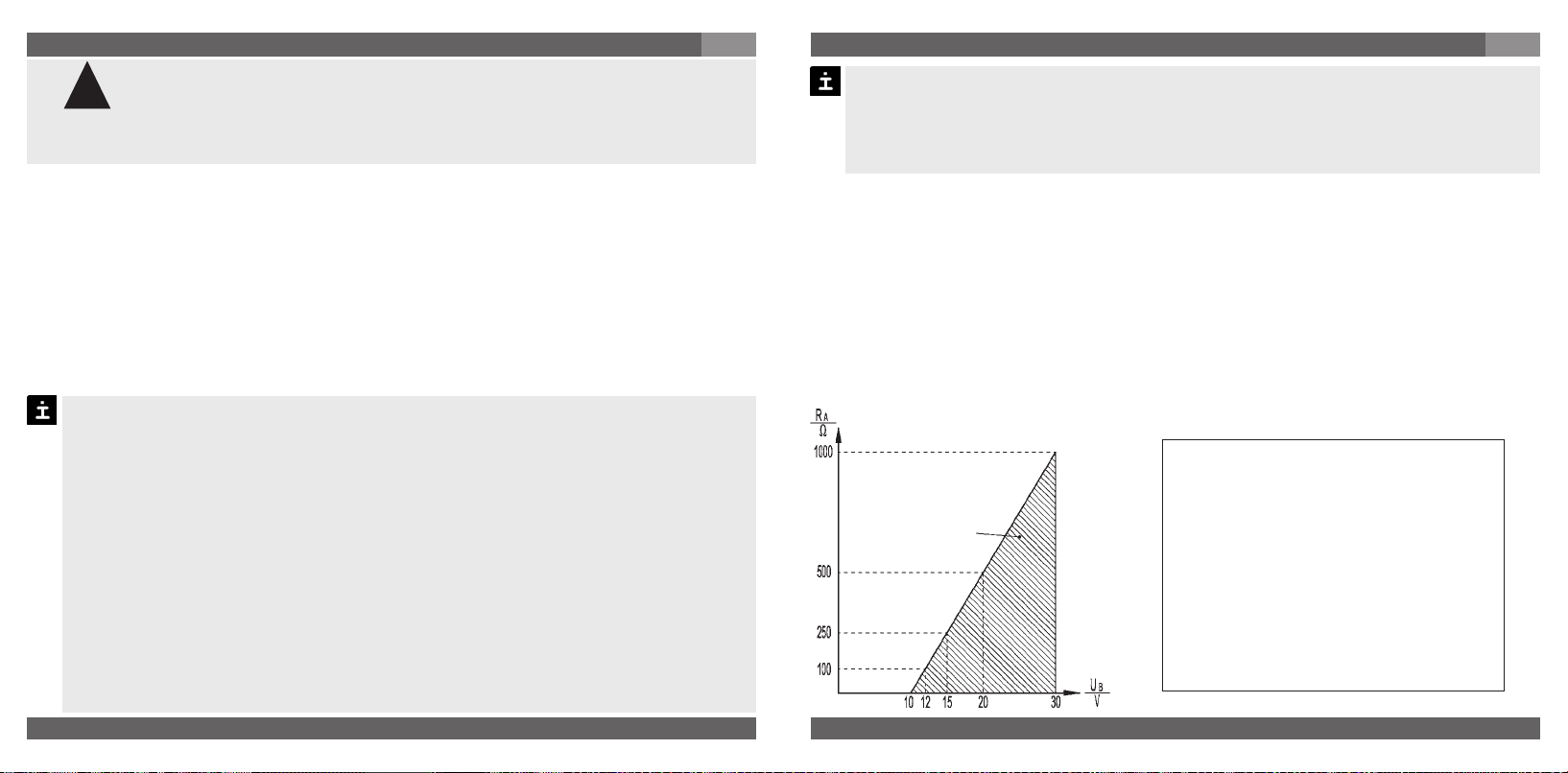
The WIKA WU Series transducer is designed to operate with an input voltage of
10 VDC < U
The interrelationship between voltage supply and load resistor (R
B ≤ 30 V (14 ... 30 V with output signal 0.1 ... 10.1 V and 0 ... 10 V).
A) is illustrated by the
following diagram.
WIKA Operating instructions/Betriebsanleitung/Mode d'emploi/Instrucciones de servicio WU-1X
2460160.06 GB/D/F/E 01/2010
2460160.06 GB/D/F/E 01/2010
GB
9
Page 6

7. Starting, operation
GB
Signal output and allowed load
4 ... 20 mA, 2-wire
Current output (2-wire)
4 ... 20 mA:
R
A ≤ (UB – 10 V) / 0,02 A
A in Ohm and UB in Volt
permitted
range
with R
Voltage output (3-wire)
0.1 ... 5.1 V:
0.1 ... 10.1 V:
1 ... 5 V:
0 ... 5 V:
0 ... 10 V:
with R
RA > 5 kOhm
RA > 10 kOhm
RA > 5 kOhm
RA > 5 kOhm
RA > 10 kOhm
A in Ohm and UB in Volt
Current for external display- or evaluation equipment can be supplied directly from the circuit,
when operating a transducer with current output. A voltage drop specific to the display unit is
to be considered. The UHP-display unit of type WUR-1 has a specific voltage drop of 6 V. The
transducers are short-circuit-proof for a short time, but anyhow any incorrect connection of
the instrument should be avoided.
Power supply
Load (e.g. display)
UB+/Sig+ Positive supply / measurement connection
OV/Sig- Negative supply / measurement connection
2-wire 3-wire
Circular connector
M 12x1, 4-pin
IP 65 (NEMA 4) *
Order code: M4
)
7. Starting, operation
Flying leads with 1.5 m of cable,
conducter cross section up to
max. 0.22 mm ², AWG 24
with end splices, conducter outer
diameter 4.8 mm
IP 65 - Order code: DI
Bayonet connector
4-pin
IP 65 (NEMA 4) *
Order code: O4
SUB D connector
15-pin
IP 54 (NEMA 3S)
Order code: TX
Circular connector R03
6-pin
IP 54 (NEMA 3S)
Order code: U6
)
2-wire
red
black
GB
3-wire
red
brown
black
10
WIKA Operating instructions/Betriebsanleitung/Mode d'emploi/Instrucciones de servicio WU-1X
)
mit Side-Access IP 54 (NEMA 3S)
*
WIKA Operating instructions/Betriebsanleitung/Mode d'emploi/Instrucciones de servicio WU-1X
2460160.06 GB/D/F/E 01/2010
2460160.06 GB/D/F/E 01/2010
11
Page 7

7. Starting, operation
GB
Specifications Model WU-1X
WU-10 / WU-15
WU-16
Pressure ranges bar 4 7 10 16 25 40 60 100 160 250 400
Over pressure safety
Burst pressure
1)
1)
Measuring principle Metal thin-film sensor
Materials
Wetted parts 2.4711 Elgiloy
Case Stainless steel
Surface finish Electropolished, typical
Dead volume WU-10 < 1500, WU-15 < 1000, WU-16 < 1000
Permissible Medium Liquid / Gas / Vapour
Power supply U
B UB in VDC
Capacitive load µF Max. 0.1 (Voltage output)
Max. current output mA < 1 Voltage output; Source
Adjustability zero % of span ± 5 via potentiometer
Response time (10 ... 90 %) ms
Dielectric strength VDC 500
Accuracy % of span
12
WIKA Operating instructions/Betriebsanleitung/Mode d'emploi/Instrucciones de servicio WU-1X
psi 60 100 160 250 300 500 1000 1500 2000 3000 5000
bar 8 14 20 32 50 80 120 200 320 500 500
bar 40 70 100 160 250 400 550 720 720 720 720
Other pressure ranges and pressure units (e.g. MPa, kg/cm
1)
1 bar = 14.50 psi
®
(Sensor); 316L VIM/VAR (Pressure connection)
2
) on request
Ra ≤ 0.18 µm (RA 7); Ra max ≤ 0.25 µm (RA 10)
B ≤ 30 (14 ... 30 V with output signal 0.1 ... 10.1 V and 0...10 V)
10 < U
mA < 30 Current output
≤
2
≤
0.25 for pressure ranges > 4 bar (BFSL)
% of span
% of span
% of span
≤
0.5 for pressure ranges ≤ 4 bar (BFSL)
2)
≤
0.5
for pressure ranges > 4 bar
2)
≤
1.0
for pressure ranges ≤ 4 bar
7. Starting, operation
Specifications Model WU-1X
2)
Including non-linearity, hysteresis, zero point and full scale error (corresponds to
error of measurement per IEC 61298-2).
Adjusted in vertical mounting position with lower pressure connection.
Non-linearity % of span
% of span
1-year stability % of span
Permissible temperature of
Medium -40 ... +100 °C -40 ... +212 °F
Ambience -20 ... +85 °C -4 ... +185 °F
Storage -40 ... +100 °C -40 ... +212 °F
Compensated temp range -20 ... +80 °C -4 ... +176 °F
Temperature coefficients within
compensated temp range
Mean TC of zero % of span
Mean TC of range % of span
CE- conformitiy
Pressure equipment directive 97/23/EC
EMC directive
Directive ATEX of equipment
intended for use in potentially
explosive atmospheres
Shock resistance g 500 according to IEC 60068-2-27 (mechanical shock)
Vibration resistance g 10 according to IEC 60068-2-6 (vibration under resonance)
Wiring protection
Short-circuit proofness Sig+ towards U
Reverse polarity protection U
Weight kg Approx. 0.1
WIKA Operating instructions/Betriebsanleitung/Mode d'emploi/Instrucciones de servicio WU-1X
2460160.06 GB/D/F/E 01/2010
2460160.06 GB/D/F/E 01/2010
0.15 for pressure ranges > 4 bar (BFSL) according to IEC 61298-2
≤
≤
0.3 for pressure ranges ≤ 4 bar (BFSL) according to IEC 61298-2
≤
0.2 (at reference conditions)
≤
0.1 / 10 K
≤
0.15 / 10 K
2004/108/EC, EN 61 326 Emission (Group 1, Class B) and
Immunity (industrial locations)
94/9/EC
B- (short-time)
B+ towards UB-
GB
13
Page 8

7. Starting, operation / 8. Adjustment of zero point
GB
For version FM-Approved please note the special connection conditions on the enclosed
control drawing.
When designing your plant, take into account that the stated values (e.g.burst pressure,
over pressure safety) apply depending on the material, thread and sealing element used.
Functional test
The output signal must be proportional to the pressure. If not, this might point to a
damage of the diaphragm. In that case refer to chapter 10 „Troubleshooting“.
Open pressure connections only after the system is without pressure!
Observe the ambient and working conditions outlined in section 7
Warning
„Technical data.
Please make sure that the transducer is only used within the over load
threshold limit at all times!
When touching the transducer, keep in mind that the surfaces of the instru-
ment components might get hot during operation.
Caution
8. Adjustment of zero point
These Transducers are maintenance free.
If a zero offset occurs anyhow, this can be adjusted by means of a built-in potentiometer.
For verification and adjustment of the zero point, vent the transducer to zero (0)PSI for gage
reference transducers. The potentiometer for the zero adjustment is protected inside the transducer housing. Use a 0.040" to 0.060" (1 to 1.5 mm) jeweler's screwdriver for adjustment.
Span adjustment is not necessary after zero point correction.
14
WIKA Operating instructions/Betriebsanleitung/Mode d'emploi/Instrucciones de servicio WU-1X
8. Adjustment of zero point
Procedure for Transducer without Side-Access
1. Remove all power to the transducer.
2. Remove the locking ring, on the top of transducer, in order to expose
the zero adjusting potentiometer. Carefully pull the assembly out of the
transducer housing, as far as the internal connector cable will allow.
3. Restore power to the transducer.
4. Vent the transducer to pressureless state. Monitor the output signal,
and adjust the zero screw to 4mA or 0.1V depending on the signal
output. The Zero adjustment screws are both turned in a clockwise
direction to increase the signal or in a counter clock-wise direction to
decrease the signal.
5. Remove all power to the transducer again.
6. Rotate the electrical connector on the transducer housing to
the keyed insertion. After this, replace and hand tighten the
locking ring on the top of transducer.
Procedure for Transducer with Side-Access
1. Turn the grip ring until the access to the
potentiometer is free.
2. Adjust the zero point by means of the
potentiometer in pressureless state.
When doing this, do not contact other
components with the screw driver to
excluse a short circuit in the instrument.
Check the zero point by means of a
suitable instrument. Clockwise rotation
means an upward zero offset,
anti-clockwise rotation means a down
ward zero offset.
3. After this, turn the grip screw until the
access to the potentiometer is closed
For further information
(+49) 9372/132-295
again.
WIKA Operating instructions/Betriebsanleitung/Mode d'emploi/Instrucciones de servicio WU-1X
2460160.06 GB/D/F/E 01/2010
2460160.06 GB/D/F/E 01/2010
GB
15
Page 9

9. Maintenance, accessories
GB
9. Maintenance, accessories
WIKA transducers require no maintenance.
Have repairs performed by the manufacturer only.
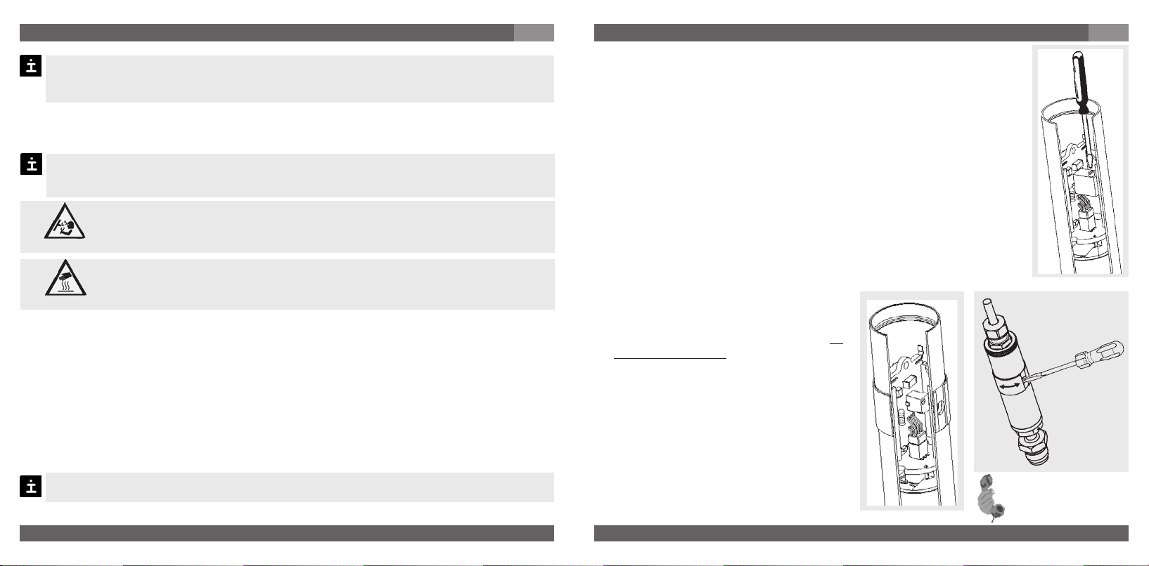
Board Replacement
For board replacement, vent the transducer to pressureless state.
Remove all power to the transducer.
Protect the transducer from voltage, or static discharge, to prevent possible damage.
Disassembly
1. Protect the PCB and other electrical
devices from voltage, or static discharge,
to prevent possible damage. Ensure you
have a ground strap attached to your body.
2. Remove the locking ring, on the top of
transducer.
3. Carefully pull the assembly out of the
transducer housing, as far as the internal
con-nector cable will allow. Remove the
4-pin connector from the universal
electron-ics board assembly.
4. Hang the tool supplied with the replacement
PCB into the bore of the PCB.
5. While firmly holding the transducer body,
pull the PCB straight out of the
transducer body assembly.
Reassembly
1. Firmly push the new PCB into the transducer body as far as it will go.
2. Align the pins on the connector from the electrical connector with the sockets on the new
universal electronics board assembly.
3. Rotate the electrical connector on the transducer housing to the keyed insertion.
Replace and hand tighten the locking ring, on the top of transducer.
16
WIKA Operating instructions/Betriebsanleitung/Mode d'emploi/Instrucciones de servicio WU-1X
without side-access
with side-access
9. Maintenance, accessories / 10. Trouble shooting
Accessories: For details about the accessories (e. g. connectors), please refer to WIKA‘s
price list, WIKA‘s product catalog on CD or or contact our sales department.
10. Trouble shooting
Open pressure connections only after the system is without pressure!
Warning
Take precautions with regard to remaining media in removed transducers.
!
Warning
Do not insert any pointed or hard objects into the pressure port for cleaning to prevent
damage to the diaphragm of the pressure connection.
Please verify in advance if pressure is being applied (valves/ ball valve etc. open) and if the
right voltage supply and the right type of wiring (2-wire/3-wire) has been chosen?
Failure Possible cause Procedure
Output signal unchanged after change
in pressure
No output signal
No/False output signal
Abnormal output signal or
Abnormal zero point signal
WIKA Operating instructions/Betriebsanleitung/Mode d'emploi/Instrucciones de servicio WU-1X
2460160.06 GB/D/F/E 01/2010
2460160.06 GB/D/F/E 01/2010
Remaining media in the pressure port may be hazardous or toxic!
Remove the transducer from service and mark it to prevent it from being
used again accidentally, if it becomes damaged or unsafe for operation.
Have repairs performed by the manufacturer only.
Mechanical overload through overpressure
Wrong supply voltage or current spike Replace instrument
No/incorrect voltage supply or current
spike
Cable break Check connections and cable
Incorrectly wired (e.g. Connected as
2-wire instead of 3-wire system)
Zero point set wrongly
Replace instrument; if failure reoccurs,
consult the manufacturer *)
Adjust the voltage supply to correspond
with the Operating Instructions *)
Follow pin assignment (see Instrument
Label / Operating Instructions)
Adjust zero point correctly (see chapter
8); a sufficiently accurate current/volt
meter should be used
GB
17
Page 10

10. Trouble shooting
GB
Failure Possible cause Procedure
Abnormal zero point signal
Signal span dropping off/too small
Signal span too small Power supply too high/too low
In case of unjustified reclamation we charge the reclamation handling expenses.
*) Make sure that after the setting the unit is working properly. In case the error continues to exist send in the instrument for
reparation (or replace the unit).
Medium or ambient temperature too
high/too low
Diaphragm is damaged, e.g. through
impact, abrasive/agressive media;
corrosion of diaphragm/pressure
connector.
Diaphragm is damaged, e.g. through
impact, abrasive/agressive media;
corrosion of diaphragm/pressure
connector
Mechanical overload through overpressure
Control the internal temperature of the
instrument within the permissible range;
observe the allowable temperature error
(see Operating Instructions)
Replace instrument
Contact the manufacturer and replace
the instrument
Correct the power supply in line with
the Operating Instructions
Re-calibrate the instrument *)
If the problem persists, contact our sales department.
USA, Canada: If the problem continues, contact WIKA or an authorized agent for assistance.
If the pressure transmitter must be returned obtain an RMA (return material authorization)
number and shipping instructions from the place of purchase. Be sure to include detailed
information about the problem. Pressure transmitters received by WIKA without a valid RMA
number will not be accepted.
Process material certificate (Contamination declaration for returned goods)
Purge / clean dismounted instruments before returning them in order to protect our
employees and the environment from any hazard caused by adherent remaining media.
Service of instruments can only take place safely when a Product Return Form has been
submitted and fully filled-in. This Return Form contains information on all materials with
which the instrument has come into contact, either through installation, test purposes,
or cleaning. You can find the Product Return Form on our internet site (www.wika.de).
18
WIKA Operating instructions/Betriebsanleitung/Mode d'emploi/Instrucciones de servicio WU-1X
11. Storage, disposal
11. Storage, disposal
When storing or disposing of the transducer, take precautions with regard
!
Warning
Storage
Mount the protection cap when storing the transducer.
Disposal
Dispose of instrument components and packaging materials in accordance with the
respective waste treatment and disposal regulations of the region or country to which
the instrument is supplied.
WIKA reserves the right to alter these technical specifications.
WIKA Operating instructions/Betriebsanleitung/Mode d'emploi/Instrucciones de servicio WU-1X
2460160.06 GB/D/F/E 01/2010
2460160.06 GB/D/F/E 01/2010
to remaining media in removed transducers. We recommend cleaning the
transducer properly and carefully. Remaining media in the pressure port
may be hazardous or toxic!
GB
19
Page 11

1. Wichiges zu Ihrer Information / 2. Der schnelle Überblick für Sie
D
1. Wichtiges zu Ihrer Information
Lesen Sie diese Betriebsanleitung vor Montage und Inbetriebnahme des Druckmessgerätes.
Bewahren Sie die Betriebsanleitung an einem für alle Benutzer jederzeit zugänglichen Ort auf.
Die nachfolgenden Einbau- und Betriebshinweise haben wir mit Sorgfalt zusammengestellt.
Es ist jedoch nicht möglich, alle erdenklichen Anwendungsfälle zu berücksichtigen. Sollten Sie
Hinweise für Ihre spezielle Aufgabenstellung vermissen, können Sie hier weitere Informationen
finden:
Über unsere Internet-Adresse www.wika.de / www.wika.com
Die Bezeichnung des zugehörigen Datenblattes ist PE 87.05
Anwendungsberater: (+49) 9372/132-295
Bei Sondertypennummer, z.B. WU-10000, WU-15000 oder WU-16000, beachten Sie die
Spezifikationen gemäß Lieferschein. Wird die Seriennummer auf dem Typenschild unleserlich
(z. B. durch mechanische Beschädigung oder Übermalen), ist eine Rückverfolgbarkeit nicht
mehr möglich. Die in der Betriebsanleitung beschriebenen WIKA-Transducer werden nach den
neuesten Erkenntnissen konstruiert und gefertigt. Alle Komponenten unterliegen während der
Fertigung strengen Qualitäts- und Umweltkriterien. Unser Umweltmanagementsystem ist nach
DIN EN ISO 14001 zertifiziert. Das fertige Gerät wurde vor dem Versand getestet, gereinigt und
sorgfältig unter Schutzatmosphäre verpackt.
Bestimmungsgemäße Produktverwendung WU-1X:
Verwenden Sie den Transducer, um Druck in ein elektrisches Signal zu wandeln.
Ihre erforderlichen Kenntnisse
Montieren und nehmen Sie den Transducer nur in Betrieb, wenn Sie mit den zutreffenden
landesspezifischen Richtlinien vertraut sind und die entsprechende Qualifikation besitzen. Sie
müssen mit den Vorschriften und Kenntnissen für explosionsgefährdete Bereiche, Mess- und
Regeltechnik sowie elektrische Stromkreise vertraut sein, da der Transducer ein „elektrisches
Betriebsmittel“ nach EN 50178 ist. Je nach Einsatzbedingung müssen Sie über entsprechendes Wissen verfügen, z. B. über agressive Medien.
2. Der schnelle Überblick für Sie
Wollen Sie sich einen schnellen Überblick verschaffen, lesen Sie Kapitel 3, 5, 7 und 11. Dort
erhalten Sie kurze Hinweise zu Ihrer Sicherheit und wichtige Informationen über Ihr Produkt
und zur Inbetriebnahme. Lesen Sie diese unbedingt.
20
WIKA Operating instructions/Betriebsanleitung/Mode d'emploi/Instrucciones de servicio WU-1X
3. Zeichenerklärungen, Abkürzungen / 4. Funktion / 5. Zu Ihrer Sicherheit
3. Zeichenerklärungen, Abkürzungen
!
Warnung
Warnung
Vorsicht
Mögliche Gefahr für Ihr
Leben oder schwerer
Verletzungen.
Mögliche Gefahr für Ihr
Leben oder schwerer Verletzungen durch wegschleudernde Teile.
Mögliche Gefahr von
Verbrennungen durch
heisse Oberflächen.
Hinweis, wichtige Information, Funktionsstörung.
2-Leiter Zwei Anschlussleitungen dienen zur
Spannungsversorgung.
Der Speisestrom ist das Mess Signal.
3-Leiter Zwei Anschlussleitungen dienen zur
Spannungsversorgung.
Eine Anschlussleitung dient für das
Mess-Signal
Das Produkt stimmt mit den
zutreffenden europäischen Richtlinien überein.
4. Funktion
Ultra High Purity Transducer
WU-10: Single End; WU-15: Flow Through; WU-16: Modular Surface Mount
Funktion: Mittels Sensorelement und unter Zuführung von Hilfsenergie wird über die Verfor-
mung einer Membran der anstehende Druck in Ihrer Anwendung in ein verstärktes standardisiertes elektrisches Signal umgewandelt. Dieses elektrische Signal verändert sich proportional
zum Druck und kann entsprechend ausgewertet werden.
5. Zu Ihrer Sicherheit
Wählen Sie den richtigen Transducer hinsichtlich Messbereich, Ausführung
!
Warnung
Normen und Richtlinien (z. B. bei gefährlichen Messstoffen wie Acetylen, brennbaren
oder giftigen Stoffen sowie bei Kälteanlagen und Kompressoren). Wenn Sie die entspre-
chenden Vorschriften nicht beachten, können schwere Körperverletzungen und
Sachschäden entstehen!
WIKA Operating instructions/Betriebsanleitung/Mode d'emploi/Instrucciones de servicio WU-1X
2460160.06 GB/D/F/E 01/2010
2460160.06 GB/D/F/E 01/2010
und spezifischen Messbedingungen vor Montage oder Inbetriebnahme.
Halten Sie die entsprechenden landesspezifischen Vorschriften ein (z. B.:
EN 50178) und beachten Sie bei speziellen Anwendungen die geltenden
D
21
Page 12

5. Zu Ihrer Sicherheit / 6. Verpackung
Öffnen Sie Anschlüsse nur im drucklosen Zustand!
!
Warnung
Trennen Sie das Gerät vor dem Öffnen von der Versorgungsspannung.
Achten Sie bei der Montage darauf, dass alle Teile gegen direktes Berühren geschützt
sind.
Konzipieren Sie die Beschaltung besonders sorgfältig beim Anschluss an andere Geräte.
Betreiben Sie den Transducer immer innerhalb des Überlastgrenzbereiches!
Beachten Sie die Betriebsparameter gemäß Punkt 7 „Technische Daten“.
Stellen Sie sicher, dass der Transducer nur bestimmungsgemäß -also wie in der folgenden
Anleitung beschrieben- betrieben wird.
Unterlassen Sie unzulässige Eingriffe und Änderungen am Transducer, welche nicht in
dieser Betriebsanleitung beschrieben sind.
Setzen Sie den Transducer außer Betrieb und schützen Sie ihn gegen versehentliche Inbe-
triebnahme, wenn Sie Störungen nicht beseitigen können.
Lassen Sie Reparaturen nur vom Hersteller durchführen.
Der Anwender ist für die Materialverträglichkeit sowie die vorschriftsmäßige Handhabung,
Betrieb und Wartung verantwortlich.
Die Sicherheit des Benutzers kann durch das Gerät beeinträchtigt sein, wenn es
z.B.:-sichtbareSchädenaufweist
-nichtmehrwievorgeschriebenarbeitet
-längereZeitunterungeeignetenBedingungengelagertwurde
In Zweifelsfällen sollten Sie das Gerät grundsätzlich an den Hersteller zur Überprüfung
einschicken.
Angaben zu Korrosions- bzw. Diffusionsbeständigkeit der Gerätewerkstoffe entnehmen Sie
bitte unserem WIKA-Handbuch zur Druck- und Temperaturmesstechnik.
Ergreifen Sie Vorsichtsmaßnahmen für Messstoffreste in ausgebauten
Transducern. Messstoffreste können zur Gefährdung von Menschen,
Umwelt und Einrichtung führen!
6. Verpackung
Wurde alles geliefert?
Überprüfen Sie den Lieferumfang:
Komplett montierte Transducer
22
WIKA Operating instructions/Betriebsanleitung/Mode d'emploi/Instrucciones de servicio WU-1X
D
6. Verpackung / 7. Inbetriebnahme, Betrieb
Entpacken der Geräte
1. Nehmen Sie den Transducer aus dem Karton.
2. Entfernen Sie danach vorsichtig die erste durchsichtige Folie ohne die ESD-Schutzfolie zu
beschädigen.
3. Bringen Sie das Gerät inkl. ungeöffneter ESD-Schutzfolie in den Reinraum.
WIKA Operating instructions/Betriebsanleitung/Mode d'emploi/Instrucciones de servicio WU-1X
2460160.06 GB/D/F/E 01/2010
2460160.06 GB/D/F/E 01/2010
D
Untersuchen Sie den Transducer auf eventuell entstandene Transportschäden. Sind
offensichtlich Schäden vorhanden, teilen Sie dies dem Transportunternehmen und
WIKA unverzüglich mit.
Die UHP-Transducer wurden in Reinräumen unter Schutzatmosphäre (Reinraum-
klasse 100) gereinigt, evakuiert und doppelt verpackt. Die hochwertigen Verschraubungen (Fittings) sind mit speziellen Kunststoffkappen geschützt. Zum Schutz gegen
Beschädigung und Kontamination sollten Sie die Geräte in dieser Spezialverpackung
bis zu ihrem Einbau lassen. Entfernen Sie daher die ESD-Schutzfolie (Electro-StaticDischarge) erst am Einsatzort.
Bewahren Sie die Verpackung auf, denn diese bietet bei einem Transport einen opti-
malen Schutz (z. B. wechselnder Einbauort, Reparatursendung).
Achten sie darauf, dass das Druckanschluss-Gewinde und die Anschlusskontakte
nicht beschädigt werden.
Entfernen Sie die Schutzkappe erst kurz vor dem Einbau.
Montieren Sie die Schutzkappe bei Ausbau und Transport des Gerätes.
23
Page 13

7. Inbetriebnahme, Betrieb
7. Inbetriebnahme, Betrieb
Benötigtes Werkzeug: Maulschlüssel SW 19 und 16, Schraubendreher der Größe 1 bis
1,5 mm, Schere, Inbusschlüsselsatz für WU-16
Montage mechanischer Anschluss
Benutzen Sie
nicht diese
Schlüsselfläche!
Benutzen Sie diese
Schlüsselfläche zum
Einschrauben!
Entfernen Sie die Schutzkappe erst kurz vor dem Einbau.
Achten Sie bei der Montage auf saubere und unbeschädigte Dichtflächen am Gerät
und Messstelle.
Zerkratzen Sie nicht die Dichtlippen. Ein übermäßiges Anziehen kann die Dichtlippen
beschädigen und zu möglichen Leckagen führen.
Schrauben Sie das Gerät nur über die Schlüsselflächen mit einem geeigneten Werk-
zeug und dem vorgeschriebenen Drehmoment ein bzw. aus. Das richtige Drehmoment ist abhängig von der Dimension des Druckanschlusses sowie der verwendeten
Dichtung (Form/Werkstoff). Verwenden Sie zum Ein- bzw. Ausschrauben nicht das
Gehäuse als Angriffsfläche.
Beachten Sie beim Einschrauben, dass die Gewindegänge nicht verkantet werden.
24
WIKA Operating instructions/Betriebsanleitung/Mode d'emploi/Instrucciones de servicio WU-1X
Typenschild (Beispiel)
Signal
Spannungsversorgung
Serien-Nr.
S #
P #
Erzeugnis-Nr.
Anschlussbelegung
Codiertes Herstelldatum
D
7. Inbetriebnahme, Betrieb
Mechanischer Anschluss
Verschraubungen (nur WU-10 / WU-15)
Für Verschraubungen (Fittings) mit Innen- bzw. Außengewinde kompatibel zu VCR
Anschlüssen gilt:
1. Halten Sie die Überwurfmutter/Druckschraube oder Armatur bzw. den Gehäusesechskant
fest. Ziehen Sie die Überwurfmutter handfest an und richten das Sie Gerät in die gewünsch
te Position aus. Beachten Sie beim Ein- bzw. Aufschrauben an Armaturen oder Fittings,
dass die Gewindegänge nicht verkantet werden.
2. Halten Sie die Überwurfmutter mit einem geeigneten Maulschlüssel fest. Ziehen Sie
die Überwurfmutter/Druckschraube oder Armatur mit einer 1/8 bzw. 1/4 Drehung (abhängig
von den verwendeten Dichtungen) über die handfeste Stellung hinaus an.
3. Bitte beachten Sie auch die entsprechenden technischen Spezifikationen und Hinweise
der spezifischen Anschlusshersteller (Glands + Fittings).
4. Der Transducer ist damit mechanisch angeschlossen. Elektrische Anschlussmöglichkeiten
werden im folgenden Abschnitt behandelt.
WIKA Operating instructions/Betriebsanleitung/Mode d'emploi/Instrucciones de servicio WU-1X
2460160.06 GB/D/F/E 01/2010
2460160.06 GB/D/F/E 01/2010
D
Bereiten Sie die Anschlüsse der Gasleitungen entsprechend vor.
Sie sollten alle Anschlusskomponenten wie z.B. Dichtscheiben mit einem reinen/gefilterten
Gas reinigen. Beachten Sie hierbei die entsprechenden Einbauvorschriften der
verwendeten herstellerspezifischen Dichtscheiben.
Die Schutzfolie sowie evtl. vorhandene Kunststoffkappen zum Schutz der hochwertigen
Anschlüsse können Sie jetzt entfernen.
®
25
Page 14

7. Inbetriebnahme, Betrieb
D
Schweißanschlüsse (nur WU-10 / WU-15)
Die Schweißnaht muss vollständig und durchgängig geschweißt sein. Achten Sie dennoch auf
minimalen Strom und Hitzeeintrag gegenüber den Geräten. Zum Kühlen empfehlen wir den
Durchfluss von Argon während des Schweißprozesses. Es empfiehlt sich, vor dem eigentlichen Schweißen der Transducer einige Testschweißungen durchzuführen.
Stellen Sie vor dem Lichtbogenschweißen sicher, dass der Transducer an
!
Warnung
keine weiteren Geräte angeschlossen ist.
Trennen Sie alle elektrischen Anschlüsse mit dem Transducer.
Vermeiden Sie es strikt, dass Zuleitungen aus der Anschlusslitze mit
Metalloberflächen in Berührung kommen.
Nachbearbeitung
1. Der Nullpunkt ist unter Umständen abzugleichen (siehe Punkt Nullpunktabgleich).
2. Prüfen Sie alle mechanischen Anschlüsse (Fittings, Schweißungen) mittels geeignetem Test
(z.B. Helium Leak Test) auf Dichtigkeit.
3. Der Gasdurchfluss sollten Sie mindestens 10-mal ein und wieder ausschalte, um eventuell
bei der Installation eingedrungene Partikel zu entfernen. Die Durchflussrate des Gases
sollte hierbei dem späteren Prozessfluss entsprechen.
MSM-Anschlüsse (nur WU-16)
Bitte beachten Sie die entsprechenden technischen Spezifikationen wie Drehmomente und
Einbauposition der Anschlusskomponenten.
Montage elektrischer Anschluss
Erden Sie das Gerät über den Druckanschluss.
Betreiben Sie den Druckmessumformer mit geschirmter Leitung und erden Sie den
Schirm auf mindestens einer Leitungsseite, wenn die Leitungen länger als 30m (2Leiter) bzw. 3m (3- bzw. 4-Leiter) sind oder das Gebäude verlassen.
Verwenden Sie ausschließlich Stromquellen, die eine sichere elektrische Trennung
der Betriebsspannung nach IEC/DIN EN 60204-1 gewährleisten. Berücksichtigen Sie
zusätzlich die allgemeinen Anforderungen an PELV-Stromkreise gemäß
IEC/DIN EN 60204-1.
Schutzart IP nach IEC 60 529 (Die angegebenen Schutzarten gelten nur im gesteckten
Zustand mit Leitungsteckern (Buchsen) entsprechender Schutzart).
26
WIKA Operating instructions/Betriebsanleitung/Mode d'emploi/Instrucciones de servicio WU-1X
7. Inbetriebnahme, Betrieb
Wählen Sie den Kabeldurchmesser passend zur Kabeldurchführung des Steckers.
Achten Sie darauf, dass die Kabelverschraubung des montierten Steckers korrekt
sitzt und dass die Dichtungen vorhanden und nicht beschädigt sind. Ziehen Sie die
Verschraubung fest und überprüfen Sie den korrekten Sitz der Dichtungen, um die
Schutzart zu gewährleisten.
Stellen Sie bei Kabelausgängen sicher, dass am Ende des Kabels keine Feuchtigkeit
eintritt.
Der Transducer muss bestimmungsgemäß angeschlossen und betrieben werden.
Achten Sie auf den korrekten (dichten) Verschluss der elektrischen Verbindung (z.B.
M12-Kupplung).
Der elektrische Anschluss der Transducer wird über Stecker oder Kabel hergestellt.
Als Hilfsenergie genügt eine Gleichspannung innerhalb der angegebenen Grenzen.
Hilfsenergie U
B: 10 VDC < U
≤ 30 V (14 ... 30 V mit Ausgangssignal 0,1 ... 10,1 V und
B
0 ... 10 V). Den Zusammenhang zwischen Spannungsversorgung und Bürdenwiderstand (R
verdeutlicht die folgende Zeichnung:
Ausgangssignal und zulässige Bürde
4 ... 20 mA, 2-Leiter
Stromausgang (2-Leiter)
4 ... 20 mA:
R
A ≤ (UB – 10 V) / 0,02 A
zulässiger
Bereich
WIKA Operating instructions/Betriebsanleitung/Mode d'emploi/Instrucciones de servicio WU-1X
2460160.06 GB/D/F/E 01/2010
2460160.06 GB/D/F/E 01/2010
Spannungsausgang (3-Leiter)
0,1 ... 5,1 V:
0,1 ... 10,1 V:
1 ... 5 V:
0 ... 5 V:
0 ... 10 V:
mit R
RA > 5 kOhm
RA > 10 kOhm
RA > 5 kOhm
RA > 5 kOhm
RA > 10 kOhm
A in Ohm und UB in Volt
D
D
A)
27
Page 15

7. Inbetriebnahme, Betrieb
D
7. Inbetriebnahme, Betrieb
D
Bei Transducern mit Stromausgang können externe Anzeige- und Auswertegeräte direkt aus
der Stromschleife gespeist werden. Dabei ist ein, durch das Anzeigegerät spezifischer zusätzlicher Spannungsabfall zu beachten. Bei der UHP-Aufsteckanzeige Typ WUR-1 beträgt dieser
zusätzliche Spannungsabfall 6 V. Die Transducer sind kurzzeitig kurzschlussfest; dennoch
sollte eine falsche Beschaltung des Gerätes vermieden werden.
Spannungsversorgung
Verbraucher
UB+/Sig+ Positiver Versorgungs- / Messanschluss
OV/Sig- Negativer Versorgungs- / Messanschluss
2-Leiter 3-Leiter
Rundsteckverbinder
M 12x1, 4-polig
IP 65 (NEMA 4) *
Bestellcode: M4
Kabelausgang mit 1,5 m Länge,
Leitungsquerschnitt max.
0,22 mm ², AWG 24 mit Aderendhülsen, Leitungsaußendurchmesser 4,8 mm
IP 65 (NEMA 4)
Bestellcode: DI
)
rot
schwarz
rot
braun
schwarz
Bajonett-Rundsteckverbinder
4-polig
IP 65 (NEMA 4) *
Bestellcode: O4
SUB D Stecker
15-polig
IP 54 (NEMA 3S)
Bestellcode: TX
Rundsteckverbinder R03
6-polig
IP 54 (NEMA 3S)
Bestellcode: U6
)
*
mit Side-Access IP 54 (NEMA 3S)
)
2-Leiter
3-Leiter
28
WIKA Operating instructions/Betriebsanleitung/Mode d'emploi/Instrucciones de servicio WU-1X
WIKA Operating instructions/Betriebsanleitung/Mode d'emploi/Instrucciones de servicio WU-1X
2460160.06 GB/D/F/E 01/2010
2460160.06 GB/D/F/E 01/2010
29
Page 16

7. Inbetriebnahme, Betrieb
D
Technische Daten Typ WU-1X
WU-10 / WU-15
WU-16
Messbereich bar 4 7 10 16 25 40 60 100 160 250 400
Überlastgrenze
Berstdruck
Messprinzip Metallischer Dünnfilmsensor
Werkstoff
Messstoffberührte Teile 2.4711 Elgiloy
Gehäuse CrNi-Stahl
Oberflächengüte Elektropoliert, typ. Ra ≤ 0,18 µm (RA 7);
Totraumvolumen mm
Zulässige Messstoffe Flüssigkeiten / Gase / Nebel
Hilfsenergie U
Kapazitive Bürde µF max. 0,1 (Spannungsausgang)
Max. Ausgangsstrom mA < 1 Spannungsausgang; Source
Einstellbarkeit Nullpunkt % d. Spanne ± 5 durch Potentiometer
Einstellzeit (10 … 90 %) ms
Spannungsfestigkeit VDC 500
Genauigkeit % d. Spanne
30
1)
1)
B UB in VDC 10 < UB ≤ 30 (14 ... 30 V mit Ausgang 0,1 ... 10,1 V und 0 ... 10 V)
WIKA Operating instructions/Betriebsanleitung/Mode d'emploi/Instrucciones de servicio WU-1X
psi 60 100 160 250 300 500 1000 1500 2000 3000 5000
bar 8 14 20 32 50 80 120 200 320 500 500
bar 40 70 100 160 250 400 550 720 720 720 720
Weitere Druckbereiche und Druckeinheiten (z.B. MPa, kg/cm
1)
1 bar = 14,50 psi
®
(Sensor); 316L VIM/VAR (Druckanschluss)
3
mA < 30 Stromausgang
% d. Spanne
% d. Spanne
% d. Spanne
max. Ra ≤ 0,25 µm (RA 10)
WU-10 < 1500, WU-15 < 1000, WU-16 < 1000
≤
2
≤
0,25 für Messbereiche > 4 bar (BFSL)
≤
0,5 für Messbereiche ≤ 4 bar (BFSL)
2)
≤
0,5
für Messbereiche > 4 bar
2)
≤
1,0
für Messbereiche ≤ 4 bar
2
) auf Anfrage
7. Inbetriebnahme, Betrieb
Technische Daten Typ WU-1X
2)
Einschließlich Nichtlinearität, Hysterese, Nullpunkt- und Endwertabweichung
(entspricht Messabweichung nach IEC 61298-2).
Kalibriert bei senkrechter Einbaulage Druckanschluss nach unten.
Nichtlinearität % d. Spanne
% d. Spanne
Stabilität pro Jahr % d. Spanne
Zulässige Temperaturbereiche
Messstoff °C -40 ... +100
Umgebung °C -20 ... +85
Lagerung °C -40 ... +100
Kompensierter Temperaturbereich °C -20 ... +80
Temperaturkoeffizienten im
kompensierten Temperaturbereich
Mittlerer TK des Nullpunktes % d. Spanne
Mittlerer TK der Spanne % d. Spanne
CE- Kennzeichen
Druckgeräterichtlinie 97/23/EG
EMV-Richtlinie
Schockbelastbarkeit g 500 nach IEC 60068-2-27 (Schock mechanisch)
Vibrationsbelastbarkeit g 10 nach IEC 60068-2-6 (Vibration bei Resonanz)
Elektrische Schutzarten
Kurzschlussfestigkeit Sig+ gegen UB- (kurzzeitig)
Verpolschutz UB+ gegen UB-
Gewicht kg Ca. 0,1
0,15 für Messbereiche > 4 bar (BFSL) nach IEC 61298-2
≤
≤
0,3 für Messbereiche ≤ 4 bar (BFSL) nach IEC 61298-2
≤
0,2 (bei Referenzbedingungen)
≤
0,1 / 10 K
≤
0,15 / 10 K
2004/108/EG, EN 61326 Emission (Gruppe 1, Klasse B) und
Störfestigkeit (industrieller Bereich)
Für die Ausführung FM Approved beachten Sie bitte die besonderen Anschlussbedingungen
in der beiliegenden Kontrollzeichnung (Control drawing).
WIKA Operating instructions/Betriebsanleitung/Mode d'emploi/Instrucciones de servicio WU-1X
2460160.06 GB/D/F/E 01/2010
2460160.06 GB/D/F/E 01/2010
D
31
Page 17
7. Inbetriebnahme, Betrieb / 8. Einstellung Nullpunkt
D
Beachten Sie bei der Auslegung Ihrer Anlage, dass die angegebenen Werte (z. B.
Berstdruck, Überlastgrenze) in Abhängigkeit vom verwendeten Material, Gewinde und
Dichtung gelten.
Funktionsprüfung
Das Ausgangssignal muss sich dem anstehenden Druck proportional verhalten. Wenn
dies nicht so ist, kann das ein Hinweis auf eine Beschädigung der Membran sein. Lesen
Sie in diesem Fall in Kapitel 10 „Störbeseitigung“ nach.
Öffnen Sie Anschlüsse nur im drucklosen Zustand!
Beachten Sie die Betriebsparameter gemäß Punkt 7 „Technische Daten“.
Warnung
Betreiben Sie den Transducer immer innerhalb des Überlastgrenzbereichs!
Beachten Sie beim Berühren des Transducers, dass die Oberflächen der
Gerätekomponenten während des Betriebes heiß werden können.
Vorsicht
8. Einstellung Nullpunkt
Einstellung Nullpunkt
Die hier beschriebenen WIKA-Transducer sind wartungsfrei. Sollte dennoch ein Nullpunktversatz auftreten, kann dieser mittels des eingebauten Potentiometers justiert werden.
Die Überprüfung und Einstellung des Nullpunktes erfolgt im drucklosen Zustand. Das Potentiometer befindet sich zum Schutz gegen mechanische Einflüsse innerhalb des Gehäuses. Zum
Abgleich ist ein Schraubendreher der Größe 1 bis 1,5 mm erforderlich.
Eine Spanneeinstellung (nach der Nullpunktjustage) ist für die hier beschriebenen Transducer nicht erforderlich.
32
WIKA Operating instructions/Betriebsanleitung/Mode d'emploi/Instrucciones de servicio WU-1X
8. Einstellung Nullpunkt
Ablauf bei Geräten ohne Side-Access
1. Trennen Sie das Gerät vor dem Öffnen von der Versorgungsspannung.
2. Schrauben Sie vorsichtig den Gewindering auf. Ziehen Sie den elek trischen Anschluss, soweit es die Adern erlauben, vorsichtig aus dem
Gehäuse.
3. Versorgen Sie Das Gerät wieder mit Spannung.
4. Verstellen Sie mit dem Potentiometer den Nullpunkt im drucklosen
Zustand. Verursachen Sie dabei mit dem Schraubendreher keinen Kurz schluss im Gerät. Überprüfen Sie den Nullpunkt mittels geeignetem
Gerät. Drehen im Uhrzeigersinn bedeutet Nullpunktverschiebung nach
oben, drehen entgegen dem Uhrzeigersinn bedeutet Nullpunktver schiebung nach unten.
5. Trennen Sie das Gerät vor dem Schließen von der Versorgungsspannung.
6. Drehen Sie den elektrischen Anschluss solange, bis er in die dafür vorge sehen Sicke einrastet. Ziehen Sie danach den Gewindering handfest an.
Der Transducer kann wieder in Betrieb genommen werden.
Ablauf bei Geräten mit Side-Access
1. Drehen Sie den Griffring bis der Zugang
zum Potentiometer freiliegt.
2. Mit dem Potentiometer den Nullpunkt im
drucklosen Zustand einstellen. Bitte be-
achten Sie, dass sie mit dem Schrauben-
dreher keine anderen Bauteile berühren
um Kurzschlüsse im Gerät zu vermeiden.
Den Nullpunkt mittels geeignetem Gerät
überprüfen. Drehen im Uhrzeigersinn be-
deutet Nullpunktverschiebung nach oben,
drehen entgegen dem Uhrzeigersinn be deutet Nullpunktverschiebung nach unten.
3. Drehen Sie danach den Griffring bis der
Zugang zum Potentiometer wieder
verschlossen ist.
WIKA Operating instructions/Betriebsanleitung/Mode d'emploi/Instrucciones de servicio WU-1X
2460160.06 GB/D/F/E 01/2010
2460160.06 GB/D/F/E 01/2010
D
Bei Rückfragen
(+49) 9372/132-295
33
Page 18

9. Wartung, Zubehör
9. Wartung, Zubehör
WIKA Transducer sind wartungsfrei.
Lassen Sie Reparaturen nur vom Hersteller durchführen.
Austausch der Platine
Der Austausch der Platine erfolgt im drucklosen Zustand.
Trennen Sie das Gerät vor dem Öffnen von der Versorgungsspannung.
Achten Sie bei der Montage darauf, dass alle Teile gegen direktes Berühren geschützt sind.
Ausbau der Platine
1. Zur Vermeidung von Schäden ist das
Gerät bzw. die neue Platine, vor
Spannung bzw. statischer Entladung zu
schützen.
2. Das Gerät ist vor dem Öffnen von der
Versorgungsspannung zu trennen.
3. Den Gewindering vorsichtig entfernen.
Den elektrischen Anschluss, soweit es die
Adern erlauben, vorsichtig aus dem
Gehäuse ziehen. Anschließend die Adern/
Stecker vorsichtig von der Platine trennen.
4. Hängen Sie das mit der Austauschplatine
mitgelieferte Werkzeug in die Bohrung der
Platine ein.
5. Den Transducer festhalten und die Platine
aus dem Gehäuse ziehen.
ohne side-access
Einbau der Platine
1. Die neue Platine innerhalb der Führungsschienen so weit als möglich mit mäßigem Druck
in das Gehäuse einführen.
2. Den Ministeckverbinder des elektrischen Anschlusses in die Buchse der Platine ein stecken.
34
WIKA Operating instructions/Betriebsanleitung/Mode d'emploi/Instrucciones de servicio WU-1X
mit side-access
D
9. Wartung, Zubehör / 10. Störbeseitigung
3.
Den elektrischen Anschluss in den Transducer einsetzen, den elektrischen Anschluss so
lange drehen, bis er in die dafür vorgesehen Sicke einrastet. Gewindering per Hand
anziehen.
Zubehör
Entnehmen Sie bitte Zubehörangaben (z. B. Stecker) unserer aktuellen Standardpreisliste, dem
CD-Katalog oder setzen Sie sich mit unserem Vertriebsmitarbeiter in Verbindung.
10. Störbeseitigung
Prüfen Sie bitte vorab, ob Druck ansteht (Ventile/Kugelhahn usw. offen) und ob Sie die richtige
Spannungsversorgung und die richtige Verdrahtungsart (2-Leiter/3-Leiter) gewählt haben.
Störung Mögliche Ursache Maßnahme
Gleichbleibendes Ausgangssignal bei
Druckänderung
Kein Ausgangssignal
WIKA Operating instructions/Betriebsanleitung/Mode d'emploi/Instrucciones de servicio WU-1X
2460160.06 GB/D/F/E 01/2010
2460160.06 GB/D/F/E 01/2010
Öffnen Sie Anschlüsse nur im drucklosen Zustand!
Warnung
Ergreifen Sie Vorsichtsmaßnahmen für Messstoffreste in ausgebauten Trans-
!
Warnung
ducern. Messstoffreste können zur Gefährdung von Menschen, Umwelt und
Einrichtung führen!
Setzen Sie den Transducer außer Betrieb und schützen Sie es gegen verse-
hentliche Inbetriebnahme, wenn Sie Störungen nicht beseitigen können.
Lassen Sie Reparaturen nur vom Hersteller durchführen.
Verwenden Sie keine spitzen bzw. harten Gegenstände zur Reinigung, denn die
Membran des Druckanschlusses darf nicht beschädigt werden.
Mechanische Überlastung durch
Überdruck
Falsche Versorgungsspannung oder
Stromstoß
Keine/Falsche Versorgungsspannung
oder Stromstoß
Leitungsbruch Durchgang überprüfen
Gerät austauschen; bei wiederholtem
Ausfall Rücksprache mit Hersteller *)
Gerät austauschen
Versorgungsspannung gemäß Betriebsanleitung korrigieren *)
D
35
Page 19

10. Störbeseitigung
D
Störung Mögliche Ursache Maßnahme
Kein/Falsches Ausgangssignal
Abweichendes Ausgangssignal
oder abweichendes Nullpunkt-Signal
Abweichendes Nullpunkt-Signal
Signalspanne fällt/ab/zu klein
Signalspanne zu klein Versorgungsspannung zu hoch/niedrig
Im unberechtigtem Reklamationsfall berechnen wir die Reklamationsbearbeitungs-Kosten.
*) Überprüfen Sie nach dem Justieren die korrekte Arbeitsweise des Systems. Besteht der Fehler weiterhin, senden Sie das
Gerät zur Reparatur ein (oder tauschen Sie das Gerät aus).
Verdrahtungsfehler (z. B. 2-Leiter als
3-Leiter verdrahtet)
Nullpunkt verstellt
Medium- bzw. Umgebungstemperatur
zu hoch/niedrig
Membranbeschädigung, z. B. durch
Schläge, abrasives/agressives Medium;
Korrosion an Membran/Druckanschluss
Membranbeschädigung, z. B. durch
Schläge, abrasives/agressives Medium;
Korrosion an Membran/Druckanschluss
Mechanische Überlastung durch
Überdruck
Anschlussbelegung beachten (siehe
Typenschild / Betriebsanleitung)
Nullpunkt korrekt einstellen (siehe
Kapitel 8); ausreichend genaues Strom/
Spannungsmessgerät verwenden
Gerät innerhalb zulässigem Temperaturbereich betreiben; zulässigen
Temperaturfehler beachten (siehe
Betriebsanleitung)
Gerät austauschen
Hersteller kontaktieren und Gerät
austauschen
Versorgungsspannung gemäß Betriebsanleitung korrigieren
Gerät neu kalibrieren *)
Wenn das Problem bestehen bleibt, setzen Sie sich mit unserem Vertriebsmitarbeiter in
Verbindung.
Prozess Material Zertifikat (Kontaminationserklärung im Servicefall)
Spülen bzw. säubern Sie ausgebaute Geräte vor der Rücksendung, um unsere Mitarbeiter und die Umwelt vor Gefährdung durch anhaftende Messstoffreste zu schützen.
Eine Überprüfung ausgefallener Geräte kann nur sicher erfolgen, wenn das vollständig
ausgefüllte Rücksendeformular vorliegt. Eine solche Erklärung beinhaltet alle Materialien, welche mit dem Gerät in Berührung kamen, auch solche, die zu Testzwecken, zum
Betrieb oder zur Reinigung eingesetzt wurden. Das Rücksendeformular ist über unsere
Internet-Adresse (www.wika.de / www.wika.com) verfügbar.
36
WIKA Operating instructions/Betriebsanleitung/Mode d'emploi/Instrucciones de servicio WU-1X
11. Lagerung, Entsorgung
11. Lagerung, Entsorgung
Ergreifen Sie bei Lagerung und Entsorgung Vorsichtsmaßnahmen für
!
Warnung
Lagerung
Montieren Sie die Schutzkappe bei Lagerung des Transducers.
Entsorgung
Entsorgen Sie Gerätekomponenten und Verpackungsmaterialien entsprechend den
einschlägigen landesspezifischen Abfallbehandlungs- und Entsorgungsvorschriften des
Anliefergebietes.
Technische Änderungen vorbehalten.
WIKA Operating instructions/Betriebsanleitung/Mode d'emploi/Instrucciones de servicio WU-1X
2460160.06 GB/D/F/E 01/2010
2460160.06 GB/D/F/E 01/2010
Messstoffreste in ausgebauten Transducern. Wir empfehlen eine geeignete
und sorgfältige Reinigung. Messstoffreste können zur Gefährdung von
Menschen, Umwelt und Einrichtung führen!
D
37
Page 20

1. Informations importantes
F
1. Informations importantes
Veuillez lire ce mode d’emploi avant le montage et la mise en service de transmetteur de pression. Conservez ce mode d’emploi dans un endroit accessible en tout temps pour tous les
utilisateurs. Les instructions de montage et de service présentées ci-après ont été établi avec
grand soin. Il reste toutefois impossible d’envisager tous les cas d’applications possibles.
Dans le cas où vous constateriez des lacunes dans ces instructions pour les tâches spéciales
qu’il vous faut exécuter, vous avez la possibilité de recevoir des compléments d’informations:
Sous notre adresse internet www.wika.de / www.wika.com
La fiche technique de ce produit a la désignation PE 87.05
Par contact direct avec notre conseiller applications (+49) 9372/132-295
Pour les modèles avec numéros spéciaux comme par exemple WU-10000, WU-15000 ou
WU-16000, veuillez prendre en considération les spécifications selon le bordereau de livraison.
Si le numéro de série sur la plaque de fabrication n’est plus lisible (par exemple par endommagement mécanique ou si le numéro est recouvert de peinture), la traçabilité n’est plus
assurée.
La conception et la fabrication des transmetteurs de mesure WIKA, tels que décrits dans les
instructions de service, satisfont aux toutes dernières règles de l’art. Tous les composants
sont soumis à un contrôle strict des critères de qualité et d’environnement en cours de fabrication. Notre système de gestion de l’environnement est certifié selon DIN EN ISO 14001.
Avant l‘expédition, l‘instrument achevé a été testé, nettoyé et soigneusement emballé
sous atmosphère contrôlée.
Définition conforme d’utilisation du produit WU-1X
Utilisez le transducteur afin de transformer le signal de pression en signal électrique.
Vos connaissances nécessaires
N’installez et ne mettez en service le transducteur que si vous avez les connaissances exactes
des directives spécifiques nationales et si vous êtes en possession de la qualification en
rapport. Vous devez posséder des connaissances des prescriptions pour les zones sous
danger d’explosion ainsi que de la technique de mesure et régulation et des circuits électriques étant donné que le transducteur est un équipement électrique selon EN 50178. Suivant
les conditions d’utilisation vous devez disposer de connaissances parti-culières, par exemple
sur les fluides agressifs.
38
WIKA Operating instructions/Betriebsanleitung/Mode d'emploi/Instrucciones de servicio WU-1X
2. Aperçu rapide / 3. Explication des symboles, abréviations / 4. Fonction
2. Aperçu rapide
Si vous voulez vous procurer un résumé rapide, veuillez lire les chapitres 3, 5, 7 et 11. Là
vous trouverez des indications concernant votre sécurité et des informations importantes sur
votre produit et sa mise en service. Veuillez absolument en prendre connaissance.
3. Explication des symboles, abréviations
Risque de danger de mort
!
Avertissement
2-fils Deux conducteurs servent à l’alimentation.
Le courant de l’alimentation est le signal de mesure.
3-fils Deux conducteurs servent à l’alimentation.
Un conducteur servent au signal de mesure.
ou de blessures graves.
Remarques, informations
importantes, dérangement
de fonction.
Ce produit est conforme
aux directives européennes
correspondantes.
Avertissement
Attention
Risque de danger de mort
ou de blessures graves par
des pièces éjectées.
Possibilité de danger de
brûlures par surfaces
brûlantes.
4. Fonction
Ultra High Purity Transducer
WU-10: Single End, WU-15: Flow Through, WU-16: Modular Surface Mount
Fonction: A l'aide d'un capteur et sous alimentation électrique, on obtient la transformation
en un signal amplifié, normalisé et électrique de la pression appliquée, par la déformation
d'une membrane. Ce signal électrique varie proportionnellement par rapport à la pression et
peut être exploité en rapport.
WIKA Operating instructions/Betriebsanleitung/Mode d'emploi/Instrucciones de servicio WU-1X
2460160.06 GB/D/F/E 01/2010
2460160.06 GB/D/F/E 01/2010
F
39
Page 21

5. Pour votre sécurité
5. Pour votre sécurité
Choisissez le transducteur adéquat, avant le montage et la mise en service,
!
Avertissement
N’ouvrez les raccords que hors pression!
Prenez des mesures de sécurité pour les restes de fluides se trouvant dans les trans-
metteurs de pression démontés. Ces restes de fluides peuvent mettrent en danger
les personnes, l’environnement ainsi que l’installation !
Au montage, veillez à ce que toutes les pièces soient protégées contre un contact direct.
Concevez le câblage avec grand soin lorsque vous le branchez à d‘autres instruments.
N'utilisez le transmetteur de pression qu'à l'intérieur de la zone limite!
Prenez en considération les paramètres de service selon le chapitre 7 „Caractéristiques
techniques”.
Assurez-vous que le transducteur ne soit utilisé qu’en accord avec le règlement, c’est-à-
dire comme décrit dans la directive suivante.
Abstenez-vous d’effectuer des empiétements et changements inadmissibles sur le trans-
ducteur n’étant pas décrits dans le mode d’emploi.
Si vous ne pouvez pas éliminer des dérangements sur le transducteur, mettez celui-ci hors
service et protégez le contre une remise en service par inadvertance.
Ne faites effectuer les réparations que par le fabricant.
L'utilisateur est responsable pour la compatibilité des matières, ainsi que la manipulation
conforme aux prescriptions, le service et l'entretien.
40
WIKA Operating instructions/Betriebsanleitung/Mode d'emploi/Instrucciones de servicio WU-1X
en rapport à l’étendue de mesure, l’exécution et les conditions de mesure
spécifiques.
Respectez les prescriptions de sécurité nationales (comme par exemple:
EN 50178) et observez lors d’applications spéciales les normes et règlements en rigueur (par exemple pour fluides dangereux tels que : acétylène,
fluides combustibles ou toxiques ainsi que les installations frigorifiques et
compresseurs). Si vous ne respectez pas les prescriptions correspon-
dantes, de graves lésions corporelles et dégâts matériels peuvent en
résulter!
F
6. Emballage / 7. Mise en service, exploitation
Les données relatives à la résistance à la corrosion et diffusion des instruments se trouvent
dans le manuel WIKA sur la mesure des pressions et des températures.
6. Emballage
Est-ce que la livraison est complète ?
Déballage de l’appareil
1. Sortir le transducteur du carton.
2. En tant que protection contre endommagement et contamination gardez l’appareil dans
son emballage spécial jusqu’à son montage. Ne retirer la pellicule de protection ESD
(Electro-Static-Discharge) que sur le lieu d’utilisation.
3.Transporter l’appareil dans sa pellicule de protection ESD non ouverte dans la salle blanche.
WIKA Operating instructions/Betriebsanleitung/Mode d'emploi/Instrucciones de servicio WU-1X
2460160.06 GB/D/F/E 01/2010
2460160.06 GB/D/F/E 01/2010
La sécurité de l‘utilisateur peut être entravée par l‘instrument, p.ex.:
F
- s‘il présente des dégâts visibles
- s‘il ne fonctionne plus comme prévu
- s‘il a été stocké pendant un temps prolongé dans des conditions inadéquates
En cas de doute, vous devriez, par principe, retourner l‘instrument au fabricant pour révi-
sion.
Contrôlez le volume de la livraison:
transducteurs de pression complets
Examinez le transducteur en vue de dommages éventuels résultant du transport. Si
des dommages sont évidents, veuillez en informer immédiatement i’entreprise de
transport et WIKA.
Le tranducteur UHP a été nettoyé, mis sous vide et sous double emballage dans
la salle blanche sous atmosphère de protection (salle blanche de classe 100). Les
raccords (fittings) de qualité supérieure sont protégés par des capuchons spéciaux en
plastique.
Conservez l’emballage, celui-ci offre lors d’un transport une protection optimale (par
exemple changement du lieu d’utilisation, renvoi pour réparation).
Veillez à ce que le filetage du raccord pression ainsi que les contacts de branchement
ne soient pas détériorés.
N’enlevez ce capuchon que juste avant le montage.
Remontez le capuchon de protection lors du démontage ou transport de transmetteur
de pression.
41
Page 22
7. Mise en service, exploitation
7. Mise en service, exploitation
Outillage nécessaire: clé à fourche de 19 et 16, tournevis de 1 à 1,5 mm,
paire de ciseaux, clef allen pour WU-16
Montage du raccord
Plaque de fabrication (exemple)
F
7. Mise en service, exploitation
F
Raccordement mécanique
Préparez en rapport les raccords des tuyauteries de gaz.
Tous les composants de raccordement comme par exemple les joints, devraient être
nettoyés avec un gaz pure / filtré. Prenez en considération les instructions de montage
spécifiques des fabricants de joints.
La pellicule de protection, ainsi que les capuchons éventuels en plastique peuvent alors
être retirés.
N'utilisez pas
cet hexagone!
Signal de sortie
Alimentation
No. Série
S #
P #
Code Article
Position des connections
Mais utilisez cet hexagone pour serrer la vis!
Date de fabrication (Code)
N’enlevez le capuchon de protection que juste avant le montage.
Veuillez faire attention lors du montage à ce que les surfaces d’étanchéité de
l’appareil et du point de mesure ne soient pas détériorées ou malpropres.
N’égratinez pas les lèvres d’étanchéité. Un serrage excessif peut détériorer les lèvres
d’étanchéité et provoquer des fuites.
Serrez ou desserrez l’appareil uniquement par l’intermédiaire des surfaces pour clés
à l’aide d’un outil approprié en respectant le couple de serrage. Le couple de serrage
correct dépend de la dimension du raccord de pression ainsi que du joint utilisé
(forme / matière). Pour visser ou dévisser l’appareil, n’utilisez pas le boîtier en tant que
surface d’attaque.
Prenez garde lors du vissage de l’appareil, que le pas de vis ne se coince pas.
42
WIKA Operating instructions/Betriebsanleitung/Mode d'emploi/Instrucciones de servicio WU-1X
Raccords (uniquement pour WU-10 / WU-15)
Pour les raccords (fitings) á taraudage ou filetage compatibles avec des raccords VCR
1. Maintenir l’écrou-chapeau / la vis de pression, l’armature ou l’héxagone du boîtier.
Serrez l’écrou-chapeau à la main et alignez l’appareil dans la position désirée. Faites
attention lors du serrage et du desserrage des armatures ou fittings de ne pas coincer le
pas de vis du raccord
2. Maintenez à l’aide d’une clé à fourche appropriée l’écrou-chapeau. Serrez l’écrou chapeau / vis de pression ou l’armature sur 1/8 ème ou ¼ de tour (dépend du joint utilisé)
en dépassant la position atteinte en serrant à la main.
3. Prenez également en considération les spécifications techniques et remarques spécifiques
des fabricants de raccords (Glands + Fittings).
4. Maintenant le transducteur est raccordé mécaniquement. Les possibilités du branchement
électrique sont décrites dans le paragraphe suivant.
Raccords à souder (seulement WU-10 / WU-15)
Le cordon de soudure doit être effectué intégralement et en continu. Cependant il faut veiller
à ce que le courant de soudure et l’apport de chaleur soient minimalisés sur l’appareil. Pour
le refroidissement lors de la procédure de soudage, nous recommandons le passage d’argon.
Avant le soudage du transducteur proprement dit, il est recommandé d’effectuer quelques
essais de soudure.
WIKA Operating instructions/Betriebsanleitung/Mode d'emploi/Instrucciones de servicio WU-1X
2460160.06 GB/D/F/E 01/2010
2460160.06 GB/D/F/E 01/2010
®
il faut:
43
Page 23
7. Mise en service, exploitation
F
Assurez-vous avant d’effectuer la soudure à l’arc que le transmetteur ne soit
!
Avertissement
relié à aucun autre appareil.
Séparez toutes les liaisons électriques avec le transducteur.
Evitez absolument que les fils des conducteurs soient en contact avec une
surface métallique.
Reprise
1. Eventuellement il faut reprendre le zéro (voir point 4.1 réglage du point du zéro).
2. Tous les raccords mécaniques (fittings, soudures) sont à contrôler au point de vue
étanchéité à l’aide d’un test approprié (par Ex. test de fuite à l’helium)
3. Le débit de gaz doit être ouvert et refermé au moins 10 fois, afin d’éliminer des
particules ayant pu pénétrer lors de l’installation. Le taux du débit de gaz doit
correspondre au débit du processus postérieur.
Raccords MSM (uniquement WU-16)
Veuillez prendre en considération les spécifications techniques du fabricant comme le couple
de serrage et la position de montage.
Montage branchement électrique
Veuillez mettre l'appareil à la terre par l'intermédiaire du raccord pression.
Utilisez le transducteur de pression avec un câble blindé et mettez-le à la terre
au moins d’un côté si la longueur du câble dépasse 30 m (système à deux fils) ou
dépasse 3 m (système à 3 ou 4 fils) ou si vous sortez le câble d’un bâtiment.
Utilisez uniquement des sources de courant qui garantissent une séparation élec-
trique sûre de la tension de service conformément à la norme IEC/DIN EN 60204-1.
Tenez compte également des exigences générales concernant les circuits électriques
PELV conformément aux normes IEC/DIN EN 60204-1.
Protection IP selon IEC 60 529 (les degrés de protection indiqués ne sont valables
que pour les connecteurs enfichés avec connecteurs femelles possédant l’indice de
protection correspondant).
Choisissez le diamètre du câble en rapport au presse étoupe du connecteur. Faites
attention à ce que le serre-câble du connecteur assemblé soit bien positionné et que
les joints soient tous présents et non endommagés. Serrez les raccords à fond et
contrôlez la position correcte des joints afin d’assurer l’indice de protection.
44
WIKA Operating instructions/Betriebsanleitung/Mode d'emploi/Instrucciones de servicio WU-1X
7. Mise en service, exploitation
En cas d’utilisation de sorties par câble, veuillez vous assurer qu’aucune humidité ne
puisse entrer à la sortie du câble.
Le transducteur doit être branché et utilisé conformément aux prescriptions. Faites
attention à ce que le raccord de la liaison électrique soit étanche (par ex. raccord
M12).
Branchement électrique: Le branchement électrique du transducteur se fait par connecteur
ou cable. Une tension continue dans la limite indiquée de U
B: 10 VDC < UB
≤ 30 V (14 ... 30
avec signal de sortie 0,1 ... 10,1 V).
La relation entre la tension d’alimentation et la résistance de la charge (R
A) est expliquée dans
le dessin suivant.
Signal de sortie et résistance charge autorisée
4 ... 20 mA, 2-fils
Sortie courant (2-fils)
4 ... 20 mA:
R
A ≤ (UB – 10 V) / 0,02 A
gamme
permise
WIKA Operating instructions/Betriebsanleitung/Mode d'emploi/Instrucciones de servicio WU-1X
2460160.06 GB/D/F/E 01/2010
2460160.06 GB/D/F/E 01/2010
Sortie de tension (3-fils)
0,1 ... 5,1 V: R
0,1 ... 10,1 V: R
1 ... 5 V: R
0 ... 5 V: R
0 ... 10 V: R
avec R
A en Ohm et UB en Volt
A > 5 kOhm
A > 10 kOhm
A > 5 kOhm
A > 5 kOhm
A > 10 kOhm
F
45
Page 24
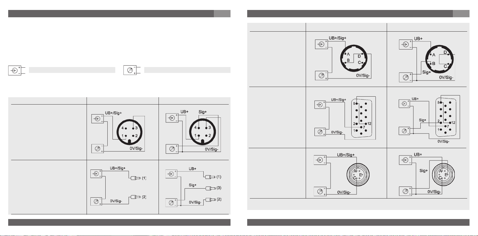
7. Mise en service, exploitation
F
En cas de transducteurs avec sortie de courant, des afficheurs et des dispositifs d‘évaluation
externes peuvent être alimentés directement de la boucle de courant. À cette occasion, il faut
prendre en considération une baisse de tension spécifique supplémentaire.provoquée par
l‘afficheur. Pour l‘affichage emboîtable à ultra haute puissance type WUR-1, cette baisse de
tension supplémentaire est de 6 V. Les transducteurs sont momentanément résistants aux
courts-circuits; cependant il faut éviter une erreur de câblage de l‘instrument.
7. Mise en service, exploitation
Connecteur baionnette
4 pôles
IP 65 (NEMA 4) *
Code de commande: O4
)
2-fils
F
3-fils
Alimentation
Recépteur
UB+/Sig+ Alimentation positive / raccord mesure
OV/Sig- Alimentation négative / raccord mesure
2-fils 3-fils
Connecteur
M 12x1, 4 pôles
IP 65 (NEMA 4) *
Code de commande: M4
Sortie câble avec 1,5 m longleur,
section de conducteur jusqu'à un
maximum de 0,22 mm ², AWG 24
avec des embouts, diamètre extérieur du conducteur de 4,8 mm
IP 65 (NEMA 4)
Code de commande: DI
46
WIKA Operating instructions/Betriebsanleitung/Mode d'emploi/Instrucciones de servicio WU-1X
)
rouge
noir
rouge
brun
noir
SUB D connecteur
15 pôles
IP 54 (NEMA 3S)
Code de commande: TX
Connecteur R03
6 pôles
IP 54 (NEMA 3S)
Code de commande: U6
*) mit Side-Access IP 54 (NEMA 3S)
WIKA Operating instructions/Betriebsanleitung/Mode d'emploi/Instrucciones de servicio WU-1X
2460160.06 GB/D/F/E 01/2010
2460160.06 GB/D/F/E 01/2010
47
Page 25

7. Mise en service, exploitation
F
Données techniques Type WU-1X
WU-10 / WU-15
WU-16
Etendue de mesure bar 4 7 10 16 25 40 60 100 160 250 400
Limites de surcharge
Pression de destruction
Principe de mesurage Capteur à couche mince
Matériaux
Parties en contact avec le
fluide
Boîtier Acier inox
Qualité de l’état de surface Électro-poli, typ. Ra ≤ 0,18 µm (RA 7); max. ≤ Ra 0,25 µm (RA 10)
Volume mort mm
Fluide admissibles Fluides gazeux et liquides / vapeurs
Alimentation U
Charge capacitive max. 0,1 (Sortie tension)
Courant de sortie maxi mA < 1 Sortie tension; Source
Réglage: point zero % du gain
Temps de transmission (10 ... 90 %) ms
Rigidité diélectrique VDC 500
Précision % du gain
48
WIKA Operating instructions/Betriebsanleitung/Mode d'emploi/Instrucciones de servicio WU-1X
1)
1)
bar 40 70 100 160 250 400 550 720 720 720 720
B UB en VDC
psi 60 100 160 250 300 500 1000 1500 2000 3000 5000
bar 8 14 20 32 50 80 120 200 320 500 500
Autre etendue de mesure et unité (e.g. MPa, kg/cm
1)
1 bar = 14,50 psi
®
2.4711Elgiloy
3
mA < 30 Sortie courant
WU-10 < 1500, WU-15 < 1000, WU-16 < 1000
10 < U
et 0 ... 10 V)
(capteur); 316L VIM/VAR (raccord de pression)
B ≤ 30 (14 ... 30 V avec signal de sortie 0,1 ... 10,1 V
2
) sur demandee
± 5 (par potentiomètre)
≤
2
≤
0,25 pour étendue de mesure > 4 bar (BFSL)
% du gain
% du gain ≤ 0,5
% du gain ≤ 1,0
≤
0,5 pour étendue de mesure ≤ 4 bar (BFSL)
2)
pour étendue de mesure > 4 bar
2)
pour étendue de mesure ≤ 4 bar
7. Mise en service, exploitation
Données techniques Type WU-1X
2)
Inclusif non-linéarité, hystérésis, zéro et déviation de l’étendue de mesure
(correspond à l’erreur de mesure selon IEC 61298-2).
Calibré en position verticale, raccord de pression vers le bas.
Non-linéarité % du gain
% du gain
Stabilité sur un an % du gain
Température autorisée
Du fluide °C -40 ... +100
De l’environnement °C -20 ... +85
De stockage °C -40 ... +100
Plage compensée °C -20 ... +80
Coefficient de température sur
plage compensée
Coef. de temp. moy. du point 0 % du gain
Coef. de temp. moy. % du gain
Conformité - CE
Directive Equipements sous
Pression
CEM Directive
Résistance aux chocs g 500 selon IEC 60068-2-27 (chock méchanique)
Résistance aux vibrations g 10 selon IEC 60068-2-6 (vibration en cas de résonance)
Protection électrique
Résistance au court- circuit Sig+ contre UB- (momentanément)
Protection fausse polarité UB+ contre UB-
Poids kg Environ 0,1
≤
0,15 pour étendue de mesure > 4 bar (BFSL) selon IEC 61298-2
≤
0,3 pour étendue de mesure ≤ 4 bar (BFSL) selon IEC 61298-2
≤
0,2 (pour les conditions de référence)
≤
0,1 / 10 K
≤
0,15 / 10 K
97/23/EG
2004/108/CE, EN 61 326 Emission (groupe 1, classe B)
et résistance aux perturbations (secteur industriel)
Pour l‘exécution FM Approved, tenez compte des conditions de raccordement spéciales du
dessin de contrôle joint (Control drawing).
WIKA Operating instructions/Betriebsanleitung/Mode d'emploi/Instrucciones de servicio WU-1X
2460160.06 GB/D/F/E 01/2010
2460160.06 GB/D/F/E 01/2010
F
49
Page 26

7. Mise en service, exploitation / 8. Réglage du zéro
F
Veuillez prendre en considération lors de la conception de votre installation, que les
valeurs indiquées (par exemple pression d’éclatement, limite de surcharge) dépendent
de la matière utilisée, du filetage et du joint utilisé.
Vérification du fonctionnement
Le signal de sortie doit se comporter proportionnellement à la pression présente. Si ce
n’est pas le cas, ceci peut être une indication que la membrane est endommagée. Dans
ce cas veuillez lire “élimination de perturbations” dans le chapitre 10.
N’ouvrez les raccords que hors pression!
Prenez en considération les paramètres de service selon le chapitre 7
Avertissement
“Caractéristiques techniques”.
N'utilisez le transducteur qu'à l'intérieur de la zone limite de surcharge!
Considérez que quand vous touchez le transducteur en fonctionnement, la
surface des composants des appareils peut être brûlante.
Attention
8. Réglage du zéro
Les transduteurs de WIKA décrits ici ne nécessitent aucun entretien. Cependant si malgré tout
un décalage du zéro apparaissait, il peut être ajusté à l’aide du potentiomètre intégré.
Le contrôle et réglage du zéro se fait hors pression. Le potentiomètre se trouve, en tant que
protection contre des effetes mécaniques, à l’intérieur du boîtier. Pour le réglage il faut utiliser
un tournevis de 1 à 1,5 mm.
Un réglage du gain (après une correction du zéro) n’est pas nécessaire pour les transducteurs décrits ici.
8. Réglage du zéro
Déroulement en cas d‘instruments sans accès latéral
1. Séparez l’appareil de la tension d’alimentation avant de l’ouvrir.
2. Dévissez avec précaution la bague filetée. Retirez avec précaution le
raccord électrique du boîtier, pour autant que le permettent les
conducteurs.
3. Alimentez de nouveau l’appareil en tension.
4. Réglez le zéro hors pression, par l’intermédiaire du potentiomètre.
Ne provoquez pas de court-circuit avec le tournevis dans l’appareil.
Contrôlez le zéro à l’aide d’un appareil de mesure adéquat.
5. Séparez l’appareil de l’alimentation avant de le refermer.
6. Tournez le raccord électrique jusqu’au moment où il s’enclique dans
l’encoche prévue. Ensuite serrez la bague filetée à la main.
Déroulement en cas d‘instruments avec
accès latéral
1. Tournez l‘anneau de maintien jusqu‘à
dégager l‘accès au potentiomètre.
2. Évitez de toucher d‘autres composants
avec le tourne-vis pour ne pas provoquer
de court-circuits dans l‘instrument.
Tourner dans le sens des aiguilles de la
montre signifie décalage du zéro vers le
haut, tourner dans le sens inverse signifie
décalage du zéro vers le bas.
3. Tournez ensuite la bague filetée jusqu‘à ce
que l‘accès au potentiomètre est de
nouveau refermé.
F
En cas de problèms
(+49) 9372/132-295
50
WIKA Operating instructions/Betriebsanleitung/Mode d'emploi/Instrucciones de servicio WU-1X
WIKA Operating instructions/Betriebsanleitung/Mode d'emploi/Instrucciones de servicio WU-1X
2460160.06 GB/D/F/E 01/2010
2460160.06 GB/D/F/E 01/2010
51
Page 27

9. Entretien, accessoires
F
9. Entretien, accessoires
Les transducteurs WIKA ne demandent aucune maintenance.
Ne faites effectuer les réparations que par le fabricant.
Échange de la carte électronique
L‘échange de la carte se fait hors pression.
Avant d‘ouvrir l‘appareil, déconnectez-le de l‘alimentation.
Veillez lors du montage à ce que tous les composants soient protégés contre un contact
direct.
Démontage de la carte électronique
1. Pour éviter des dégâts, il faut protéger
l‘instrument resp. la nouvelle carte contre
des tensions resp. une décharge statique.
2. Il faut séparer l‘instrument, avant de l‘ouvrir,
de la tension d‘alimentation.
3. Dévissez avec précaution la bague filetée.
Retirer avec précaution, autant que le
permettent les conducteurs, la connexion
électrique du boîtier. Ensuite, séparez
prudemment les conducteurs/fiches de
la carte.
4. Introduisez l‘outil livré avec la carte
d‘échange dans le perçage de la carte.
5. Maintenez le transducteur et retirez la carte
électronique du boîtier
Installation de la carte électronique
1. Introduire dans le boîtier, autant que possible et à pression modérée, la nouvelle carte à
l‘intérieur des guide-cartes.
2. Enficher le mini-connecteur du raccord électrique dans la fiche de la carte électronique.
3. Placer le raccord électrique dans le transducteur, tourner le raccord électrique jusqu‘à ce
qu‘il s‘encliquète dans l‘encoche prévu à cet effet. Serrez l‘anneau fileté à la main.
52
WIKA Operating instructions/Betriebsanleitung/Mode d'emploi/Instrucciones de servicio WU-1X
without side-access
with side-access
9. Entretien, accessoires / 10. Elimination de perturbations
Accessoires. Les renseignements concernant les accessoires (par exemple connecteurs)
figurent dans le tarif de stock actuel, le ”Product Catalog” en CD-Rom ou veuillez prendre
contact avec notre département commercial.
10. Elimination de perturbations
N’ouvrez les raccords que hors pression!
Avertissement
Prenez des mesures de sécurité pour les restes de fluides se trouvant dans
!
Avertissement
N’utilisez aucun objet pointu ou dur pour le nettoyage, car la membrane du raccord
pression ne doit en aucun cas être endommagée.
Veuillez contrôler au préalable si la pression est présente (vannes / robinets à boisseau sphérique, etc. ouvert) et si vous avez choisi la tension d’alimentation correcte et le système de
câblage correspondant (2 fils/3 fils).
Perturbations Cause Mesures à prendre
Lors d‘une variation de pression le
signal de sortie reste constant
Pas de signal de sortie
Pas de / ou faux signal de sortie
WIKA Operating instructions/Betriebsanleitung/Mode d'emploi/Instrucciones de servicio WU-1X
2460160.06 GB/D/F/E 01/2010
2460160.06 GB/D/F/E 01/2010
les transducteurs de pression démontés. Ces restes de fluides peuvent
mettrent en danger les personnes, l’environnement ainsi que l’installation !
Si vous ne pouvez pas éliminer des dérangements sur le transducteur,
mettez celui-ci hors service et protégez le contre une remise en service par
inadvertance.
Ne faites effectuer les réparations que par le fabricant.
Surcharge mécanique par pression
excessive
Fausse tension d‘alimentation ou
pointe de surtension
Tension d‘alimentation manquante /
fausse ou pointe de surtension
Rupture de conducteur Contrôler le passage du courant
Erreur de câblage (par ex. systeme a 2
fils connecté en systeme a 3 fils)
Remplacer l‘appareil; en cas de panne
répétitive consulter le fabricant *)
Remplacer l‘appareil
Corriger la tension d‘alimentation selon
le mode d‘emploi *)
Respecter la position des raccords (voir
plaquette signalétique / mode d‘emploi)
F
53
Page 28

10. Elimination de perturbations
F
Perturbations Cause Mesures à prendre
Signal de sortie divergent ou
zéro du signal diverge
Zéro du signal diverge
Gains du signal tombe / est trop faible
Gain du signal trop faible
En cas de réclamation non justifiée, nous mettrons en facture les coûts de traitement de celle-ci.
*) Contrôlez après le réglage le fonctionnement correct du système. Au cas où l’erreur persiste, renvoyez l’appareil pour
réparation (ou remplacez l’appareil).
Déréglage du zéro
Température du fluide ou ambiante trop
élevée / trop basse
Endommagement de la membrane, par
ex. par des coups, des fluides abrasifs
/ agressifs; corrosion sur la membrane /
sur les raccords de pression
Endommagement de la membrane, par
ex. par des coups, des fluides abrasifs
/ agressifs; corrosion sur la membrane /
sur les raccords de pression
Tension d‘alimentation trop élevée /
trop basse
Surcharge mécanique par pression
excessive
Régler le zéro correctement(voir
chapitre 8), utiliser un appareil de
mesure de courant / tension d‘une
précision suffisante.
Utiliser l‘appareil a l‘intérieur de la plage
de température autorisée; tenir compte
de l‘erreur de température autorisée
(voir le mode d‘emploi)
Remplacer l‘appareil
Prendre contact avec le fabricant et
remplacer l‘appareil
Corriger la tension d‘alimentation selon
le mode d‘emploi
Recalibrer l‘appareil *)
Si un problème reste présent, veuillez prendre contact avec notre département commercial.
Certificat de matière de processus (déclaration de contamination en cas de réparation)
Veuillez laver ou nettoyer les appareils démontés avant de les renvoyer afin de protéger
nos employés et l’environnement des risques présentés par les résidus de fluide adhérents.
Un contrôle des appareils en panne ne peut être effectué de façon sure que si la déclaration de contamination est complète. Cette déclaration comporte toutes les matières
ayant été en contact avec l’appareil, également celles ayant été utilisées lors d’essais,
en service ou lors du nettoyage. La "Product Return Form" peut être déchargée de notre
adresse Internet (www.wika.de / www.wika.com)
54
WIKA Operating instructions/Betriebsanleitung/Mode d'emploi/Instrucciones de servicio WU-1X
11. Stockage, mise au rebut
11. Stockage, mise au rebut
Veuillez prendre les précautions de sécurité pour la mise au rebut et pour
!
Avertissement
Stockage
Remontez le capuchon de protection lors du stockage de l’appareil.
Mise au rebut
Mettez les composants des appareils et les emballages au rebut en respectant les
prescriptions nationales pour le traitement et la mise au rebut des régions de livraison.
WIKA se réserve le droit de modifier les présentes spécifications.
WIKA Operating instructions/Betriebsanleitung/Mode d'emploi/Instrucciones de servicio WU-1X
2460160.06 GB/D/F/E 01/2010
2460160.06 GB/D/F/E 01/2010
le stockage des fluides se trouvant dans les transducteurs démontés.
Nous recommandons un nettoyage approprié et méticuleux. Ces restes de
fluides peuvent mettrent en danger les personnes, environnement ainsi que
l’installation !
F
55
Page 29

1. Detalles importantes para su información / 2. Resumen rápido para usted
E
1. Detalles importantes para su información
Lea estas instrucciones de servicio antes del montaje y puesta en servicio del transductor.
Guarde las instrucciones de servicio en un lugar accesible a cualquier usuario en cualquier
momento.
Las siguientes instrucciones de montaje y de servicio han sido redactadas cuidadosamente.
Pero a pesar de ello no es posible tener en cuenta todos los casos de aplicación. Si echara en
falta informaciones para su problemática específica, podrá obtener más información:
A través de nuestra dirección de Internet www.wika.de / www.wika.com
La designación de la ficha técnica correspondiente PE 87.05
Asesores de utilización (+49) 9372/132-295
Para números de modelos especiales, p.ej. WU-10000, WU-15000 o WU-16000, tenga en
cuenta las especificaciones según albarán de entrega. Si el número de serie en el placa de
identificación se vuele ilegible (p. ej. por daños mecánicos o sobrepintado) ya no es posible la
posibilidad de seguimiento.
Los transductores WIKA descritos en las instrucciones de servicio son diseñados y fabricados conforme a los conocimientos más recientes. Todos los componentes están sometidos
a unos estrictos criterios de calidad y medioambientales durante la fabricación. Nuestro
sistema de gestión medioambiental posee la certificación según la norma DIN EN ISO 14001.
Antes de expedirlo, el instrumento ha sido probado, limpiado y empaquetado con cuidado
bajo atmósfera inerte.
Utilización del producto según el uso de destinación WU-1X
Utilice el transductor de presión para convertir la presión en una señal eléctrica.
Conocimientos requeridos: Instale y ponga en servicio el transductor sólo si está familiarizado con las regulaciones y directivas relevantes de su país y si posee la cualificación
necesaria. Debe estar familiarizado con las reglas y las regulaciones de las áreas de riesgo de
explosión, de la tecnologia de medicíon y control y los circuitos eléctricos, ya que el transductor es „equipo eléctrico“ definido por EN 50178. Según las condiciones de aplicación,
debe poseer los conocimientos corres-pondientes de, p.ej. medios agresivos.
2. Resumen rápido para usted
Si quiere un resumen rápido, léase las secciones 3, 5, 7 y 11. Allí, encontrará instrucciones
para su seguridad y importantes informaciones sobre su producto y la puesta en funcionamiento. Es imprescindible leerlas.
56
WIKA Operating instructions/Betriebsanleitung/Mode d'emploi/Instrucciones de servicio WU-1X
3. Signos, símbolos y abrevaciones / 4. Función / 5. Para su securidad
3. Signos, símbolos y abrevaciones
El producto cumple con las
directivas europeas respectivas.
!
Advertencia
Advertencia
Advertencia
Peligro potencial para su
vida o lesiones graves.
Peligro potencial para su
vida o lesiones graves por
coponentes proyectados.
Peligro potencial de
quemaduras por superficies calientes.
Nota, información importante, falla de funcionamiento.
2 hilos Dos conexiones sirven para la
energía auxiliar.
El corriente de alimentación es el
señal de medición.
3 hilos Dos conexiones sirven para la
energía auxiliar.
Una conexión sirve para la señal de
medición.
4. Función
Ultra High Purity Transducer
WU-10: Single End; WU-15: Flow Through; WU-16: Modular Surface Mount
Función: Mediante un elemento sensor y el suministro de energía auxiliar, la presión existente
en su aplicación se convertirá en una señal eléctrica reforzada, estandarizada , a través de la
deformación de una membrana. Esta señal eléctrica cambia de forma proporcional respecto
de la presión y puede ser evaluada respectivamente.
5. Para su securidad
Seleccione el transductor adecuado con respecto al rango de medición,
!
Advertencia
WIKA Operating instructions/Betriebsanleitung/Mode d'emploi/Instrucciones de servicio WU-1X
2460160.06 GB/D/F/E 01/2010
2460160.06 GB/D/F/E 01/2010
versión, condiciones de medición específicas antes de instalar o poner en
servicio el instrumento.
Observe el reglamento nacional relevante (p.ej. EN 50178) y, para aplica-
ciones especiales, tenga en cuenta las normas y directivas vigentes (p.ej.
en medios de medición peligrosos tales, materias inflamables o tóxicas así
como en instalaciones de refrigeración y compresores). Si no se observan
las prescripciones de seguridad, ¡eso puede tener consecuencias
graves como lesiones físicas graves y daños materiales!
E
57
Page 30

5. Para su securidad
E
6. Embalaje / 7. Puesta en servicio, funcionamiento
E
¡Abrir las conexiones de presión sólo en estado sin presión!
!
Advertencia
Al montar, atienda a proteger todos los componentes contra contactos directos.
Planee el modo de conexión con mucho cuidado al conectarlo a otros instrumentos.
Hay que respetar los límites de sobrecarga del rango de medición correspondiente.
Observe los parámetros de servicio según sección 7 „Datos técnicos“.
Asegurése de que se utilizen los instrumentos de acuerdo con su destinación, comode-
scrito en las siguientes instrucciones.
Abstenerse de intervenciones y modificaciones en el transductor no descritas en estas
instrucciones de servicio.
Ponga fuera de servicio el instrumento y protejalo contra la puesta en servicio por error, si
no puede eliminar las perturbaciones.
Sólo el fabricante puede efectuar reparaciones.
El usuario es responsable de la compatibilidad del material así como del manejo, funcio-
namiento y mantenimiento reglamentario.
La seguridad del usuario puede estar disminuida por el instrumento si, por ejemplo, éste:
- presenta daños visibles
- no funciona como debería
- ha sido almacenado durante mucho tiempo bajo condiciones inadecuadas.
En casos de duda debería devolver el instrumento al fabricante por revisión.
Las especificaciones respecto a resistencia a la corrosión y indifusibilidad de los materiales de
los instrumentos las encuentra en nuestro manual WIKA Medición de presión y de temperatura.
¡Tome medidas de precaución en cuanto a residuos de medios de
medición en transductores de presión desmontados. Medios residuales
pueden causar daños en personas, medio ambiente y equipo!
6. Embalaje
¿Se entregó todo?
Verifique el volumen del suministro
Transductor de presión completos
Rogamos revisen los equipos por eventuales daños que se hayan producido durante
el transporte. Si detectara daños visibles, debe comunicarlo inmediatamente al transportista y a WIKA.
Los transductores UHP se han limpiado, evacuado y empaquetado doblemente en
salas limpias bajo atmósfera inerte (clase de sala limpia 100). Los racordajes (fittings)
de alta calidad están protegidos con tapas plásticas especiales. Deje estos instrumentos en este embalaje especial hasta su instalación para protegerlos contra deterioro y contaminación. La lámina de protección ESD (Electro-Static-Discharge) sólo
debe retirarse en el lugar de aplicación.
Guárdese el embalaje ya que éste ofrece una protección ideal durante el transporte
(p.ej. lugar de instalación cambiante, envío para revisión).
Procure que la rosca de conexión de presión y los contactos de unión no resulten
dañados.
Saque este capuchón solamente justo antes de la instalación.
Reinstale el capuchón protector al desmontaje y transporte del instrumento.
Desembalaje de los instrumentos
1. Saque el transductor del cartón.
2. Después, retire con cuidado el primero plástico transparente sin dañar la lámina ESD.
3. Transporte el instrumento inclusive la lámina de protección ESD a la sala limpia.
58
WIKA Operating instructions/Betriebsanleitung/Mode d'emploi/Instrucciones de servicio WU-1X
7. Puesta en servicio, funcionamiento
Herramienta necesaria: llave de boca SW SW 19 und 16, destornillador de tamaño
1 a 1,5 mm, tijeras, juego de llaves allen para WU-16
WIKA Operating instructions/Betriebsanleitung/Mode d'emploi/Instrucciones de servicio WU-1X
2460160.06 GB/D/F/E 01/2010
2460160.06 GB/D/F/E 01/2010
59
Page 31

7. Puesta en servicio, funcionamiento
Montaje de la conexión mecánica
¡No utilice esta
superficie de
llave!
¡Utilice esta superficie de
llave para atornillar!
Placa de identificación (ejemplo)
Señal de salida
Alimentación
N° de serie
S #
Código artículo
P #
Ocupación de las conexiones
Fecha de fabricación codificada
Saque este capuchón solamente justo antes de la instalación.
Asegúrese, al montaje, de que las superficies de estanqueidad del instrumento y de
los puntos de medición queden limpias y intactas.
No rasque las faldas obturadoras. Apretar excesivamente puede deteriorar las faldas
obturadoras y provocar posibles fugas.
Atornille o destornille el instrumento sólo a través de las superficies de llave utilizando
una herramienta apropiada y el momento de torsión prescrito. El momento de torsión
prescrito depende de la dimensión de la conexión de presión y de la junta utilizada
(forma/material). No utilize la caja del instrumento para atornillar o destornillarlo.
Al atornillar, asegúrese de que las vueltas de rosca no resulten ladeadas.
Conexión mecánica
Prepare las conexiones de las líneas de gas adecuadamente.
Debería limpiar todos los componentes de conexión, como p.ej. juntas planas con gas
puro/filtrado.
60
WIKA Operating instructions/Betriebsanleitung/Mode d'emploi/Instrucciones de servicio WU-1X
E
7. Puesta en servicio, funcionamiento
Racordajes (sólo WU-10 / WU-15)
Para racordajes (fittings) con roscas interiores resp. roscas exteriores compatibles con
conexiones VCR
1. Sostenga la tuerca racor/tornillo de apriete o accesorios resp. el hexágono de caja.
Atornille a mano la tuerca racor y alínee en la posición deseada el instrumento. Al atornillar
y desatornillar en los accesorios o fittings atienda a que las vueltas de rosca no se
bloqueen.
2. Sostenga la tuerca racor con un llave de boca adecuado. Apriete la tuerca racor/tornillo de
apriete o los accesorios con un giro de 1/8 resp. 1/4 (en fonción de las juntas utilizadas)
por encima de la posición atornillada a mano.
3. Observe también las correspondientes especifiaciones técnicas y informaciones de los
fabricantes de conexiones específicas (prensaestopas + fittings).
4. Con eso, el transductor está juntado mecánicamente. Las posibilidades de conexiones
eléctricas se tratarán en el capítulo siguiente.
Conexiones soldadas (sólo WU-10 / WU-15)
La soldadura debe estar soldada completamente y sin interrupción. No obstante, fíjese a una
acción mínima de corriente y calor sobre los instrumentos. Como refrigeración, recomendamos el paso de argón durante el proceso de soldeo. Se recomienda realizar unas soldaduras de prueba antes del soldeo propio
Advertencia
Acabado
1. Eventualmente, el cero debe ajustarse (vea punto ajuste de cero).
2. Compruébe todas las conexiones mecánicas (fittings, soldaduras) por medio de prueba
adecuada (por ej. detección de fugas por helio) que estén impermeables.
WIKA Operating instructions/Betriebsanleitung/Mode d'emploi/Instrucciones de servicio WU-1X
2460160.06 GB/D/F/E 01/2010
2460160.06 GB/D/F/E 01/2010
E
Observe las correspondientes instrucciones para el montaje de las juntas planas utilizadas
específicas del fabricante. Ahora puede retirar la lámina de protección así como las tapas
de plástico eventualmente presentes para la protección de las conexiones de alta calidad.
®
vale:
Asegúrese antes de la soldadura por arco voltaico de que el transductor no
!
esté conectado a ningún otro aparato.
Desconécte todas las conexiones eléctricas del transductor.
Evítelo rigurosamente que líneas de alimentación del flexible de conexión
entren en contacto con superficies de metales.
61
Page 32
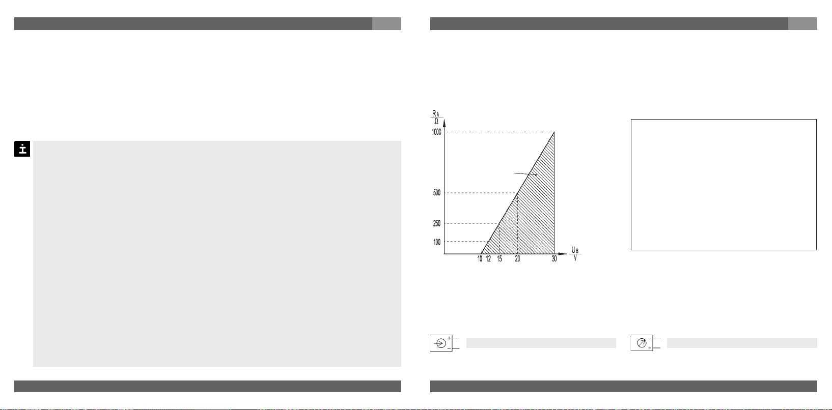
7. Puesta en servicio, funcionamiento
E
3. Debería poner en circuito y cortar el flujo de gas al menos diez veces para eliminar corpús
culos eventualmente penetrados durante la instalación. La tasa del flujo de gas debe
corresponder al flujo de proceso posterior.
Conexiones MSM (sólo WU-16)
Tenga en cuenta las especificaciones técnicas correspondientes, tales como torques y posición de montaje de los componentes de conexión.
Montaje de la conexión eléctrica
Conecte a tierra el instrumento a través de la conexión de presión.
Utilice el transmisor de presión con un cable blindado y ponga a tierra el blindaje,
como mínimo en un lado del cable, cuando los cables tengan una longitud superior
a 30 m (conductor doble) o 3 m (conductor triple o cuádruple) o salgan al exterior del
edificio.
Utilice exclusivamente fuentes de corriente que garanticen una desconexión elec-
trónica segura de la tensión de servicio conforme a la IEC/DIN EN 60204-1. Preste
también atención a las exigencias generales para circuitos PELV de conformidad con
IEC/DIN EN 60204-1.
Modo de protección IP según IEC 60 529 (las clases de protección indicadas se
aplican sólo cuando el transmisor de presión esté conectado a unas hembrillas
procurando el modo de protección correspondiente).
Escoje el diámetro de cable de forma que sea apropiado para la boquilla de paso de
la clavija. Asegúrese de que el racor de cable de la clavija ensamblada sea posicionado correctamente y que existan juntas no deterioradas. Aprete el racordaje y
verifique la posición correcta de las juntas para asegurar el modo de protección.
Asegúrese de que en las salidas de cables no entre ninguna humedad a la extre-
midad del cable.
Preste atención a obturar correctamente la conexión eléctrica (estanqueizada) (p.ej.
acoplamiento M12).
62
WIKA Operating instructions/Betriebsanleitung/Mode d'emploi/Instrucciones de servicio WU-1X
7. Puesta en servicio, funcionamiento
La conexión eléctrica de los transductores se establece por ficha.
Como energía auxiliar, un voltaje continuo dentro de los límites especificados es suficiente.
Energía auxiliar U
B: 10 VDC < UB ≤ 30 V (14 ... 30 V con energía auxiliar 0,1 ... 10,1 V y
0 ... 10 V). El nivel de tensión no debe excederse en el circuito del lazo de corriente.
La relación entre alimentación y resistencia de carga (RA) está especificada en el dibujo:
Energía auxiliar y carga óhmica máx. admisible
4 ... 20 mA, 2 hilos
Salida de corriente (sistema 2 hilos)
4 ... 20 mA:
R
A ≤ (UB – 10 V) / 0,02 A
Área
permisible
Salida de tensión (sistema 3 hilos)
0,1 ... 5,1 V: RA > 5 kOhm
0,1 ... 10,1 V:
1 ... 5 V:
0 ... 5 V:
0 ... 10 V:
A en Ohm y UB en Volt
R
RA > 10 kOhm
RA > 5 kOhm
RA > 5 kOhm
RA > 10 kOhm
En transmisores con salida de corriente, indicadores y dispositivos de evaluación externos
pueden alimentarse directamente del lazo de corriente. En esto, hay que considerar una caída
de tensión específica adicional causada por el dispositivo indicador. En el indicador enchufable de potencia ultraelevada tipo WUR-1, esta caída de tensión adicional es de 6 voltios. Los
transmisores están, por poco tiempo, resistentes al cortocircuito; no obstante, hay que evitar
un modo de conexión incorrecto.
Fuente de tensión
Consumidor
UB+/Sig+ Conexión de alimentación/medición positiva
OV/Sig- Conexión de alimentación/medición negativa
WIKA Operating instructions/Betriebsanleitung/Mode d'emploi/Instrucciones de servicio WU-1X
2460160.06 GB/D/F/E 01/2010
2460160.06 GB/D/F/E 01/2010
E
63
Page 33
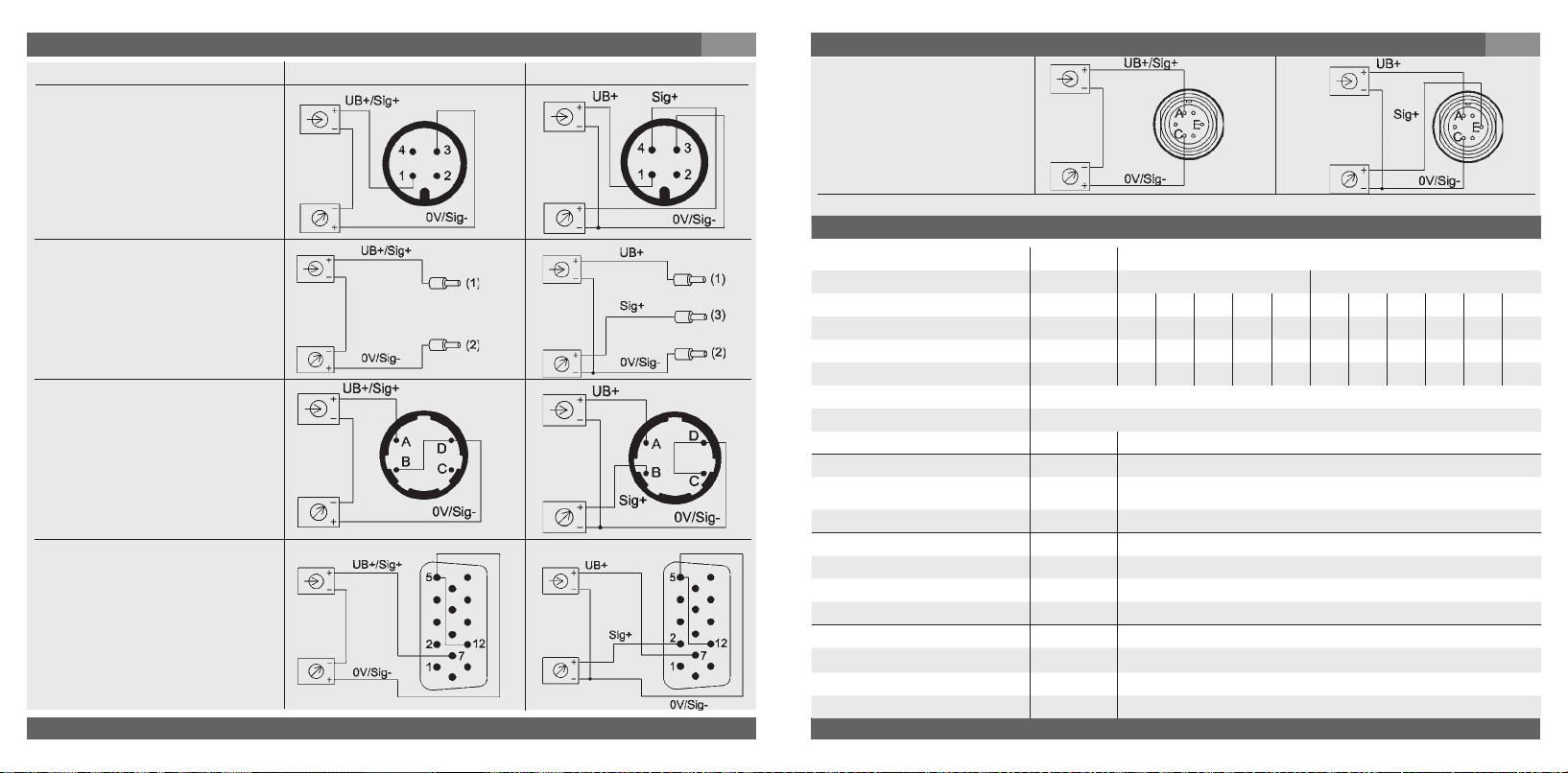
7. Puesta en servicio, funcionamiento
Sistema 2 hilos
Sistema 3 hilos
Conector circular
M 12x1, 4 polar
IP 65 (NEMA 4) *
)
Código de pedido: M4
Salida de cable con una longitud
de 1,5 m , sección de conduc-
rojo
tores max. 0,22 mm², AWG 24 con
virolas de cable, diámetro exterior
del conductor 4,8 mm
IP 65 (NEMA 4)
Código de pedido: DI
negro
Conector circular de bayoneta
4 polar
IP 65 (NEMA 4) *
)
Código de pedido: O4
SUB D conector
15 polar
IP 54 (NEMA 3S)
Código de pedido: TX
64
WIKA Operating instructions/Betriebsanleitung/Mode d'emploi/Instrucciones de servicio WU-1X
rojo
marrón
negro
E
7. Puesta en servicio, funcionamiento
Conector circular R03
6 polar
IP 54 (NEMA 3S)
Código de pedido: U6
)
*
con Side-Access IP 54 (NEMA 3S)
Datos técnicos Tipo WU-1X
Rango de medición bar 4 7 10 16 25 40 60 100 160 250 400
Límite de sobrecarga
Presión de rotura
Principio de medida Sensor de película delgada metálico
Material
medio
Acabado superficial Electropulido, típ. Ra ≤ 0,18 µm (RA 7);
Volumen de espacio muerto mm
Medios permisibles Líquidos / gases / niebla
Energía auxiliar U
Carga capacitiva µF max. 0,1 (Salida de tensión)
Corriente de salida max. mA < 1 Señal de salida tensión; fuente
WIKA Operating instructions/Betriebsanleitung/Mode d'emploi/Instrucciones de servicio WU-1X
2460160.06 GB/D/F/E 01/2010
2460160.06 GB/D/F/E 01/2010
1)
1)
Piezas en contacto con el
Carcasa Acero CrNi
B UB en VDC 10 < UB ≤ 30 (14 ... 30 V con señal de salida 0,1 ... 10,1 V y 0 ... 10 V)
bar 8 14 20 32 50 80 120 200 320 500 500
bar 40 70 100 160 250 400 550 720 720 720 720
Otros rangos y unidades de presión (p.ej. MPa, kg/cm
1)
1 bar = 14,50 psi
3
mA < 30 Salida del corriente
60 100 160 250 300 500 1000 1500 2000 3000 5000
2.4711 Elgiloy
max. Ra ≤ 0,25 µm (RA 10)
WU-10 < 1500, WU-15 < 1000, WU-16 < 1000
WU-10 / WU-15
WU-16
2
) a petición
®
(sensor); 316L VIM/VAR (conexión de présion)
E
65
Page 34
7. Puesta en servicio, funcionamiento
Datos técnicos Tipo WU-1X
Posibilidad de ajuste punto cero % del rango
Tiempo de respuesta (10 ... 90 %) ms
Pruebade rigidez dieléctrica VDC 500
Precisión % del rango
% del rango
% del rango
% del rango
2)
No-Linealidad, histéresis y error de punto cero y span incluidas
(correspondiente al error de medición según IEC 61298-2).
Ajuste con posición vertical de instalación, conexión de presión hacia abajo.
No-Linealidad % del rango
% del rango
Estabilidad al año % del rango
Rangos de temperatura admisibles
Medio °C -40 ... +100
Entorno °C -20 ... +85
Almacenamiento °C -40 ... +100
Rango de temperatura compensado
Coeficientes de temperatura en el
rango de temperatura compensado
CT medio del punto cero % del rango
CT medio del rango % del rango
CE- Indicativo
Directiva para aparatos de
presión
CEM Directiva
Resistencia a choques g 500 conforme a IEC 60068-2-27 (impacto mecánico)
Resistencia a vibraciones g 10 conforme a IEC 60068-2-6 (vibración con resonancia)
66
WIKA Operating instructions/Betriebsanleitung/Mode d'emploi/Instrucciones de servicio WU-1X
°C -20 ... +80
± 5 por potenciómetro
2
≤
≤
0,25 para presiones > 4 bar (BFSL)
≤
0,5 para presiones ≤ 4 bar (BFSL)
2)
≤
0,5
para presiones > 4 bar (BFSL)
2
≤
1,0
para presiones ≤ 4 bar (BFSL)
0,15 para presiones > 4 bar (BFSL) conforme a IEC 61298-2
≤
≤
0,3 para presiones ≤ 4 bar (BFSL) conforme a IEC 61298-2
≤
0,2 (con condiciones de referencia)
0,1 / 10 K
≤
≤
0,15 / 10 K
97/23/EG
2004/108/CE, EN 61 326 Emisión (grupo 1, clase B) y resistencia
(sector industrial)
E
7. Puesta en servicio, funcionamiento / 8. Ajuste de cero
Datos técnicos Tipo WU-1X
Tipos de protección eléctrica
inversa
Peso kg Aprox. 0,1
En la versión FM Approved tenga en cuenta las condiciones de conexión especiales en el
dibujo de control adjunto (Control drawing).
Prueba de funcionamiento
Advertencia
Advertencia
8. Ajuste de cero
Los transductores WIKA aquí descritos están sin mantenimiento. No obstante, en caso de
que se presente un dislocamiento del cero, éste puede ajustarse por medio del potenciómetro incorporado.
La comprobación y el ajuste de cero se realiza en estado sin presión. El potenciómetro se
encuentra dentro de la caja para protegerlo contra efectos mecánicos. Para la compensación
se necesita un destornillador del tamaño 1 a 1,5 mm.
WIKA Operating instructions/Betriebsanleitung/Mode d'emploi/Instrucciones de servicio WU-1X
2460160.06 GB/D/F/E 01/2010
2460160.06 GB/D/F/E 01/2010
Resistencia a cortocircuitos Sig+ contra U
Protección contra polaridad
B+ contra UB-
U
B- (por poco tiempo)
En el momento de diseñar su instalación, por favor tome en cuenta que los valores
indicados (por ej. presión de rotura, seguridad de sobrepresión) dependen del material,
de la rosca y de la junta usado.
La señal de salida debe ser proporcional a la presión. Si no lo es, eso podría ser un
indicio de un deterioro de la membrana. Léase en este caso en la sección 10 „Eliminación de perturbaciones“.
¡Abra las conexiónes sólo en estado sin presión!
Tenga en cuenta los parámetros de servicio según sección 7 „Datos
técnicos“.
¡Respete el límite de sobrecarga del rango de medición respectivo!
Al tocar el transmisor de presión, tenga en cuenta de que las superficies
de los compontes del instrumento puedan calentarse durante el funcionamiento.
No es necesario un ajuste del alcance (después del ajuste de cero) para los transductores aquí descritos.
E
67
Page 35
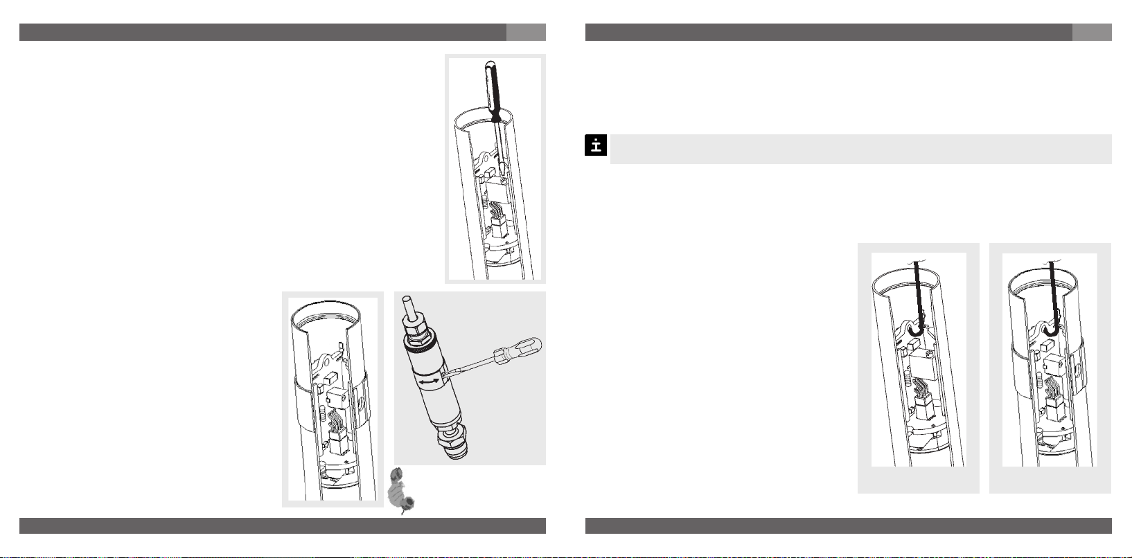
8. Ajuste de cero
Procedimiento en caso de instrumentos sin acceso lateral
1. Desconecte el instrumento de la alimentación antes de abrirlo.
2. Destornille con cuidado el anillo roscado. Desenchufe la conexión
eléctrica de la caja por lo que lo permiten los conductores.
3. Alimente de nuevo el instrumento.
4. Ajuste el cero con el potenciómetro en estado sin presión.
Tenga cuidado a no tocar otros componentes con el destornillador que
no provoque un cortocircuito en el instrumento. Compruebe el cero por
medio de un dispositivo adecuado. Girar en el sentido de las agujas del
reloj significa un desplazamiento del cero hacia arriba, girar en contra
del sentido de la agujas del reloj significa un desplazamiento del cero
hacia abajo.
5. Antes de cerrarlo, desconecte el instrumento de la alimentación.
6. Gire la conexión eléctrica hasta que engatille en la acanaladura prevista.
Luego apriete a mano el anillo roscado. El transductor puede
nuevamente ser puesto en servicio.
Procedimiento con instrumentos con
acceso lateral
1. Gire el anillo hasta que el acceso al
potenciómetra esté al descubierto.
2. Ajuste el cero con el potenciómetro en
estado sin presión. Tenga cuidado a no
tocar otros componentes con el
destornillador que no provoque un
cortocircuito en el instrumento.
Compruebe el cero por medio de un
dispositivo adecuado.
Girar en el sentido de las agujas del reloj
significa un desplazamiento del cero hacia
arriba, girar en contra del sentido de
la agujas del reloj significa un
Para más información
(+49) 9372/132-295
desplazamiento del cero hacia abajo.
68
WIKA Operating instructions/Betriebsanleitung/Mode d'emploi/Instrucciones de servicio WU-1X
E
8. Ajuste de cero / 9. Mantenimiento, accessorios
3. A continuación, gire el anillo hasta cerrar de nuevo el acceso al potenciómetro.
9. Mantenimiento, accessorios
Recambio de la tarjeta electrónica
El recambio se realiza en estado sin presión.
Desconecte el instrumento de la tensión de alimentación antes de abrirlo.
Al instalarlo, preste atención a proteger todos los componentes contra un contacto directo.
Desmontaje de la tarjeta electrónica
1. Para evitar un deterioro, hay que proteger
el instrumento resp. la nueva carta
electrónica contra tensiones resp.
descarga estática.
2. Antes de abrir el aparato, hay que
separarlo de la alimentación.
3. Retirar con cuidado el anillo roscado.
Sacar con cuidado la conexión eléctrica de
la caja por lo tanto que lo permitan los
cables. A continuación, separar con
cuidado los cables/clavijas de la carta.
4. Coloque la herramienta suministrada con
la carta de recambio en el taladro de la
carta.
5. Mantener el transmisor y retirar la carta de
la caja.
WIKA Operating instructions/Betriebsanleitung/Mode d'emploi/Instrucciones de servicio WU-1X
2460160.06 GB/D/F/E 01/2010
2460160.06 GB/D/F/E 01/2010
¡Los transductores WIKA estan libres de mantenimiento!
Sólo el fabricante puede efectuar reparaciones.
ohne side-access
E
mit side-access
69
Page 36
9. Mantenimiento, accessorios / 10. Eliminación de perturbaciones
E
Instalación de la carta
1. Introduzca con presión moderada la nueva platina en la caja tan lejos que sea posible
dentro del riel de guía.
2. Introducir el miniconectador enchufable de la conexión eléctrica en el enchufe de la carta.
3. Introducir la conexión eléctrica en el transmisor, dar vueltas a la conexión eléctrica hasta
engatillar en la acanaladura prevista para esto. Apretar a mano el anillo roscado.
Accesorios: Detalles para los accesorios (p. ej. conectores) encontrará en la lista de precios
WIKA, catálogo de productos WIKA sobre CD-Rom o póngase en contacto con nuestro
departamento de venta.
10. Eliminación de perturbaciones
¡Abrir las conexiones de presión sólo en estado sin presión!
Advertencia
¡Tome medidas de precaución en cuanto a residuos de medios de medición
!
Advertencia
Para no dañar las membranas de la conexión de presión, no utilizar para la limpieza
objetos puntiagudos ni duros.
Compruebe previamente si hay presión (válvulas/llave esférica, etc. abiertas), y si ha elegido la
fuente de tensión correcta y el tipo de cableado correspondiente (2 hilos/3 hilos).
en transductores desmontados. Medios residuales pueden causar daños en
personas, medio ambiente y equipo!
Ponga fuera de servicio el instrumento y protejalo contra la puesta en
servicio por error, si no puede eliminar perturbaciones.
Sólo el fabricante es autorizado para efectuar reparaciones.
10. Eliminación de perturbaciones
Avería Posible causa Medida
Señal de salida constante en caso de
cambio de presión
Sin señal de salida
Sin o falsa señal de salida
Señal de salida distinta o
Desviación de la señal del cero
Desviación de la señal del cero
Señal cae o demasiado baja
Alcance de la señal demasiado
pequeño
En caso de reclamación sin justificación alguna, tendrá que abonar los costes de tramitación de la reclamación.
*) Tras el ajuste, compruebe el funcionamiento correcto del sistema. Si el error persiste, envíe el aparato a reparar (o reemplácelo).
Sobrecarga mecánica por presión
excesiva
Falsa tensión de alimentación o golpe
de corriente
Sin o falsa tensión de alimentación o
golpe de corriente
Ruptura de línea Comprobar continuidad
Error de cableado (p. ej. sistema a 2
hilos cableado en 3 hilos)
Desajuste del cero
Temperatura del medio o ambiental
demasiado alta/baja
Deterioro de la membrana, p.ej. por
golpes, medios abrasivo/agresivo;
corrosion en membrana/racor de
presión
Deterioro de membrana, p. ej. por
golpes, medio abrasivo/agresivo;
corrosión en membrana/racor de
presión
Tensión de alimentación demasiado
alta/baja
Sobrecarga mecánica por sobrepresión Recalibrar el instrumento *)
Cambiar el instrumento; en caso de
fallo repetido, consultar con el fabricante *)
Cambiar el instrumento
Corregir tensión de alimentación según
instrucciones de servicio *)
Observar empleo de los conductores
(ver placa indicad. de tipo / instrucciones de uso)
Ajustar el cero correctamente (ver
capítulo 8), utilizar un instrumento de
medición de corrente / tensión suficientemente exacto.
Accionar instrumento dentro del rango
de temperatura; observar error de
temperatura admisible (véase instrucciones de uso)
Cambiar el aparato
Contactar con el fabricante y cambiar el
instrumento
Corregir tensión de alimentación según
instrucciones de uso
E
70
WIKA Operating instructions/Betriebsanleitung/Mode d'emploi/Instrucciones de servicio WU-1X
WIKA Operating instructions/Betriebsanleitung/Mode d'emploi/Instrucciones de servicio WU-1X
2460160.06 GB/D/F/E 01/2010
2460160.06 GB/D/F/E 01/2010
71
Page 37

10. Eliminación de perturbaciones / 11. Almacenaje, eliminación de desechos
Si el problema perdura, póngase en contacto con nuestro departamento de venta.
Certificado de process material (declaración de contaminación en caso de asistencia
técnica)
Fregue / limpie los instrumentos desmontados antes de la devolución a la fábrica, con
el fin de proteger a nuestros empleados y al medio ambiente de los peligros ocasionado
por los residuos de medios de medición adheridos. Una revisión de instrumentos con
avería sólo se puede efectuar seguramente, si se ha presentado una declaración de
contaminación completamente llenada. Tal declaración contiene informaciones sobre
todos materiales en contacto con el instrumento hasta los que se utilizaban por fines
de prueba, funcionamiento o limpieza. La declaración de contaminación es disponible a
través de nuestra página web (www.wika.de / www.wika.com).
E
11. Almacenaje, eliminación de desechos
Al almacenar los instrumentos o eliminar los desechos tome medidas
!
Advertencia
Almacenaje
Al almacenaje del transductor hay que montar el capuchón de protección.
Eliminación de los desechos
Elimine los desechos de componentes de instrumentos y materiales de embalaje según
el reglamento respectivo del tratamiento de residuos y eliminación de desechos de la
región o del país donde el instrumento se ha suministrado.
de precaución en cuanto a residuos de medios de medición en transductores desmontados. Recomendamos que la limpieza se realice de
forma adecuada y cuidadosa. Medios residuales pueden causar daños en
personas, medio ambiente y equipo.
WIKA se reserva el derecho de modificar las especificaciones detalladas.
72
WIKA Operating instructions/Betriebsanleitung/Mode d'emploi/Instrucciones de servicio WU-1X
2460160.06 GB/D/F/E 01/2010
 Loading...