

WIKA TXA2CL, TXS2CL, TXA4CL, TXS4CL, TXA2QL Instruction Manual
...
INSTRUCTION MANUAL
TEMPERATURE SWITCHES SERIE TXS, TXA
NI-492WE
Rev. 4 05/18
WEATHERPROOF AND INTRINSICALLY SAFE:MODELS TXS; FLAMEPROOF: MODELS TXA
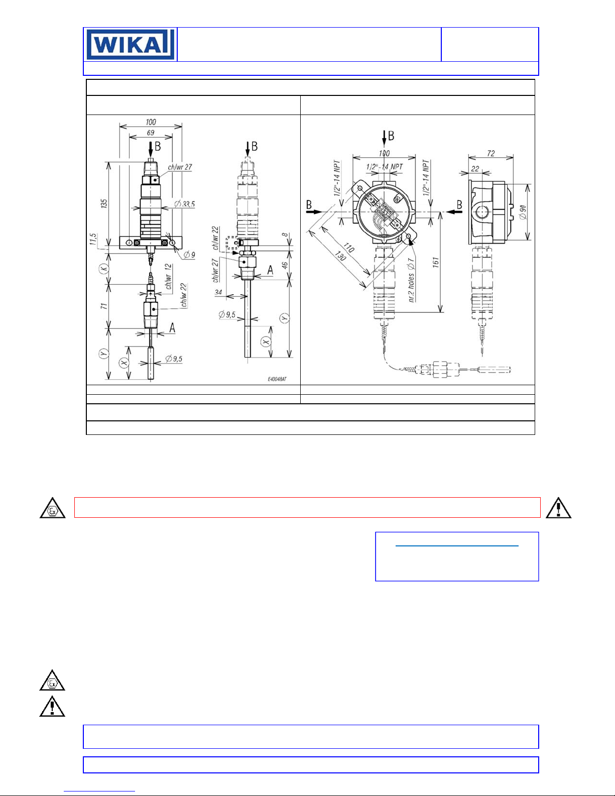
CORD CABLE INSTRUMENT INSTRUMENT WITH JUNCTION BOX
Stem Type C-Q-R Stem Type B
WEIGHT 0,4kg Dimension in mm WEIGHT 1kg Dimension in mm
Stem Type B: Y = 125mm ; X = 50mm
Stem Type C: K = 2m ; Y max. = 350mm Stem Type R: K = 10m ; Y max. = 1800mm
For surface mounting use two screws M6 (not supplied with the instrument)
NOTE: dimensions and weights are not binding unless released on certified drawings.
CAUTION
Before installing, using or carrying out maintenance on the instrument it is necessary to read and understand the indications given
in the attached Instruction Manual.
The instrument must only be installed and maintained by qualified personnel in relation to working with instruments for hazardous
areas.
INSTALLATION IS TO BE CARRIED OUT ONLY AFTER CHECKING THAT INSTRUMENT CHARACTERISTICS ARE
CONSISTENT WITH PROCESS AND PLANT REQUIREMENTS.
The functional features of the instrument and its degree of protection are shown on the identification plate fixed to the case.
CONTENTS:
GENERAL
1 2 -OPERATING PRINCIPLE
3 -MODEL CODE
4 -NAMEPLATE AND MARKINGS
5 -SPECIAL CONDITIONS FOR SAFE USE (X)
6 -SET POINT ADJUSTMENT
7 -SET POINT CALIBRATION
8 -INSTRUMENT PLUMBING
9 -MOUNTING AND CONNECTIONS
10 -PUTTING INTO OPERATION
11 -VISUAL INSPECTION
12 -FUNCTIONAL VERIFICATION
13 -STOPPING AND DISMOUNTING
14 -DISPOSAL
15 -TROUBLE SHOOTING
SAFETY INSTRUCTIONS FOR USE IN EXPLOSIVE ATMOSPHERES
RECOMMENDATIONS FOR THE SAFE USE OF THE INSTRUMENT
Stem Type Q: K = 5m ; Y max. = 900mm
DOCUMENT CORRELATED
to document authenticated with certificates
N° IECEx PRE 16.0073X
N° IECEx PRE 16.0074X
All data, statements and recommendations supplied with this manual are based on information believed by us to be reliable. As the conditions of effective
use are beyond our control, our products are sold under the condition that the user himself evaluates such conditions before following our recommendations
for the purpose or use foreseen by him.
This document is the property of ALEXANDER WIEGAND SE &Co and may not be reproduced in any form, nor used for any purpose other than for which
it is supplied.
INSTRUCTION MANUAL
range
Max working
temperature
(T max.)
Shall not exceed the
maximum
temperature specified
on the nameplate
(see fig.1 item 5).
Max electrical rating
(resistive load)
5A@24V d.c.; 5A@250V a.c.
See nameplate of the instrument
(electrical rating)
Max electrical
rating
(resistive load)
5A@24V d.c.;
5A@250V a.c.
See nameplate of
the instrument
(electrical rating)
1 - GENERAL
1.1 FOREWORD
The wrong choice of a models or a version, as well as the
incorrect installation, lead to malfunction and reduce instrument
life. Failure to follow the indications given in this manual can
cause damage to the instrument, the environment and persons.
1.2 ALLOWED OVERRANGES
Temperature exceeding the working range can be allowed only
for testing proposal up to the proof temperature. Continuous
temperature exceeding the (adjustable) “RANGE* (see fig 1) can
be applied to the instrument, provided they are clearly stated in
the instrument features (see fig.1, “MAX TEMPERATURE”).
The current and voltage values stated in the technical
specifications and data plate must not be exceeded: transitory
overranges can have a destructive effect on the switch.
1.3 TEMPERATURES
The temperature of the instrument is influenced by the
environmental and process temperature. Special attention must
be taken to avoid the exceeding of the limits specified in table 1
and 2.
For the instrument version TX**B* (stem for direct mounting) the
following table is applicable
Table 1 – Temperature conditions
Temp.
Classification
T6
T5
T4
T3
T2
T1
Ambient
temperature
range (Tamb)
-50 … +60 °C
-50 … +85 °C
For the instrument versions TX**C*, TX**Q*, TX**R* (stem for
remote mounting) and TX**S* (helical bulb for ambient
temperature) the following table is applicable
Table 2 – Temperature conditions
Temperature
Classification
T6
T5
T4
T3
T2
T1
Ambient
temperature
(Tamb)
-50..+60 °C
-50..+85 °C
2 - OPERATING PRINCIPLE
The operating principle is based on a pressure measuring
element, connected via a capillary tube to a bulb. This system is
partially filled with a volatile liquid, the residual free volume being
filled by its saturated vapour. In this system a pressure is
generated which is a non-linear function of bulb temperature; this
pressure acts on a stainless steel diaphragm which applies a
force to a stiff disc; this force is directly proportional to the
temperature value to which the bulb is submitted and is
contrasted by an compression spring charged by a suitable bush.
When the force balance point is exceeded, the stiff disc shifts
and, by means of a rigid rod, activates one or two
simultaneous release electric microswitches. The
microswitches are of the rapid release type with automatic rearm.
When the temperature moves away from the set values,
returning towards the normal values, the switch is rearmed.
3 - MODEL CODE
See Annex 1
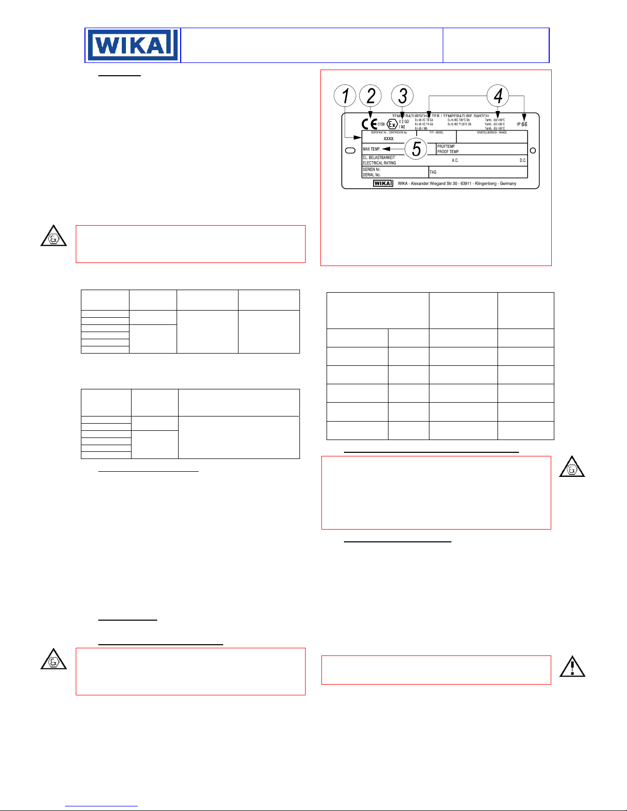
4 - NAMEPLATE AND MARKINGS
The i nstru ment is f itted wit h a metal plate beari ng al l its functional
characteristics and in case of flameproof or intrinsic safety
execution, also the markings prescribed by standard IEC/EN
60079-0. Fig.1 shows the plate mounted on flameproof
instruments.
NI-492WE
Rev.4 05/18
Fig. 1 - Flameproof instruments plate
1 Notified body that issued the type certificate and number of said
certificate.
2 CE marking and identification number of the notified body
responsible for production surveillance.
3 Apparatus classification according to ATEX 2014/34/EU
directive.
4 Type of protection and ambient temperature limits of operation.
5 Max working temperature
The following table gives the relationship between hazardous
areas, ATEX Categories and Equipment Protection Level (EPL)
listed on the flameproof instrument nameplate.
Hazardous area
Gas, vapours,
fog
Gas, vapours,
fog
Gas, vapours,
fog
Zone 0 1G Ga
Zone 1 2G or 1G Gb or Ga
Zone 2 3G, 2G or 1G Gc, Gb or Ga
Dust Zone 20 1D Da
Dust Zone 21 2D or 1D Db or Da
Dust Zone 22 3D, 2D or 1D Dc, Db or Da
5 - SPECIAL CONDITIONS FOR SAFE USE (X)
The instrument cannot be repaired (see also throubleshooting).
Should the instrument be installed without a junction box require
an electric connection suitable for the mode of protection chosen
at the free end of the cable.
Should the instrument be installed in mines (Group I) the elettrical
connection has require to be protected by chemical agents.
Therefore a mounting with cable protected by tubing is
mandatory.
6 - SET POINT ADJUSTMENT
The compression of the spring can be regulated by means of the
bush (for adjustment) in such a way that the switch is released
when the temperature reaches (either increasing or decreasing)
the desired value (set point). The instrument is usually supplied
with the switches set at 0°C or at the lowest setting range value
if this is higher than 0°C (factory calibration).
The instrument is supplied with an adhesive label showing the
set point calibration value. With factory calibration the values
are not indicated on the label as these are temporary and will be
modified with the definitive values. Prior to installation the
instrument must be calibrated and the definitive calibration
values written on the label.
If the instrument has been ordered with a specific calibration, it
is a good rule to check the calibration values marked on the
relevant adhesive label, prior to installation.
Categories
according to
2014/34/EU
Directive (ATEX)
EPL
2 of 7
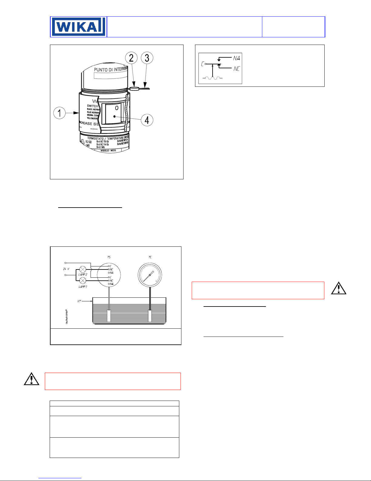
The position of the adjusting bush is given in Fig. 2.
Fig. 2 - Adjusting bush and plumbing
Adjustment slot cover
Sealing lead
Stainless steel wire
Adjusting bush
The effect of the sense of rotation of the adjusting bush is shown
on the slot cover. Rotate the bush by inserting a 3mm dia. rod or
drill into the holes on the bush itself (It recommends using a drill
bit on the side of the shank).
7 - SET POINT CALIBRATION
In order to proceed with the calibration and the periodical
functional verification of the instrument a suitable calibration
circuit (Fig. 3) and of an adequate source of heat are required.
The test instrument should have a measurement range
approximately equal to or slightly wider than the pressure switch
range and should have an accuracy consistent with the accuracy
required to calibrate the set point.
Fig. 3 – Calibration circuit
TS - Temperature switch
TT - Test thermometer
TB - Thermostatic bath
7.1 PRELIMINARY OPERATIONS
Slide up the adjustment cover (Fig. 2 item 1).
7.2 CALIBRATION CIRCUIT AND OPERATIONS
Prepare the control circuit as indicated in Fig.3
If the instrument is equipped with two contacts, remember that
they are released simultaneously but within the specification
tolerance.
The warning lamps should be connected to the terminals NA or
NC according to the required contact action.
Fig. 4 – Color of wires and function
GDN-Internal grounding connection: color jellow/green
C-Common: color brown
NO-Normally open: color blue
NC-Normally closed: color black
C-Common: color gray
NO-Normally open: color red
NC-Normally closed: color white
.
INSTRUCTION MANUAL
NI-492WE
Rev.4 05/18
Contacts status at atmospheric pressure.
C - Common
NA - Normally open
NC - Normally closed
Connection between C and NA
• If the circuit is open at the workin temperature, the instrument
closes the circuit when the set point is reached with temperature
on rise (closure on rise).
• If the circuit is closed at the working temperature, the instrument
opens the circuit when the set point is reached with temperature
on fall (opening on fall).
Connection between C and NC
• If the circuit is closed at the working temperature, the instrument
opens the circuit when the set point is reached with temperature
on rise (opening on rise).
• If the circuit is open at the working temperature, the instrument
closes the circuit when the set point is reached with temperature
on fall (closure on fall).
The temperature switch must be kept in the normal installation
position, i.e. with the temperature connection downwards.
Modify the temperature in the circuit up to the desired
microswitch set point value.
Using a 3mm dia. rod drill into the holes on the bush (It
recommends using a drill bit on the side of the shank).
Adjust its position until the relative lamp turns on (or turns off);
then turn it in the opposite direction until the lamp turns off (or
on). Slowly turn the bush again until the lamp turns on (or off)
7.3 SET POINT VERIFICATION
Increase the temperature up to the normal working temperature
(Tw), wait the stabilization of the temperature. Modify, slowly the
temperature up to the set value (Ti) and record the set point
value. Write the set point value on the adhesive label.
Note: the verification of the repeatability have to be tested
checking the set point (Ti) three times approaching the set point
from the same starting point (Tw). The temperature cycles have
to be performed slowly.
7.4 FINAL OPERATIONS
Disconnect the instrument from the calibration circuit.
Close the adjustment slot by sliding down the slot cover (Fig. 2,
1), then seal with lead the instrument.
Mount on pressure connection the protecting cap supplied with
the instrument. It should be definitively removed only during the
connection steps.
8 - INSTRUMENT PLUMBING
The plumbing (see Fig. 2), aimed as a guarantee against
possible tampering of the calibration, can be carried out using a
flexible steel wire (2), 1 mm
case in the groove purposely provided.
9 - MOUNTING AND CONNECTIONS
9.1 MOUNTING
Mount instruments with capillary either on pipe or surface by
means of the proper bracket (see Fig. 9 and 10) or direct on plant.
Select a location where possible shocks and temperature
variations remain within tolerable limits.
For the instrument with capillary the difference in height between
bulb and case have not exceeding two meters (fig 11 and 12
distance h).
9.2 INSTALLATION OF TEMPERATURE SWITCH
WITH DIFFERENCE IN HEIGHT BETWEEN BULB
AND INSTRUMENT ENCLOSURE GREATER THAN 2
METERS
Micro 1
9.2.1 TEMPERATURE SWITCHES CLASS SAMA II A
Difference in height between bulb and instrument enclosure
causes a systematic error of set point calibrated value (“bulb
elevation error”). This error can be corrected during calibration
using the table attached to our technical instruction IS-TC.401E,
available on request.
Micro 2
2
in section, wound up around the
3 of 7
 Loading...