

Page 1

Operating instructions
操作说明
GB
CN
GDT-20和GDHT-20型传感器
GDT-20型 GDHT-20型
Transmitter, models GDT-20, GDHT-20
Page 2

2 威卡 (WIKA) GDT20/GDHT20型传感器的操作说明
GB
CN
© 2013 WIKA Alexander Wiegand SE & Co. KG
All rights reserved. / 版权所有。
WIKA® is a registered trademark in various countries.
WIKA® 是威卡 (WIKA) 在全球多个国家的注册商标。
Prior to starting any work, read the operating instructions!
Keep for later use!
在开始作业前,请详细阅读本操作说明!
妥善保管好本文件,留待后用!
Transmitter, models GDT-20, GDHT-20 Page 25 - 46
GDT-20和GDHT-20型传感器 P3 – P24
14063434.01 04/2015 EN/DE
Page 3

3威卡 (WIKA) GDT20/GDHT20型传感器的操作说明
CN
4
5
8
9
9
10
19
20
21
22
23
目录
目录
目录
1. 简介
2. 安全性
规格
3.
4. 设计和功能
5. 运输、包装和储存
6. 试运行和运行
7. 维护与清洁
8. 故障
9. 拆卸、返修和废弃
附录1
附录2:EC符合性声明,GDT-20
:露点准确度
24
附录3:EC符合性声明,GDHT-20
关于符合性声明,请登录www.wika.com查阅
14063434.01 04/2015 EN/DE
Page 4

4
CN
1. 简介
1. 简介
- 网址: www.wika.cn/www.wika.com
- 相关数据资料: SP 60.09(GDT-20型)和SP 60.1(GDHT-20型)
- 应用顾问: 电话:+86 6878 8000
传真:+86 6878 0300
info@wika.cn
■ 本操作说明所提及的传感器均采用最先进技术进行设计和制造,且所有部件在生产过程中
均符合严格的质量和环境标准。我们的管理系统经过ISO 9001和ISO 14001认证。
■ 这些操作说明包含了关于仪表操作的重要信息。操作时,必须严格遵守所有安全提示和工
作指导,以确保安全。
■ 请严格遵守所在国家的相关事故预防条例以及关于仪表使用范围的一般安全规程。
■ 操作说明是产品的组成部分,必须置于仪表附近,并确保其可由熟练技术人员随时轻松取
阅。
■ 在开始作业前,熟练技术人员必须详细阅读并理解操作说明。
■ 对于因未将产品用于指定用途、不遵守相关操作说明、指派资质不全的技术人员或未经授
权对仪表进行改装而造成的产品损坏,制造商不承担任何责任。
■ 销售文件中所包含的一般性条款和条件也应适用。
■ 可能随时进行技术改动。
■ 其他资料:
威卡 (WIKA) GDT20/GDHT20型传感器的操作说明
14063434.01 04/2015 EN/DE
Page 5
5
1. 简介/2. 安全性
符号说明
警告!
…表示潜在危险情况,如未避免则可能导致严重伤害甚至死亡。
注意!
…表示潜在危险情况,如未避免则可能导致轻微伤害、设备损坏或环境危害。
提示
…提供实用窍门、建议以及实施高效而无故障的操作所需的信息。
2. 安全性
警告!
可在该操作说明的单独章节中找到其他重要的安全提示。
2.1 指定用途
在安装、试运行和运行之前,请确保所选择的传感器的测量范围、设计和具体测
量条件都符合应用要求。
否则可能造成严重人员伤害和/或设备损坏。
这些传感器设计用于填充有SF
6
气体的系统中,可以固定测量压力、温度和湿度(仅限
GDHT-20型)等状态变量。传感器可根据测量值计算出SF
6
气体的密度和露点/霜点等信息,
以对系统状态进行评估(仅限GDHT-20型)。此外,传感器支持MODBUS协议,可通过
RS-485接口读取所有参数。鉴于此,GDT-20或GDHT-20型传感器可用于固定监测SF6气罐中
的指定状态参数。
仪表严格按照上述用途设计和建造,因此只可用于这些用途。
必须严格遵守操作说明中包含的技术规格。一旦仪表出现了技术规格范围之外的错误处理或操
作,应立即停止使用仪表,并邀请经过授权的威卡 (WIKA) 检修工程师进行检查。
如果产品未按指定用途使用而造成损坏,制造商不承担任何责任。
威卡 (WIKA) GDT20/GDHT20型传感器的操作说明
CN
14063434.01 04/2015 EN/DE
Page 6

6
2. 安全性
2.2 人员资质
警告!
熟练技术人员
2.3 用于开关柜中的安全说明
警告!
关于SF
6
气体的有效标准和规范
安装、装配和试运行:
运行过程中的泄漏:
人员资质不够可能会导致人员伤害!
处理不当会导致相当严重的人员伤害和设备损坏。
■ 操作说明中所述的所有活动都只能由具备以下资质的熟练技术人员实施。
■ 无资质人员请远离危险区域。
熟练技术人员指的是经过技术培训、理解测量和控制技术以及对国内法规、当前标准和指令具
有相关经验和知识的技术人员。这些人员具有实施所述工作的能力,并且能够独立辨别潜在的
危险。
特殊工作条件(如腐蚀性介质)需要其他相关知识。
卸下来的传感器中所残留的介质会对人员、环境和设备造成危害,因此必须采取
充分的预防性措施。
发生故障时可能会泄漏腐蚀性介质。
■ BGI 753(德国SF
6
装置和设备标准)
■ IEC 61634(SF
6
气体转移)
■ IEC 60376(新SF
6
气体、工业级SF6气体)
■ IEC 60480(使用过的SF
6
气体)
■ CIGRE(国际大电网会议)276号报告,2005(SF
6
气体转移实用指南)
■ IEC 60376(新SF
6
气体、工业级SF6气体)
■ IEC 60480(使用过的SF
6
气体)
■ CIGRE 2002(“应用于电气行业的SF
6
气体”)
设备操作员必须确保只能由具备资质的公司或个人(即按照IEC 61634标准第4.3.1节或IEC
60840标准第10.3.1节进行过专门培训)转移SF
6
气体。
威卡 (WIKA) GDT20/GDHT20型传感器的操作说明
CN
14063434.01 04/2015 EN/DE
Page 7

7
2. 安全性
维修与维护:
■ IEC 61634(高压开关柜和控制柜中SF
6
气体的使用和转移)
■ CIGRE 1991(SF
6
气体转移)
■ CIGRE 276号报告,2005(SF
6
气体转移实用指南)
■ CIGRE 163号报告,2000(SF
6
气体混合物转移说明)
2.4 标签和安全标志
GDT-20产品标签
GDHT-20产品标签
符号说明
在仪表安装和试运行之前,请通读所有操作说明!
CE,欧洲共同体
贴有该标志的仪表符合相关的欧洲指令。
GDT-20
P#
S#
Pressure: 0 ...1.6 MPa abs
Temp.: -40 °C ... +80 °C
Density: 0 ... 60 g/l
MODBUS RTU
17 ... 30 VDC, Pmax. = 3 W
Made in Germany www.wika.com
Pin Function Comment
1 C RS485 common
2 U
B
17-30 VDC
3 GND
接地
4 A RS485
5 B RS485
13C
P# 产品编号
S# 序列号
压力测量范围
温度测量范围
密度测量范围
通信协议
电源
引脚分配
GDHT-20
P#
S#
Pressure: 0 ...1.6 MPa abs
Temp.: -40 °C ... +80 °C
Density: 0 ... 60 g/l
Dew point: -60 °C ... +20 °C
MODBUS RTU
17 ... 30 VDC, Pmax. = 3 W
Made in Germany www.wika.com
Pin Function Comment
1 C RS485 common
2 U
B
17-30 VDC
3 GND
4 A RS485
5 B RS485
13C
P# 产品编号
S# 序列号
压力测量范围
温度测量范围
密度测量范围
露点测量范围
通信协议
电源
引脚分配
SF6是一种无色无味、化学性质温和且不可燃的惰性气体,密度约是空气的5倍,对臭氧层无
毒无害。更多详细说明,请参见IEC 60376 和IEC 61634。
威卡 (WIKA) GDT20/GDHT20型传感器的操作说明
CN
14063434.01 04/2015 EN/DE
接地
Page 8

8
3. 规格
3. 规格
测量范围
露点: -50 ... +30 °C(仅限GDHT-20)
密度
1)
:
0 ... 60 g/升(20 °C时绝压为0.887 MPa)
温度: -40 ... +80 °C(可选-60 °C)
压力: 0 ... 1.6MPa(绝压)
爆裂压力: 5.2MPa(绝压)
过压限值: 高达3 MPa(绝压)
压力参考: 绝对压力
容许温度范围
1) 在对混合气体进行计算时,先要配置好压力条件。
工作温度: -40 ... +80 °C(可选-60 °C)(-40 ... +176 °F)
储存温度: -40 ... +80 °C(可选-60 °C) (-40 ... +176 °F)
电源U
B
DC 17 ... 30 V
功耗
GDT-20:最大为0.5 W
GDHT-20:最大为3 W
电气连接
M12 x 1圆形接头(5针)
配备RS-485接口,支持MODBUS® RTU通信
防护等级
IP 65(必须插入并使用具有相应防护等级的匹配接头)
重量
约0.40 kg
EMC指令
2004/108/EC,EN 61326电磁发射(1组,B类)和电磁抗扰度(工业应用)
EMC测试
■
抗干扰度符合IEC61000-4-3: 30V/m (80 MHz...2.7 GHz)
■
ESD(静电放电)符合 IEC 61000-4-2: 8kV/15kV, 接触放电/空气放电
■
瞬时抗干扰度符合IEC6100-4-4:4 kV
威卡 (WIKA) GDT20/GDHT20型传感器的操作说明
CN
14063434.01 04/2015 EN/DE
Page 9

9
3. ... / 4. 设计和功能 / 5. 运输、包装和...
■
脉冲电压符合IEC 61000-4-5标准:
GDT-20:2 kV(导线对地)和1 kV(导线间)
GDHT-20:1 kV(导线对地)和1 kV(导线间)
■
高频场抗扰度符合IEC 61000-4-6标准:
GDT-20:10 V
GDHT-20:3 V
更多其他规格参数,请参见威卡 (WIKA) 数据资料SP 60.09 (GDT-20)、SP 60.14 (GDHT-20)
以及订单文件。
对于特殊型号,请仔细查看送货单上所规定的规格参数。
4. 设计与功能
4.1 型号说明
4.2 交货范围
请在交货单上打勾确认各项交货内容。
5. 运输、包装和储存
5.1 运输
检查传感器是否有任何因运输而造成的损坏。
如有明显损坏,请立即报告。
5.2 包装
在安装之前请勿拆开包装。
保持原有包装,以便在运输过程中(如变更安装场所、发回厂家维修时)提供最佳的保护。
所述传感器配有压力、温度和湿度(仅限GDHT-20型)传感器,并集成微处理器电路,可依
据相应算法由测得的参数计算出SF
6
气体密度和湿度(仅限GDHT-20型)等状态参数。
威卡 (WIKA) GDT20/GDHT20型传感器的操作说明
CN
14063434.01 04/2015 EN/DE
Page 10
10
5. 运输、包装和储存
5.3 储存
储存场所的容许条件:
■
温度:-40 ... +80 °C(可选-60 °C)
■
湿度:90%相对湿度(无冷凝)
避免直接暴露在下列环境中:
■
日光直射或接近高温物体
■
机械振动和冲击(猛地放下)
■
含油烟、蒸汽、粉尘和腐蚀性气体的环境
■
潜在爆炸性环境、易燃气体环境
请将传感器置于其原始包装内,并放置到满足上述条件的地方。
警告!
6. 试运行和运行
6.1 机械安装
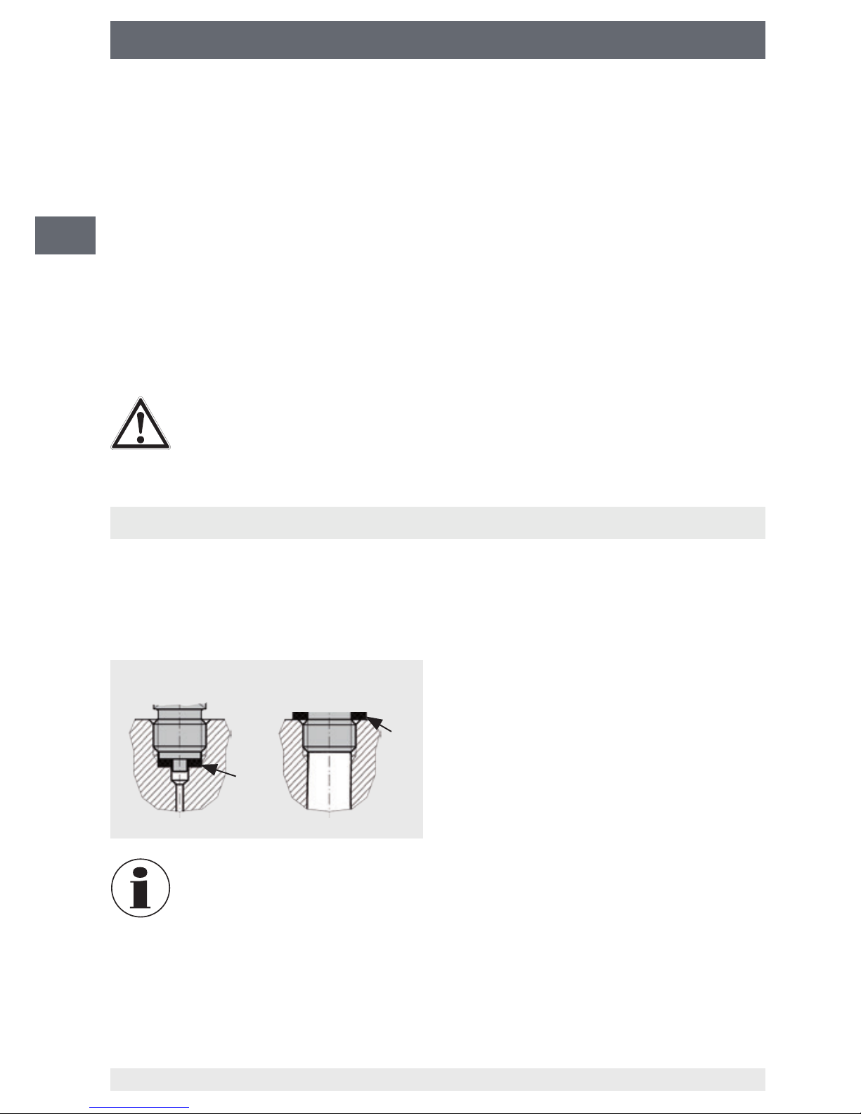
6.1.1 密封过程连接
直螺纹
符合EN 837标准
符合DIN 3869标准
GDT-20型 GDHT-20型
在储存仪表之前(运行之后),请除去所有残留介质。尤其当介质对健康有害
(如苛性物质、有毒、致癌和放射性物质等)时,这一点非常重要。
必须使用适当的平垫圈、密封环或威卡 (WIKA) 成形密封垫在密封面处①对直螺纹过程连接进
行适当密封。
在安装GDHT-20型传感器时,环境中的少量湿气会不可避免地进入测量元件内。
因此,需要经过一段时间才能达到非常干燥的无流动气室所得到的正确测量结果
(实际时间依具体应用而定,此环节大约需要数天)。
测量点最好直接设置在气室处,因此设置在测量线路末端可能无法得到最佳结果
(影响因素主要有温度变化以及主罐中无法实现水分平衡等)。
威卡 (WIKA) GDT20/GDHT20型传感器的操作说明
CN
14063434.01 04/2015 EN/DE
Page 11
11
6. 试运行和运行
6.1.2 使用转接头和腔体进行安装
注意!
可用转接头和/或腔体的过程连接应正确密封并连接到测量点。
6.1.3 安装传感器
6.2 电气安装
警告!
6.2.1 连接组件
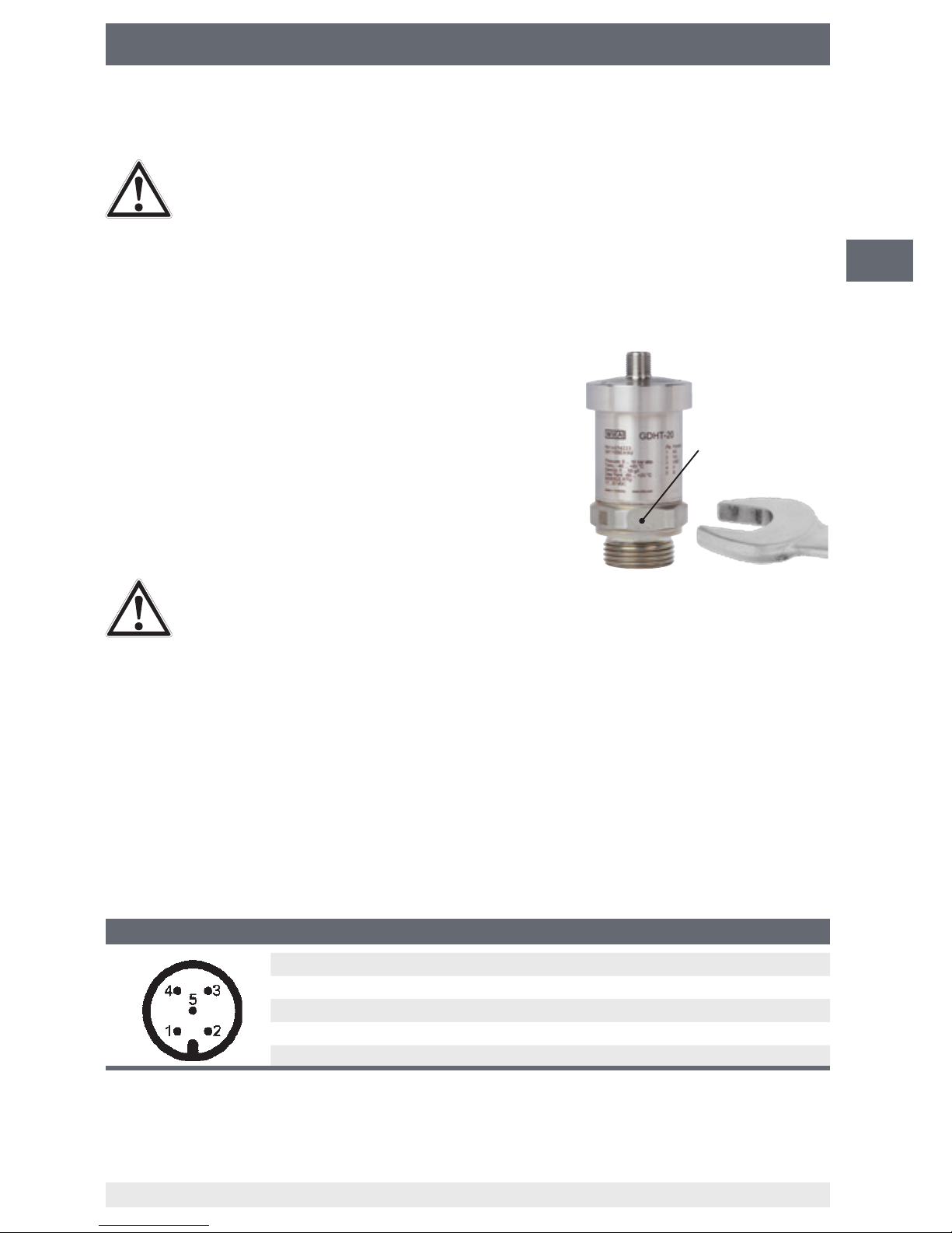
6.2.2 引脚分配
M12x1圆形接头(5针)
1 C RS-485共地端的参考电位
2 U
B
电源
3 GND 接地
4 A 信号RS-485
5 B 信号RS-485
扳手槽
GDHT-20型配备的转接头或腔体(如果有的话)在出厂前已完全装配好,并且经
过全面的密封测试。如果强行拆卸,会损害测量组件的气密密封性并导致其无法
使用!
■ 拧入传感器时,千万不可通过外壳施力,必须使用适
当的工具通过特制的扳手槽施力。拧紧力矩最大不超
过60 Nm。
■ 拧紧时切勿错扣螺纹。
仪表屏蔽线的功能只是屏蔽仪表电磁干扰,不能为人员提供保护。
■ 所使用的电缆应包含屏蔽双绞数据线且满足特定工作条件所需特性。
■ 电缆直径应与插头电缆密封套相匹配,并确保已安装插头的电缆密封套紧密配合且密封件
完好无损。为确保达到相应的防护等级,必须上紧螺纹连接并检查密封件已正确就位
■ 确保没有湿气从电缆端进入。
威卡 (WIKA) GDT20/GDHT20型传感器的操作说明
CN
14063434.01 04/2015 EN/DE
Page 12

12
6. 试运行和运行
6.2.3 RS-485
6.3 MODBUS
®
6.4 MODBUS®启动工具
■
电源单元
■
接口转换器(RS-485转USB)
■
A型-B型USB电缆
■
带M12x1接头的传感器电缆
■
6.4.1 连接到电脑
RS-485
USB
+
-
接口转换器
电源
用于实现MODBUS
®
协议的物理层是符合EIA/TIA-485标准的RS-485串行接口。因此,引脚4
和5(A和B)之间的差分信号需要使用一个两线式系统进行处理(半双工)。这两路信号的共
地端参考电位在引脚1(C)上。
MODBUS
®
通信协议采用主/从结构。GDT-20和GDHT-20型传感器支持通信协议为MODBUS®
RTU,可通过一个两线式RS-485接口实现串行数据传输。
MODBUS
®
协议是一种单主机协议。主设备对所有数据进行控制,并监控任何可能出现的超时
(没有来自寻址传感器的应答)。只有在收到主设备的请求时,所连接的传感器才会向其发送
报文。
MODBUS
®
RTU(RTU:远程终端单元)采用二进制传输数据,可确保良好的数据传输性能。
关于协议的详细说明,请参见www.modbus.org
带可选启动工具(订购编号14075896)的传感器可在测量点处进行配置并投入运行。
另外,传感器还可集成数据记录仪,能显示指定周期内的测量数据或将数据写入一个文件中。
启动工具包括:
GDM-100-TI的转换电缆
■
储存在U盘上的MODBUS
®
工具(也可从www.wika.com/sf6下载)
威卡 (WIKA) GDT20/GDHT20型传感器的操作说明
CN
14063434.01 04/2015 EN/DE
Page 13
13
6. 试运行和运行
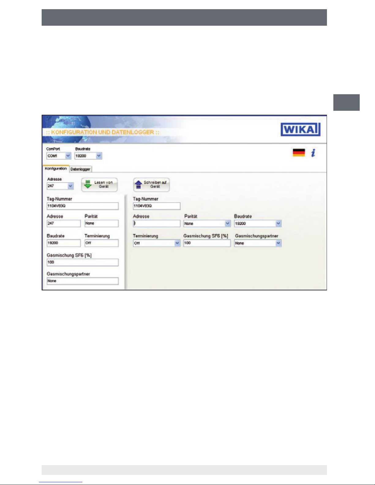
6.4.2 MODBUS®工具
在完成接线和安装接口转换器软件(或复制MODBUS®工具软件)之后,便可以启动该应用程序。
系统要求
Microsoft® Windows® 7(32位)或Windows® XP(32位)操作系统
Windows是微软公司在美国及其他国家的注册商标。
6.4.2.1 出厂设置
出厂设置
■
标签编号:威卡 (WIKA)
■
地址:247
■
波特率:19,200
■
奇偶校验:无
■
■
混合气体中SF6气体的百分比[%]:100%
调度:关闭
■
混合气体:N
2
PC机上的COM端口已被设置用于访问传感器。默认设置地址为247,波特率为19200。通过
这些设置,可以通过““download from device(从仪器下载)”按钮来读取传感器的数据。
威卡 (WIKA) GDT20/GDHT20型传感器的操作说明
CN
14063434.01 04/2015 EN/DE
Page 14
14
6. 试运行和运行
6.4.2.2 写入新参数
在写入之前请将新的通信参数记录下来,因为在重新访问传感器时还会用到这些参数。
将新参数值写到正确的字段内【在“upload to device(上传至仪器)”按钮下方】。
名称 有效值
标签编号(传感器名称) 16字符(以ASCII码表示)
地址 1 ... 247
波特率 1.200 ... 115.200
奇偶校验 无,偶校验
调度 Off(关),On(开)
混合气体中SF
6
气体的百分比[%] 0 ... 100
混合气体 N
2
和CF
4
-
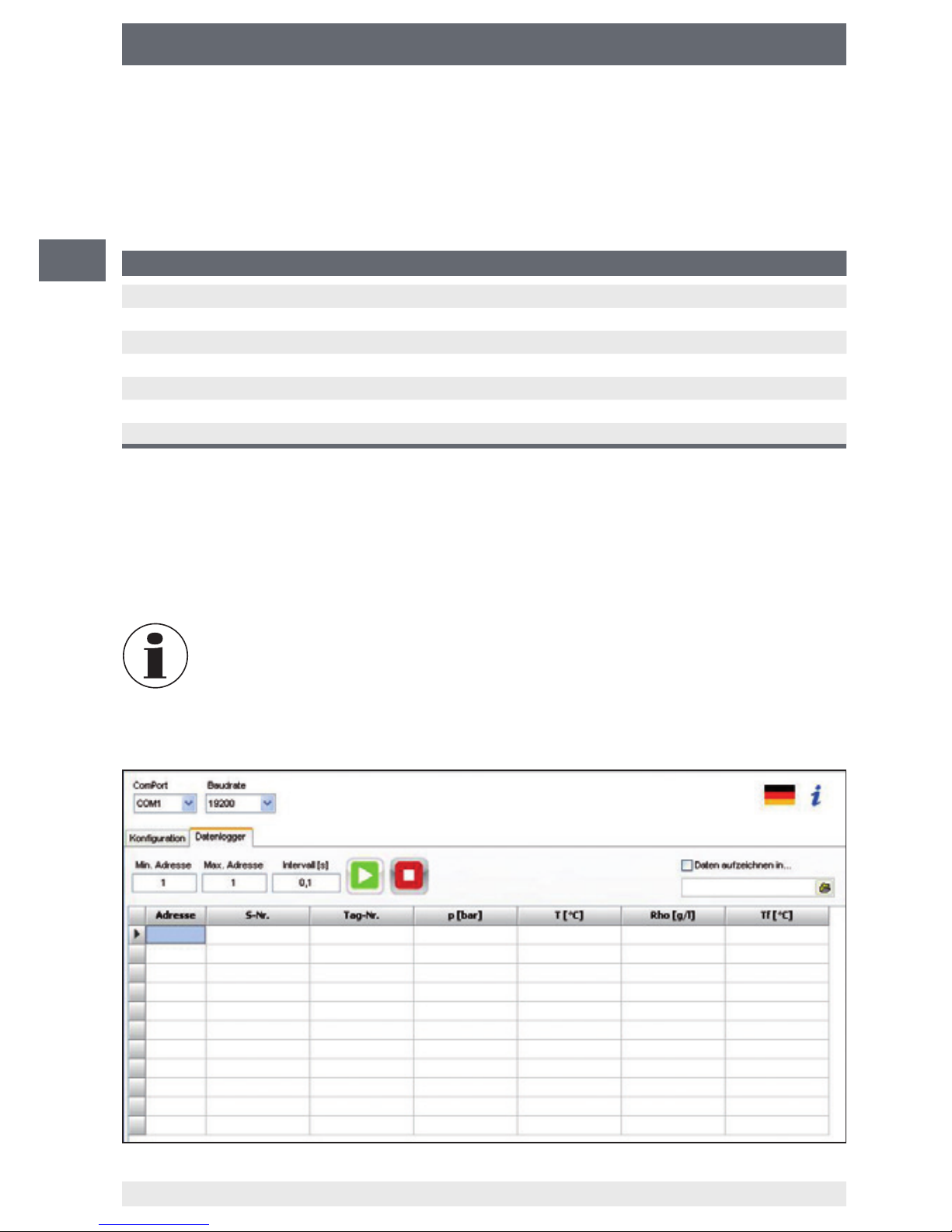
6.4.2.3 数据记录仪
数据记录仪可记录在固定时间段内的测量值。
按下“upload to device(上传至仪器)”按钮可将相应字段中的数据传送到传感器寄存器。
在传输参数后将电源断开再重新接通即可完成写入操作。
在后续读取操作期间,所输入的数据将会显示在左侧。
如果在非拉丁字符集(如中文)环境下使用Windows
®
,则控制面板中的区域设置
必须改为“English (USA)(美国英语)”,否则可能会发生通信错误。
威卡 (WIKA) GDT20/GDHT20型传感器的操作说明
CN
14063434.01 04/2015 EN/DE
Page 15

15
6. 试运行和运行
6.4.2.4 MODBUS®寄存器和功能说明
■
MODBUS应用协议规范
串行线路MODBUS规范和实施指南
■
寄存器结构如下所述。
通过信息进行通信
信息的一般形式
仪表地址 功能 数据 CRC校验1
8位 8位 n x 8位 16位
典型传输示例:
间歇 信息1
►
间歇 信息2
►
间歇 信息3 ...
有效功能调用
名称 说明
03 读取保持寄存器 读取一个或多个寄存器值或仪表配置
04 读取输入寄存器
06 写入单个寄存器
读取一个寄存器值或仪表配置
写入一个寄存器值或仪表配置
16 写入多个寄存器 写入一个或多个寄存器值或仪表配置
08 诊断-子代码00 诊断功能
23 读/写多个寄存器配置 写入或读取一个/数个寄存器值或仪表配置
在设置好COM端口、波特率和最小/最大地址或时间间隔之后,就可以开始记录了。对于连续
记录应用,可以按指定的时间间隔记录测量数据(时间间隔定义在一个以制表符分割的文本文
件中)。
绿色启动标志用于开始记录,红色停止标志用于停止记录。
建议参考以下文件(可从www.modbus.org下载),以理解接下来各章将要提到的MODBUS
®
结构。
根据MODBUS
®
规范的规定,每条信息之间必须使用至少3.5个字符隔开。
单个信息内的字符之间不得有超过1.5个字符的间隔。
威卡 (WIKA) GDT20/GDHT20型传感器的操作说明
CN
14063434.01 04/2015 EN/DE
Page 16

16
6. 试运行和运行
6.4.2.5 数据寄存器和测量值
测量数据只能读取,无法写入。
GDT-20, GDHT-20型
寄存器 测量参数 测量参数 单位 测量条件
00000 压力 p bar
00002 压力 p MPa
00004 压力 p Pa
00006 压力 p kPa
00008 压力 p psi
00010 压力 p N/cm²
00012 温度 T °C
00014 温度 T K
00016 温度 T °F
00018 气体密度 rho g/l
00020 气体密度 rho kg/m³
00022 20 °C条件下的标准压力 p20 bar 20 °C条件下的压力
GDHT-20型
寄存器 测量参数 测量参数 单位 参考气体 测量条件
00024 湿度,霜点 T
f
°C SF
6
大气压
00026 湿度,露点 T
d
°C SF
6
大气压
00028 湿度,霜点 T
f
°C SF
6
气室压力
00030 湿度,露点 T
d
°C SF
6
气室压力
00032 湿度,霜点 T
f
°C N
2
大气压
00034 湿度,露点 T
d
°C N
2
大气压
00036 湿度,霜点 T
f
°C N
2
气室压力
00038 湿度,露点 T
d
°C N
2
气室压力
00040 含水量(体积百分比) ppm
v
- SF
6 -
00042 含水量(质量百分比) ppm
v
- SF
6 -
00044 含水量(体积百分比) ppm
v
- N
2 -
00046 含水量(质量百分比) ppm
v
- N
2 -
00048 相对湿度 rH % - -
数据采用32位浮点数表示(低位字在前),符合IEEE 754-1985标准关于IEEE单精度32位浮
点型数据的规定。
威卡 (WIKA) GDT20/GDHT20型传感器的操作说明
CN
14063434.01 04/2015 EN/DE
Page 17

17
6. 试运行和运行
6.4.2.6 配置
寄存器 参数 取值范围 预设值 是否可写入
00100 地址 1 ... 247 247 是
00101 波特率 1.200 ... 115.200 19.200 是
00102 奇偶校验 无,偶校验 None 是
00103 端接 Off(关),On(开) Off(关) 是
00104
混合气体中SF6气体的百分比[%]
0 ... 100% 100 % 是
00105 混合气体 N2和CF4 N2 是
00106 序列号 只读
00110 硬件版本 只读
00111 软件版本 只读
00112 指定型号 0 = GDT-20
1 = GDHT-20
只读
00113 标签编号(传感器名称) 16位ASCII编码 是
地址
可用地址为1…247(预设值为247)
波特率
不同的波特率以0…8寄存器值表示。
波特率 寄存器值
1.200 0
2.400 1
4.800 2
9.600 3
14.400 4
19.200 5(预设值)
38.400 6
57.600 7
115.200 8
奇偶校验
奇偶校验 寄存器值
无 0(预设值)
偶校验 1
威卡 (WIKA) GDT20/GDHT20型传感器的操作说明
CN
14063434.01 04/2015 EN/DE
Page 18

18
6. 试运行和运行
端接
通过寄存器配置可以启用一个120Ω的端接电阻。
端接 寄存器值
0(预设值)Off(关)
On(开) 1
混合气体中SF6气体的百分比[%]
SF6在气体混合物中的百分比能以0…100%之间的数值表示。
混合气体中SF6气体
的百分比[%]
寄存器值
0 ... 100 % 0 ... 100(预设值为100)
混合气体
预设的混合气体为“N2”。
混合气体 寄存器值
N
2
0(预设值)
CF
4
1
标签编号
此处可输入一个最多16位字符的传感器名称。
6.4.2.7 状态寄存器
寄存器功能 功能 是否可写入
00200 错误存储 16位(参见下表) 只读
00201 复位错误存储 写入0x0001 是
00202 软件复位 写入0x0001 是
00203 恢复到出厂设置 写入0x0001 是
00204 启动加热过程(仅限GDHT-20型) 写入0x0001 是
取值范围(触发功能)
错误存储在重启(断开电源)后将会复位。向寄存器地址00201写入0x0001具有同样的效果。
威卡 (WIKA) GDT20/GDHT20型传感器的操作说明
CN
14063434.01 04/2015 EN/DE
Page 19

19
6. 试运行和运行/7. 维护与清洁
错误存储说明
位 说明
C 压力信号低于下限 (< 0 MPa)
1 压力信号超出上限 (< 1.6 MPa)
2 压力传感器故障
3 温度信号低于下限 (< -40 °C)(可选-60 °C)
4 温度信号超出上限 (< 80 °C)
5 压力/温度传感器通信错误
6
压力密度低于下限(SF6气体液化)
7 气体密度超出上限 (> 80 g/l)
8 湿度传感器故障(仅限GDHT-20型)
9 湿度传感器通信错误(仅限GDHT-20型)
10 重复发生MODBUS
®
通信错误
示例:0x0082
如果设置了第1和第7位,则会超出压力和气体密度上限。
软件复位
恢复到出厂设置
启动加热过程(仅限GDHT-20型)
7. 维护与清洁
7.1 维护
传感器无需维护。
维修工作必须由制造商完成。
向寄存器203写入0x0001将会导致传感器恢复到出厂设置,并执行一次软件复位。此后,所有
可写入的寄存器都将复位到其初始设置。
向寄存器204写入0x0001将会导致湿度传感器执行手动烘干。GDHT-20型会在上次加热过程
完成后间隔30分钟自动进行加热。如需更短的时间间隔,则需手动写入寄存器,最短时间间隔
为10分钟。
向寄存器202写入0x0001将会导致软件复位。复位后所有更改过的参数将会立即生效(如改
变地址等)。
威卡 (WIKA) GDT20/GDHT20型传感器的操作说明
CN
14063434.01 04/2015 EN/DE
Page 20

20
7. 维护与清洁/8. 故障
7.2 清洁
注意!
关于仪表返修的信息,请参见第9.2节“返修”。
8. 故障
一旦出现故障,首先要检查传感器的机械和电气安装是否正确。
故障 原因 采取措施
气体密度稳步减小 气室发生泄漏 控制传感器的机械装配
使用泄漏探测器(如GIR-10)找出
泄漏点
没有MODBUS通信 电气连接错误 检查接线和电源
通过威卡 (WIKA) 启动工具进行查询
湿度过高,但有逐渐干燥
的趋势
仪表安装后的典型时间响应 测量值将会逐渐稳定,详情请参见
第6.1节
注意!
■ 在进行清洁操作之前,请正确将传感器从压力源断开,然后关闭并切断电
源。
■ 使用湿布对传感器进行清洁。
■ 清洁时,切勿使电气连接进水。
■ 对于拆卸开的仪表,在返修之前应进行清洗或清洁,以避免人员和环境接触
到残留介质。
■ 已拆卸传感器中的残留介质可能会对人、环境和设备造成危害,因此应采取
充分的预防措施。
■ 在清洁时请勿使用任何尖锐或坚硬物体,以免对传感器造成损坏。
通过威卡 (WIKA) 启动工具进行查询
如果通过上述措施无法消除故障,则请立即关闭传感器,确保不再有压力和/或信
号,并确保传感器不会意外地再次运行。
在这种情况下,请与制造商取得联系。
如果需要返修,请遵循第9.2节“返修”所给出的相关说明。
威卡 (WIKA) GDT20/GDHT20型传感器的操作说明
CN
14063434.01 04/2015 EN/DE
Page 21

21
9. 拆卸、返修和废弃
9. 拆卸、返修和废弃
警告!
9.1 拆卸
9.2 返修
警告!
9.3 废弃
已拆卸传感器中的残留介质会对人、环境和设备造成危害。
必须采取充分的预防措施。
在拆卸传感器时,千万不可通过外壳施力,必须要使用适当的工具通过专门提供的扳手槽施力
(详情请参见第6.1.3节“安装传感器”)。
只有在系统已泄压的情况下才可将传感器断开!
传感器返修时请使用其原始包装或适当的运输包装。
运送仪表时请严格遵守以下要求:
交给威卡 (WIKA) 的所有传感器切勿包含任何有害物质(酸、碱和溶液等)。
关于返修的更多信息,请查阅我们的网站上“Service(服务)”栏。
传感器必须按照相关要求正确废弃处理,以免对环境造成危害。
请以环保方式对仪表部件和包装材料进行废弃处理,并遵守所在国家的废弃物处理法规。
威卡 (WIKA) GDT20/GDHT20型传感器的操作说明
CN
14063434.01 04/2015 EN/DE
Page 22

22
附录1
威卡 (WIKA) GDT20/GDHT20型传感器的操作说明
CN
14063434.01 04/2015 EN/DE
:露点准确度
für kontinuierliche
Messungen ungeeignet
Genauigkeit
nicht spezifiziert
Gastemperatur t [°C]
Taupunkttemperatur td [°C]
-30 -20 -10 0 10 20 30 40 50 60 70 80
-40
-60
-50
-30
-20
-10
0
10
20
30
40
-40
-70
untere Grenzlinie
der Taupunktermittlung
Genauigkeit
± 3 K Taupunkt
不适用于连续测量
规定露点的下限值
露点准确度
为±3K
露点温度td [°C]
气体温度 [°C]
准确度不确定
Page 23

CN
23
附录2:EC符合性声明,GDT-20
威卡 (WIKA) GDT20/GDHT20型传感器的操作说明
14063434.01 04/2015 EN/DE
Page 24

24
附录3
威卡 (WIKA) GDT20/GDHT20型传感器的操作说明
CN
14063434.01 04/2015 EN/DE
:EC符合性声明,GDHT-20
Page 25

25
14063434.01 04/2015 EN/DE
WIKA operating instructions transmitter, models GDT-20, GDHT-20
EN
Contents
Contents
1. General information 26
2. Safety 27
3. 30
4. Design and function 31
5. Transport, packaging and storage 31
6. Commissioning, operation 32
7. Maintenance and cleaning 41
8. Faults 42
9. Dismounting, return and disposal 43
Appendix 1: Accuracy of the dew point 44
Appendix 2: EC declaration of conformity, model GDT-20 45
Appendix 3: EC declaration of conformity, model GDHT-20 46
Declarations of conformity can be found online at www.wika.com
Page 26

26 WIKA operating instructions transmitter, models GDT-20, GDHT-20
14063434.01 04/2015 EN/DE
EN
1. General information
1. General information
■
The transmitter described in the operating instructions has been designed and manufactured using state-of-the-art technology. All components are subject to stringent quality
ISO 9001 and ISO 14001.
■
These operating instructions contain important information on handling the instrument.
Working safely requires that all safety instructions and work instructions are observed.
■
Observe the relevant local accident prevention regulations and general safety regulations
for the instrument's range of use.
■
The operating instructions are part of the product and must be kept in the immediate
vicinity of the instrument and readily accessible to skilled personnel at any time.
■
Skilled personnel must have carefully read and understood the operating instructions prior
to beginning any work.
■
The manufacturer's liability is void in the case of any damage caused by using the product
contrary to its intended use, non-compliance with these operating instructions, assignment
■
The general terms and conditions contained in the sales documentation shall apply.
■
■
Further information:
- Internet address: www.wika.de / www.wika.com
- Corresponding data sheets: SP 60.09 (model GDT-20), SP 60.14 (model GDHT-20)
- Application consultant: Tel.: +49 9372 132-8971
Fax: +49 9372 132-8008971
sf6-sales@wika.com
Page 27

27
14063434.01 04/2015 EN/DE
WIKA operating instructions transmitter, models GDT-20, GDHT-20
EN
1. General information / 2. Safety
Explanation of symbols
WARNING!
... indicates a potentially dangerous situation that can result in serious injury or
death, if not avoided.
CAUTION!
... indicates a potentially dangerous situation that can result in light injuries or
damage to equipment or the environment, if not avoided.
Information
trouble-free operation.
2. Safety
WARNING!
Before installation, commissioning and operation, ensure that the appropriate
tions, has been selected.
Non-observance can result in serious injury and/or damage to the equipment.
Further important safety instructions can be found in the individual chapters of
these operating instructions.
2.1 Intended use
These transmitters are designed for use at SF
6
pressure, temperature and humidity (only model GDHT-20) are measured permanently. From
these, the transmitter calculates the values gas density and dew point/frost point (only model
GDHT-20) information of the SF6 gas in order to evaluate the state of the system. All stated
parameters can be read from the Modbus protocol via the RS-485 interface. The model
GDT-20 or GDHT-20 transmitters are therefore used for permanently monitoring the stated
status parameters in SF6 gas tanks.
The instrument has been designed and built solely for the intended use described here, and
may only be used accordingly.
requires the instrument to be taken out of service immediately and inspected by an authorised
WIKA service engineer.
The manufacturer shall not be liable for claims of any type based on operation contrary to the
intended use.
Page 28

28 WIKA operating instructions transmitter, models GDT-20, GDHT-20
14063434.01 04/2015 EN/DE
EN
2. Safety
2.2 Personnel
WARNING!
Risk of injury should be
Improper handling can result in considerable injury and damage to equipment.
■
The activities described in these operating instructions may only be carried
■
Skilled personnel
Skilled personnel are understood to be personnel who, based on their technical training,
knowledge of measurement and control technology and on their experience and knowledge of
work described and independently recognising potential hazards.
Special operating conditions require further appropriate knowledge, i.e. of aggressive media.
2.3 Safety instructions for use in switchgear
WARNING!
Residual media in the dismounted transmitter can result in a risk to persons, the
environment and equipment.
Aggressive media may be present should a failure occur.
The plant operator must ensure that the handling of SF
6
IEC 61634, section 4.3.1 or IEC 60480, section 10.3.1.
Valid standards and guidelines for SF6 gas
Installation, assembly, commissioning:
■
BGI 753 (SF6 plant and equipment in Germany)
■
IEC 61634 (Handling of SF6 gas)
■
IEC 60376 (new SF6 gas, technical SF6 gas)
■
IEC 60480 (used SF6 gas)
■
CIGRE report 276, 2005 (Practical SF6 gas handling instructions)
Leaks during operation:
■
IEC 60376 (new SF6 gas, technical SF6 gas)
■
IEC 60480 (used SF6 gas)
■
CIGRE 2002 (“SF6 gas in the electrical industry”)
Page 29

29
14063434.01 04/2015 EN/DE
WIKA operating instructions transmitter, models GDT-20, GDHT-20
EN
2. Safety
Repair work and maintenance:
■
IEC 61634 (Use and handling of SF6 gas in high-voltage switchgear and control gear)
■
CIGRE 1991 (Handling of the SF6 gas)
■
CIGRE report 276, 2005 (Practical SF6 gas handling instructions)
■
CIGRE report 163, 2000 (Guide for SF6 gas mixtures)
SF
6
Detailed information is given in IEC 60376 and IEC 61634.
2.4 Labelling, safety marks
Product label GDT-20
Product label GDHT-20
Explanation of symbols
Before mounting and commissioning the instrument, ensure you read the
operating instructions!
CE, Communauté Européenne
Instruments bearing this mark comply with the relevant European directives.
GDT-20
P#
S#
Pressure: 0 ... 16 bar abs
Temp.: -40 °C ... +80 °C
Density: 0 ... 60 g/l
MODBUS RTU
17 ... 30 VDC, Pmax. = 3 W
Made in Germany www.wika.com
Pin Description
1 C RS-485 GND
2 U
B
17-30 VDC
3 GND Ground
4 A RS-485
5 B RS-485
13C
P# article number
S# serial number
Measuring range pressure
Measuring range temperature
Measuring range density
Communication protocol
Power supply
Pin assignment
GDHT-20
P#
S#
Pressure: 0 ... 16 bar abs
Temp.: -40 °C ... +80 °C
Density: 0 ... 60 g/l
Dew point: -60 °C ... +20 °C
MODBUS RTU
17 ... 30 VDC, Pmax. = 3 W
Made in Germany www.wika.com
Pin Description
1 C RS-485 GND
2 U
B
17-30 VDC
3 GND Ground
4 A RS-485
5 B RS-485
13C
P# article number
S# serial number
Measuring range pressure
Measuring range temperature
Measuring range density
Measuring range dew point
Communication protocol
Power supply
Pin assignment
Page 30

30 WIKA operating instructions transmitter, models GDT-20, GDHT-20
14063434.01 04/2015 EN/DE
EN
3.
3.
Measuring ranges
Dew point: -50 ... +20 °C (GDHT-20 only)
Density
1)
: 0 ... 60 g/litre (8.87 bar abs. at 20 °C)
Temperature: -40 ... +80 °C(option:<-60°C)
Pressure: 0 ... 16 bar abs.
Burst pressure: 52 bar abs.
Overpressure limit: up to 30 bar abs.
Pressure reference: Absolute
Permissible temperature ranges
Operating temperature: -40 ... +80 °C(option:<-60°C), -40 ... +176 °F
Storage temperature: -40 ... +80 °C(option:<-60°C), -40 ... +176 °F
Permissible humidity
≤ 90 % r. h. (non-condensing)
Voltage supply U
B
DC 17 ... 30 V
Power consumption
GDT-20: max. 0.5 W
GDHT-20: max. 3 W
Electrical connection
Circular connector M12 x 1 (5-pin)
Modbus RTU via RS-485 interface
Ingress protection
IP 65, only when plugged in and using mating connectors with the corresponding ingress
protection
Weight
approx. 0.40 kg
EMC directive
2004/108/EC, EN 61326 emission (group 1, class B) and interference immunity (industrial
application)
EMC tests
■
Interference immunity per IEC 61000-4-3: 30 V/m (80 MHz ... 2.7 GHz)
■
Burst per IEC 61000-4-4: 4 kV
■
ESD per IEC 61000-4-2: 8 kV/15 kV, contact/air
Page 31

31
14063434.01 04/2015 EN/DE
WIKA operating instructions transmitter, models GDT-20, GDHT-20
EN
3. ... / 4. Design and function / 5. Transport, packaging and ...
■
Impulse voltages per IEC 61000-4-5:
GDT-20: 2 kV conductor to ground, 1 kV conductor to conductor
GDT-20: 1 kV conductor to ground, 1 kV conductor to conductor
■
GDT-20: 10 V
GDHT-20: 3 V
the order documentation.
4. Design and function
4.1 Code designation
The described transmitters are equipped with sensors for pressure, temperature and
humidity (only GDHT-20). From this, the integrated microprocessor electronics calculate the
status parameters of SF6 gas for gas density and humidity (only GDHT-20) with the help of
algorithms.
4.2 Scope of delivery
Cross-check scope of delivery with delivery note.
5. Transport, packaging and storage
5.1 Transport
Check the transmitter for any damage that may have been caused by transport.
Obvious damage must be reported immediately.
5.2 Packaging
Do not remove packaging until just before mounting.
Keep the packaging as it will provide optimum protection during transport (e.g. change in
installation site, sending for repair).
Page 32

32 WIKA operating instructions transmitter, models GDT-20, GDHT-20
14063434.01 04/2015 EN/DE
EN
5. Transport, packaging and storage
5.3 Storage
Permissible conditions at the place of storage:
■
Storage temperature: -40 ... +80 °C(option:<-60°C)
■
Humidity: 90 % r. h. (no condensation)
Avoid exposure to the following factors:
■
Direct sunlight or proximity to hot objects
■
Mechanical vibration, mechanical shock (putting it down hard)
■
Soot, vapour, dust and corrosive gases
■
above.
WARNING!
Before storing the instrument (following operation), remove any residual media.
This is of particular importance if the medium is hazardous to health, e.g. caustic,
toxic, carcinogenic, radioactive, etc.
6. Commissioning, operation
6.1 Mechanical mounting
6.1.1 Sealing the process connection
Correct sealing of the process connections with parallel threads at the sealing face must be
By installing a GDHT-20, a small quantity of humidity from the atmosphere inevi-
very dry gas compartments will only become attained over time (depending on
the particular application, this may take several days).
The measuring point should preferably be positioned directly at the gas compartment. Measurement at the end of measuring lines prevents optimal results
Parallel threads
per EN 837
per DIN 3869
Model GDT-20 Model GDHT-20
Page 33

33
14063434.01 04/2015 EN/DE
WIKA operating instructions transmitter, models GDT-20, GDHT-20
EN
6. Commissioning, operation
6.1.2 Installation using an adapter and measuring chambers
CAUTION!
If the GDHT-20 is delivered with an adapter or measuring chamber, it is
completely mounted and tested for leak tightness in our company. Dismounting
compromises the leak tightness of the measuring assembly and renders it
unserviceable!
The process connections of the available adapters and/or measuring chambers are to be
properly sealed and connected to the measuring point.
6.1.3 Installing the instrument
■
When screwing the instrument in, the force required to
do this must not be applied through the case, but only
using a suitable tool. The torque should maximally be
60 Nm when screwing it in.
■
When screwing in, do not cross the threads.
6.2 Electrical mounting
WARNING!
The instrument shield does not act as a protective conductor for protection of
personnel, rather as a functional ground in order to shield the instrument from
6.2.1 Connection assembly
■
Use a cable consisting of shielded twisted pair data lines with suitable characteristics for
the particular operating conditions.
■
Select a cable diameter that matches the cable gland of the plug. Make sure that the cable
Tighten the threaded connection and check that the seal is correctly seated, in order to
ensure the ingress protection.
■
Make sure that no moisture enters at the cable end.
6.2.2 Pin assignment
Circular connector M12 x 1 (5-pin)
1 C Reference potential RS-485 common
2 U
B
Voltage supply
3 GND Ground
4 A Signal RS-485
5 B Signal RS-485
Page 34

34 WIKA operating instructions transmitter, models GDT-20, GDHT-20
14063434.01 04/2015 EN/DE
EN
6. Commissioning, operation
6.2.3 RS-485
The physical layer the for Modbus® protocol is the serial RS-485 interface per EIA/TIA-485.
system (half-duplex). The mutual reference potential for the signals is on pin 1 (C).
6.3 Modbus
The Modbus® communication protocol is based on a master/slave architecture. The protocol
implemented in the transmitters GDT-20 and GDHT-20 is Modbus® RTU with serial transmission via a 2-wire RS-485 interface.
The Modbus® protocol is a single-master protocol. This master controls the entire data and
monitors any possible timeouts (no reply from the addressed instrument). The connected
instruments may only send telegrams after request by means of the master.
Modbus® RTU (RTU: Remote Terminal Unit) transmits the data in binary form, guaranteeing a
good data throughput.
Detailed information on the protocol under www.Modbus.org
6.4 Modbus® startup kit
at the measuring point for operation.
The start-up kit consists of:
■
Power supply unit
■
Interface converter (RS-485 to USB)
■
USB cable type A to type B
■
Sensor cable with M12 x 1 connector
■
Adapter cable for GDM-100-TI
■
Modbus® tool on USB stick
6.4.1 Establish connection to the computer
RS-485
USB
+
-
Interface converter
Voltage supply
Page 35

35
14063434.01 04/2015 EN/DE
WIKA operating instructions transmitter, models GDT-20, GDHT-20
EN
6. Commissioning, operation
6.4.2 Modbus tool
After wiring and installing the software of the interface converter or copying the Modbus® tool
software, the program can be started.
System requirements
Microsoft® Windows® 7 (32-bit) or Windows® XP (32-bit)
Windows is a registered trademark of Microsoft Corporation in the United States and other countries.
6.4.2.1 Factory setting
The COM port allocated at the PC has to be set for the access to the transmitter. Upon
With these settings, the transmitters can be read via the button “download from device”.
Factory setting
■
Tag number: WIKA
■
Address: 247
■
Baud rate: 19,200
■
Parity: none
■
■
Gas mixture SF6 [%]: 100 %
■
Gas mixture partner: N2
Page 36

36 WIKA operating instructions transmitter, models GDT-20, GDHT-20
14063434.01 04/2015 EN/DE
EN
6. Commissioning, operation
6.4.2.2 Writing new parameters
Take note of the new communication parameters before writing them, as the parameters will
be required again for a new access to the transmitter.
Designation Valid values
Tag number (name of instrument) 16 characters in ASCII code
Address 1 ... 247
Baud rate 1,200 ... 115,200
Parity None, Even
Termination
Gas mixture SF6 [%] 0 ... 100
Gas mixture partner N
2
, CF
4
transmission before restoring it.
Afterwards, during the reading operation, the entered data becomes visible on the left-hand
side.
If Windows® is used with non-Latin character sets (i.e. Chinese), the area
settings of the system control must be changed to English (USA), since otherwise, communication problems might occur.
6.4.2.3 Data logger
The data logger is used for recording measured values over a certain time span.
Page 37

37
14063434.01 04/2015 EN/DE
WIKA operating instructions transmitter, models GDT-20, GDHT-20
EN
6. Commissioning, operation
After setting up COM ports, the baud rate and the min./max. address or interval, the recording
can be started. For continuous recording, it is possible to record the measured data in the
The recording is started with the green start symbol. Stop the recording using the red stop
symbol.
6.4.2.4 Modbus® register and functional description
The following documents (available under www.Modbus.org) are recommended for understanding the Modbus® architecture which the following chapters will refer to.
■
Modbus APPLICATION PROTOCOL SPECIFICATION
■
The register structure is described in the following.
Communication via messages
General form of the messages
Instrument address Function Data CRC check
8 Bit 8 Bit n x 8 Bit 16 Bit
In accordance to Modbus
®
least 3.5 characters.
The characters within one message may not have spacing of more than 1.5 characters.
Examples of a typical transmission:
Intermission Message 1
▶
Intermission Message 2
▶
Intermission Message 3 ...
Valid function calls
Designation Description
03 Read holding registers Reading of one or more register values or the instrument
04 Read input register
06 Write single register
16 Write multiple registers Writing of one or more register values or the instrument
08 Diagnostic - Sub code 00 Diagnostic function
23
Writing or reading of one/several register values or the instru-
Page 38

38 WIKA operating instructions transmitter, models GDT-20, GDHT-20
14063434.01 04/2015 EN/DE
EN
6. Commissioning, operation
6.4.2.5 Data register, measured values
Measured values can only be read and not written
Models GDT-20, GDHT-20
Register Measurement parameter Measurement
parameter
Unit Based on
00000 Pressure p bar
00002 Pressure p MPa
00004 Pressure p Pa
00006 Pressure p kPa
00008 Pressure p psi
00010 Pressure p N/cm²
00012 Temperature T °C
00014 Temperature T K
00016 Temperature T °F
00018 Gas density rho g/l
00020 Gas density rho kg/m³
00022 Pressure standardised
to 20 °C
p20 bar Pressure at 20 °C
Model GDHT-20
Register Measurement parameter Measurement
parameter
Unit Reference gas Based on
00024 Humidity, frost point T
f
°C SF
6
Atmosphere
00026 Humidity, dew point T
d
°C SF
6
Atmosphere
00028 Humidity, frost point T
f
°C SF
6
Tank pressure
00030 Humidity, dew point T
d
°C SF
6
Tank pressure
00032 Humidity, frost point T
f
°C N
2
Atmosphere
00034 Humidity, dew point T
d
°C N
2
Atmosphere
00036 Humidity, frost point T
f
°C N
2
Tank pressure
00038 Humidity, dew point T
d
°C N
2
Tank pressure
00040 Humidity content based on
volume
ppm
v
- SF
6 -
00042 Humidity content based on
weight
ppm
w
- SF
6 -
00044 Humidity content based on
volume
ppm
v
- N
2 -
00046 Humidity content based on
weight
ppm
w
- N
2 -
00048 Relative humidity rH % - -
Page 39

39
14063434.01 04/2015 EN/DE
WIKA operating instructions transmitter, models GDT-20, GDHT-20
EN
6. Commissioning, operation
6.4.2.6
Register Parameter Value Standard Writable
00100 Address 1 ... 247 247 Yes
00101 Baud rate 1,200 ... 115,200 19,200 Yes
00102 Parity None, Even None Yes
00103 Termination Yes
00104 Gas mixture SF6 [%] 0 ... 100% 100 % Yes
00105 Gas mixture partner N2, CF4 N2 Yes
00106 Serial number Read only
00110 HW version Read only
00111 SW version Read only
00112 Model designation 0 = GDT-20
1 = GDHT-20
Read only
00113 Tag number (name of the
transmitter)
16 byte ASCII Yes
Address
The available address space is 1 ... 247 (247 standard)
Baud rate
Baud rate Register value
1,200 0
2,400 1
4,800 2
9,600 3
14,400 4
19,200 5 (standard)
38,400 6
57,600 7
115,200 8
Parity
Parity Register value
None 0 (standard)
Even 1
Page 40

40 WIKA operating instructions transmitter, models GDT-20, GDHT-20
14063434.01 04/2015 EN/DE
EN
6. Commissioning, operation
Termination
Termination Register value
0 (standard)
On 1
Gas mixture SF6 [%]
The gas mixture can be entered at a range of 0 ...100 %.
Gas mixture SF6
[%]
Register value
0 ... 100 % 0 ... 100 (100 standard)
Gas mixture partner
The standard of the gas mixture partner is “N2”.
Gas mixture partner Register value
N
2
0 (standard)
CF
4
1
Tag number
Here, a transmitter name with up to 16 characters can be entered.
6.4.2.7 Status register
Register Function Value
triggering the function
Writable
00200 Error memory 16 bit (see the following table) Read only
00201 Error memory reset Writing 0x0001 Yes
00202 Software reset Writing 0x0001 Yes
00203 Reset to standard Writing 0x0001 Yes
00204 Start heating process (only GDHT-20) Writing 0x0001 Yes
After a restart (voltage supply was interrupted), the error memory is reset. Writing 0x0001 in
Page 41

41
14063434.01 04/2015 EN/DE
WIKA operating instructions transmitter, models GDT-20, GDHT-20
EN
6. Commissioning, operation / 7. Maintenance and cleaning
Description of the error memory
Bit Description
0 Pressure signal below the lower limit value (< 0 bar)
1 Pressure signal above the upper limit value (< 16 bar)
2 Pressure sensor failure
3 Temperature signal below the lower limit value (< -40 °C)(option:<-60°C)
4 Temperature signal above the upper limit value (< 80 °C)
5 Communication error pressure/ temperature sensor
6 Pressure density below the lower limit value (liquefaction of SF
6
gas)
7 Gas density above the upper limit value (> 80 g/l)
8 Failure of the humidity sensor (only model GDHT-20)
9 Communication error of humidity sensor (only model GDHT-20)
10 Re-occurring Modbus
®
communication error
Example: 0x0082
Bit 1 and 7 are set. The upper limit values for pressure and gas density are exceeded.
Software reset
Writing 0x0001 in register 202 causes a software reset. After this process all changed
Reset to factory settings
Writing 0x0001 in register 203 causes the transmitter to be reset to its factory settings and
a software reset is carried out. After this process, all writable registers are reset to the initial
setting.
Start heating process (only model GDHT-20)
Writing 0x0001 in register 204 causes the humidity sensor to manually bake out. Model
GDHT-20 automatically heats in the interval of 30 minutes after completion of the last heating
process. For shorter intervals, the register has to be written manually, the shortest possible
interval is 10 minutes.
7. Maintenance and cleaning
7.1 Maintenance
The transmitters are maintenance-free.
Repairs must only be carried out by the manufacturer.
Page 42

42 WIKA operating instructions transmitter, models GDT-20, GDHT-20
14063434.01 04/2015 EN/DE
EN
7. Maintenance and cleaning / 8. Faults
7.2 Cleaning
CAUTION!
■
Before cleaning, correctly disconnect the transmitter from the pressure
■
Clean the instrument with a moist cloth.
■
Electrical connections must not come into contact with moisture.
■
Wash or clean the dismounted instrument before returning it, in order to
protect persons and the environment from exposure to residual media.
■
Residual media in the dismounted transmitter can result in a risk to persons,
■
Do not use any pointed or hard objects for cleaning, as they may damage
the sensors.
For information on returning the instrument see chapter 9.2 “Return”.
8. Faults
-
cally and electrically.
Faults Causes Measures
Gas density value decreases
steadily
Leaks in the gas compartment Check mechanical mounting of the
transmitter
Search for leaks with leak detector
e.g. GIR-10
No communication via Modbus
Electrical connection not correct Check wiring and power supply
Query via WIKA startup kit
High humidity values with
tendency to dry
Typical time response after installation Measuring values stabilise after
some time, see chapter 6.1
CAUTION!
If faults cannot be eliminated by means of the measures listed above, shut down
the transmitter immediately, and ensure that pressure and/or signal are no longer
present, and secure the instrument from being put back into operation inadvertently.
In this case, contact the manufacturer.
If a return is needed, please follow the instructions given in chapter 9.2 “Return”.
Page 43

43
14063434.01 04/2015 EN/DE
WIKA operating instructions transmitter, models GDT-20, GDHT-20
EN
9. Dismounting, return and disposal
9. Dismounting, return and disposal
WARNING!
Residual media in the dismounted transmitter can result in a risk to persons, the
environment and equipment.
9.1 Disassembly
When removing the instrument, the force required to do this must not be applied through the
(see chapter 6.1.3 “Installing the instrument”).
Only disconnect the transmitter once the system has been depressurised!
9.2 Return
WARNING!
Strictly observe the following when shipping the instrument:
All instruments delivered to WIKA must be free from any kind of hazardous
substances (acids, bases, solutions, etc.).
When returning the instrument, use the original packaging or a suitable transport package.
Information on returns can be found under the heading “Service” on our local
website.
9.3 Disposal
Incorrect disposal can put the environment at risk.
Dispose of instrument components and packaging materials in an environmentally compatible
Page 44

44 WIKA Betriebsanleitung Messumformer, Typen GDT-20, GDHT-20
14063434.01 04/2015 EN/DE
DE
Anlage 1: Genauigkeit des Taupunktes
für kontinuierliche
Messungen ungeeignet
Genauigkeit
nicht spezifiziert
Gastemperatur t [°C]
Taupunkttemperatur td [°C]
-30 -20 -10 0 10 20 30 40 50 60 70 80
-40
-60
-50
-30
-20
-10
0
10
20
30
40
Genauigkeit Taupunkt
-40
-70
untere Grenzlinie
der Taupunktermittlung
Genauigkeit
± 3 K Taupunkt
für kontinuierliche
Messungen ungeeignet
untere Grenzlinie der
Taupunktermittlung
Genauigkeit
± 3 K Taupunkt
Taupunkttemperatur td [°C]
Gastemperatur t [°C]
Page 45

45
14063434.01 04/2015 EN/DE
WIKA operating instructions transmitter, models GDT-20, GDHT-20
EN
Appendix 2: EC declaration of conformity, model GDT-20
Page 46

46 WIKA operating instructions transmitter, models GDT-20, GDHT-20
14063434.01 04/2015 EN/DE
EN
Appendix 3: EC declaration of conformity, model GDHT-20
Page 47

47
14063434.01 04/2015 EN/DE
WIKA operating instructions transmitter, models GDT-20, GDHT-20
Page 48

48
14063434.01 04/2015 EN/DE
威卡 (WIKA) GDT20/GDHT20型传感器的操作说明
威卡自动化仪表(苏州)有限公司
威卡国际贸易(上海)有限公司
电话:(+86) 512 68788000
传真:(+86) 512 68780300
邮箱:info@wika.cn
www.wika.cn
 Loading...